

International Safety Instruments, Inc.
I
N
T
E
R
N
A
T
I
O
N
A
L
S
A
F
E
T
Y
I
N
S
T
R
U
M
E
N
T
S
A
N
A
V
O
N
P
R
O
T
E
C
T
I
O
N
S
Y
S
T
E
M
S
C
O
M
P
A
N
Y
An Avon Protection Systems Company
Advanced
Thermal Imaging
Systems
Owner’s Instruction Manual
Copyright 2010 International Safety Instruments, Inc. 1
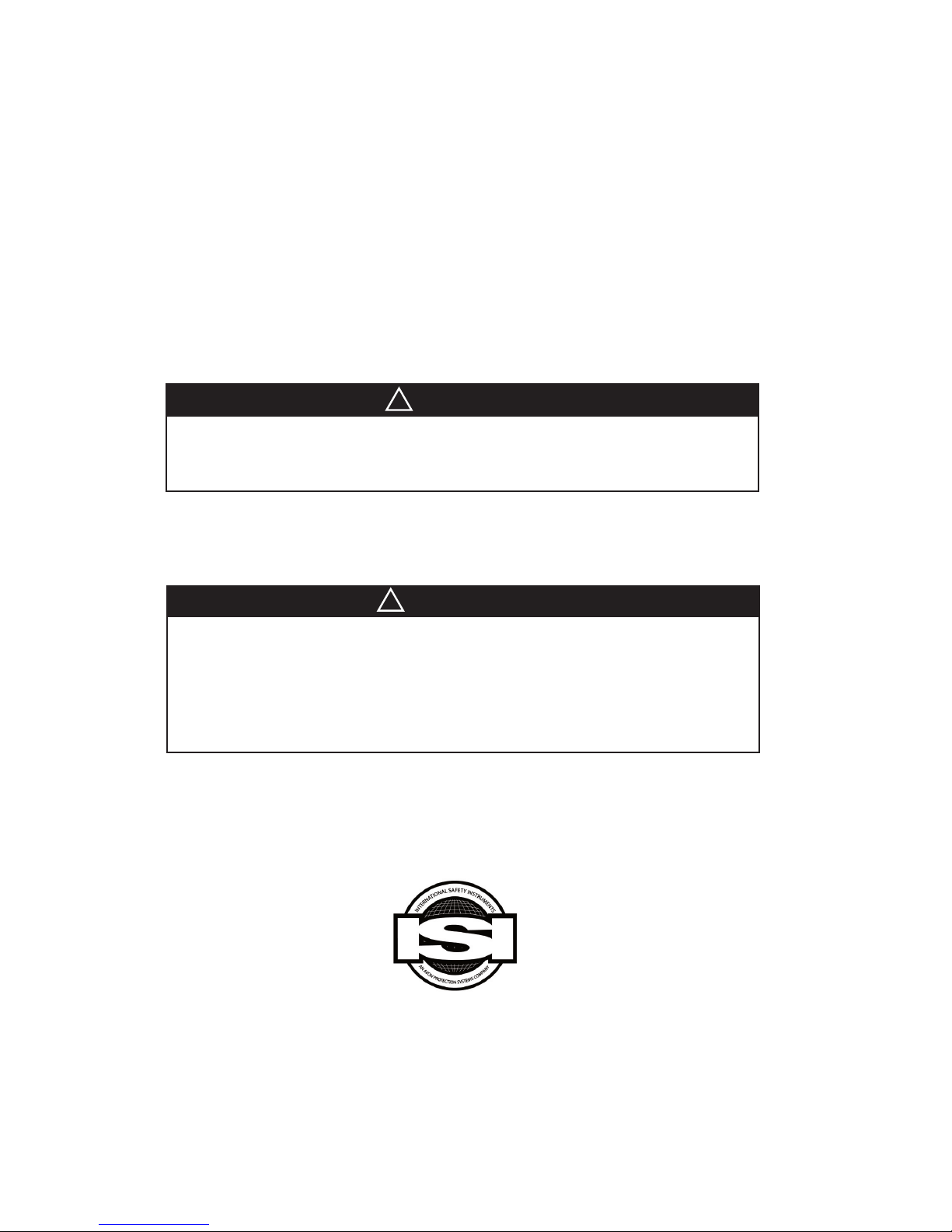
ISI 2500 & ISI3500
Thermal Imaging Systems
Owner’s Operation Manual
WARNING
!
Disassembly of the components beyond the procedures described herein
shall not be performed. Additional disassembly may cause component
damage and shall be performed only by authorized personnel or ISI.
!
ATTENTION
By order of the United States Department of Commerce Bureau of Export
Control, this Thermal Imaging Camera may not be shipped or hand carried
outside the borders of the owner’s home country without rst obtaining the
proper export license from their respective government department or the
United States Department of Commerce.
Violation of this warning may result in ne or imprisonment according to the
United States Export Administration Regulations, 15 CFR, Parts 730-774.
International Safety Instruments, Inc.
922 Hurricane Shoals Road Lawrenceville, GA 30043
678-495-3700 888-474-7233 (toll free) FAX 678-495-3875
www.avon-isi.com E-Mail: customer_service@avon-rubber.com
Part Number 084097 Issue F March 2010
Artwork Number A49180 Issue F March 2010
Copyright 2010 International Safety Instruments, Inc.2
An Avon Protection Systems Company

Preface
Warnings and Exclusions ........................................................................................4
1.0 Specications .................................................................................................................5
2.0 System Components ......................................................................................................5
3.0 General Operation ..........................................................................................................5
3.1 Battery Installation .............................................................................................5
3.2 On/Delay Off Button Operation .........................................................................6
3.3 Electronic Integration Mode ..............................................................................6
3.4 Kevlar Sidestrap ................................................................................................6
3.5 Kevlar Neckstrap ...............................................................................................6
3.6 Battery Life Indicator .........................................................................................6
3.7 Sensor Temperature Warning .....................................................................7
3.8 Battery Charging ...............................................................................................7
3.9 Direct Digital Readout - ISI 2500 .......................................................................8
3.10 Temperature Readout options - ISI 3500 ........................................................8
4.0 Options & Accessories ..................................................................................................9
4.1 Detachable Handle ............................................................................................9
4.2 Remote LCD & Extension Pole .........................................................................9
4.3 ISI Dual Channel 1.2 .......................................................................................10
5.0 Inspection and Maintenance ........................................................................................11
5.1 General Inspection After Each Use ................................................................11
5.2 Periodic Inspection .........................................................................................11
5.3 Battery Maintenance ......................................................................................11
5.4 Cleaning .........................................................................................................11
TABLE OF CONTENTS
!
!
6.0 Warranty .......................................................................................................................11
Copyright 2010 International Safety Instruments, Inc. 3

PREFACE
!
IMPORTANT POINTS
Please read all carefully
The ISI 2500 and ISI 3500 Thermal Imaging System is
not life support equipment and should not be used
as such. Failure to properly maintain and operate this
product could result in its’ failure, leading to possible
injury and/or death.
INTENT
This manual is intended to acquaint owners’ and users’
with the operation of the ISI 2500 and ISI 3500 Thermal
Imaging Systems and to provide important safety
information and limitations. All information, illustrations
and specications in this manual are based on the latest
product information available at the time of printing. The
right is reserved to make changes at any time without
notice.
!
IMPORTANT
All personnel using this product shall be
thoroughly familiar with the operation,
inspection and safety precautions outlined in
this manual.
Equipment should be thoroughly checked
and cleaned after exposure to intense heat or
harsh chemicals.
The ISI 2500 and 3500 is designed to be simple to
use and easy to maintain and will operate for many
years if properly handled, maintained and cleaned. The
instructions for care and use given in this manual must
be read, understood and carefully followed before the
equipment is used.
The procedures in this manual DO NOT render ISI liable
for any losses or injury arising from actions based on use
of same.
Spare parts and accessories are available through
your local ISI authorized distributor. Service beyond the
scope of this manual is not recommended. If a problem
arises, the equipment should be removed from service,
tagged for repair and forwarded to the ISI factory or an
ISI Camera Certied Service Center for evaluation and/
or repair.
DESCRIPTION
The ISI 2500 and ISI 3500 Thermal Imaging System is
designed to provide the trained user with the ability to
see in dark and smoke lled environments. Engineered
to withstand the rigors of reghting, the ISI 2500 and
3500 can be used for search and rescue, size-up, seat
of re location, HazMat, and overhaul operations. Once
integrated into the Standard Operating Procedures, the
ISI 2500 and 3500 will become one of the most important
reghting tools used to save lives and property.
OPERATOR INFORMATION, WARNINGS, LIMITATIONS
& TRAINING REQUIREMENTS
All operators must read, understand and be thoroughly
familiar with the operation and use of the equipment and
the contents of this operators manual prior to rst use.
!
WARNING: NEVER point the thermal imaging
camera directly at the sun.
!
WARNING: Improper use or abuse of this
equipment in a hazardous environment or
atmosphere could result in serious injury or
even death.
As with all re service equipment, standard operating
procedures must be written, implemented and
followed for the thermal imaging systems. Priority
should be given to proper egress should the
equipment malfunction or fail while inside the re
scene.
All operators and potential operators should receive
training in a controlled re scene simulation (i.e. training
tower or live burn) before actual use in a re environment.
Training shall include egress procedures should the
camera system fail.
Thermal Imaging Cameras and their accessories are not
life support equipment and shall not be used as such.
The service life or battery duration of this camera can
be reduced by heavy usage or extreme environmental
conditions. Every re scene and environment is unique
and therefore battery duration can not be predetermined
to an exact time limit. The operator is required to
IMMEDIATELY egress from the hazardous environment
when the yellow LED goes out leaving the red LED as
the only LED lit. Users’ should only enter a hazardous
environment with a fully charged battery. The re
environment affects the duration of the battery and
therefore exact duration time will vary from incident to
incident. Exposure to extreme high heat environments
for an extended period of time and repeated exposures
to high heat environments may result in the degradation
of the thermal image and possible damage to the camera
sensor. Allow for adequate cool down when exposed to
extreme high heat before reusing the camera. The user
shall adhere to the “Sensor Temperature Warning” section
(3.7) of this manual.
The thermal imaging camera is not capable of seeing
through glass, water or reective objects. Although IP67
waterproof, the camera cannot be used underwater. The
ISI 2500 and ISI 3500 is not rated as “intrinsically
safe.” Use extreme caution and avoid explosive
atmospheres when operating this camera. Radio
transmissions and other electromagnetic radiation may
cause interference with the ISI 2500 and 3500.
Copyright 2010 International Safety Instruments, Inc.4

1.0 SPECIFICATIONS
ISI 2500 THERMAL IMAGER
CONFIGURATION: Hand held
CASE CONSTRUCTION: Ultem
DIMENSIONS: Height 5.25 inches with visor
Width 6.25 inches
Length 8 inches
SENSOR: Amorphous Silicon Microbolometer
ARRAY SIZE: 160 x 120
WEIGHT: 3.8 lbs with battery
POWER SOURCE: 7.2 V, 4.5 Ah Rechargeable NiMH
Battery
OPERATING TIME: minimum 4 hours
FIELD OF VIEW: 50º x 35º
THERMAL SENSITIVITY: ‹ 100mK
VIDEO OUTPUT: EIA, 525 lines, 60Hz.
2.0 SYSTEM COMPONENTS
The ISI 2500 and ISI 3500 comes standard with:
(1) Thermal Imaging Camera
(2) Rechargeable NiMH Batteries
(1) External Battery Charger Kit
(1) Internal Battery Charger Kit
ISI 3500 THERMAL IMAGER
CONFIGURATION: Hand held
CASE CONSTRUCTION: Ultem
DIMENSIONS: Height 5.25 inches with visor
Width 6.25 inches
Length 8 inches
SENSOR: Amorphous Silicon Microbolometer
ARRAY SIZE: 160 x 120
WEIGHT: 3.8 lbs with battery
POWER SOURCE: 7.2 V, 4.5 Ah Rechargeable NiMH
Battery
OPERATING TIME: minimum 4 hours
FIELD OF VIEW: 50º x 35º
THERMAL SENSITIVITY: ‹ 50mK
VIDEO OUTPUT: EIA, 525 lines, 60Hz.
(1) Operation Manual
(1) Warranty Card
(1) Of the following:
Kevlar® Neckstrap
Kevlar® Short Lanyard
Retractable Lanyard
3.0 GENERAL OPERATION
3.1 Battery Installation & Removal
3.1.1 To install the battery, hold the camera rmly
in a comfortable position and line up the rails of the
battery with the tracks on the bottom of the camera
and slide it into place. Check for proper seating of the
battery by ensuring the forks of the release button on
the battery are not visible. If forks are visible, push
battery in, and forks up, until forks disappear.
!
CAUTION: Visible battery forks will increase
likelihood of battery detachment should camera be
dropped or slammed.
3.1.2 To remove the battery, hold the camera rmly
in a comfortable position and while pushing the
release button away from the camera slide the battery
completely off. Be sure the forks of the release button
are entirely disengaged before sliding.
!
CAUTION: If forks are not entirely disengaged,
forks can become damaged rendering the battery
non-usable.
!
WARNING: When in a hazardous environment,
the camera MUST BE TURNED OFF PRIOR TO
CHANGING BATTERIES. The camera is NOT
intrinsically safe.
Replacement batteries must be purchased
from the manufacturer’s distributor or the
manufacturer. Use of unapproved batteries or
chargers may result in system malfunction or
failure, which could lead to injury or death.
battery deector
!
WARNING: Do not use camera without the
battery deector in place.
NOTE: Leaving battery attached to camera without
internal charger connected will drain battery. Do not
leave internal charger connected to camera without
charger being plugged into a power source.
NOTE: When using EchoSeeker, refer to EchoSeries
manual.
Copyright 2010 International Safety Instruments, Inc. 5

3.2 On/Delay Off Button
on/off button
3.2.1 To turn the camera on, push the on/off button for
about one second then release. The camera will take
less than 3 seconds to provide a thermal image.
3.2.2 To turn the camera off, push and hold the on/off
button for 3 to 5 seconds until the image disappears.
3.3 Electronic Integration Mode
3.3.1 The thermal imaging sensor and electronics are
designed with an automatic gain control to optimize
the image quality in high temperature environments.
When the camera switches to EI Mode and the letters
“EI” appear on the screen.
®
3.4 Kevlar
Sidestraps
3.4.1 The straps are made of kevlar and use velcro
for adherence.
3.4.2 To adjust, simply separate the 2 velcro pieces
and either pull the strap back through the dowel pin
towards the viewing screen to loosen or pull it forward
through the dowel pin towards the optical lens to
tighten. The side straps are eld replaceable.
3.4.3 To remove the side straps, release the Velcro by
pulling the inner piece of webbing from the side strap.
3.4.4 Withdraw the webbing from the pin at the rear of
the camera.
3.4.5 Insert a nger, or two, along the side of the
camera to release the front bumper from the two
bumps that hold the pin. Be cautious not to tear the
bumper.
Copyright 2010 International Safety Instruments, Inc.6
3.4.6 Remove the front bumper from the camera, but
still have the two side straps woven through the slots
of the bumper. Note this conguration and orientation
of the webbing for future installation.
3.4.7 Remove the bumper completely and then
withdraw the side straps from the pin at the front of
the camera.
3.4.8 Installation is the reverse of this procedure.
3.5 Kevlar® Neckstrap
3.5.1 Attach the neckstrap by compressing the large
carabineer until the opening is sufcient enough to
be placed totally around the sidestrap. Release the
carabineer to secure. Repeat this procedure for the
other sidestrap. The neckstrap can be worn several
different ways and is up to the user’s discretion.
3.6 Battery Life Indicator
3.6.1 The battery life indicator is a series of LED lights
located on the right side of the camera next to the
screen.
!
CAUTION: It is
recommended to have a
full battery indicated before
entering a re scene.
green
3.6.2 The LED’s consist of
two green LED, one yellow
LED, and one red LED.
green
The top green LED will be
lit for 30 to 45 minutes.
The second green LED
yellow
and the yellow LED will be
lit for approximately 1.5
hours (or more depending
on the age of the battery
red
pack). The red LED will be
lit for approximately fteen
minutes. When the battery

level decreases to where the yellow LED turns off and
only the red LED is lit, the operator must immediately
leave the hazardous environment.
!
CAUTION: Due to the unknown hazardous
conditions of the environment and the environments
effect on the battery, the 15 minutes are NOT
guaranteed.
3.7 Sensor Temperature Warning
!
3.7.1 Should the internal temperature of the camera
begin to reach its operating limit, all four LED begin to
blink. Operator must immediately leave the hazardous
environment when warning appears.
!
CAUTION: Due to the numerous environmental
variations between re scenes, there is no way to
predict the amount of time before sensor shutdown
after the warning appears on screen.
3.8 Battery Charging
3.8.1 Internal Battery Charger
3.8.1.1 To set up the internal charger, connect
the power cord to the charger block. Plug the
charger block into the charger base. Plug the
power cord into a wall 110 outlet. The red LED
will come on if properly connected.
at section
3.8.1.2 To connect the internal battery charger,
turn the camera over and place the optical lens
facing you. Take the battery connector cord
and line up the red dot on the cord connector
with the at section of the second ring of the
camera connector (see picture). Push the cord
connector into the camera connector until
secure. Check the charger LED to determine
proper connection and battery/charger status.
NOTE: Do not fold or drastically bend
connector cable.
3.8.1.3 To remove or unplug internal charger,
grab the connector by the ribs and pull straight
out.
!
WARNING: Pulling cord or non-ribbed
section of connector will damage the
charger and rend it useless.
!
CAUTION: Do not leave the charger
plugged into the camera without power. Do not
use power supplies other than those provided.
3.8.2 External Battery Charger
3.8.2.1 To set up the external charger, connect
the power cord into the charger block. Plug
the charger block into the charger base. Plug
the power cord into a wall 110 outlet. The
red, yellow and green LEDs will illuminate in
sequence, twice.
3.8.2.2 To install battery, line up the rails of the
battery with the tracks on the charger base and
slide it into place. Check for proper seating of
the battery by ensuring the forks of the release
button on the battery are not visible. If forks are
visible, push battery in until forks disappear.
NOTE: Both the internal and external chargers
come with 12 V DC charging plugs. Simply
replace the power cord and charger block with
the 12 V DC charging plug and follow the steps
in 3.8.1.1 and 3.8.2.1.
3.8.3 External Battery Charger Status
3.8.3.1 When the battery is slipped on, the red,
LED will light-up.
3.8.3.2 Depending on the starting voltage in
the battery, the battery charge time will be two
to three hours. The rst green LED will begin to
blink when the battery is fully charged.
3.8.3.3 The fully charged battery may be
left on the charger indenitely. The charger
automatically switches to maintenance mode
when the battery reaches full charge status.
3.8.4 Internal & External Charge Status
3.8.4.1 The following diagrams directly
correspond to the labels on the charger
bases. Please familiarize all operators with the
following indicators:
External Charger Label
Copyright 2010 International Safety Instruments, Inc. 7

Internal Charger Label
3.10 TEMPERATURE READOUT OPTIONS- ISI 3500
3.10.1 The Direct Digital Readout system is a noncontact temperature measurement feature that allows
reghters to estimate the surface temperature of
objects from a remote location.
3.10.1.1 Direct Digital Readout is a standard
feature of the ISI 3500 (may be ordered without
this option).
digital
temperature
readout
crosshairs
3.8.4.2 The battery is fully charged and in trickle
mode when the red (R), yellow (Y), and rst
green (G1) LED are lit with the second green
(G2) LED blinking. Should the “charger fault
condition” appear (R LED blinking), the charger
is not working properly and needs repair.
Should the “battery fault condition” appear
(the R, Y, and G1 LED blinking), the battery is
no longer usable and should be disposed of
properly.
3.8.4.3 A battery will take approximately
two hours or less to charge under normal
conditions.
3.8.4.4 Each LED when continually lit signies
a portion of charge status as indicated on the
labels.
3.9 DIRECT DIGITAL READOUT - ISI 2500
3.9.1 The Direct Digital Readout system is a noncontact temperature measurement feature that allows
reghters to estimate the surface temperature of
objects from a remote location.
3.9.2 Direct Digital Readout is a standard feature of
the ISI 2500.
3.9.3 The temperature is digitally displayed on
the screen in the bottom right corner. (See Image
3.10.1.1)
3.9.4 To measure the approximate temperature of an
object, place the crosshairs on the center of the object
and read the digital readout. Direct Digital Readout
takes a one foot diameter to every 49 feet of distance.
The further away the object, the more ambient air
and particles in the air inuence the temperature
reading.
!
CAUTION: Direct Digital Readout is an
informational tool ONLY. The accuracy of the
temperature readout is subject to many variations
- emissivity, distance, ambient air temperature, etc. and should not be used as an absolute.
bar
temperature
readout
3.10.1.2 The temperature is digitally displayed
on the screen in the bottom right corner or above
the temperature scale (if the temperature scale
readout option is ordered).
3.10.1.3 To measure the approximate
temperature of an object, place the crosshairs
on the center of the object and read the digital
readout. Direct Digital Readout takes a one
foot diameter to every 49 feet of distance. The
further away the object, the more ambient air
and particles in the air inuence the temperature
reading.
!
CAUTION: Direct Digital Readout is an
informational tool ONLY. The accuracy of the
temperature readout is subject to many variations
- emissivity, distance, ambient air temperature, etc. and should not be used as an absolute.
3.10.2 The Temperature Scale Readout system is a
non-contact temperature measurement feature that
allows reghters to estimate the surface temperature
of objects from a remote location.
3.10.2.1 Temperature Scale Readout is an
optional feature of the ISI 3500.
3.10.2.2 The temperature scale is displayed
on the right side of the screen and ranges from
0ºF to 1200ºF (0ºC to 600ºC) with graduations
marked every 300ºF (150ºC).
3.10.2.3 To measure the approximate
temperature of an object, place the crosshairs on
the center of the object and read the approximate
temperature on the scale. The Temperature Scale
Readout takes a one foot diameter to every 49
feet of distance. The further away the object, the
more ambient air and particles in the air inuence
the temperature reading.
Copyright 2010 International Safety Instruments, Inc.8

!
CAUTION: The Temperature Scale Readout is
an informational tool ONLY. The accuracy of the
temperature readout is subject to many variations
(emissivity, distance, ambient air temperature, etc.)
and should not be used as an absolute.
3.10.3 The Temperature Colorization system is a
non-contact temperature informational feature that
allows reghters to estimate the surface, air and gas
temperatures in a very high heat environment.
3.10.3.1 The Temperature Colorization system
is a standard feature of the ISI 3500 (may be
ordered without this option).
3.10.3.2 This feature is automatically on and
does not require any directional input or accurate
aiming by the reghter to operate.
3.10.3.3 All surfaces and gases having a
temperatures greater than 500ºF (260ºC) will be
yellow, 700ºF (371ºC) will be orange, and 900ºF
(482ºC) will be red. As the temperature rises
4.0 OPTIONS AND ACCESSORIES
between these designated temperature levels,
there will be a gradual change in color from
yellow to orange and then orange to red.
!
CAUTION: The Temperature Scale Readout
is an informational tool ONLY. The accuracy of the
temperature readout is subject to many variations
(emissivity, distance, ambient air temperature, etc)
and should not be used as an absolute.
4.1 Detachable Handle
4.1.1 The detachable handle comes assembled
and ready to install. The assembly consists of the
following components:
Part Description Part #
Handle 045144
Head 045145
Wrist Strap Assembly 138035
Attachment Plate 045128
Long Handle Screw (1) 030.147.00
Attachment Plate Screws(2) 030095
4.1.2 Attaching the handle:
4.1.2.1 First turn the camera upside down and
take off the battery deector by removing the 2
screws holding it in place. Place deector in a
safe storage area. Do not discard.
4.1.2.2 Line up the handle assembly holes with
the deector screw holes of the camera.
4.1.2.3 Using the battery deector screws,
securely fasten the handle assembly to the
camera.
WARNING: Never use the camera
!
without either the battery deector or the
detachable handle in place,unless using the
ISI EchoSeeker. Failure to do so may cause
battery to become dislodged during use,
should the camera be dropped, hit, slammed,
or banged, thus causing the camera to stop
operating.
4.1.3 The handle may be attached in the opposite
angle of its original conguration. In order to change
the angle prior to attachment to camera, remove
the attachment plate and reverse its’ direction. Then
follow the attachment instructions (4.1.2) above.
4.1.4 Attaching the handle to the transmitter:
4.1.4.1 Remove the handle attachment plate from
the handle by removing the two screws.
4.1.4.2 Place the attachment slide on the handle
head and secure with the two screws.
4.1.4.3 Turn camera over. Pull down on handle
latch and slide handle into place until securely
locked. NOTE: Handle slides-in in either direction.
4.2 Remote LCD & Extension Pole
4.2.1 The Remote LCD & Extension Pole comes
complete with 1 remote LCD, 1 2-section extension
pole, 1 extension pole deector, and 1 coiled cable.
4.2.2 Attaching the pole
4.2.2.1 First turn the camera upside down and
take off the battery deector by removing the 2
screws holding it in place. Place deector in a
safe storage area. Do not discard.
4.2.2.2 Place the extension pole deector on the
camera and secure with the 2 screws.
4.2.2.3 Screw the extension pole into the
extension pole deector until secure. NOTE: Be
sure the locking cap is in place prior to attaching
the pole.
4.2.3 Attaching the cable
4.2.3.1 Plug the small connector of the cable
into the Remote LCD and then take the large
connector and line up the red dot with the
at section of the second ring of the camera
Copyright 2010 International Safety Instruments, Inc. 9

connector. Push the cable connector into the
camera connector until secure.
4.2.4 Operation
4.2.4.1 Snap the remote LCD onto the pole if
desired.
4.2.4.2 To activate the Remote LCD, simply plug
it into a camera that is already turned on or plug it
into the camera and then turn the camera on. The
remote LCD utilizes the camera battery and will
cause the battery duration time to be cut it half.
4.2.4.3 To extend or shorten the pole, simply push
and hold down the extension release button found
at the end of the rst pole section and pull or push
the second pole section to desired length. Be
sure the extension release button locks in place.
4.3 ISI Dual Channel 1.2
4.3.1 The ISI Dual Channel is a 2-channel
transmitter that operates in the 2.4GHz frequency.
The transmitter is 1 watt and will diminish the battery
duration of the camera in half.
4.3.2 Attaching the transmitter
4.3.2.1 First turn the camera upside down and
take off the battery deector by removing the 2
screws holding it in place. Place deector in a
safe storage area. Do not discard.
4.3.2.2 Line up the transmitter screw holes with
the deector screw holes of the camera.
4.3.2.3 Using the battery deector screws,
securely fasten the transmitter to the camera.
4.3.2.4 Take the transmitter connector cord and
line up the red dot on the cord connector with
the at section of the second ring of the camera
connector. Push the cord connector into the
camera connector until secure.
!
WARNING: Never use the camera without
either the battery deector or the transmitter
in place. Failure to do so may cause battery
to become dislodged during use, should the
camera be dropped, hit, slammed, or banged,
thus causing the camera to stop operating.
4.3.3 Connecting Receiver to Monitor/TV
4.3.3.2 The receiver is automatically “on” as soon
as you plug it in.
4.3.3.3 Connect the receiver’s Video-out to the
Video-In of your Monitor/TV.
4.3.3.4 Set your Monitor/TV to receive the signal
from the receiver. The Monitor/TV must be set to
receiver signal from the Video-In plug. Refer to
the manual supplied with your TV/Monitor.
4.3.4 Channel selection
4.3.4.1 Locate the channel toggle switch on the
bottom of the transmitter and either push forward
or backward for desired channel. The switch will
reset in the middle after selection.
4.3.4.2 Select the corresponding channel on the
receiver by use of the toggle switch.
4.3.5 Transmitting
4.3.5.1 Turn on the camera and Monitor/TV.
4.3.5.2 To select or change channels on the
transmitter, simply switch the toggle switch.
4.3.5.3 Select the corresponding channel on the
receiver by use of the toggle switch.
power
video
out
4.3.3.1 Connect the power supply to the receiver.
Use only the power supply unit supplied with the
receiver.
Copyright 2010 International Safety Instruments, Inc.10

5.0 INSPECTION AND MAINTENANCE
5.1 General Inspection After Each Use
!
CAUTION: The thermal imaging camera should be
tested before each use.
5.1.1 Inspect the camera, batteries and optional
transmitter for structural, heat and/or chemical
damage. Cameras with signs of damage should be
taken out of service and returned to the factory for
repair. Call ISI customer service at 888-474-7233 for
a return authorization number.
5.1.2 Inspect side strap, wrist strap, neckstrap, short
lanyard and retractable lanyard along with neckstrap
clip for damage and/or fraying. If any strap is frayed
or damaged, replace before next use. Check that all
screws are tight.
NOTE: Screws for viewing lens will NOT tighten
completely. Check to be sure they are secure and not
sticking out from case.
5.1.3 Inspect visor and front bumper for cracks, rips or
wear. Special attention should be given to the areas
used for side strap connection.
5.1.4 Check that warning labels are intact and legible.
Pay special attention to the labels on the battery.
Should either label appear damaged, IMMEDIATELY
place the battery out of service. Return the battery for
repair or replacement.
5.1.5 Inspect latch mechanism.
5.1.6 Inspect charging port for visible damage.
5.2 Weekly Inspection
5.2.1 Inspect battery charger for proper operation
and LED indicators. Check charger contact points for
corrosion or damage.
5.2.2 Inspect all batteries for damage, leakage,
corrosion, and for damage to the contacts and labels.
5.3 Battery Maintenance
5.3.1 It is not recommended that a battery be left
in the camera when not in use unless the internal
charger is connected and operating. The battery will
drain at a higher rate if left on the camera then if
stored off the camera.
5.3.2 Battery cannot be disposed of as municipal
waste and must be collected and disposed of
separately where appropriate public or private waste
collection systems are dened by national and local
regulations.
5.4 Cleaning
5.4.1 Camera Housing
To clean the camera housing use a medium
bristle brush or sponge and a mild non-detergent
dishwashing soap. Do not use bleach or any other
compound containing chlorine.
5.4.2 Optical Lens & Viewing Lens
To clean the optical lens use lens paper and
photography grade lens cleaner available at your local
camera store. Do not use paper towels or any other
abrasive material for they will scratch the lens.
IMPORTANT WARRANTY INFORMATION:
EACH PRODUCT IS SHIPPED WITH A WARRANTY CARD. TO RECEIVE TECHNICAL UPDATES ON
THIS PRODUCT YOU MUST REGISTER ONLINE OR COMPLETE AND RETURN THE LOWER PORTION
Register your equipment online at www.avon-isi.com
6.0 WARRANTY
OF THE WARRANTY CARD.
Copyright 2010 International Safety Instruments, Inc. 11
 Loading...