

International Safety Instruments ISI 2500, ISI3500 Owner's Instruction Manual
International Safety Instruments, Inc.
I
N
T
E
R
N
A
T
I
O
N
A
L
S
A
F
E
T
Y
I
N
S
T
R
U
M
E
N
T
S
A
N
A
V
O
N
P
R
O
T
E
C
T
I
O
N
S
Y
S
T
E
M
S
C
O
M
P
A
N
Y
An Avon Protection Systems Company
Advanced
Thermal Imaging
Systems
Owner’s Instruction Manual
Copyright 2010 International Safety Instruments, Inc. 1
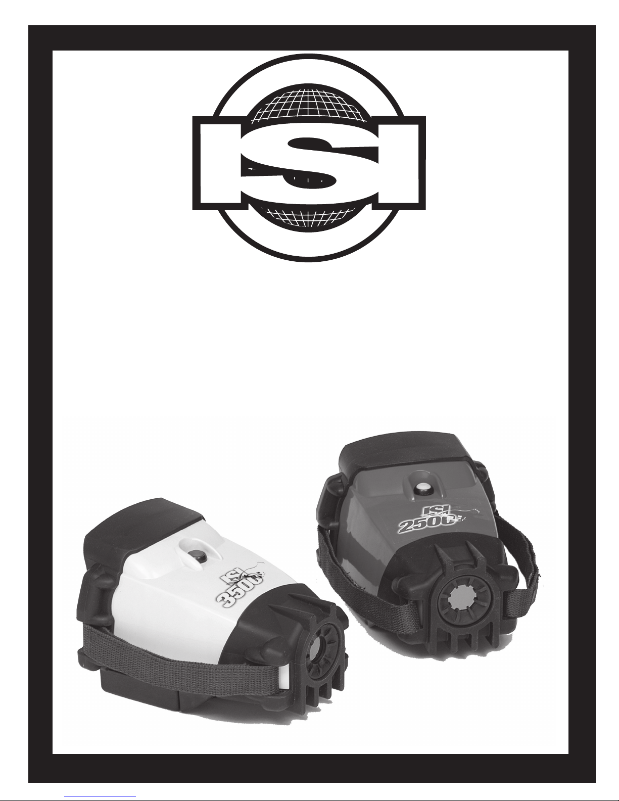
ISI 2500 & ISI3500
Thermal Imaging Systems
Owner’s Operation Manual
WARNING
!
Disassembly of the components beyond the procedures described herein
shall not be performed. Additional disassembly may cause component
damage and shall be performed only by authorized personnel or ISI.
!
ATTENTION
By order of the United States Department of Commerce Bureau of Export
Control, this Thermal Imaging Camera may not be shipped or hand carried
outside the borders of the owner’s home country without rst obtaining the
proper export license from their respective government department or the
United States Department of Commerce.
Violation of this warning may result in ne or imprisonment according to the
United States Export Administration Regulations, 15 CFR, Parts 730-774.
International Safety Instruments, Inc.
922 Hurricane Shoals Road Lawrenceville, GA 30043
678-495-3700 888-474-7233 (toll free) FAX 678-495-3875
www.avon-isi.com E-Mail: customer_service@avon-rubber.com
Part Number 084097 Issue F March 2010
Artwork Number A49180 Issue F March 2010
Copyright 2010 International Safety Instruments, Inc.2
An Avon Protection Systems Company

Preface
Warnings and Exclusions ........................................................................................4
1.0 Specications .................................................................................................................5
2.0 System Components ......................................................................................................5
3.0 General Operation ..........................................................................................................5
3.1 Battery Installation .............................................................................................5
3.2 On/Delay Off Button Operation .........................................................................6
3.3 Electronic Integration Mode ..............................................................................6
3.4 Kevlar Sidestrap ................................................................................................6
3.5 Kevlar Neckstrap ...............................................................................................6
3.6 Battery Life Indicator .........................................................................................6
3.7 Sensor Temperature Warning .....................................................................7
3.8 Battery Charging ...............................................................................................7
3.9 Direct Digital Readout - ISI 2500 .......................................................................8
3.10 Temperature Readout options - ISI 3500 ........................................................8
4.0 Options & Accessories ..................................................................................................9
4.1 Detachable Handle ............................................................................................9
4.2 Remote LCD & Extension Pole .........................................................................9
4.3 ISI Dual Channel 1.2 .......................................................................................10
5.0 Inspection and Maintenance ........................................................................................11
5.1 General Inspection After Each Use ................................................................11
5.2 Periodic Inspection .........................................................................................11
5.3 Battery Maintenance ......................................................................................11
5.4 Cleaning .........................................................................................................11
TABLE OF CONTENTS
!
!
6.0 Warranty .......................................................................................................................11
Copyright 2010 International Safety Instruments, Inc. 3

PREFACE
!
IMPORTANT POINTS
Please read all carefully
The ISI 2500 and ISI 3500 Thermal Imaging System is
not life support equipment and should not be used
as such. Failure to properly maintain and operate this
product could result in its’ failure, leading to possible
injury and/or death.
INTENT
This manual is intended to acquaint owners’ and users’
with the operation of the ISI 2500 and ISI 3500 Thermal
Imaging Systems and to provide important safety
information and limitations. All information, illustrations
and specications in this manual are based on the latest
product information available at the time of printing. The
right is reserved to make changes at any time without
notice.
!
IMPORTANT
All personnel using this product shall be
thoroughly familiar with the operation,
inspection and safety precautions outlined in
this manual.
Equipment should be thoroughly checked
and cleaned after exposure to intense heat or
harsh chemicals.
The ISI 2500 and 3500 is designed to be simple to
use and easy to maintain and will operate for many
years if properly handled, maintained and cleaned. The
instructions for care and use given in this manual must
be read, understood and carefully followed before the
equipment is used.
The procedures in this manual DO NOT render ISI liable
for any losses or injury arising from actions based on use
of same.
Spare parts and accessories are available through
your local ISI authorized distributor. Service beyond the
scope of this manual is not recommended. If a problem
arises, the equipment should be removed from service,
tagged for repair and forwarded to the ISI factory or an
ISI Camera Certied Service Center for evaluation and/
or repair.
DESCRIPTION
The ISI 2500 and ISI 3500 Thermal Imaging System is
designed to provide the trained user with the ability to
see in dark and smoke lled environments. Engineered
to withstand the rigors of reghting, the ISI 2500 and
3500 can be used for search and rescue, size-up, seat
of re location, HazMat, and overhaul operations. Once
integrated into the Standard Operating Procedures, the
ISI 2500 and 3500 will become one of the most important
reghting tools used to save lives and property.
OPERATOR INFORMATION, WARNINGS, LIMITATIONS
& TRAINING REQUIREMENTS
All operators must read, understand and be thoroughly
familiar with the operation and use of the equipment and
the contents of this operators manual prior to rst use.
!
WARNING: NEVER point the thermal imaging
camera directly at the sun.
!
WARNING: Improper use or abuse of this
equipment in a hazardous environment or
atmosphere could result in serious injury or
even death.
As with all re service equipment, standard operating
procedures must be written, implemented and
followed for the thermal imaging systems. Priority
should be given to proper egress should the
equipment malfunction or fail while inside the re
scene.
All operators and potential operators should receive
training in a controlled re scene simulation (i.e. training
tower or live burn) before actual use in a re environment.
Training shall include egress procedures should the
camera system fail.
Thermal Imaging Cameras and their accessories are not
life support equipment and shall not be used as such.
The service life or battery duration of this camera can
be reduced by heavy usage or extreme environmental
conditions. Every re scene and environment is unique
and therefore battery duration can not be predetermined
to an exact time limit. The operator is required to
IMMEDIATELY egress from the hazardous environment
when the yellow LED goes out leaving the red LED as
the only LED lit. Users’ should only enter a hazardous
environment with a fully charged battery. The re
environment affects the duration of the battery and
therefore exact duration time will vary from incident to
incident. Exposure to extreme high heat environments
for an extended period of time and repeated exposures
to high heat environments may result in the degradation
of the thermal image and possible damage to the camera
sensor. Allow for adequate cool down when exposed to
extreme high heat before reusing the camera. The user
shall adhere to the “Sensor Temperature Warning” section
(3.7) of this manual.
The thermal imaging camera is not capable of seeing
through glass, water or reective objects. Although IP67
waterproof, the camera cannot be used underwater. The
ISI 2500 and ISI 3500 is not rated as “intrinsically
safe.” Use extreme caution and avoid explosive
atmospheres when operating this camera. Radio
transmissions and other electromagnetic radiation may
cause interference with the ISI 2500 and 3500.
Copyright 2010 International Safety Instruments, Inc.4
 Loading...