

查询IRK320供应商
Bulletin I27090 rev. C 05/02
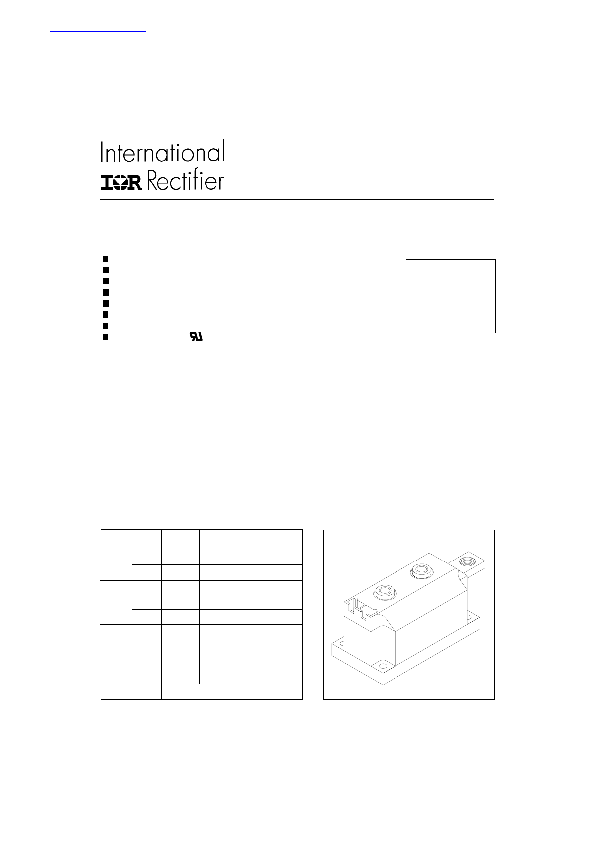
IRK. SERIES
STANDARD RECOVERY DIODES
Features
High voltage
Electrically isolated base plate
3000 V
Industrial standard package
Simplified mechanical designs, rapid assembly
High surge capability
Large creepage distances
UL E78996 approved
isolating voltage
RMS
Description
This new IRK series of MAGN-A-paks uses high voltage
power diodes in two basic configurations. The semiconductors are electrically isolated from the metal base ,
allowing common heatsinks and compact assemblies to
be built. They can be interconnected to form single
phase or three phase bridges and the single diode
module can be used in conjunction with the thyristor
modules as a freewheel diode. These modules are
intended for general purpose applications such as
battery chargers, welders and plating equipment and
where high voltage and high current are required (motor
drives, etc.).
MAGN-A-pak
Power Modules
250A
270A
320A
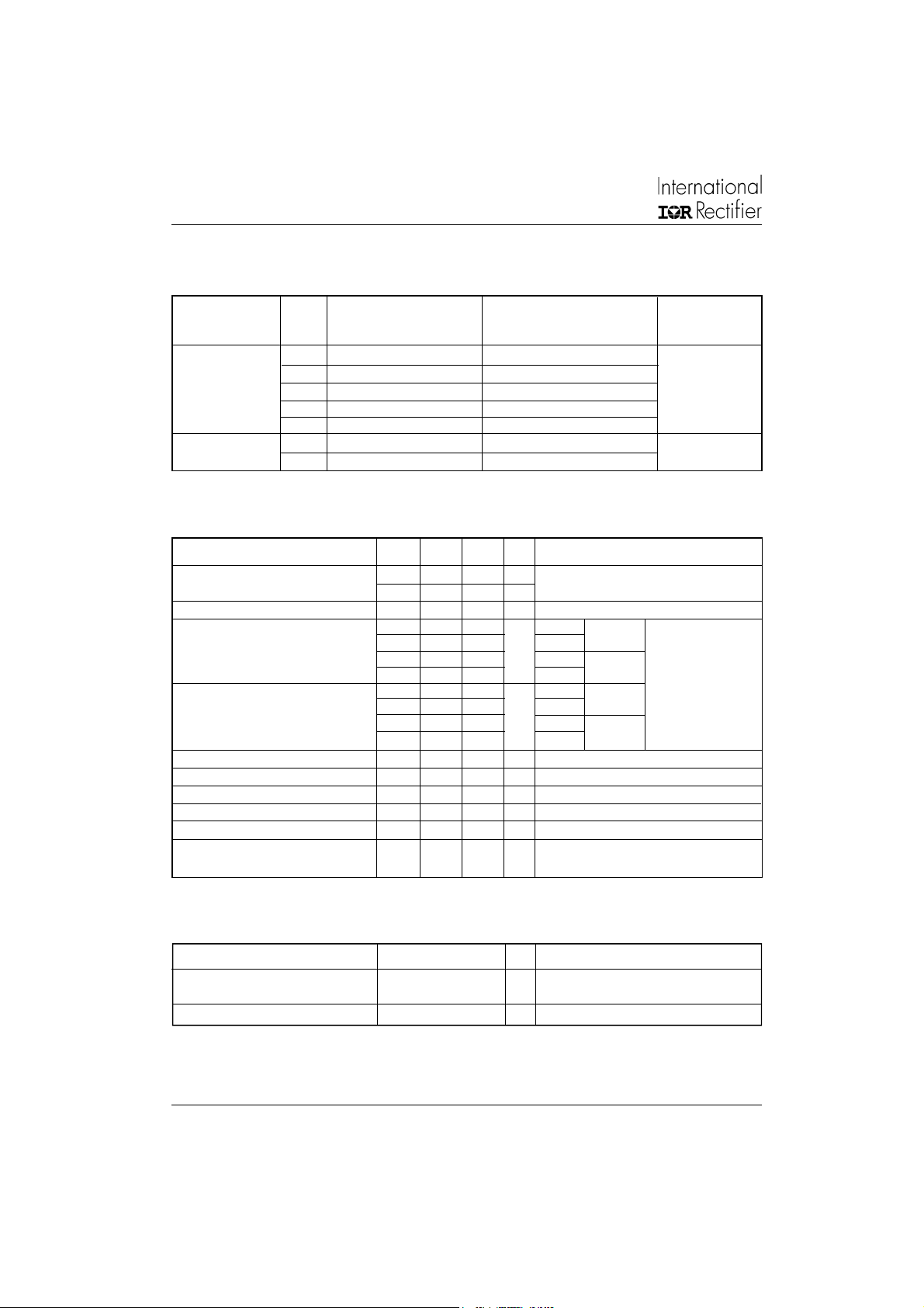
Major Ratings and Characteristics
Parameters IRK.250.. IRK.270.. IRK.320.. Units
I
F(AV)
@ T
I
F(RMS)
I
@ 50Hz 7015 8920 10110 A
FSM
@ 60Hz 7345 9430 10580 A
I2t @ 50Hz 246 398 511 KA2s
@ 60Hz 225 363 466 KA2s
2
I
√t 2460 3980 5110 KA2√s
V
RRM
T
J
www.irf.com
250 270 320 A
100 100 100 °C
C
393 424 502 A
Up to 2000 Up to 3000 Up to 2000 V
-40 to 150
o
C
1
IRK.250, .270, .320 Series
Bulletin I27090 rev. C 05/02
ELECTRICAL SPECIFICATIONS
Voltage Ratings
Type number Voltage V
Code peak reverse voltage peak reverse voltage @ 150°C
IRK.250- 04 400 500 50
IRK.270- 08 800 900
IRK.320- 12 1200 1300
16 1600 1700
20 2000 2100
IRK.320- 24 2400 2500 50
30 3000 3100
Forward Conduction
Parameters IRK.250 IRK.270 IRK.320 Units Conditions
I
Maximum average forward current 250 270 320 A 180o conduction, half sine wave
F(AV)
@ Case temperature 100 100 100
Maximum RMS forward current 393 424 502 A as AC switch
I
F(RMS)
I
Maximum peak, one-cycle forward, 7015 8920 10110 A t = 10ms No voltage
FSM
non-repetitive surge current 7345 9340 10580 t = 8.3ms reapplied
2
I
t Maximum I2t for fusing 246 398 511 KA2s t = 10ms No voltage Initial TJ = TJ max
2
√t Maximum I2√t for fusing 2460 3980 5110 KA2√s t = 0.1 to 10ms, no voltage reapplied
I
V
Low level val. of threshold voltage 0.79 0.74 0.69 V (16.7% x π x I
F(TO)1
High level val. of threshold voltage 0.92 0.87 0.86 V (I > π x I
V
F(TO)2
r
Low level forward slope resistance 0.63 0.94 0.59 mΩ (16.7% x π x I
t1
r
High level forward slope resistance 0.49 0.81 0.44 mΩ (I > π x I
t2
Maximum forward voltage drop 1.29 1.48 1.28 V I
V
FM
, Maximum repetitive V
RRM
, Maximum non-repetitive I
RSM
VVm A
o
C
5900 7500 8500 t = 10ms 100% V
6180 7850 8900 t = 8.3ms reapplied Sinusoidal half wave,
225 363 466 t = 8.3ms reapplied
174 281 361 t = 10ms 100% V
159 257 330 t = 8.3ms reapplied
F(AV)
F(AV)
= π x I
FM
Av. power = V
RRM
RRM
< I < π x I
F(AV)
), TJ = TJ max.
< I < π x I
F(AV)
), TJ = TJ max.
, TJ = TJ max., 180o conduction
F(AV)
x I
F(AV)
+ rf x (I
F(TO)
FAV)
F(AV)
), T
J
) TJ = T
F(RMS)
RRM
= T
Max
max.
J
max.
J
2
)
Blocking
Parameter IRK.250 /.270 /.320 Units Conditions
I
Max. peak reverse leakage 50 mA T
RRM
current
RMS isolation voltage 3000 V 50Hz, circuit to base, all terminals shorted, t =1sec
V
INS
= 150oC
J
2
www.irf.com
IRK.250, .270, .320 Series
Bulletin I27090 rev. C 05/02
Thermal and Mechanical Specifications
Parameter IRK.250 / .270 / .320 Units Conditions
T
Max. junction operating -40 to 150 °C
J
temperature range
T
Max. storage temperature range -40 to 150 °C
stg
Max. thermal resistance, 0.16 0.125 0.125 K/W Per junction, DC operation
R
thJC
junction to case
R
Max. thermal resistance, 0.035 K/W
thCS
case to heatsink
T Mounting torque ±10%
MAP to heatsink 4 to 6 Nm
busbar to MAP 8 to 10
wt Approximate weight 800 (30) g (oz)
∆R Conduction (per Junction)
(The following table shows the increment of thermal resistance R
Devices Units
Sinusoidal conduction @ TJ max. Rectangular conduction @ TJ max.
o
180o120
o
90
60
IRK.250- 0.009 0.010 0.014 0.020 0.032 0.007 0.011 0.015 0.021 0.033 K/W
IRK.270- 0.008 0.012 0.014 0.020 0.032 0.007 0.011 0.015 0.020 0.033
IRK.320- 0.008 0.010 0.013 0.020 0.032 0.007 0.011 0.015 0.020 0.033
when devices operate at different conduction angles than DC)
thJC
o
o
30
Mounting surface flat, smooth and greased
Per module
A mounting compound is recommended
and the torque should be rechecked after
a period of 3 hours to allow for the spread
of the compound
180
o
120
o
o
90
o
60
o
30
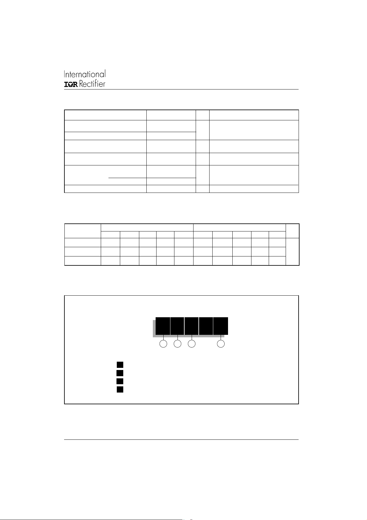
Ordering Information Table
Device Code
11 - Module type
2 - Circuit configuration
3 - Current rating: I
4 - Voltage code: Code x 100 = V
IRK D 32020 - 2424
1 2
F(AV)
3
x 10 rounded
RRM
4
(see Voltage Rating Table)
3www.irf.com
IRK.250, .270, .320 Series
Bulletin I27090 rev. C 05/02
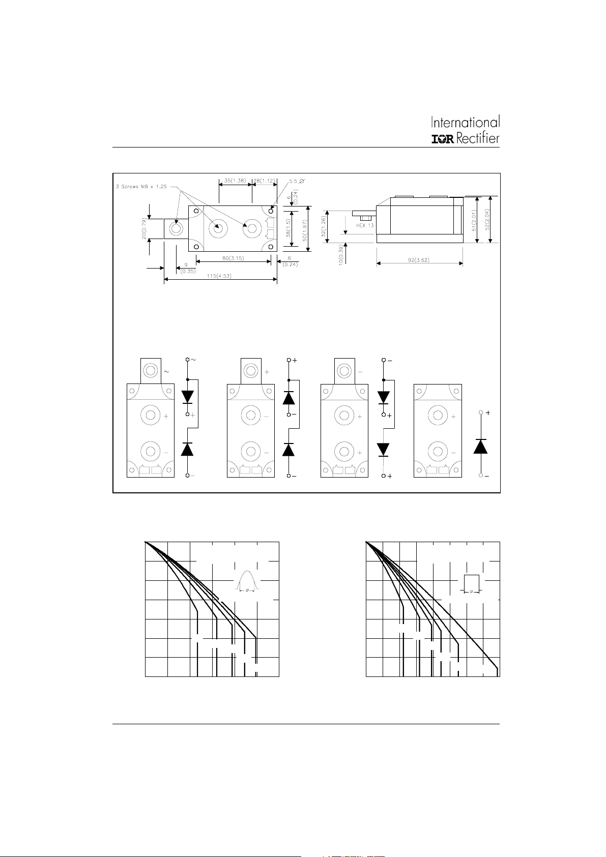
Outline Table
- All dimensions in millimeters (inches)
- Dimensions are nominal
- Full engineering drawings are available on request
- UL identification number for cathode wire: UL 1385
- UL identification number for package: UL 94V0
IRKD... IRKC... IRKJ... IRKE...
150
140
130
120
110
100
90
80
Maximum Allowable Case Temperature ( C)
0 50 100 150 200 250 300
Average Forward Current (A)
Fig. 1 - Current Ratings Characteristics Fig. 2 - Current Ratings Characteristics
IRK.250.. Series
R (D C) = 0.16 K/W
thJC
Conduction Angle
30
60
90
120
180
4
150
140
130
120
110
100
90
80
Maximum Allowable Case Temperature ( C)
0 50 100 150 200 250 300 350 400
Average Forward Current (A)
IRK.250.. Series
R (DC) = 0.16 K/W
thJC
30
60
90
120
Conduction Period
180
www.irf.com
DC

IRK.250, .270, .320 Series
Bulletin I27090 rev. C 05/02
300
250
200
180
120
90
60
30
RMS Limit
150
100
50
0
Maxim um Average Forward Power Loss (W)
0 50 100 150 200 250
Conduction Angle
IRK.250.. Series
T = 150 C
J
Average Forward Current (A)
Fig. 3 - Forward Power Loss Characteristics
600
500
400
300
200
100
Maxim um To tal Forward Pow er Loss (W)
0
0 50 100 150 200 250 300 350 400
Total RMS O utput Current (A)
450
400
350
300
250
200
150
100
50
0
Maximum Average Forward Power Loss (W)
R
t
h
S
0
A
.
0
=
8
0
K
0
/
.
0
W
.
180
(Sine)
DC
IRK.250.. Series
Per Junction
T = 150 C
J
1
2
K
/
W
0
.
2
K
/
W
0
.
2
5
K
/
W
0
.
4
K
/
W
0
.
6
K
/
W
2
K
0 255075100125150
Maximum Allowable Ambient Temperature ( C)
Fig. 5 - Forward Power Loss Characteristics
DC
180
120
90
60
30
RMS Limit
Conduction Period
IRK.250.. Series
T = 150 C
J
0 50 100 150 200 250 300 350 400
Average Forward Current (A)
Fig. 4 - Forward Power Loss Characteristics
/
W
D
e
l
t
a
R
Maximum Total Power Loss (W)
www.irf.com
1200
1000
800
180
(Sine )
180
(Re c t)
600
400
2 x IRK.250.. Series
200
0
0 100 200 300 400 500
Single Phase Bridge
Connected
T = 150 C
J
Total Outpu t Cu rrent (A)
Fig. 6 - Forward Power Loss Characteristics
0
.
0
0
.
5
0
8
K
K
0
.
1
K
/
0
.
1
6
K
0
.
2
5
K
0
.
3
5
K
/
/
W
W
W
/
W
/
W
/
W
R
0
.
t
0
h
3
S
A
K
/
W
=
0
.
0
1
K
/
W
D
e
l
t
a
R
0 25 50 75 100 125 150
Maximum Allowable Ambient Temperature ( C)
5

IRK.250, .270, .320 Series
Bulletin I27090 rev. C 05/02
1800
1600
1400
1200
1000
120
(Rect)
800
600
400
Maximum Total Power Loss (W)
200
0
0 100 200 300 400 500 600 700 800
3 x IRK.250.. Series
Three Phase Bridge
Connected
T = 150 C
J
Tota l Outp ut Current (A)
Fig. 7 - Forward Power Loss Characteristics
6500
At Any Rated Load Condition And With
6000
5500
5000
Rated V Applied Fo llowing Surg e.
RRM
Initial T = 150 C
J
@ 60 Hz 0.0083 s
@ 50 Hz 0.0100 s
4500
4000
3500
3000
2500
IRK.250.. Series
2000
Peak Half Sine Wave Forward Current (A)
Per Junction
1500
110100
Number Of Equal Am plitude Half Cycle Current Pulses (N)
Fig. 8 - Maximum Non-Repetitive Surge Current
0
0.
.
0
4
0
.
K
0
/
6
W
K
/
W
0
.
0
8
K
/
W
0
.
1
2
K
/
W
0
.
1
6
K
/
W
0
.
2
5
K
/
W
0
.
3
5
K
/
W
R
0
t
h
2
S
K
A
/
W
=
0
.
0
0
5
K
/
W
D
e
l
t
a
R
0 25 50 75 100 125 150
Maximum Allowable Ambient Temperature ( C)
7000
Maximum Non Repetitive Surge Current
6500
6000
5500
Versus Pulse Train Duration.
Initial T = 150 C
No Voltag e Reap plied
Rated V Rea pplied
RRM
5000
4500
4000
3500
3000
2500
IRK.250.. Series
2000
Peak Half Sine Wave Forward Current (A)
Per Junction
1500
0.01 0.1 1
Pulse Train Duration (s)
Fig. 9 - Maximum Non-Repetitive Surge Current
J
10000
T = 25 C
J
T = 150 C
J
1000
100
IRK.250 .. Series
Instantaneous Forward Current (A)
10
0.511.522.533.54
Per Junction
Instantaneous Forward Voltage (V)
Fig. 10 - Forward Voltage Drop Characteristics Fig. 11 - Thermal Impedance Z
1
Steady State Value:
R = 0.16 K/W
thJC
(DC Operation)
thJC
0.1
0.01
IRK.250.. Series
Per Junction
0.001
Transient Therm al Im peda nc e Z (K/W )
0.001 0.01 0.1 1 10 100
Square W ave Pulse Duration (s)
Characteristics
thJC
6 www.irf.com

IRK.250, .270, .320 Series
Bulletin I27090 rev. C 05/02
150
140
IRK.270.. Series
R (D C) = 0.125 K /W
thJC
130
120
Conduction Angle
110
100
90
80
Maximum Allowable Case Temperature ( C)
0 50 100 150 200 250 300
30
60
90
Average Forward Current (A)
120
180
150
140
IRK.270.. Series
R (DC) = 0.125 K/W
thJC
130
120
110
30
100
90
80
Maximum Allowable Case Temperature ( C)
0 100 200 300 400 500
60
90
120
180
Average Forward Current (A)
Fig. 12 - Current Ratings Characteristics Fig. 13 - Current Ratings Characteristics
400
350
180
120
300
250
90
60
30
200
150
100
50
0
Maximum Average Forward Power Loss (W)
0 50 100 150 200 250 300
Conduction Angle
IRK.270.. Se rie s
T = 150 C
J
Average Forward Current (A)
RMS Limit
500
DC
450
180
120
400
90
350
60
30
300
250
200
150
Conduction Period
100
50
0
Maximum Average Forward Power Loss (W)
0 50 100 150 200 250 300 350 400 450
Average Forward Current (A)
Fig. 14 - Forward Power Loss Characteristics Fig. 15 - Forward Power Loss Characteristics
Conduction Period
DC
RMS Limit
IRK.270.. Series
T = 150 C
J
Maximum Total Forward Power Loss (W)
www.irf.com
700
600
500
180
400
(Sine)
300
200
IRK.270.. Series
100
0
0 50 100 150 200 250 300 350 400
Per Junction
T = 150 C
J
Total RMS Ou tput Current (A)
Fig. 16 - Forward Power Loss Characteristics
R
0
.
t
0
h
6
S
A
K
=
/
W
0
.
0
2
W
/
W
/
W
/
W
/
W
/
W
K
/
W
D
e
l
t
a
R
DC
0
.
1
K
/
0
.
1
6
K
0
.
2
5
K
0
.
3
K
0
.
4
K
0
.
6
K
0 25 50 75 100 125 150
Maximum Allowable Ambient Temperature ( C)
7

IRK.250, .270, .320 Series
Bulletin I27090 rev. C 05/02
1800
1600
1400
1200
1000
800
180
(Sine)
180
(Re c t)
600
400
Maximum Total Power Loss (W)
200
0
0 100 200 300 400 500 600
2 x IRK.270.. Series
Single Phase Bridge
Connected
T = 150 C
J
Total Output Current (A)
Fig. 17 - Forward Power Loss Characteristics
2400
2100
1800
1500
120
1200
(Rect)
900
600
Maximum Total Power Loss (W)
300
0
0 200 400 600 800
3 x IRK.270.. Series
Three Phase Bridge
Connected
T = 150 C
J
Total Output Current (A)
Fig. 18 - Forward Power Loss Characteristics
0
.
0
0
.
0
6
K
/
W
0
.
0
8
K
/
W
0
.
1
2
K
/
W
0
.
1
6
K
/
W
0
.
2
5
K
/
0
.
4
K
/
W
0
.
6
K
/
W
.
3
t
h
4
W
K
S
A
/
K
W
/
=
W
0.0
2
K
/
W
D
e
l
t
a
R
R
0
0 25 50 75 100 125 150
Maximum Allowable Ambient Temperature ( C)
R
0
.
0
4
0
.
0
6
K
/
0
.
1
K
/
W
0
.
1
6
K
0
.
2
5
K
/
0
.
4
K
/
W
0
.
6
K
/W
t
h
S
K
/
W
/
W
W
A
=
W
0
.
0
2
K
/
W
-
D
e
l
t
a
R
0 25 50 75 100 125 150
Maximum Allowable Ambient Temperature ( C)
8000
At Any Rated Load Condition And With
Rated V Ap plied Follow ing Surge.
7000
RRM
6000
Initial T = 15 0 C
J
@ 60 Hz 0.0083 s
@ 50 Hz 0.0100 s
9000
Ma xim um N on Rep etitive Surge C urrent
8000
7000
Versus Pulse Tra in Dura tion .
No Voltag e Reap plied
Ra ted V Rea p plied
Initial T = 150 C
J
RRM
6000
5000
5000
4000
3000
IRK.270.. Series
Peak Half Sine Wave Forward Current (A)
Per Junction
2000
110100
Number Of Equal Am plitude Half Cycle Current Pulses (N)
4000
3000
IRK.270.. Series
Peak Half Sine Wave Forward Current (A)
Per Junction
2000
0.01 0.1 1
Pulse Train Duration (s)
Fig. 19 - Maximum Non-Repetitive Surge Current Fig. 20 - Maximum Non-Repetitive Surge Current
8 www.irf.com

IRK.250, .270, .320 Series
Bulletin I27090 rev. C 05/02
10000
T = 25 C
J
T = 150 C
1000
100
Instantaneous Forward Current (A)
10
0.511.522.533.54
Instantaneous Forward Voltage (V)
J
IRK.270.. Series
Per Junction
Fig. 21 - Forward Voltage Drop Characteristics
150
140
IRK.320.. Series
R (D C) = 0.125 K/W
thJC
130
120
Conduction Angle
110
30
100
90
80
Maximum Allowable Case Temperature ( C)
0 50 100 150 200 250 300 350
60
90
120
Average Forw ard Current (A)
Fig. 23 - Current Ratings Characteristics Fig. 24 - Current Ratings Characteristics
180
1
Steady State Value:
R = 0.45 K /W
thJC
thJC
Transient Thermal Impedance Z (K/W)
(DC Operation)
0.1
0.01
IRK.270.. Series
Per Junction
0.001
0.001 0.01 0.1 1 10 100
Square Wave Pulse Duration (s)
Fig. 22 - Thermal Impedance Z
150
140
IRK.320.. Series
R (DC) = 0.125 K/W
thJC
thJC
130
120
110
100
30
60
90
80
Maximum Allowable Case Temperature ( C)
0 100 200 300 400 500 600
Conduction Period
90
120
180
Average Forw ard Current (A)
Characteristics
DC
400
350
300
250
200
150
100
50
0
Maximum Average Forward Power Loss (W)
0 50 100 150 200 250 300 350
Fig. 25 - Forward Power Loss Characteristics Fig. 26 - Forward Power Loss Characteristics
www.irf.com
180
120
90
60
30
RMS Limit
Conduction Angle
IRK.320.. Series
T = 150 C
J
Average Forward Current (A)
500
DC
450
180
120
400
90
60
350
30
300
250
RMS Limit
200
150
100
50
0
Maximum Average Forward Power Loss (W)
0 100 200 300 400 500 600
Conduction Period
IRK.320.. Series
Per Junction
T = 150 C
J
Average Forward Current (A)
9

IRK.250, .270, .320 Series
Bulletin I27090 rev. C 05/02
700
600
500
180
(Sine)
400
300
200
100
Maximum Total Forward Power Loss (W)
0
0 100 200 300 400 500
IRK.320.. Series
Per Junction
T = 150 C
J
Total RMS Output Current (A)
Fig. 27 - Forward Power Loss Characteristics
1400
1200
180
1000
(Sine)
180
800
(Rect)
600
400
200
Maximum Total Power Loss (W)
0
0 100 200 300 400 500 600
2 x IRK.320.. Series
Single Phase Bridge
Connected
T = 150 C
J
Total Output Current (A)
Fig. 28 - Forward Power Loss Characteristics
0
.
R
0
DC
0
0
0
0
4
t
.
0
h
K
6
S
/
A
W
K
=
/
W
0
.
1
K
0
.
1
6
K
.
2
K
/
.
3
K
.
4
K
0
.
6
K
0
.
0
2
/
W
/
W
W
/
W
/
W
/
W
K
/
W
D
e
l
t
a
R
0 25 50 75 100 125 150
Maximum Allowable Ambient Temperature ( C)
0
0
0
.
0
6
K
0
/
.
0
W
8
K
/
W
0
.
1
2
K
/
W
0
.
1
6
K
/
W
0
.
2
5
K
/
W
0
.
5
K
/
W
0
.
6
K
/
W
R
.
.
0
0
3
t
4
h
K
S
K
A
/
/
W
=
W
0
.
0
2
K
/
W
D
e
l
t
a
R
0 25 50 75 100 125 150
Maximum Allowable Ambient Temperature ( C)
2800
2400
2000
1600
120
(Re ct)
1200
800
400
Maximum Total Power Loss (W)
0
0 200 400 600 800 1000
3 x IRK.320.. Series
Three Phase Bridge
Connected
T = 150 C
J
Total O utput Current (A)
0 25 50 75 100 125 150
R
0.
t
0
h
3 K
S
A
=
/
W
0
0
.
0
4
K
0
.
0
5
K
0
.
0
6
K
0
.
0
8
K
0
.
1
2
0
.
2
K
0
.
3
K
0
.
6
K
.
0
2
K
/
W
/
W
/
W
/
W
K
/
W
/
W
/
W
/
W
/
W
D
e
l
t
a
R
Maximum Allow able Ambient Temperature ( C)
Fig. 29 - Forward Power Loss Characteristics
10 www.irf.com

IRK.250, .270, .320 Series
Bulletin I27090 rev. C 05/02
10000
At Any Rated Load Condition And With
Rated V Applied Following Surge.
9000
8000
7000
6000
5000
4000
3000
Peak Half Sine W ave Forward Current (A)
2000
1 10 100
Number Of Equal Amplitude Half Cycle Current Pulses (N)
RRM
IRK.320.. Series
Per Junction
Initial T = 15 0 C
J
@ 60 Hz 0.0083 s
@ 50 Hz 0.0100 s
10000
Ma xim um N on Repetitive Surge Current
9000
8000
7000
6000
5000
4000
3000
Peak Half Sine Wave Forward Current (A)
2000
0.01 0.1 1
Versus Pulse Train Duration.
No Voltage Reapplie d
Rated V Reap plied
IRK.320.. Series
Per Junction
Pulse Train Duration (s)
Initial T = 150 C
RRM
Fig. 30 - Maximum Non-Repetitive Surge Current Fig. 31 - Maximum Non-Repetitive Surge Current
10000
1000
T = 25 C
J
T = 150 C
J
1
thJC
0.1
0.01
Steady State Value:
R = 0.45 K/W
thJ C
(DC Operation)
J
IRK.320.. Series
Instantaneous Forward Current (A)
100
0.511.522.533.54
Instantan eous F orw ard V oltage (V)
Per Junction
Fig. 32 - Forward Voltage Drop Characteristics
Transient The rm al Impedance Z (K/W )
0.001
0.001 0.01 0.1 1 10 100
Square Wave Pulse D uration (s)
Fig. 33 - Thermal Impedeance Z
IRK.320.. Series
Per Junction
Characteristics
thJC
Data and specifications subject to change without notice.
This product has been designed and qualified for Industrial Level.
Qualification Standards can be found on IR's Web site.
IR WORLD HEADQUARTERS: 233 Kansas St., El Segundo, California 90245, USA Tel: (310) 252-7105
TAC Fax: (310) 252-7309
Visit us at www.irf.com for sales contact information. 05/02
www.irf.com
11
 Loading...