

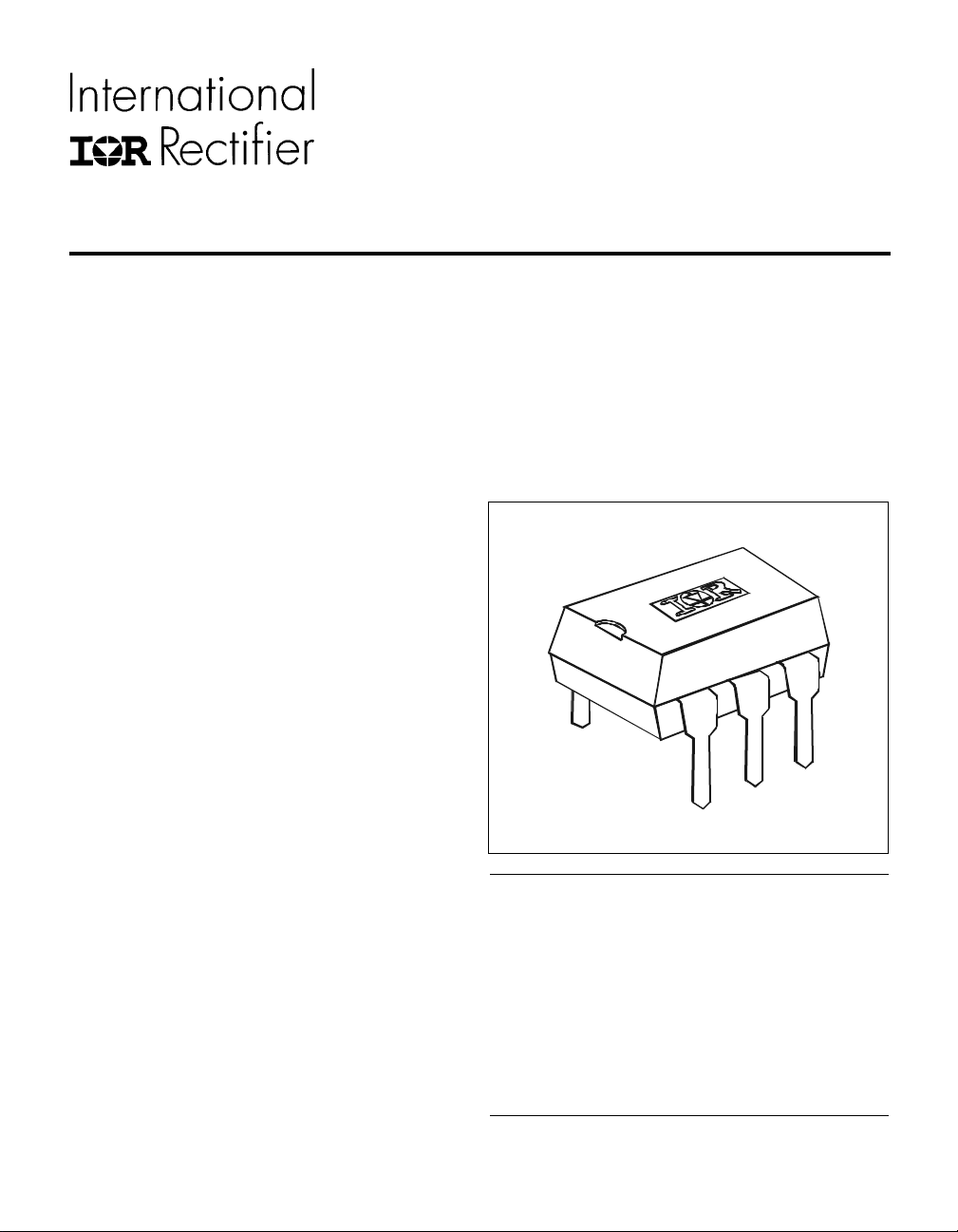
HEXFET® Power MOSFET Photovoltaic Relay
Next Data SheetIndex
Previous Datasheet
To Order
Single Pole, Normally Open, 0-400V, 140mA AC/DC
PD 6.040D
Series PVT412
Microelectronic
Power IC Relay
General Description
The PVT412 Series Photovoltaic Relay is a singlepole, nor mally open solid-state relay that can
replace electromechanical relays in many applications. It utilizes International Rectifier’s proprietary
HEXFET power MOSFET as the output switch,
driven by an integrated circuit photovoltaic generator of novel construction. The output switch is
controlled by r adiation from a GaAlAs light emitting
diode (LED) which is optically isolated from the
photovoltaic generator.
These SSRs are specifically designed for worldwide
telecom applications. PVT412L employs an active
current-limiting circuitry enabling it to pass FCC
Part 68 and other regulatory agency current surge
requirements when overvoltage protection is
provided. PVT412 does not employ the currentlimiting circuitry and offers lower on-state resistance.
Series PVT412 Relays are packaged in a 6-lead
molded DIP package with either through-hole or
surface mount (‘gull-wing’) terminals. It is available
in standard plastic shipping tubes or on tape-andreel. Please refer to part identification information
opposite.
PVT412L Features
HEXFET Power MOSFET output
Bounce-free operation
4,000 VRMS I/O isolation
Load current limiting
Linear AC/DC operation
Solid-State reliability
UL recognized and CSA certified
■■
■
■■
■■
■
■■
■■
■
■■
■■
■
■■
■■
■
■■
■■
■
■■
■■
■
■■
Applications
n On/Off Hook switch
n Dial-Out relay
n Ring relay
n General switching
(HEXFET is the registered trademark for International Rectifier Power MOSFETs)
Part Identification
PVT412L current limit, through-hole
PVT412LS current limit, surface-mount
PVT412LS-T current limit, surface-mount,
Tape and Reel
PVT412 no current limit, through-hole
PVT412S no current limit, surface-mount
PVT412S-T no current limit, surface-mount,
Tape and Reel
Series PVT412 HEXFET® Photovoltaic Relay
Next Data SheetIndex
Previous Datasheet
To Order
Electrical Specifications (-40°C ≤ TA ≤ +85°C unless otherwise specified)
INPUT CHARACTERISTICS Part Numbers Units
PVT412L PVT412
Minimum Control Current (see figures 1 and 2) 3.0 mA
Maximum Control Current for Off-State Resistance 0.4 mA
Control Current Range (Caution: current limit input LED, see figure 6) 3.0 to 25 mA
Maximum Reverse Voltage 7.0 V
OUTPUT CHARACTERISTICS
Operating Voltage Range 0 to ±400 V
Maximum Load Current @ T
5mA Control (see figures1 and 2)
Maximum On-State Resistance @T
For 50mA Pulsed Load, 5mA Control (see figure 4)
Maximum Off-State Leakage @TA=+25°C, ±400V (see figure 5) 1.0
Current Limit @T
Complies with FCC Part 68 Surge Requirements* yes yes
Maximum Turn-On T ime @T
For 50mA, 100 VDC load, 5mA Control 2.0 ms
Maximum Turn-Off Time @T
For 50mA, 100 VDC load, 5mA Control 0.5 ms
Maximum Thermal Offset Voltage @ 5mA Control 0.5 µV
Maximum Output Capacitance @ 50V
=+25°C, For 5mA Control Current:
A
=+40°C
A
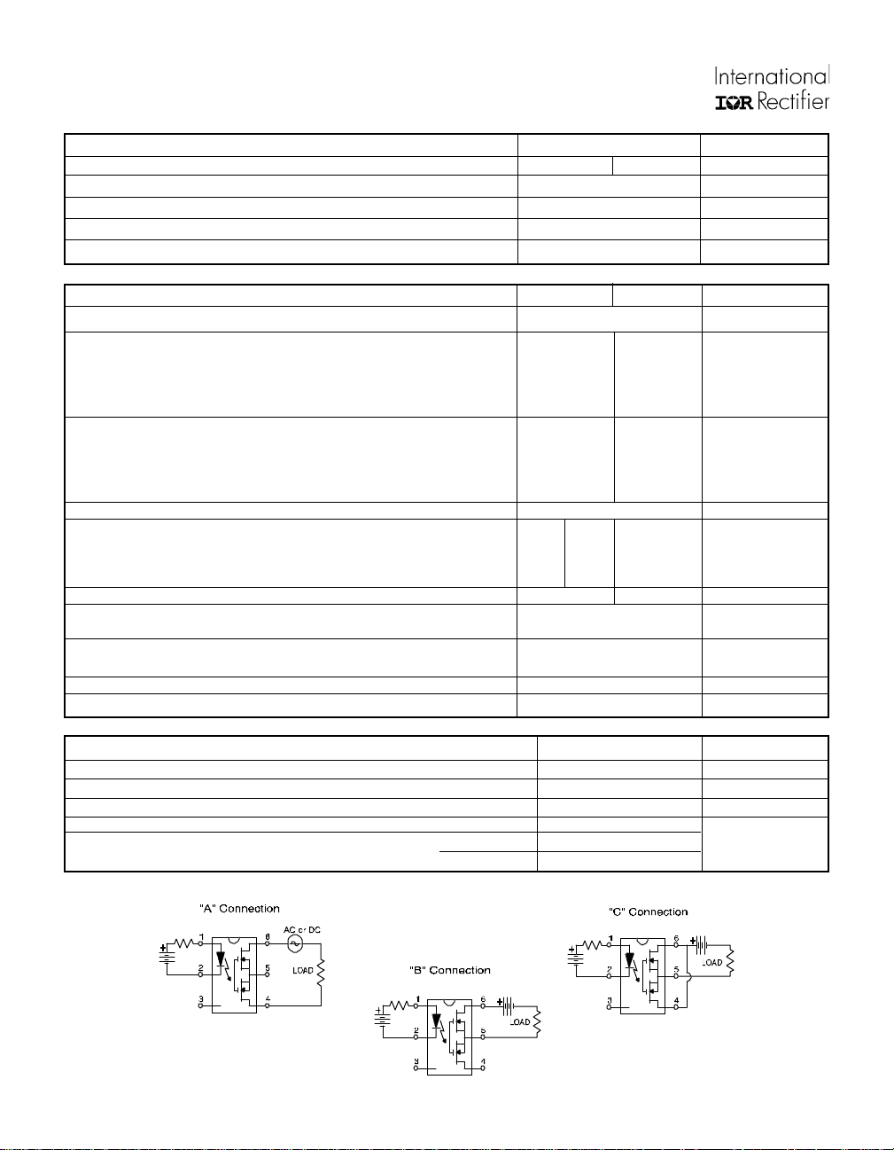
A Connection 120 140 mA (AC or DC)
B Connection 130 150 mA (DC)
C Connection 200 210 mA (DC)
A=+25°C
A Connection 35 27 Ω
B Connection 18 14 Ω
C Connection 9 7 Ω
Connection: AC
Minimum 130 260 n/a mA
Maximum 220 440 n/a mA
A=+25°C (see figure 7)
=+25°C (see figure 7)
A
DC
PVT412L PVT412
(DC or AC peak)
µA
12 pF
GENERAL CHARACTERISTICS ALL MODELS
Minimum Dielectric Strength, Input-Output 4000 V
Minimum Insulation Resistance, Input-Output @TA=+25°C, 50%RH, 100V
Maximum Capacitance, Input-Output 1.0 pF
Maximum Pin Soldering Temperature (10 seconds maximum) +260
Ambient Temperature Range: Operating -40 to +85 °C
Storage -40 to +100
DC
10
12
RMS
Ω
Connection Diagrams

Series PVT412 HEXFET® Photovoltaic Relay
Next Data SheetIndex
Previous Datasheet
To Order
I
LED=
I
LED=
A
A
Figure 1. Current Derating Curves*
200
PVT412
150
100
50
-5.0 -4.0 -3.0 -2.0 -1.0
1.0 2.0 3.0 4.0 5.0
-50
-100
-150
-200
PVT412L
5 mA control
@ 25°C pulsed
I
LED=
I
LED=
Figure 2. Current Derating Curves*
Figure 3. Linearity Characteristics
Figure 5. Typical Normalized Off-State Leakage
* Derating of ‘B’ and ‘C’ connection at +85°C will be 70% of that
specified at +40°C and is linear from +40°C to +85°C.
Figure 4. Typical Normalized
CAUTION: Provide
current limiting so that
25 mA max. steady-state
control current rating
is not exceeded.
Figure 6. Input Characteristics
On-Resistance
TYPICAL
min. device & +85°C limit
max. device & -45°C limit
(Current Controlled)

Series PVT412 HEXFET® Photovoltaic Relay
Next Data SheetIndex
Previous Datasheet
To Order
20
10
5
3
50 100
Delay Time (microseconds)
t
t
dlyton
off
200
50020 1000 2000
Figure 7. Typical Delay Times
I
LED
90%
10%
I
D
t
t
dly
off
t
on
Figure 8. Delay Time Definitions
Case Outline
Dimensions in millimeters (inches)
Mechanical Specifications:
1. Dimensioning and tolerancing per
ANSI Y14.5M-1982
2. Controlling Dimension: Inch
➃ Dimension does not include mold protrusions.
Mold protrusions shall not exceed 0.25 (.010).
Typical Capacitance (pF)
Figure 9. Typical Output
Capacitance
IR FAR EAST: K&H Bldg., 2F, 3-30-4 Nishi-Ikeburo 3-Chome, Toshima-Ku, Tokyo, Japan 171 Tel: ++ 81 3 3983 0641
IR SOUTHEAST ASIA: 315 Outram Road, #10-02 Tan Boon Liat Building, Singapore 0316 Tel: ++ 65 221 8371
Note: PVT412L relays will pass FCC Part 68 surge current requirements operating
into rated load or short circuit when protected from overvoltage by a transient protection device such as a 175 VRMS rated MOV placed between the tip and ring terminals of the telephone line or across the output of the relay. PVT412 relays will
pass the above FCC Part 68 requirements when overcurrent protection devices (such
as fusible resistors) are placed in series with tip and ring lines in addition to the
aforementioned overvoltage protection. Consult factory for additional information.
WORLD HEADQUARTERS: 233 Kansas St., El Segundo, California 90245, Tel: (310) 322 3331
EUROPEAN HEADQUARTERS: Hurst Green, Oxted, Surrey RH8 9BB, UK Tel: ++ 44 1883 713215
IR CANADA: 7321 Victoria Park Ave., Suite 201, Markham, Ontario L3R 2Z8, Tel: (905) 475 1897
IR GERMANY: Saalburgstrasse 157, 61350 Bad Homburg Tel: ++ 49 6172 96590
IR ITALY: Via Liguria 49, 10071 Borgaro, Torino Tel: ++ 39 11 451 0111
Data and specifications subject to change without notice.
http://www/irf.com/
9/96
 Loading...