

International Rectifier IRDCiP2001-B Reference Design
R
Overview
In this document, table 1 and figure 1 are provided to enable engineers to
easily evaluate the iP2001 in a 3-phase configuration that is capable of
providing up to 60A in a lab environment without airflow. Figures 3, 4, 5 and
6 and the complete bill of materials in table 2 are provided as a reference
design to enable engineers to very quickly and easily design a 3-phase
converter. In order to optimize this design to your specific requirements
refer to the data sheet for the controller listed in the bill of materials. A variety
of other controllers may also be used, but the design will require layout and
control circuit modifications.
Demoboard Quick Start Guide
Initial Settings:
z The output is set to 1.7V, but can be adjusted from 1.1 to 1.85V by setting
z The switching frequency per phase is set to 500kHz with the frequency set resistor R4. This creates an effective
Procedure for Connecting and Powering Up Demoboard:
1. Apply input voltage (5-12V) across VIN (TP18) and PGND (TP14). Note that this input source must be applied first during
2. Apply +5V logic power across +5V (TP19) and PGND (TP20).
3. Apply load across VOUT pads (TP10 - TP12) and PGND pads (TP14 - TP16)
4. Set ENABLE high.
5. Monitor switch node signals (optional) via TP6 - TP8.
6. Adjust load accordingly.
EFERENCE
R
EFERENCE
International Rectifier • 233 Kansas Street, El Segundo, CA 90245 USA
IRDCiP2001-B, 500kHz, 60A, 3-phase Synchronous Buck
S1 according to the VID codes provided in Table 1. Droop control is set to 50mV at 60A, but can be adjusted by
following the instructions in the data sheet for the PWM controller.
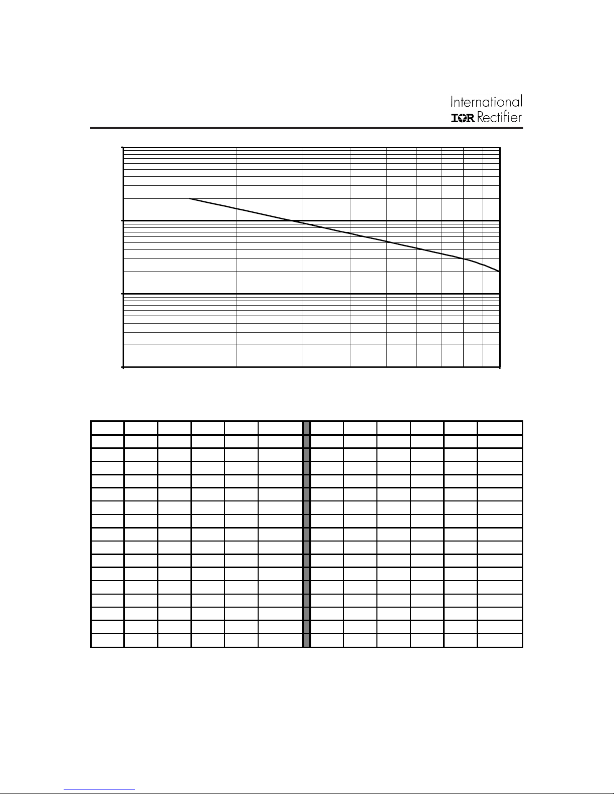
output frequency of 1.5MHz. The graph in figure 1 shows the relationship between R4 and the switching frequency
per phase. This frequency may be adjusted by changing R4 according to this graph; however, extreme changes
from the 500kHz set point may require redesigning the control loop and adjusting the values of input and output
capacitors. Also, refer to the SOA graph in the iP2001 datasheet for maximum operating current at different
frequencies.
the power-up sequence.
D
D
Converter using iP2001
ESIGN
ESIGN
IRDCiP2001-B
iP2001 Recommended Operating Conditions
(refer to the iP2001 datasheet for maximum operating conditions)
Input voltage: 5 - 12V
Output voltage: 1.1 - 1.85V
Output current: 20A per phase, 60A total for 3-phase demo board.
Switching Freq: 500kHz per phase, 1.5MHz effective output frequency.
07/19/02
IRDCiP2001-B
1000
100
)
Ω
Resistance (k
10
1
100 1000
Output Frequency (kHz)
Figure 1 - R4 vs. Frequency per Phase
VID4 VID3 VID2 VID1 VID0 VDAC VID4 VID3 VID2 VID1 VID0 VDAC
11111 Off 011111.475
111101.100 011101.500
111011.250 011011.525
111001.150 011001.550
110111.175 010111.575
110101.200 010101.600
110011.225 010011.625
110001.250 010001.650
101111.275 001111.675
101101.300 001101.700
101011.325 001011.725
101001.350 001001.750
100111.375 000111.775
100101.400 000101.800
100011.425 000011.825
100001.450 000001.850
Table 1 - PWM IC Voltage Identification Codes
www.irf.com2
IRDCiP2001-B
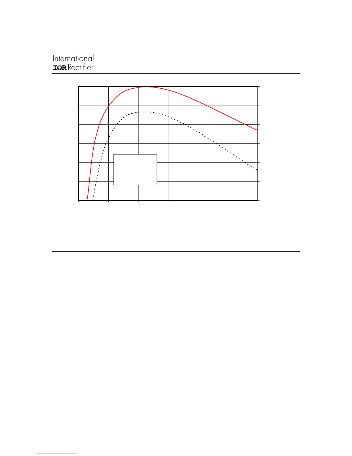
92%
90%
88%
fSW= 500kHz
86%
VIN = 12V
= 1.6V
V
OUT
= 25°C
T
A
0 102030405060
fSW= 1MHz
84%
82%
80%
Efficiency
Output Current (A)
Figure 2 - Typical Efficiency vs. Current
Refer to the following application notes for detailed guidelines and suggestions when
implementing iPOWIR Technology products:
AN-1028: Recommended Design, Integration and Rework Guidelines for International Rectifier’s
iPOWIR Technology BGA Packages
This paper discusses the assembly considerations that need to be taken when mounting iPOWIR BGA’s
on printed circuit boards. This includes soldering, pick and place, reflow, inspection, cleaning and
reworking recommendations.
AN-1029: Optimizing a PCB Layout for an iPOWIR Technology Design
This paper describes how to optimize the PCB layout design for both thermal and electrical performance.
This includes placement, routing, and via interconnect suggestions.
AN-1030: Applying iPOWIR Products in Your Thermal Environment
This paper explains how to use the Power Loss and SOA curves in the data sheet to validate if the
operating conditions and thermal environment are within the Safe Operating Area of the iPOWIR product.
www.irf.com 3
 Loading...