

International Microsystems M6310, M6320, M6330, M6340 User Manual
THE M6310/20/30/40 USB DUPLICATOR
International Microsystems Incorporated
M6310/20/30/40 USB Flash Drive
Duplicator Manual
Version 1.9
1

2

THE M6310 FLASH DRIVE DUPLICATION SYSTEM
Copyright ©2008-2010 International Microsystems, Inc. All rights reserved.
International Microsystems, Inc.
556 Gibraltar Drive
Milpitas, CA 95035
U.S.A.
Telephone: 408-942-1001
FAX: 408-942-1051
Email: sales@imi-test.com
Website: www.imi-test.com
Manual Version: 1.9 on Sep 16, 2010
Information in this manual is subject to change without notice and
does not represent a commitment on the part of the vendor.
3

THE M6310 FLASH DRIVE DUPLICATION SYSTEM
4

THE M6310 FLASH DRIVE DUPLICATION SYSTEM
Table of Contents
1 Introducing the M6310 USB Duplication Systems .............................................. 7
1.1 M6310 Power Up and Power Down ................................................................................................. 7
1.2 M6310 Basic Operation- Getting Started with a Simple Copy ......................................................... 8
1.3 Performing Software Updates .......................................................................................................... 9
1.4 Calibration ...................................................................................................................................... 11
2 M6310 Features .................................................................................................... 12
2.1 Disk Organization and Binary Image Copy (Verify) ....................................................................... 12
2.2 Create Master Image File............................................................................................................... 13
2.3 Smart Copy (Verify) ........................................................................................................................ 13
2.4 Smart Create Master File ............................................................................................................... 14
2.5 Format ......................................................................................................................................... 14
2.6 Files Copy (Verify) .......................................................................................................................... 14
2.7 Logging ......................................................................................................................................... 14
2.8 Kiosk Mode .................................................................................................................................... 14
2.9 Barcode ......................................................................................................................................... 14
2.10 The M6310 Keyboard and display ................................................................................................. 15
2.11 Run Job ......................................................................................................................................... 16
2.12 Use of USB Flash Adapters with the M6310.................................................................................. 17
2.13 Using the Run Job Menu – A Simple USB Duplication Example .................................................. 17
2.14 Front Panel Loop Run Job ............................................................................................................. 18
2.15 Front Panel Information .................................................................................................................. 19
2.16 Front Panel Shut Down .................................................................................................................. 19
3 M6310 Technical Description .............................................................................. 20
3.1 M6310 Multi-Slice Connections ..................................................................................................... 20
4 M63W – The M6310 Graphical User Interface (GUI) .......................................... 22
4.1 Starting the M6310 Graphical User Interface (GUI) ....................................................................... 22
4.1.1 File Menu ............................................................................................................................ 24
4.1.2 Connection Menu ................................................................................................................... 24
4.1.3 Admin Menu ........................................................................................................................... 24
4.1.4 Tools Menu ............................................................................................................................ 25
4.1.5 Help Menu ............................................................................................................................ 26
4.2 Operation Modes and Password Editing ........................................................................................ 26
4.3 M6310 Configuration ...................................................................................................................... 26
4.3.1 Set Default mode .................................................................................................................... 27
4.3.2 Auto Sync ............................................................................................................................ 27
4.3.3 Auto Start Fully Loaded .......................................................................................................... 27
4.3.4 Slice configuration .................................................................................................................. 27
4.4 Job Creation and Editing ................................................................................................................ 27
4.4.1 Fully Loaded Check ................................................................................................................ 28
4.5 Adding New Operations and Setting Operation Parameters ......................................................... 29
4.6 Set Values Operation Parameters ................................................................................................. 30
4.7 Set LUN (Logical Unit) Parameters ................................................................................................ 32
4.8 Create Master Image File............................................................................................................... 32
4.9 File Copy (Verify) ........................................................................................................................... 34
4.10 Check Device Config ...................................................................................................................... 35
4.11 Speed Test ..................................................................................................................................... 36
4.12 TCL Command ............................................................................................................................... 37
5

THE M6310 FLASH DRIVE DUPLICATION SYSTEM
4.13 Update GUID .................................................................................................................................. 37
4.14 Target Backup and Restore ........................................................................................................... 38
4.15 Saving a New or Edited Job ........................................................................................................... 38
4.16 Display Information ........................................................................................................................ 39
4.17 Checksum Master Device .............................................................................................................. 40
4.18 Barcode Setup ............................................................................................................................... 41
4.19 Tips for Duplication ........................................................................................................................ 44
5 M6310 GUI Job Execution ................................................................................... 45
5.1 Execution of a Simple Job ............................................................................................................. 45
5.2 Starting the Job .............................................................................................................................. 46
5.3 Job Completion .............................................................................................................................. 46
5.4 Log Viewer ..................................................................................................................................... 48
6 Creation of USB Drives with Multiple LUN’s or Partitions ................................ 49
6.1 Introduction .................................................................................................................................... 49
6.2 M6310 Support of Different USB Controllers ................................................................................. 49
6.3 SMI 325 & 3255AB Support ........................................................................................................... 49
6.4 Example – Two LUN’s with LUN0 R/W and LUN1 Read Only ...................................................... 49
6.4.1 OP1: USB Controller .............................................................................................................. 51
6.4.2 OP2: Set LUN ......................................................................................................................... 51
6.4.3 OP3: Set Values ..................................................................................................................... 52
6.4.4 OP4: Designated Operation for LUN0 (e.g. Program-Verify, Smart Program-Verify etc.) ..... 52
6.4.5 OP5: Set LUN ......................................................................................................................... 52
6.4.6 OP6: Set Values ..................................................................................................................... 53
6.4.7 OP7: Operation (e.g. Program-Verify, Smart Program-Verify etc.) ........................................ 53
6.4.8 OP8: USB Controller .............................................................................................................. 53
6.5 Example: A USB Drive with a single CD-ROM Partition ................................................................ 54
6.5.1 OP1: USB Controller .............................................................................................................. 55
6.5.2 OP2: Set Values ..................................................................................................................... 56
6.5.3 OP3: Designated Operation (e.g. Program-Verify) ............................................................... 56
6.5.4 OP4: USB Controller .............................................................................................................. 56
6.6 Example: Removing Multiple Partitions from a USB Drive ............................................................ 56
6.7 Formatting a USB Drive ................................................................................................................. 57
6.8 Cleaning a USB Drive .................................................................................................................... 58
6.9 Change USB Drive Information ...................................................................................................... 59
6.10 Phison Controller ............................................................................................................................ 60
7 Running Multiple M6310 Slices: M6320, M6330, M6340 .................................... 61
7.1 Setting Up the System Hardware ................................................................................................... 61
7.2 Checking/Changing the System Configuration .............................................................................. 62
7.3 Setting up the Multi-Slice Configuration ......................................................................................... 63
8 Setting the M6310 Host Name and IP Address .................................................. 65
8.1 Network Administration .................................................................................................................. 65
8.2 YAST Settings ................................................................................................................................ 65
9 Configuring M6310 to a user network ................................................................ 68
9.1 Recommended Topology for User Network Access ...................................................................... 68
9.2 Adding a User IP address using the Linux YAST Program ........................................................... 69
9.2.1 YAST setting .......................................................................................................................... 69
9.3 Configuring the new IP for user access to Postgres database ...................................................... 71
9.4 Testing the new Network connection ............................................................................................. 71
6

THE M6310 FLASH DRIVE DUPLICATION SYSTEM
1 Introducing the M6310 USB Duplication Systems
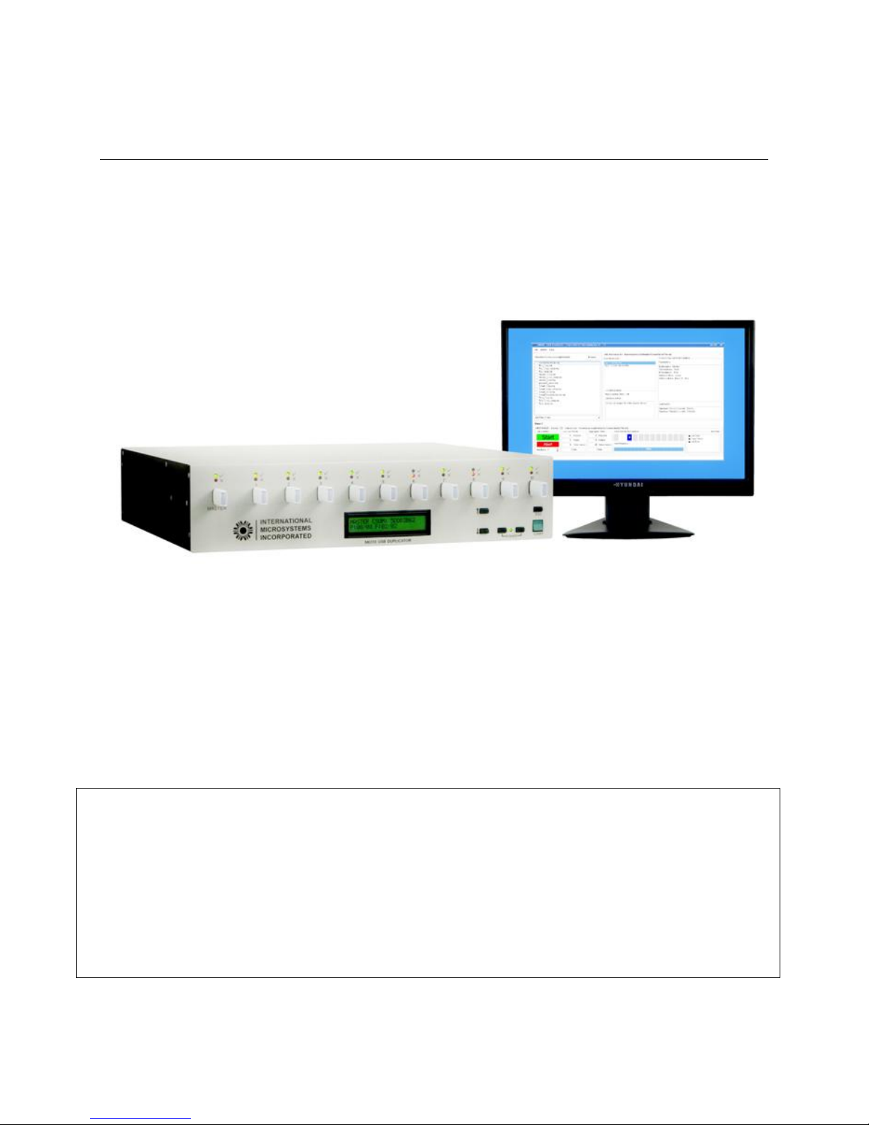
Figure 1-1 The M6310 Front Panel
The M6310 USB duplicator provides high quality duplication for USB 1.1 and 2.0 Flash
drives. The M6310 is a fully featured Linux computer with a large removable 3.5” hard
drive, LCD monitor, PC keyboard, and mouse. In addition, the M6310 has a 2x24 LCD
front panel LCD and five front panel control keys; namely, UP, DOWN, ESC, and two
power ON/OFF keys. For the power control keys to be active, both keys must be
pushed simultaneously.
The M6310 supports a number of different operational modes that allow the user to
optimize his production workflow. In addition, multiple M6310’s of up to four units can
be networked together to support a single copy station with 20, 30, or 40 copy slots.
This section discusses using the M6310 as a standalone duplicator run solely from its
front panel controls. Operation from a LCD monitor along with the PC keyboard and
mouse will be discussed in a later chapter.
1.1 M6310 Power Up and Power Down
Before powering up the M6310, make sure that the LCD monitor, PC keyboard, and
mouse are connected to the M6310 base unit and the power cords for the M6310 and
LCD monitor are plugged into an AC socket. If the M6310 is going to be used as a
standalone duplicator, only the power cords needs to be connected to the M6310 base
unit.
The M6310 uses a special method of power up so that the operator does not
accidentally power down the instrument while performing duplication functions. Turning
7

THE M6310 FLASH DRIVE DUPLICATION SYSTEM
on the M6310 requires the simultaneous momentary depression of the two front panel
switches labeled “Power”.
After the power is turned on, the M6310 will take about one minute to configure the
machine, place its power up screen on LCD display, and sound a short sequence of five
notes.
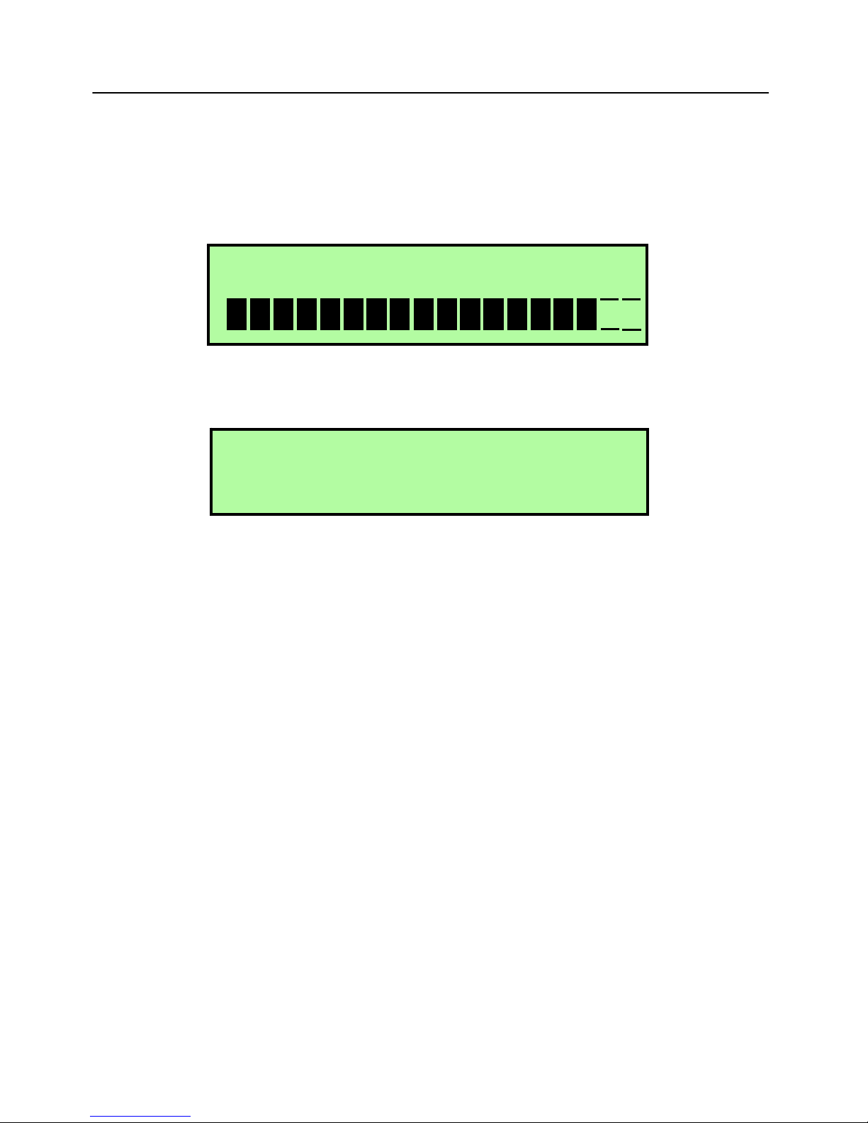
Figure 1-2 M6310 Power UP Screen
At the completion of the boot process, the LCD monitor screen will appear as in Figure
1-2 above.
There are three options for shutting down a M6310.
Shutdown Method 1: This is the preferred method using the LCD Monitor. Exit the
M6310 GUI. Then Click on the Linux “Start” menu, which is located at the lower left
corner. Then select “Shutdown Computer” in the “Leave” tab. This will shut down the
M6310 properly.
Shutdown Method 2: This is the preferred method in standalone mode
ESC key until the LCD display shows “RUN Job”. Using the down cursor, go down until
the operation displayed is “Shut Down”. Press the Green Start button twice to select
and to confirm the command and the M6310 will power down.
Shutdown Method 3: Do not use this method unless method 1 and 2 cannot be
used. Shutting down the M6310 using the front panel Power Keys may damage
the M6310 file system and cause operational problems.
Using the two Power keys, press both together and hold down until the M6310 shuts
down. Release the Power keys as soon as the M6310 LCD turns off. If you continue to
hold these keys down, you will inadvertently power up the system.
. Press the
1.2 M6310 Basic Operation- Getting Started with a Simple Copy
8

THE M6310 FLASH DRIVE DUPLICATION SYSTEM
Start the power on sequence by simultaneously pressing and then releasing the two
power keys on the M6310 front panel. The M6310 power led will light up and the LCD
monitor will show a standard Linux boot sequence. The Linux boot usually takes about
one minute.
Various types of functions can be run on the M6310 that are selectable using the front
panel keypad. When using the M6310 front panel, the data source for the ten copy
sockets is normally a Master USB flash drive placed in the M6310 MASTER drive
socket which is the first socket on the left side of the duplicator. The basic operation is
to place the Master USB drive in the M6310 slot labeled MASTER, fill the ten copy slots
with ten USB drives that are identical to the MASTER drive except for their content, and
start a copy program on the M6310 that copies all the data on the USB drive in the
Master slot to the ten USB drives in the copy slots.
Example of a Binary Image Copy from a Master USB Drive:
1. Place a Master USB drive in the Master M6310 slot (far left).
2. Place from one to ten USB drives that are identical (same size and manufacturer)
in the M6310 copy slots labeled 1-10.
3. The second line of the front panel display will read “ Run Job”. Select this
operation by momentarily pressing the Green Start Key on the right.
4. Using the down cursor keys, cursor down until the display reads “Copy with
Verify”.
5. Momentarily, Press the Green Start Key. The USB drive copy function will start
and the data from the Master USB drive will be copied to the copy drives followed
by a verify operation that verifies, in parallel mode, each bit of the Master USB
drive against the data in each and every copy drive.
1.3 Performing Software Updates
** M6310: SW Ver 1.58 **
→RUN Job ↓
Main Menu, Starting point. Cursor down until Software Update is displayed.
Information ↑
→Software Update ↓
From the main menu scroll down and select “Software Update” using the Start Key.
9

THE M6310 FLASH DRIVE DUPLICATION SYSTEM
Please insert the USB
→Drive in Master Slot. ↓
After selecting Software Update “Please insert the USB Drive in Master Slot” will be
displayed. Insert the IMI USB update drive into the Master slot and wait until the green
LED blinking then push the Start key.
Note:
The USB drive used may be supplied by the user and the Software Update can be
obtained from the IMI website “ www.imi-test.com “ or through IMI technical support.
Select an update (1)
→M6310_158.zip ↓
The “Select an update” menu will be displayed. Select the update file provided on the
IMI USB update drive and push the START button; this will complete the Software
Update, (please note that there may be more then one file on the supplied IMI USB
drive to select from, so please follow the instructions provided).
Press START or ESC
→to Restart Server
The M6310 will display “Press START or ESC to Restart Server”. You will hear two
audible beep tones indicating the M6310 server is shutting down.
SERVER DOWN.
The M6310 update will be performed and “SERVER DOWN” displayed on the LCD for a
few seconds. After the server is restarted, the main menu will be displayed on the LCD.
10

THE M6310 FLASH DRIVE DUPLICATION SYSTEM
** M6310: SW Ver. 1.58**
→Run Job ↓
To verify the update after the restart cycle is completed; check the first line of the LCD
display the Software update revision is displayed; example: “M6310: SW Ver. 1.58”.
1.4 Calibration
There is no need for the M6310 to be calibrated after initial shipment. Your internal
company policies may require calibration and if this is the case, IMI can optionally
provide this service upon request. Please check your organization’s specific calibration
policies.
11

The M6310 USB Flash Drive Duplication System
2 M6310 Features
2.1 Disk Organization and Binary Image Copy (Verify)
USB Drives are similar to standard hard drives used in computer systems. A USB drive
has two main hardware elements; namely a controller, which is a microcomputer and
memory consisting of FLASH memory chips. The Flash memory is divided into two main
sections; namely a section of Flash used to hold the controller program and a section
used for storing the drive file information.
The Flash memory used to hold the drive file information is divided up into equal blocks
of which the smallest is called “sectors” which are each typically 512 bytes of data.
Sectors are organized into groups that are dependent upon how the user wishes to use
the drive. If the data is to be stored in RAW format, the drive consists only of sectors.
However, if the drive is to be used with a standard computer such as a WIN PC, the
sectors will be organized in the following manner.
Sector 0 (The Boot Block Sector): The boot block sector that contains information about
the drive (size, organization, maker, etc.).
Partition Table: The sectors of the drive may be divided up into one or more logical
drives which are referred to as Partitions and the Partition Table describes this
segmentation. Multiple Partitions on the same drive may have different types of File
organizations; for instance, Partition 0 may be FAT32 and Partition 1 may be NTFS.
FAT Tables: Each Partition will have a File Allocation Table, which is a table that
describes the Data Files that are stored in the given Partition.
Data Files: The User files that store the user information.
It is important that the user have an understanding of the above organization if he
wishes to copy USB drives correctly. Depending upon the type of formatting of the
Drive, the organization and data in Sector 0, the Partition Table, the FAT Tables,
and the Data Files, may be different for the same stored information.
Because there are many ways to organize the data stored in the sectors of the USB
drive, the simplest and safest method of copying employed by the M6310 is to start
copying the Master drive at sector 0 and continue copying all sectors until either the end
of the drive is reached or until the end address which is chosen by the user. This
method is called the Binary Image Copy Method and when employed by the user,
ensures that copy drives will be exactly the same as the Master drive (or Master Image).
Note that a Binary Image Copy will not only copy the Master drive data files, but also the
boot sector, partition tables, and fat tables.
M6310 also supports copying USB drives with multiple LUN’s. Duplication of USB
drives with multiple LUN’s is done using the M6310 GUI and will be discussed in a later
section.
12

The M6310 USB Flash Drive Duplication System
By default, a M6310 verify normally is performed on the whole device or the specified
range. Optionally, the user can choose to verify only a certain percentage of the whole
device or the specified range of sectors.
2.2 Create Master Image File
M6310 can use either a master device or a master binary image file as the source
during the duplication. The master binary image file is a pure binary file. To create a
master image file, the Create Master Image file operation is used. User has the option
to save either the content of the whole device or a particular range of sectors.
2.3 Smart Copy (Verify)
In addition to Binary Copy, the M6310 employs a method of copying that we refer to as
Smart Copy. Smart Copy (Verify) uses IMI proprietary techniques to determine the
size of the data to be worked on. When using the Smart Copy operations, the master
device should be formatted using FAT, FAT32, NTFS, Linux, or HFS+ file systems. If
your master USB drive does not use one of these file systems, then you should NOT
use the Smart version of the operations. Also, although IMI strives to support all
versions of the stated file systems, IMI cannot guarantee that its Smart Copy
operations will work correctly 100% of the time. Therefore, it is up to the user to
verify that a Smart Copy operation has correctly copied the desired master data.
If the user cannot verify that the Smart copy operation is correct, then the Binary
Image copy method should be used.
Smart operations on FAT or FAT32 read the information in the boot block and FAT
system that normally appear in the lowest (beginning) LBA of the Master device. From
this, the end location of the active data is determined. Thus with a starting address of
Zero, and an end address of the last used block on the master drive, the M6310 can
calculate an end address which should adequately include the last data of the file
system to be copied. Smart Copy operations on other file systems require complex
analysis of the specific file system organization which result in a table of used sectors
on the master drive that are selectively copied.
By default, the Smart Verify operation performs a bit by bit verify on the sectors copied
during the Smart Copy operation. Optionally, the user can chose to verify only a certain
percentage of the sectors selected.
If the data source is a master device with multiple partitions of which one or more of the
partitions contain a non-supported file system, an invalid file system, or an extended
partition, the user can select the “Ignore Invalid FS” option and this area will be copied
using the Binary Image Copy method.
13

The M6310 USB Flash Drive Duplication System
2.4 Smart Create Master File
The Smart master image file is a binary image file with a IMI proprietary Smart Copy
header. The header contains the information supporting IMI Smart Copy operations
such as size and location of the copy data. The operation detects and validates the file
system automatically. If there are any unsupported or invalid file systems in the device,
the operation will be failed. User has an option to save the data of an invalid file system
or the extended partition. This operation supports multiple partitions as well as multiple
LUN’s. A Smart master file only works with the Smart Copy and Verify operations.
Please don’t use a Smart master image file with a Binary Image Copy operation.
2.5 Format
The duplicator can format USB drives in the 1-10 copy slots as FAT, FAT32, NTFS, or
Linux but it cannot format the device to multiple partitions. This operation performs
sequentially not in parallel.
2.6 Files Copy (Verify)
The devices have to be formatted as FAT, FAT32, NTFS, or Linux and the device can
only have a single partition. M6310 can copy a file, many files, or directory. The
verification is done by the md5 checksum. This operation performs sequentially not in
parallel. Therefore it is not recommended for copying large data files.
2.7 Logging
A type of database called PostgreSQL is installed in each M6310 duplicator. The
database stores the job information such as start time, end time, job name, and
information of the devices such as the serial number, VID, PID, capacity, and etc.
M6310 logs the information of all devices at the end of duplication regardless the job is
launched from the keypad or from the GUI.
2.8 Kiosk Mode
Kiosk mode is the same as asynchronous mode. Once a device is inserted, the
duplication will be started automatically. The data source has to be the binary image file
or smart binary image file. Different slots can be assigned to different image files. This
mode supports single operation only.
2.9 Barcode
Using the M6310 Barcode option is simple way for the operator to start a M6310
duplication job. This feature allows the supervisor to setup a barcode job file, which
includes the M6310 job name, the target quantity, and optionally the operator name. If
the Barcode feature is enabled, the operator will be asked to enter (to scan) the name of
barcode job file when the GUI starts. The operator cannot change any information.
14
The M6310 USB Flash Drive Duplication System
When the target quantity is set and the total pass is equal or greater than the target
quantity, a dialogue box will be shown to alert the operator.
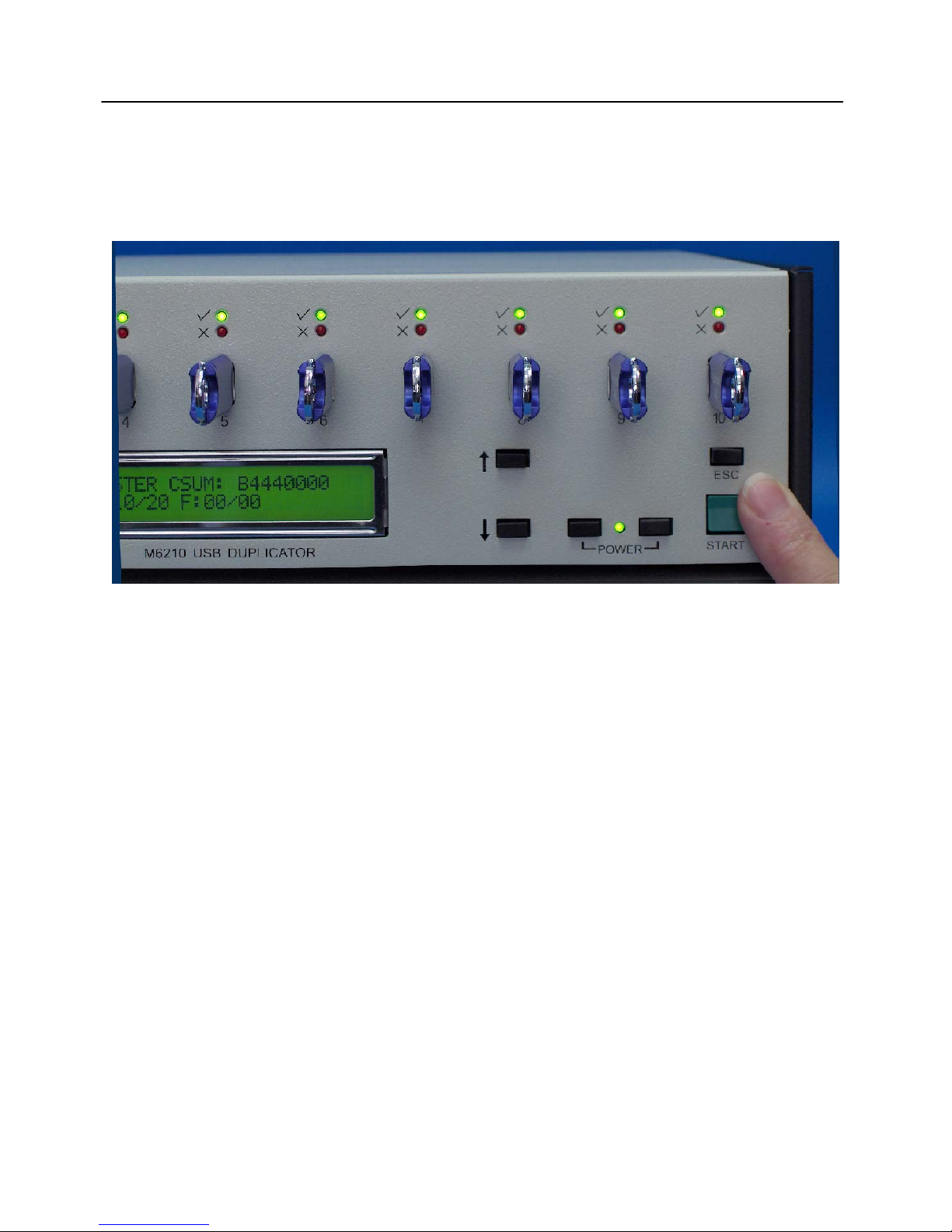
2.10 The M6310 Keyboard and display
Figure 2-1: Front Panel Display and Keyboard
The M6310 can be controlled completely from its front panel keyboard and LCD (see
Figure 2-1 above). The keys consist of the following:
Two Cursor Keys: Up and Down for choosing a Selected Function.
An Esc Key backing up in a Selection Process or leaving the current function to return
to the top Menu.
Two Power On/Off Keys for initial power on and hardware power off. These keys are
only active if both keys are pressed at the same time.
One Green START Key used to initiate a function or repeat a process.
The LCD is a two line, 24 character display.
To power up the M6310, the user plugs in the female end AC power into the lower right
rear of the M6310 and the male end into an AC power receptacle, then momentarily
presses the two Power Keys at the same time. The LCD screen will light up and about
one minute later, the initial M6310 power on Screen will appear as in Figure 2-1. The
top line of the LCD will show the current software version of the M6310. The second
Line of the LCD will show the Current Function that can be selected using the START
Key.
15

The M6310 USB Flash Drive Duplication System
If the user wishes to select a different keyboard function, he/she may press the cursor
Down arrow. The possible initial functions selectable from the top menu are:
Run Job
Loop Run Job
Information
Software Update
Shut Down
2.11 Run Job
Run Job presents a list of currently defined Jobs in the default directory which is defined
in the “/home/imi/config/gui.ini” file. The default front panel Job directory is
“/home/user/script/defaults”. The default directory can be changed in the GUI. The
front panel Job List may be edited using the M6310 GUI program.
To select a Job from the Job List under Run Job, Press the START Key when Run Job
is displayed on the LCD screen.
The default Job List shipped with a new M63l0 in this list are shown as Jobs created in
the M6310 GUI and have the extension “mlj’.
Copy_From_File Copies from a Defined File to the copy Drives
File_Copy_Verify Copies from a Defined File to the Copy Drives then
Verifies The File Against the Copy Drives
Master_Copy Copies the Entire Master Drive to the Copy Drives
Master_Copy-Verify Copies the Entire Master Drive to the Copy Drives then
Verifies The Master Drive against the Copy Drives
Master_Verify Verifies The Master Drive against the Copy Drives
Smart_Copy Copies the Fat Content of the Master Drive to the Copy
Drives (see section 3.3 Smart Copy for more information)
Smart_Copy_Verify Copies the Fat Content of the Master Drive to the Copy
Drives then Verifies the Fat Content of The Master Drive
against the Copy Drives
Smart_Verify Verifies The Fat Content Master Drive against the Copy
Drives
Test_Copy Copies a Test Pattern (TR3) to the Copy Drives
Test_Copy_Verify Copies a Test Pattern to the Copy Drives then Verifies
16

The M6310 USB Flash Drive Duplication System
The Test Pattern against the Copy Drives
Test_Verify Verifies The Test Pattern against the Copy Drives
2.12 Use of USB Flash Adapters with the M6310
A USB card reader is an adapter used to read and write Flash memory media such as
Secure Digital cards. Most USB adapters can be used with the M6310 but IMI cannot
guarantee that all readers will work with all types of inserted Flash media. Please note
that the same rules for successful duplication apply; All USB adapters should be the
same manufacturer and model. All Flash Memory cards (master and copy cards) should
be from the same manufacturer and be of the same type and size (if possible,
purchased in trays).
To choose one of the above functions, use the Up and Down cursor keys followed by
the START key.
2.13 Using the Run Job Menu – A Simple USB Duplication Example
1. Upon Power up, the M6310 displays the following message on the LCD:
**M6310: SW Ver 1.-- **
→Run Job ↓
2. Load a Master drive in the MASTER slot and Copy drives in the Copy Slots.
Press the START key to select the Run Job menu.
Select a script
→Master Copy ↓
3. Press the Down arrow to locate the job Master Copy-Verify script:
Master Copy
→Master Copy-Verify ↓
17
The M6310 USB Flash Drive Duplication System
4. Press the START key to select and again to execute the Master Copy-Verify
Job.
5. Activity Bars will be displayed during the program and verify sections.
Program
6. Upon completion of the Job, a summary screen with pass and fail results is
displayed.
MASTER CSUM: D4280000
P:10/10 F:00/00
The above screen shows that the Master Card Checksum is the Hex number
D4280000. This checksum is the simple sum of all bytes in the Master Card that have
been copied to the Copy Cards.
After the selected operation is completed the Pass and Fail results of the last cycle are
displayed with the summary of all total Pass and Fails shown after the slash (/).
To start the next cycle; the user should remove all the devices and fill the duplication
slots with blank devices and press the Start to begin execution of the previously
selected job once again.
2.14 Front Panel Loop Run Job
Loop Job allows multiple execution of a selected Job. This function used for extensive
testing of devices as in a burn-in test. To loop run a job, see the instructions below.
1. Select Loop Run Job from the Main Menu.
2. Select the desired job.
3. When prompted for the number of loop, enter the desired number to run.
4. To enter the loop number, use up and down keys to select a number 1 through 9.
5. Press the START key one time to move to the next decimal place use up and down
keys to select a number 0 through 9 until the desired number of loops is indicated.
6. Press the START a second time to start the test.
18

The M6310 USB Flash Drive Duplication System
2.15 Front Panel Information
When the front panel Information is selected, M6310 network information is displayed
which is the M6310 IP address, and MAC address.
Network Information?
→IP: 192.168.5.2 ↓
Press the Down arrow to see the MAC address:
IP: 192.168.5.2
→MAC da:b7:7d:2c:d9:05
2.16 Front Panel Shut Down
The last option in the main menu is Shut Down. Select Shut Down from the main menu.
Information
→Shut Down ↓
Press the START key to shut down the unit (you will be prompted to verify the shutdown
command)
Shutdown are you sure?
YES=START NO=ESC
19

The M6310 USB Flash Drive Duplication System
3 M6310 Technical Description
3.1 M6310 Multi-Slice Connections
M6310 -MASTER SLICE
ETHERNET
M6310 - SLICE 2
ETHERNET
M6310 - SLICE 3
M6310 - SLICE 4
ETHERNET
ETHERNET
KVM
KVM
KVM
KVM
3
3
3
4 X 1
3
ETHERNET
5 PORT SW
K V M
4 X 4
4 X 3
LCD DISPLAY
KEYBOARD M
Figure 3-1: Four Slice M6310-40
Figure 3-1 shows a standard M6310-40 with a standard M6310-CAB. There are four
separate M6310’s, each with one master socket and ten copy sockets. They are
networked together using a 1 Gigahertz Ethernet switch, which is a part of the M6310CAB.
Each of the four M6310’s is an individual Linux computer, which on boot automatically
launches the M6310 Server program. When the M63W GUI program is launched and
correctly configured, all four M6310 slices can be controlled by the M63W GUI running
on the Master slice.
The four-device KVM in the M6310-CAB allows the user direct access to each of the
M6310 slices. However, normally, the user sets the KVM on the Master Slice only.
The software connecting the M6310’s are TCL scripts which use what is called a
“network socket” connection. When a user executes a Job created either by the M63W
GUI or by a text editor, the resulting TCL script will execute on all selected slices in
parallel.
20
The M6310 USB Flash Drive Duplication System
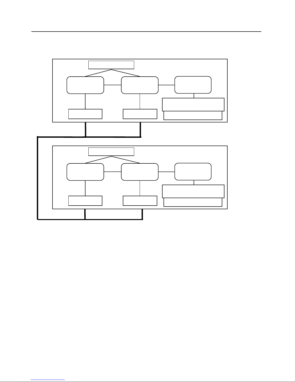
Figure 3-2 shows the software setup in a two slice M6310-20 configuration.
M6310 TCL Script
M6310 Master Slice
M63W
GUI
Wish
tttt
Interpreter
M6300
Server
Network Socket Network Socket
10 USB Host Sockets
M6300 TCL Script
M6100 Slice 2
M63W
GUI
Wish
tttt
Interpreter
M6100
Server
Network Socket Network Socket
10 USB Sockets
Figure 3-2 Software Configuration for a two slices M6310-20
M6310 Job creation creates a file type extension of “.mlj” which is a tcl script file.
21
The M6310 USB Flash Drive Duplication System
4 M63W – The M6310 Graphical User Interface (GUI)
4.1 Starting the M6310 Graphical User Interface (GUI)
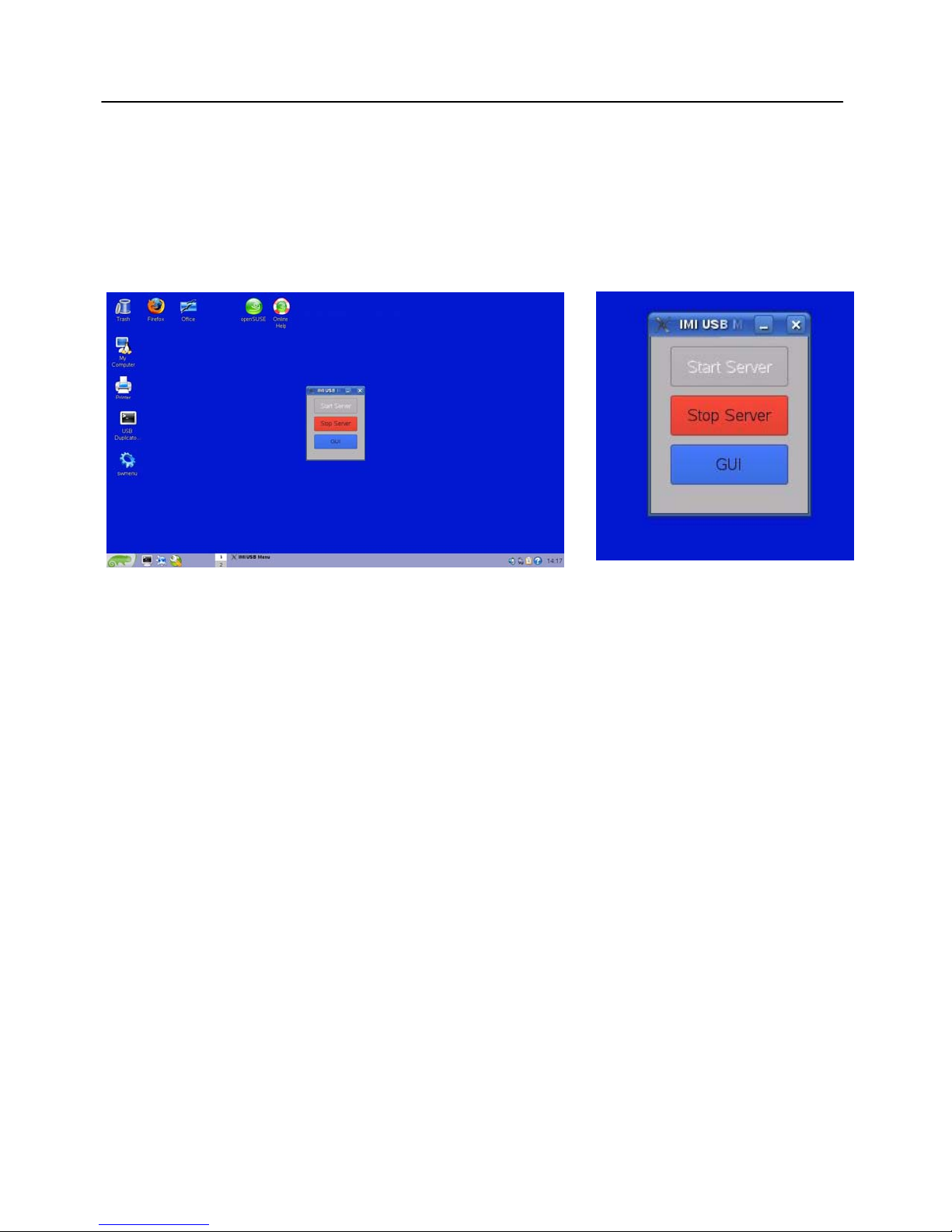
The initial desktop screen on the M6310 is shown below.
Figure 4-1 Initial Desktop M6310 Screen
The M6310 is a fully featured Linux operating system. In addition to standard Linux
programs, there a special programs written and or used by IMI to operate the M6310.
The two main IMI M6310 programs that run on the M6310 are the backend M6310
Server and the front end M6310 GUI. The backend M6310 Server program runs the
IMI USB hardware that operate on the USB devices inserted into on the M6310 front
panel. The M6310 GUI (“Graphical User Interface”), is the standard M6310 program
used to create and edit M6310 Jobs that will perform the desired USB drive tasks.
The Gray and Red buttons on the M6310 Button Menu shown in Figure 4-1 allows
starting and stopping the M6310 Server and starting the M6310 GUI. Note that upon
boot, the M6310 Server is already running. Unless otherwise stated, the following
section will assume there is only one M6310 slice or that the user is running from the
Master M6310 slice and all other M6310’s are running and correctly hooked together
using the M6310-CAB Ethernet switch and KVM (“Keyboard/Video/Mouse” device).
Normally, the display will be shown for a single M6310.
Upon execution of the blue GUI button using a single mouse click, the top menu screen
of the M63W will appear similar to the screen shown in Figure 4-2.
22
 Loading...