

International Harvester Company BD-144 Series, BD-154 Series, BC-144 Series, BC-144A, BC-144 Service Manual
...
n
INTERNATIONAL
BD-144,BD-154Series
DIESEL ENGINES
and
BC-144Series
PETROL ENGINES
SM-12A
INTERNATIONAL HARVESTERCOMPANYof GREAT BRITAIN LIMITED
P.O.BOX25 259 CITY ROAD LONDON ECIP1AD
KBB/4/78 MeC

•
•
•
i
~
.'
SM-11A
SERVICE MANUAL
INTERNATIONAL
GENERAL
MANIFOLDS.
CYliNDER HEAD
AND VALVES
CONNECTING RODS.
PISTONS AND
CYLINDER SLEEVES
LUBRICATION
SYSTEM
BC-144 BD-144
&
BD-154
SERIES ENGINES
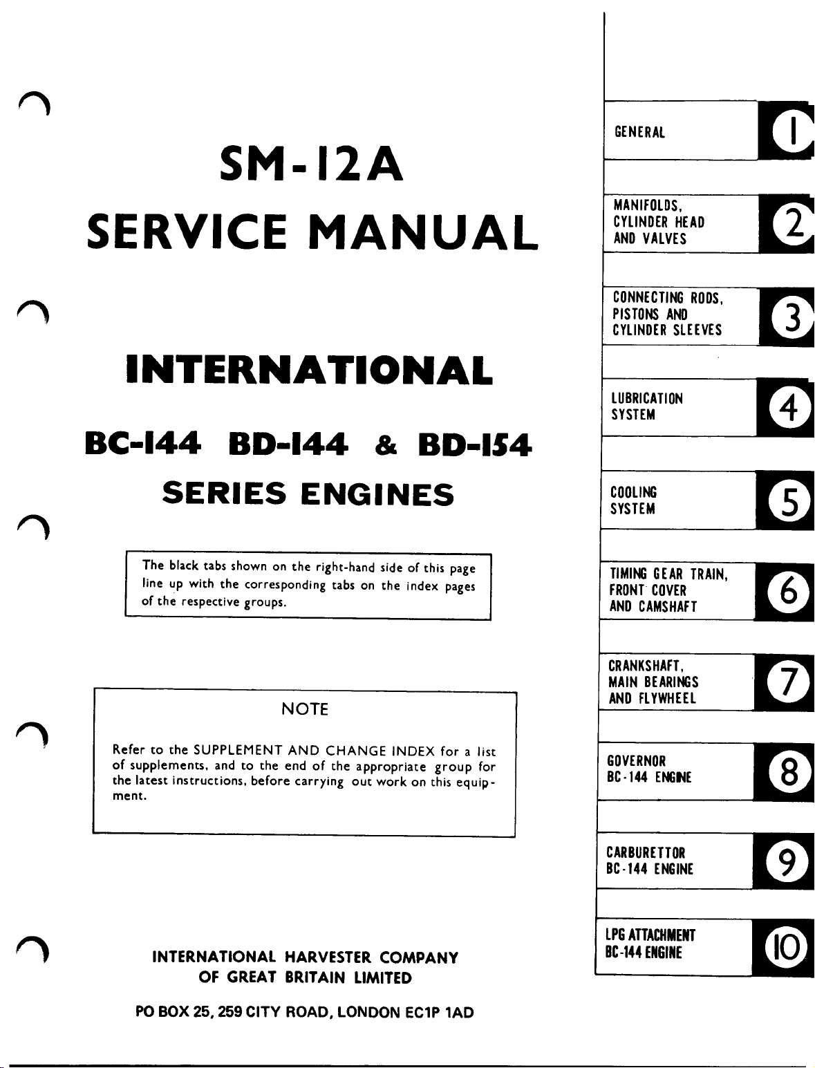
The black tabs shown on the right-hand side of this page
line up with the corresponding tabs on the index pages
of the respective groups.
NOTE
Refer to the SUPPLEMENT AND CHANGE INDEX for a list
of supplements. and to the end of the appropriate group for
the latest instructions. before carrying out work on this equip-
ment.
COOLING
SYSTEM
TIMING GEAR TRAIN.
FRONT COVER
AND CAMSHAFT
CRANKSHAFT •
MAIN BEARINGS
AND FLYWHEEL
GOVERNOR
BC -144 ENGINE
INTERNATIONAL HARVESTERCOMPANY
OF GREAT BRITAIN LIMITED
PO BOX 25, 259 CITY ROAD, LONDON EC1P lAD
CARBURETTOR
Be -144 ENGINE
LPG ATTACHMENT
BC-144 ENGINE

r---------
•
•
•
•
•

INTERNATIONAL
8C-144, 80-144
SERIES ENGINES
&
80-164
GROUP 1
GENERAL
1- 1
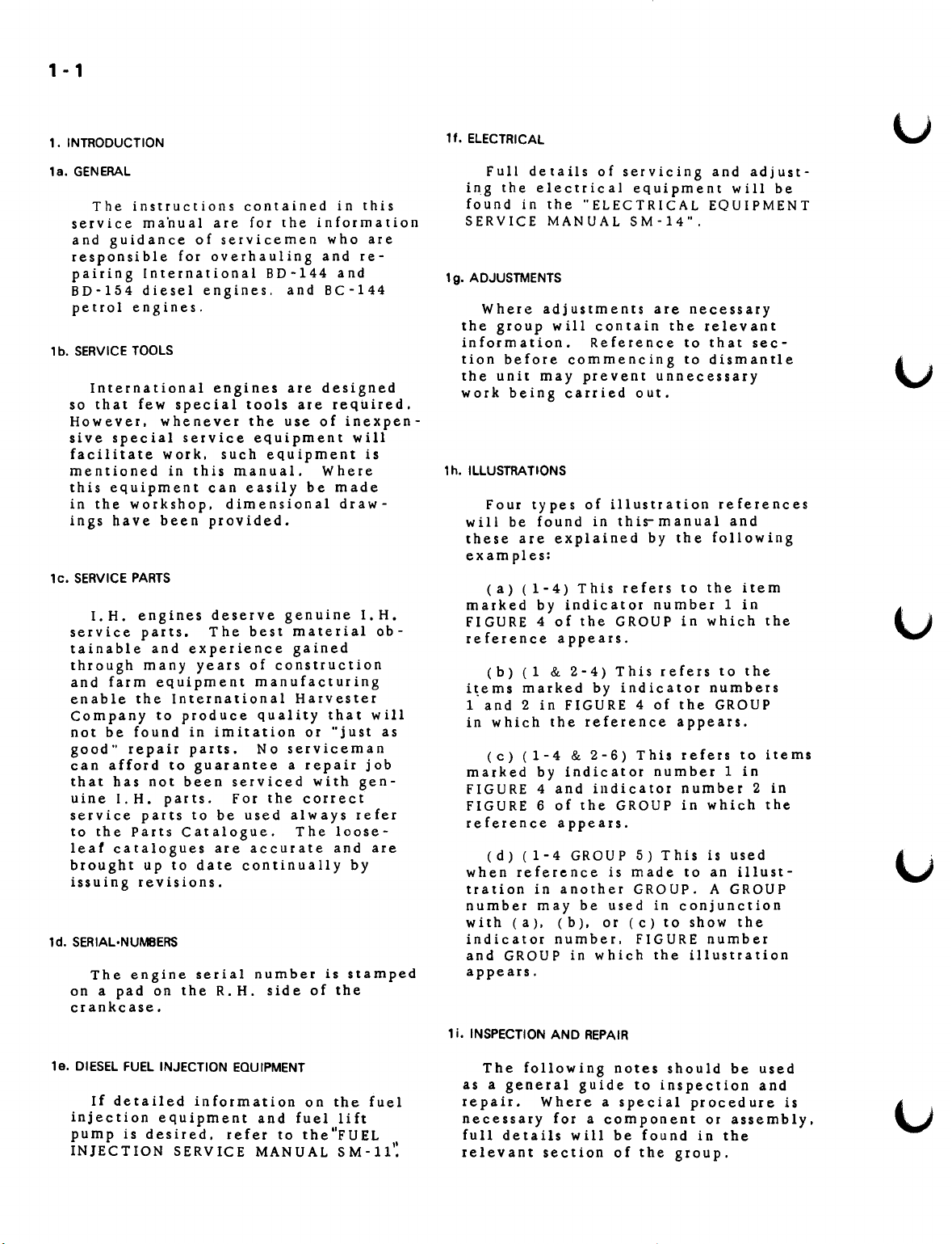
1. INTRODUCTION
1f.
ELECTRICAL
u
1a. GENERAL
The instructions contained in this
service m an u al are for the information
and guidance of servicemen who are
responsible for overhauling and re-
pairing International BD-144 and
BD-154 diesel engines, and BC-144
petrol engines.
, b, SERVICETOOLS
International engines are designed
so that few special tools are required.
However. whenever the use of inexpen-
sive special service equipment will
facilitate work. such equipment is
mentioned in this manual. Where
this equipment can easily be made
in the workshop. dimensional draw-
ings have been provided.
1c. SERVICEPARTS
I.
H. engines deserve genuine
service parts. The best material ob-
tainable and experience gained
through many years of construction
and farm equipment manufacturing
enable the International Harvester
company to produce quality that will
not be found in imitation or "just as
good" repair parts. No serviceman
can afford to guarantee a repair job
that has not been serviced with gen-
uine
I.
H. parts. For the correct
service parts to be used always refer
to the Parts Catalogue. The loose-
leat catalogues are accurate and are
brought up to date continually by
issuing revisions.
td. SERIAL·NUMBERS
The engine serial number is stamped
on a pad on the R. H. side of the
crankcase.
Full details of servlclng and adjust-
ing the electrical equipment will be
found in the "ELECTRICAL EQUIPMENT
SERVICE MANUAL SM-14",
1g.ADJUSTMENTS
Where adjustments are necessary
the group will contain the relevant
information. Reference to that sec-
tion before commencing to dismantle
the unit may prevent unnecessary
work being carried out.
1h. ILLUSTRATIONS
Four types of illustration references
will be found in this-manual and
these are explained by the following
examples:
(a) (1-4) This refers to the item
I.
H.
marked by indicator number 1 in
FIGURE 4 of the GROUP in which the
re ference appears.
(b) (1
items marked by indicator numbers
i
and 2 in FIGURE 4 of the GROUP
in which the reference appears.
(c) (1-4
marked by indicator number 1 in
FIGURE 4 and indicator number 2 in
FIGURE 6 of the GROUP in which the
reference appears.
(d) (1-4 GROUP 5) This is used
when reference is made to an illust-
tration in another GROUP, A GROUP
number may be used in conjunction
with (a). (b). or(c)toshowthe
indicator number. FIGURE number
and GROUP in which the illustration
appears,
1i.INSPECTIONAND REPAIR
&
2-4) This refers to the
&
2-6) This refers to items
1e. DIESELFUEL INJECTION EQUIPMENT
If detailed information on the fuel
injection equipment and fuel
pump is desired. refer to the"FUEL
INJECTION SERVICE MANUAL SM-ll.
lift
The foLlowLng
as a general g uid e to inspection and
repair. Where a special procedure is
necessary for a component or assembly.
II
full details w ill be found in the
relevant section of the group,
notes should be used
2 ·1
(a) BEARINGS
Inspect for evidence of overheat-
ing. cracks. scores. pitting and
general wear. Replace if necessary.
Soak in oil. wrap or cover until ready
for assembly.
(b) PINS AND BUSHES
Inspect for damage. scoring and
pitting. Check with mating parts for
wear.
(c) GASKETS AND SEALS
Always use new gaskets and seals
during assembly. Be extremely care-
ful not to damage the seal or ga-sket
during installation. pack lip type
seals with grease and use sleeves where-
ever a seal has to be passed over
splines or threads.
(d) GEARS AND SPLINES
Check for cracks. pitting. burrs.
broken or missing teeth. Check for
excessive wear with mating parts.
Remove burrs c a re fu l l
interfere with tooth or spline profile.
REPLACE all parts which show damage
or excessive wear.
(e) WELDS
y •
DO NOT
(h) LUBRICATION FITTINGS
Check for damaged or missing
fittings and replace. Check that
grease and oil galleries are clear.
1j. LUBRICATION
When assembling any part. always
coat all wearing surfaces with the
lubricant specified in the operator's
manual. Use sufficient quantities of
lubricant to prevent any danger of
seizin g , scoring or excessive wear
when the assembly is first operated.
FAILURE TO PROVIDE "STARTING
LUBRICATION" MAY RESULT IN
SERIOUS DAMAGE.
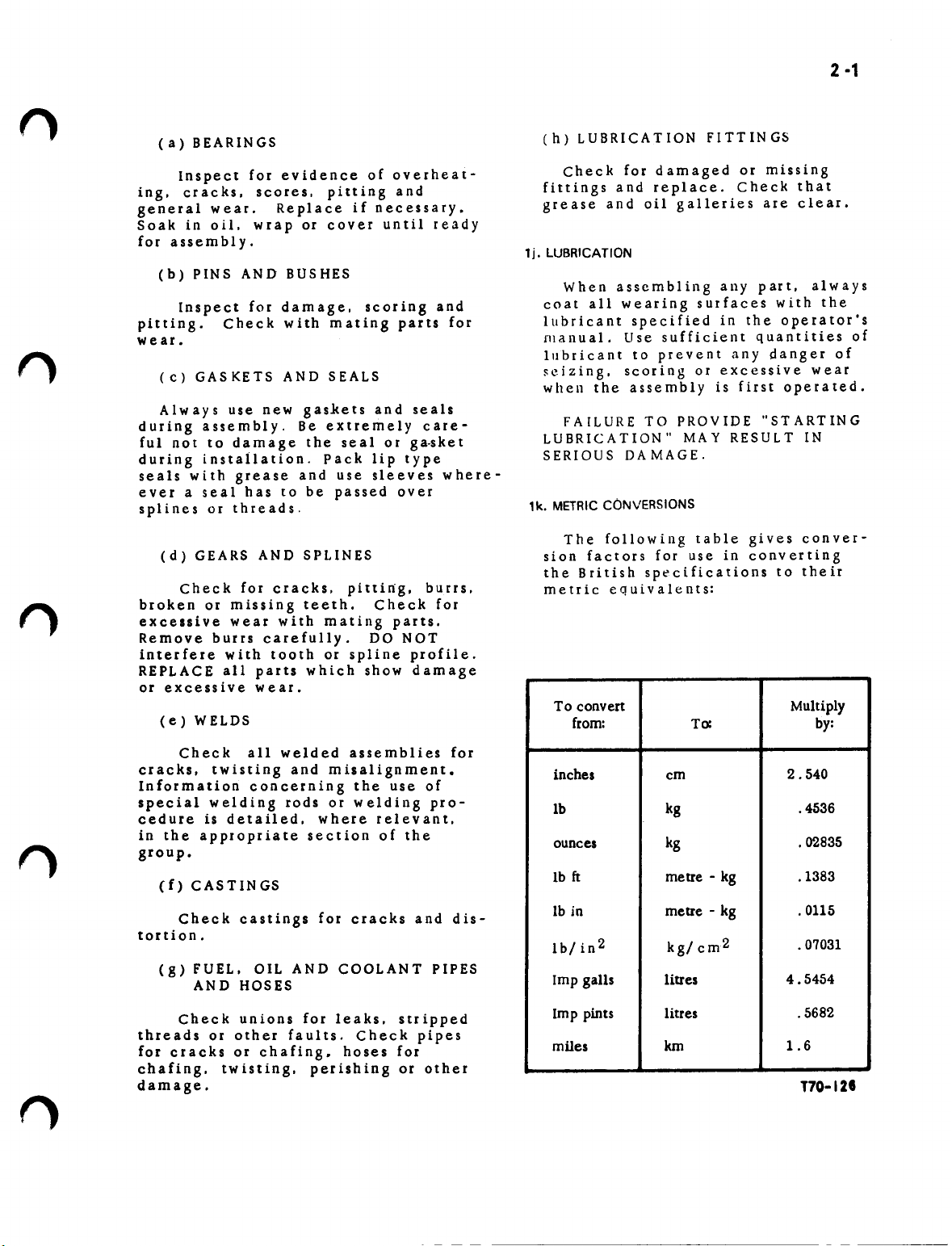
1k. METRICCONVERSIONS
The following table gives conver-
sion factors for use in converting
the British specifications to their
metric equivalents:
To convert Multiply
from:
To:
by:
Check all welded assemblies for
cracks. tWisting and misalignment.
Information concerning the use of
special welding rods or welding pro-
cedure is detailed. where relevant.
in the appropriate section of the
group.
(f)
CASTINGS
Check castings for cracks and dis-
tortion.
(g) FUEL. OIL AND COOLANT PIPES
AND HOSES
Check unions for leaks. stripped
threads or other faults. Check pipes
for cracks or chafing. hoses for
chafing. twisting. perishing or other
damage.
inches
Ib kg
ounces kg
lb
ft
lb in metre - kg
Ib/in2
Imp gaUs litres
Imp pints litres
miles km
cm 2.540
metre - kg
kg/ cm2
.4536
.02835
.1383
.0115
.07031
4.5454
.5682
1.6
T70-12I
3-'
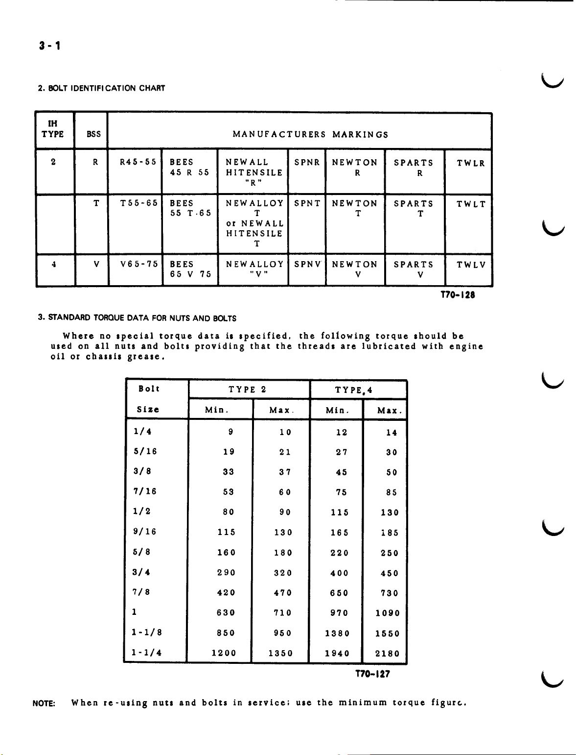
2. BOLT IDENTIFI CATION CHART
IH
TYPE
BSS
MAN UF ACTURERS
MARKIN GS
2 R
R45-55
BEES
45 R 55
NEWALL
HIT ENSILE
SPNR NEWTON
R
SPARTS
R
"R"
T55-65
T
V65-75
4
3. STANDARD TORQUEDATA FORNUTSAND BOLTS
Where no special torque data
used on all nuts and bolts providing that the threads are lubricated with engine
oil or challis grease.
V
Bolt
SIze
1/4
BEES
55 T· 65 T
BEES
65 V 75
NEWALLOY
or NEWALL
HITENSILE
T
NEW ALLOY
"V"
is
specified. the following torque should be
TYPE 2
Min. Max.
9
10
SPNT NEWTON
T
SPNV NEWTON
V
TYPE,4
MIn.
12
SPARTS
T
SPARTS
V
Max.
14
TWLR
TWLT
TWLV
T70-128
NOTE: When re - u s
5/16
3/8
7/16
1/2
9/16
5/8
3/4 290
7/8
1
1-1/8
1-1/4
t
n gnu
ts
and bolt sin se r vic eiulet hem In i mum tor que fig ur (..•
115
160
420
630
850 950
1200
19
33
53
80 90
21 27
37
60 75
130
180
320
470
710
1350
45
115
165
220
400
650 730
970
1380
1940
1090
1550
2180
T70-127
30
50
85
130
185
250
450
4-1
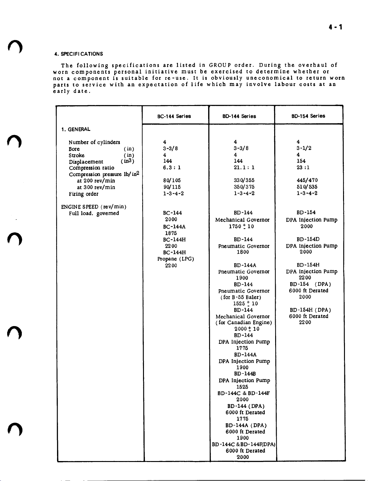
4. SPECIFICATIONS
The following specifications are listed in GROUP order. During the overhaul of
worn components personal initiative must be exercised to determine whether or
not a component is suitable for re-use. It is obviously uneconomical to return worn
parts to service with an expectation of life which may involve labour costs at an
early date.
1. GENERAL
Number of cylinders
Bore
Stroke
Displacement
Compression ratio
Compression pressure lb/ in2
at 200 rev/min
at 300 rev/min
Firing order
ENGINESPEED (rev/min)
Full load. governed
(in)
(in) 4
(in3 )
BC-144 Series BO-144 Series
4
3-3/8
4
3-3/8 3-1/2
4 4
144 144
6.3: 1
80/105
90/115
1-3-4-2
BC-144
2000
BC-144A
21.1: 1
330/355
350/375 510/535
1-3-4-2
BD-144
Mechanical Governor DPA Injection Pump
1750 -: 10
1875
BC-144H
2200
BC-144H
BD-144
Pneumatic Governor
1800
Propane (LPG)
2200
BD-144A
Pneumatic Governor
1900
BD-144
Pneumatic Governor
(for B-55 Baler)
1525 -: 10
BD-144 BD-154H (DPA)
Mechanical Governor
( for Canadian Engine) 2200
2000 ~ 10
BD-144
DPA Injection Pump
1775
BD-144A
DPA Injection Pump
1900
BD-1448
DPA Injection Pump
1525
BD-l44C &BD-l44F
2000
BD-l44 (DPA)
6000 ft Derated
1775
BD-l44A (DPA)
6000 ft Derated
1900
BD-144C &BD-144F(DPA)
6000 ft Derated
2000
BO-154 Series
4
154
23 :1
445/470
1-3-4-2
BD-154
2000
BD-154D
DPA Injection Pump
2000
BD-154H
DPA Injection Pump
2200
BD-154
(DPA)
6000 ft Derated
2000
6000 ft Derated
6 - 1
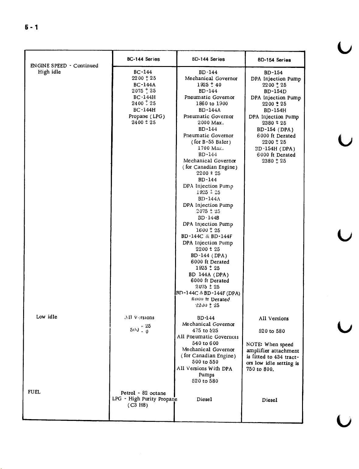
ENGINESPEED - Continued
High idle
BC-144Series
BC-144
2200 -: 25
BC-144A
2075 ~ 25
BC-144H
2400: 25
BC-l44H
Propane (LPG)
2400±25
80-144 Series
BD-144
Mechanical Governor
1925:- 40
BD-144
Pneumatic Governor
1860 to 1900
BD-144A
Pneumatic Governor
2000 Max.
BD-144
Pneumatic Govemor
(for B-55 Baler)
1700 Max.
BD-V14
Mechanical Governor
( for Canadian Engine)
2200t25
BD-144
DPA Injection Pump
19'25 :: 25
BD-1441\
DPA Injection Pump
2075t~5
3D-144B
DPA Injection Pump
1600! 25
BD-144C&.BD-144F
DPA Injection Pump
2200t25
BD-144 (DPA)
6000 ft Derated
1925!25
BD 144A (DPA)
6000 ft Derated
?'U'/5
±
25
flD-144C R>-BD-144F(DPA)
nlH)l1
tr Derate"
-~~VIJ ~
25
80-154 Series
BD-154
DPA Injection Pump
2200:25
BD-154D
DPA Injection Pump
2200!25
BD-154H
DPA Injection Pump
2380t25
BD-154 (DPA)
6000 ft Derated
2200! 25
3D-154H (DPA)
6000 ft Derated
2380 -: 25
Low idle
FUEL
,H1
V,:rSlOns
- 25
5(11) _ 0
Petrol - 82 octane
LPG - High Purity Propane
(C3 H8)
BD-144
Mechanical Governor
475 to 025
All Pneumatic Governors
540t0600
Mechanical Governor
( for Canadian Engine)
500 to 550
All Versions With DPA
Pumps
520 to 580
Diesel
All Versions
520 to 580
NOTE: When speed
amplifier attachment
is fitted to 434 tract-
ors low idle setting is
750 to 800.
Diesel
6 - 1
()
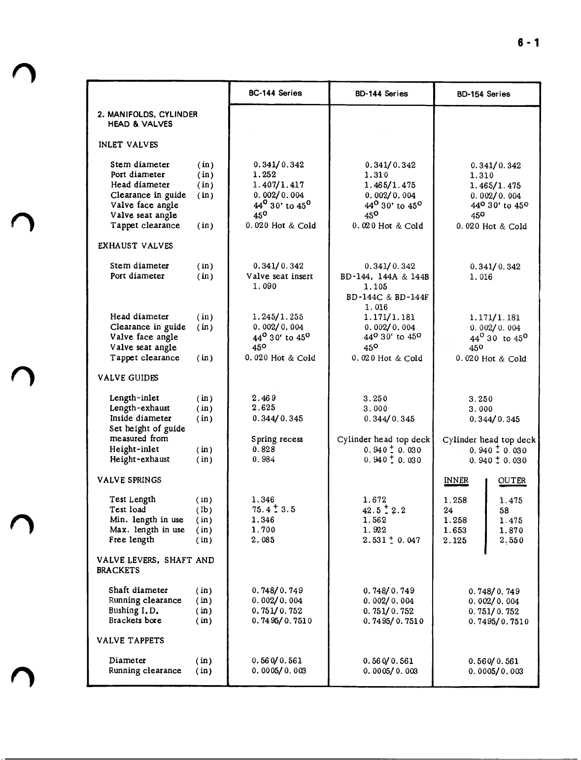
2. MANIFOLDS.CYLINDER
HEAD8tVALVES
INLETVALVES
Stem diameter (in)
Port diameter ( in) 1. 252
Head diameter (in)
Clearanceinguide
Valve face angle
Valve seat angle
Tappet clearance (in)
EXHAUSTVALVES
Stem diameter
Port diameter
Head diameter (in)
Clearance in guide
Valve face angle
Valve seat angle
Tappet clearance
VALVEGUIDES
(in)
(in)
(in)
(in)
(in)
BC-144Series
0.341/O.342
1. 407/1. 417
0.002/0.004
44° 30' to 45°
45° 45°
0.020 Hot&Cold
0.341/O.342
Valve seat insert
1. 090
1. 245/1. 255
O.
002/0.004
44° 30' to 45°
45° 45°
0.020 Hot&Cold
0.020 Hot&Cold
BD-l44. 144A&144B
BD-144C&BD-144F
0.020 Hot&Cold
BD-144Series
0.341/O.342
1.310
1. 465/1. 475
0.002/ 0.004
44° 30' to 45°
0.341/O.342
1.105
1.016
1. 171/1. 181
0.002/0.004
44°30' to 450
BD-154Series
0.341/ 0.342
1.310
1. 465/1. 475
0.002/ 0.004
440 3O'to 450
450
0.020 Hot&Cold
0.341/ 0.342
1.016
1. 171/1. 181
O.
002/O.004
44°30 t045°
450
0.020 Hot&.Cold
Length-inlet
Length-exhaust (in)
Inside diameter (in)
Set height of guide
measured from
Height-inlet
Height-exha ust
VALVESPRINGS
Test Length (in)
Test load
Min. length in use (in)
Max. length in use ( in) 1.700
Free length (in) 2.085
VALVELEVERS,
BRACKETS
Shaft diameter ( in)
Runningclearance
BushingI. D.
Brackets bore
VALVETAPPETS
Diameter
Runningclearance (in)
SHAFTAND
(in)
(in)
(in) 0.984
(lb)
(in)
(in)
(in)
(in)
2.469
2.62.5
0.344/O.345
Spring recess
0.828
1.346
75.4~3.5
1.346
0.748/ 0.749
0.002/ 0.004
0.751/ 0.752
0.7495/ 0.7510
0.560/0.561
O. OOOS/ O.
003
3.250
3.000
0.344/O.345
Cylinder head top deck
O.
940 ~ 0.030
O.
940 ~ 0.030
1.672
42.5 -: ~. 2
1. 562
1. 922
2. 531 ~ 0.047
0.748/ 0.749
0.002/ 0.004
0.751/O.752
0.7495/0.7510
0.560/ 0.561
O. OOOS/ O.
003
3.250
3.000
0.344/O.345
Cylinder head top deck
O.
940 ~ 0.030
O.
940 ~ 0.030
INNER OUTER
-
1.258 1.475
24
1.258
1.653
2.125
0.748/O.749
0.002/ 0.004
0.751/O.752
0.7495/0.7510
0.560/ 0.561
0.0005/0.003
-
58
1.475
1. 870
2,550
7-1
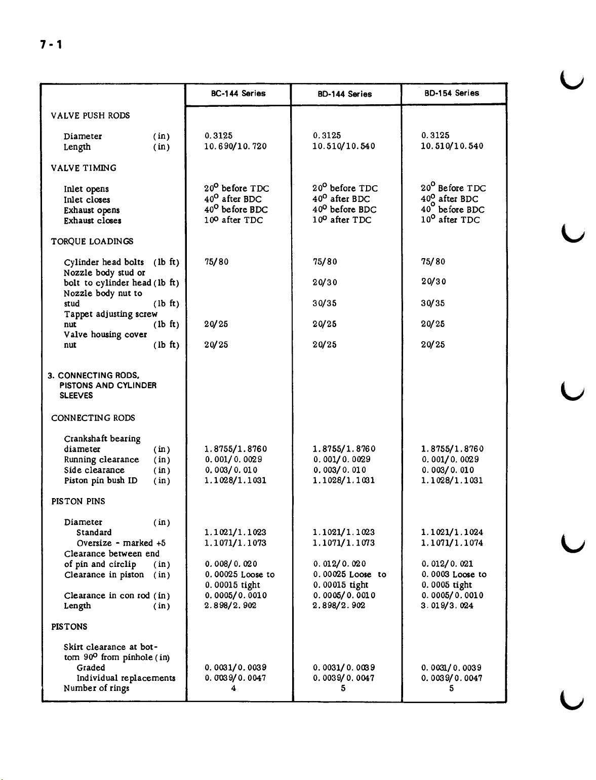
VALVEPUSH RODS
Diameter
Length
VALVETIMING
Inlet opens
Inlet closes
Exhaust opens
Exhaust closes
TORQUE LOADINGS
Cylinder head bolts
Nozzle body stud or
bolt to cylinder head (Ib
Nozzle body nut to
stud
Tappet adjusting screw
nut
Valve housing cover
nut (lb ft)
3. CONNECTINGRODS.
PISTONSAND CYLINDER
SLEEVES
(in)
(in)
(lb ft)
ft)
(lb ft)
(lb ft)
BC-144 Series
0.3125
10.690/10.720
200before TDC
400after BDC
400before BDC
100
after TDC
75/80 75/80
20/25 20/25
20/25
80-144 Series
0.3125 0.3125
10.510/10.540 10.510/10.540
200before TDC
400after BDC
400before BDC
100after TDC
20/30
30/35 30/35
20/25 20/25
80-154 Series
200Before TDC
40~
after BDC
40
before BDC
100after TDC
75/80
20/30
20/25
CONNECTING RODS
Crankshaft bearing
diameter (in)
Running clearance (in)
Side clearance
Piston pin bush ID
PISTON PINS
Diameter
Standard
Oversize - marked
Clearance between end
of pin and circlip (in)
Clearance in piston
Clearance in con rod
Length
PISTONS
Skirt clearance at bot-
tom
900
from pinhole (in)
Graded
Individual replacements
Number of rings
1.8755/1. 8760 1.8755/1. 8760 1.8755/1. 8760
0.001/ O.0029 O.001/O.0029 O.001/O.0029
(in)
(in)
(in)
+5 1.1071/1. 1073
(in)
(in)
(in)
0.003/0.010 0.003/0.010 0.003/0.010
1.1028/1.1031
1.1021/1.1023 1.1021/1.1023 1.1021/1.1024
O.OOS/0.020
O.00025
O.00015
0.0005/0.0010
2.898/2.902
0.0031/0.0039 0.0031/0.0039
0.0"039/0.0047
Loose to
tight
4
1.1028/1.1031
1.1071/1. 1073 1.1071/1.1074
0.012/0.020
0.00025
O.00015
o.
2.898/2.902
0.0039/ 0.0047 0.0039/0.0047
Loose to
tight
OOOS/0.0010 O.0005/0.0010
5
1.1028/1.1031
O.012/O.021
O.0003
O.0005
3.019/3.024
0.0031/0.0039
Loose to
tight
5
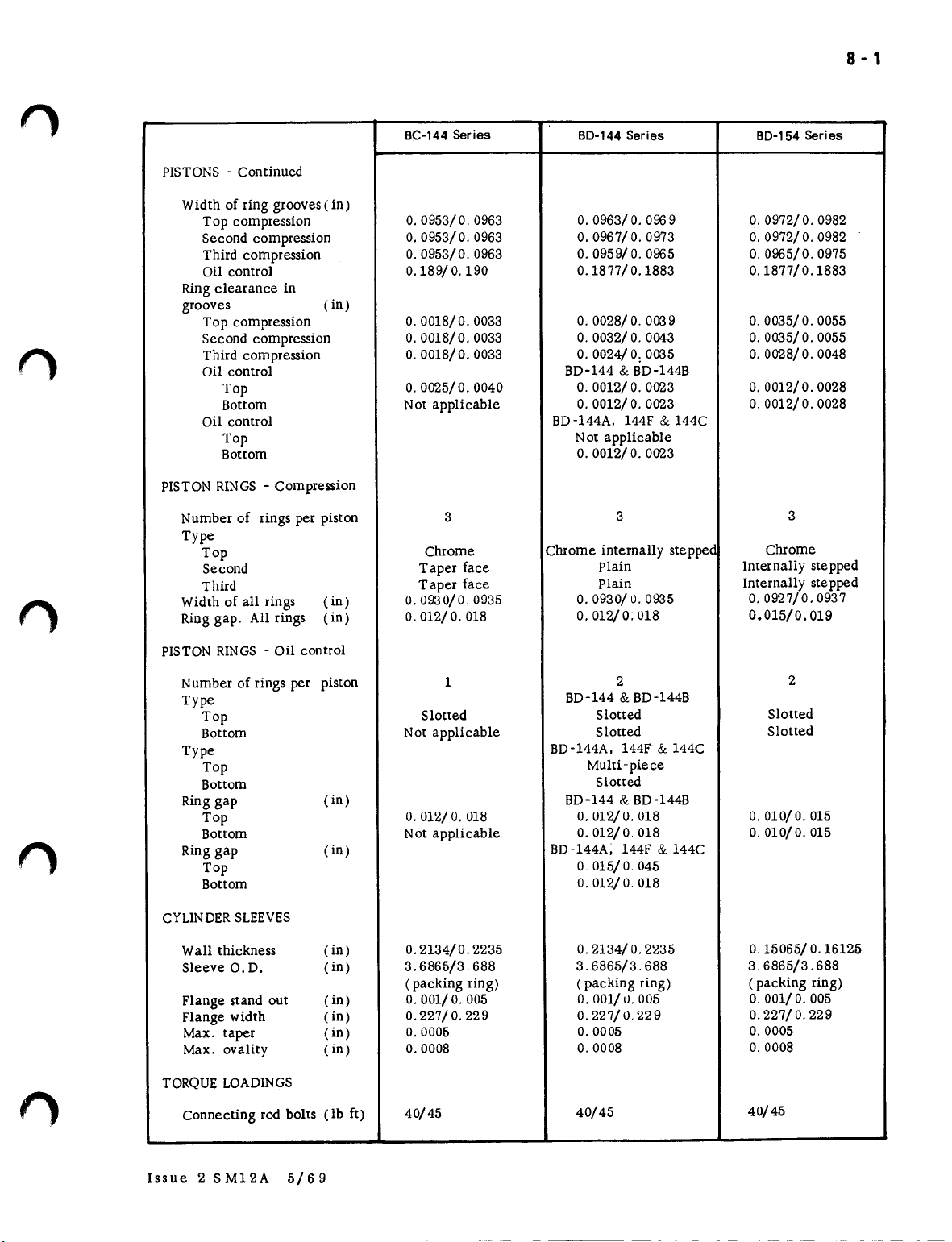
PISTONS- Continued
BC-144
Series
BO-144
Series
BO-154
8 - 1
Series
f)
Width of ring grooves(in)
Top compression
Second compression
Third compression
Oil control
Ringclearance in
grooves
Top compression
Second compression
Third compression
Oil control
Top
Bottom
Oil control
Top
Bottom
PISTONRINGS- Compression
Number of
Type
Top
Second
Third
Width of all rings
Ring gap. All rings
PISTONRINGS- Oil control
rings per piston
(in)
(in)
(in)
0.0953/0.0963
0.0953/0.0963 0.0967/ 0.0973 0.0972/0.0982
0.0953/0.0963
0.189/ 0.190
O.
0018/0. 0033
O.
0018/0. 0033
O.
0018/0.0033
O.
0025/0. 0040
Not applicable
3
Chrome
Taper face
Taper face
0.0930/0.0935
0.012/O.018
O.
0963/O.0969 0.0972/0.0982
0.0959/O.0965 0.0965/0.0975
0.1877/0.1883 0.1877/0.1883
0.0028/0.0039 0.0035/0.0055
O.
0032/O.0043
O.
0024/0: 0035
BD-144&BD-l44B
O.
0012/O.0023
0.0012/ 0.0023 0.0012/0.0028
BD-l44A. 144F
Not applicable
0.0012/O.0023
Chrome internally stepped
Plain
Plain
O.
0930/0. 0935
0.012/0.018
&
144C
3
O.
0.0028/0.0048
0.0012/0.0028
Internally stepped
Internally stepped
0.0927/0.0937
0.015/0.019
0035/0. 0055
3
Chrome
f)
Number of rings per
Type
Top
Bottom
Type
Top
Bottom
Ringgap
Top
Bottom
Ring gap
Top
Bottom
CYLINDERSLEEVES
Wall thickness
Sleeve O. D.
Flange stand out
Flange width
Max. taper
Max. ovality
TORQUELOADINGS
Connecting rod bolts (lb ft)
piston
(in) BD-144&BD-144B
(in)
(in)
(in)
(in) 0.001/O.005
(in)
(in)
(in)
1
Slotted
Not applicable
0.012/O.018
Not applicable
0.2134/0.2235 0.2134/ 0.2235
3.6865/3.688
(packing ring)
0.227/ 0.229
O.
0005
0.0008
40/45
BD-144&BD-l44B
BD-144A. 144F
BD-144A; 144F
2
Slotted
Slotted
Multi-piece
Slotted
0.012/0.018
0.012/0 018
o
015/ 0.045
0.012/ 0.018
3.6865/3.688
(packing ring)
0.001/0.005
0.227/0.229
0.0005
0.0008
40/45
&
144C
&
144C
2
Slotted
Slotted
0.010/0.015
0.010/0.015
0.15065/0.16125
3 6865/3.688
(packing ring)
O.
001/O.005
0.227/ 0.229
0.0005
0.0008
40/45
Issue 2 SM12A 5/69

10· 1
n
n
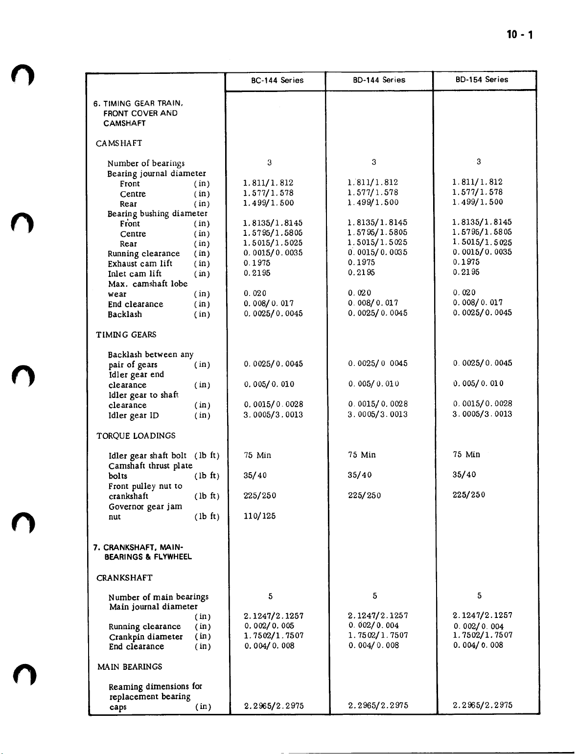
6. TIMINGGEARTRAIN.
FRONTCOVERAND
CAMSHAFT
CAMSHAFT
Number of bearings
Bearing journal diameter
Front
Centre
Rear
Bearing bushing diameter
Front (in)
Centre
Rear
Running clearance
Exhaust cam lift
Inlet cam lift
Max. camshaft lobe
wear
End clearance
Backlash
TlMING GEARS
Backlash between any
pair of gears
Idler gear end
clearance
Idler gear to shaft
clearance
Idler gear lD
(in)
(in)
(in)
(in)
(in)
(in)
(in)
(in)
(in)
(in)
( in)
(in)
(in)
(in)
(in)
BC-144Series
3
1.811/1. 812
1.577/ 1. 578
1.499/1. 500
1.8135/1. 8145
1.5795/1.5805
1.5015/1. 5025
0.0015/0.0035
0.1975
0.2195
0.020
O.008/O.017
0.0025/0.0045
O.0025/0.0045
0.005/ 0.010
O.0015/0. 0028
3. 0005/3. 0013
BO-144Series
3
L811/1. 812
1.577/l.578
1.499/1.500
1. 8135/1. 8145
1.
5795/1. 5805
1.5015/1.5025
0.0015/0.0035
0.1975
0.2195
0.020
O.008/O.017
O.0025/O.0045
0.0025/00045
0.005/0.010
0.0015/ 0.0028
3.0005/3.0013
BO-154Series
3
1.811/1. 812
1.577/1. 578
1.
499/1. 500
1.8135/1.8145
1. 5795/1. 5805
1.
5015/1. 5025
0.0015/0.0035
0.1975
0.2195
0.020
O.008/O.017
0.0025/0.0045
O.0025/0. 0045
0.005/0.010
0.0015/0.0028
3. 0005/3. 0013
n
n
TORQUELOADINGS
Idler gear shaft bolt
Camshaft thrust plate
bolts
Front pulley nut to
crankshaft
Governor gear jam
nut
7. CRANKSHAFT.MAIN-
BEARINGS
CRANKSHAFT
Number of main bearings
Main journal diameter
Running clearance
Crank pin diameter
End clearance
MAIN BEARINGS
Reaming dimensions for
replacement bearing
caps
lit
FLYWHEEL
(lb ft)
(lb ft)
(lb ft)
(lb ft)
(in)
(in)
(in)
(in)
(in)
75
Min
35/40
225/250
110/125
5
2.1247/2.1257
O.002/O.005
1.7502/1.7507
O.004/O.008
2.2965/2.2975
75
75
Min
35/40
225/250
5
2.1247/2.1257
O.002/O.004
1. 7502/1. 7507 1. 7502/1. 7507
0.004/ 0.008
2.2965/2.2975
Min
35/40
225/250
5
2. 1247/2.1257
O.002/O.004
O.004/O.008
2.2965/2.2975
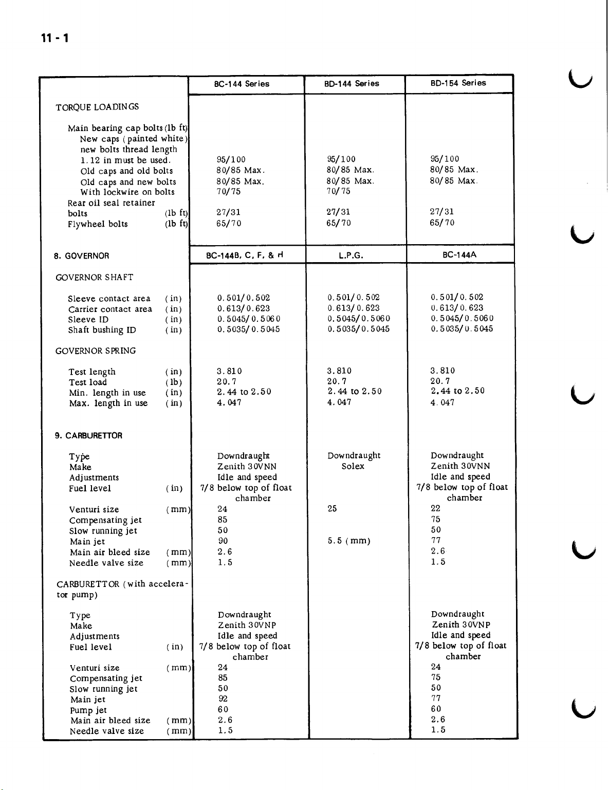
11 - 1
TORQUELOADINGS
Main bearing cap bolts (lb ft)
New caps (painted white)
new bolts thread length
l.12 in must be used.
Old caps and old bolts
Old caps and new bolts
With lockwire on bolts
Rear oil seal retainer
bolts
Flywheel bolts
8. GOVERNOR
GOVERNORSHAFT
Sleeve contact area
Carrier contact area
Sleeve ID
Shaft bushing ID
GOVERNORSPRING
Test length
Test load
Min. length in use
Max. length in use
BC-144 Series
95/100
80/85 Max.
80/85 Max.
70/75
(lb ft)
27/31
(lb ft) 65/70
BC-144B, C, F, &
(in)
0.501/0.502
(in) 0.613/0.623
(in)
(in)
(in)
(lb)
(in)
(in)
0.5045/ 0.506 0
0.5035/ 0.5045
3.810
20.7
2.44 to 2.50
4.047
BO-144 Series
95/100
80/85 Max.
80/85 Max.
BO-154 Series
95/100
80/85 Max.
80/85 Max
70/75
27/31
65/70
rt
L.P.G.
0.501/ 0.502
0.613/O.623
0.5045/0.5060
0.5035/0.5045
3.810
20.7
2.44 to 2.50
4.047
27/31
65/70
BC-144A
0.501/ 0.502
0.613/O.623
0.5045/0.5060
0.5035/ 0.5045
3.810
20.7
2.44 to 2.50
4.047
9. CARBURETTOR
Type
Make
Adjustments
Fuel level
Venturi size
(in) 7/8 below top of float
(rnrn)
compensating jet
Slow running jet
Main jet
Main air bleed size
Needle valve size
(mm) 2.6
(rnm)
CARBURETTOR(with accelera-
tor pump)
Type
Make
Adjustments
Fuel level
Venturi size
(in)
(mm) 24
Compensating jet
Slow running jet
Main jet
pump jet
Main air bleed size
Needle valve size
(rnrn)
(mm)
Downdraught
Zenith 30VNN
Idle and speed
chamber
24 25
85
50
90
1.5
Downdraught
Zenith 30VNP
Idle and speed
7/8 below top of float
chamber
85
50
92
60
2.6
1.5
Downdraught Downdraught
Solex
Zenith 30VNN
Idle and speed
7/8 below top of float
chamber
22
75
50
5.5 (mm)
77
2.6
l.5
Downdraught
Zenith 30VNP
Idle and speed
7/8 below top of float
chamber
24
75
50
77
60
2.6
l.5
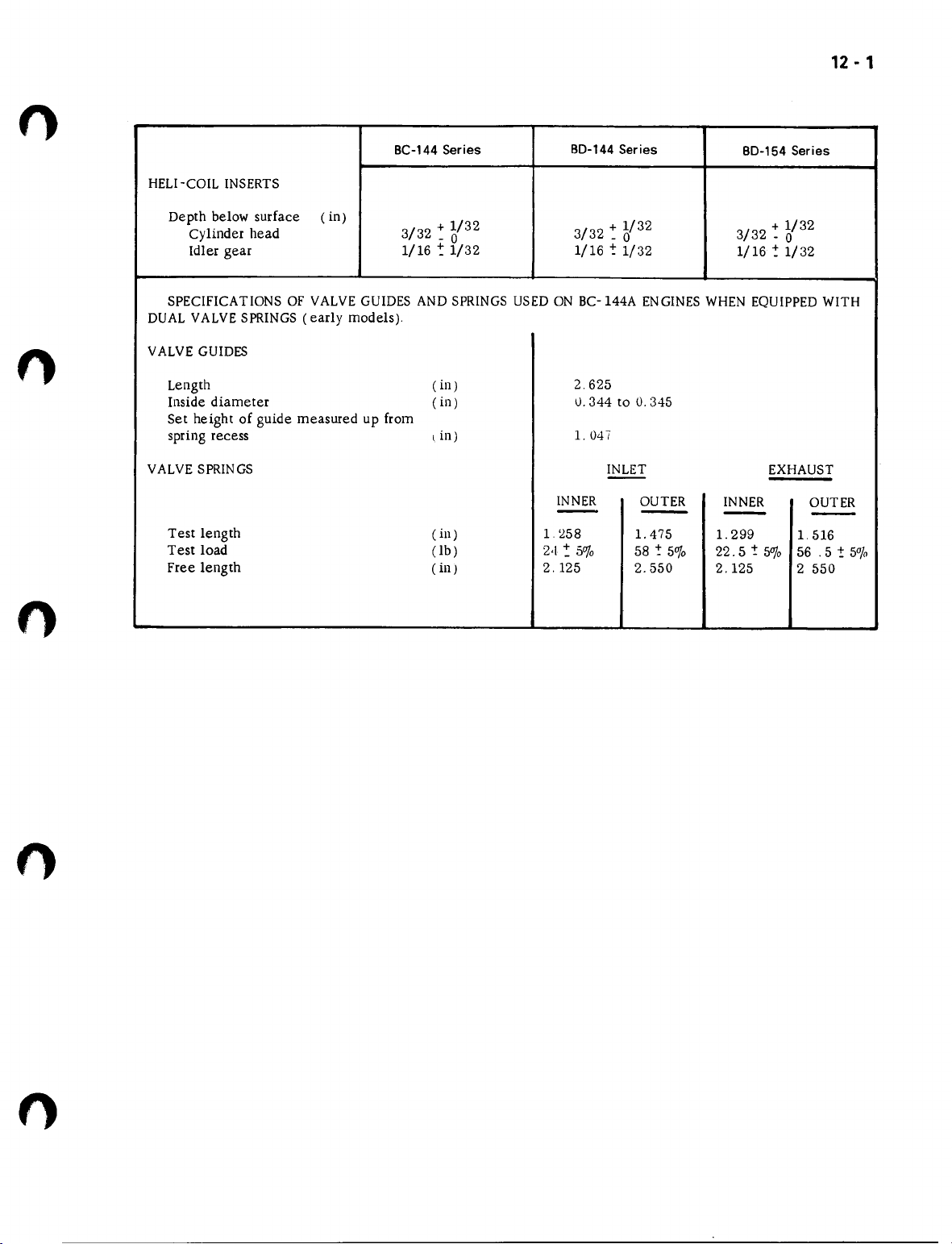
12 - 1
n
BC-144 Series
HELl-COIL INSERTS
Depth below surface
Cylinder head
Idler gear 1/16 ~ 1/32
SPECIFICATlONS OF VALVEGUIDES ANDSPRINGSUSED ON BC-144A ENGINESWHENEQUIPPEDWITH
DUAL VALVESPRINGS(early models).
VALVEGUIDES
Length
Inside diameter ( in) 0.344 to 0.345
Set height of guide measured up from
spring recess
VALVESPRINGS INLET
Test length (ill)
Test load
Free length
( in)
3/32+1/32 3/32+1/32
- 0
(in)
I.
in)
(lb)
(in) 2.125 2.550
BD-144 Series
1/16 -: 1/32
2.625
1.
INNER
--
1.258
2,1~ 50/0
047
- 0
OUTER
-
1.
475
58 -:
5"/0
BD-154 Series
3/32 ~ 5/32
1/16"!1/32
EXHAUST
INNER
-
1.
299
22.5 ! 50/0
2.125
1.
56 .5!
2 550
OUTER
--
516
5
%

•
•
•
•
•

INTERNATIONAL
BC-144, BO-144&BO-164
SERIES ENGINES
GROUP 2
MANIFOLDS, CYLINDER HEAD
AND VALVES

1 - 2
1. DESC~IPTION
1a. MANIFOLDS
separate manifolds are fitted to
the BD-144 and BD-154 series engines.
The inlet manifold on the left hand
side and the exhaust manifold on the
right hand side of the cylinder head.
A one piece casting housing both
the inlet and exhaust manifolds is
fitted on the left hand side of the
BC -144 series engines cylinder head.
The intake manifold also serves as
the mounting for the carburettor.
1b. CYLINDER HEAD AND VALVES
The cylinder head houses the
valves. valve guides. pre-combust-
ion chambers and glow plugs on the
diesel engines. or valves. valve
guides and spark plugs on the petrol
en gine.
The valve lever shaft assembly.
thermostat housing. inlet and ex-
haust manifolds are fitted on the
cylinder head.
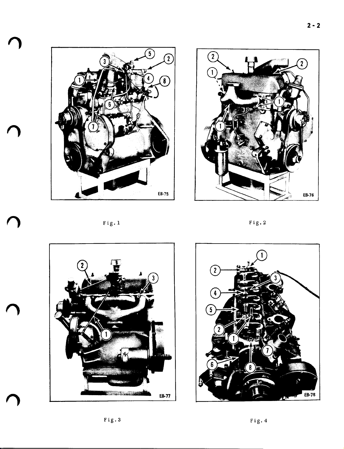
(c) Disconnect the filter to injection
pump fuel pipe (3-1) from the filter.
(d) Disconnect the injection pump
excess outlet pipe (4-1) from the
filter.
(e) Disconnect the injector spill
pipe (5-1) from the filter.
(f) Remove the four bolts (6-1) and
lift
off the manifold.
2. DIESEL ENGINES-EXHAUST
MANIFOLD
(a) Remove the four nuts (1-2) and
withdraw the manifold.
3. PETROL ENGINES-COMBINED
MANIFOLD
(a) Remove the governor to c a r b u r
ettor control rod (1-3).
(b) Disconnect the fuel feed pump
line (2-3) from theca r b u r e
(c) Remove the six bolts (3-3) and
withdraw the manifold.
t
t
or ,
>
The valves are closed by single
valve springs on BD-144 series en-
gines and by dual valve springs on
the BD-154 series engines. Early
models of the BC-144 series engines
were fitted with dual valve springs
but current models have single
valve springs. The exhaust valves
on BC-144 series engines are fitted
with rotators to ensure that all
parts of the valve head are subject-
ed to equal combustion temperatures.
Exhaust valve seat inserts of special-
ly hardened material are fitted to
BC-144 series engines.
2. MANIFOLDS
2a. REMOVAL
1.
DIESEL ENGINES-INLET MANIFOLD
(a) Remove the c r a n k c a s e breather
pipe (I-I).
(b) Disconnect the feed pump to filter
fuel pipe (2 -1) from the filter.
2b. INSTALLATION
Reverse the removal procedure.
3. VALVE LEVERSHAFT ASSEMBLY
3a. REMOVAL
(a) Remove the two nuts (2-2) then
remove the valve housing cover and
gasket.
(b) Remove the nuts (1-4) from the
valve lever shaft brackets (2-4).
(c) Remove the bolt (3-4) from the
centre valve lever shaft bracket
(4-4).
(d) Lift off the valve lever shaft
pressing inward to prevent the as-
sembly dismantling.
u
f)
2-2
Fig.l
Fig.2
Fig.3
Fig.4
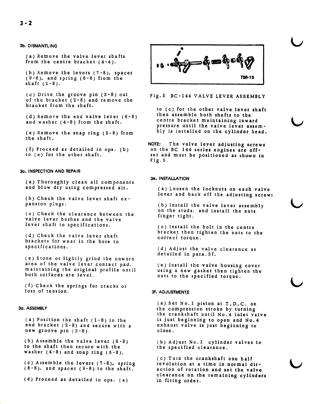
3-2
3b. DISMANTLING
(a) Remove the valve lever shafts
from the centre bracket (4-4).
(b) Remove the levers (7 -8). spacer
(9-8). and spring (8-8) from the
shaft (1-8).
t'
T68-19
(c) Drive the groove pin (3-8) out
of the bracket (2-8) and remove the
bracket from the shaft.
(d) Remove the end valve lever (6-8)
and washer (4-8) from the shaft.
(e) Remove the snap ring (5-8) from
the shaft.
(f) Proceed as detailed in ops. (b)
to (e) for the other shaft.
3<:.
INSPECTIONAND REPAIR
(a) Thoroughly clean all components
and blow dry using compressed air.
(b) Check the valve lever shaft ex-
pansion plugs.
(c) Check the clearance between the
valve lever bushes and the valve
lever shaft to specifications.
(d) Check the valve lever shaft
brackets for wear in the bore to
specifications.
(e) Stone or lightly grind the unworn
area of the valve lever contact pad.
maintaining the original profile until
both surfaces are level.
Fig.5 BC-144 VALVE LEVER ASSEMBLY
to (c) for (he other valve lever shaft
then assemble both sha fts to the
centre bracket m a IntaIntng inward
pressure until the valve lever assem-
bly is installed on the cylinder head.
NOTE:
on the BC 144 series engines are off-
set and m us t be p0sit ion e d ass ho-wn in
Fig.5.
3e. INSTALLATION
The valve lever adjusting screws
(a) Loosen the locknuts on each valve
lever and back off the adjusting scr ews
(b) Install the valve lever assembly
on the studs. and install the nuts
finger tight.
(c) Install the bolt in the centre
br a c ketthen tighten the nuts to the
c orre cttorque.
(d) Adjust the valve clearance as
detailed in para.3f.
(e) Install the valve housing cover
using a new gasket then tighten the
nuts to the specified torque.
(f) Check the springs for cracks or
loss of tension.
3d. ASSEMBLY
(a) Position the shaft (1- 8) in the
end bracket (2-8) and secure with a
new groove pin (3-8).
(b) Assemble the valve lever (6-8)
to the shaft then secure with the
washer (4-8) and snap ring (5-8).
(c) Assemble the levers (7-8). spring
(8-8). and spacer (9-8) to the shaft.
(d) Proceed as detailed in ops. (a)
3f.
ADJUSTMEN1:S
(a) Set No.1 piston at T.D.C. on
the compression stroke by turning
the crankshaft until No.4 inlet valve
is just beginning to open and No.4
exha ust val ve is just beginning to
close.
(b) Adjust No.1 cylinder valves to
the specified clearance.
(C)
Turn the crankshaft one half
revolution at a time in normal dir-
ection of rotation and set the valve
clearance on the remaining cylinders
in firing order.
4-2
4. CYLINDER HEAD
48. REMOVAL
1. DIESEL ENGINES
(a) Remove the manifolds as detailed
in para.2a.
(b) Remove the valve lever assembly
as detailed in para.3a.
(c) Remove the valve push rods (5-4)
and identify them so they can be
installed in their original positions.
(d) Remove the thermostat housing
by-pass hose (6-4).
(e) Remove the three bolts then
remove the thermostat housing (7 -4).
(f) Remove the glow plug earth wire
(7-1) from the front cover.
(g) Disconnect the injector pipes
(8-1) at the injectors.
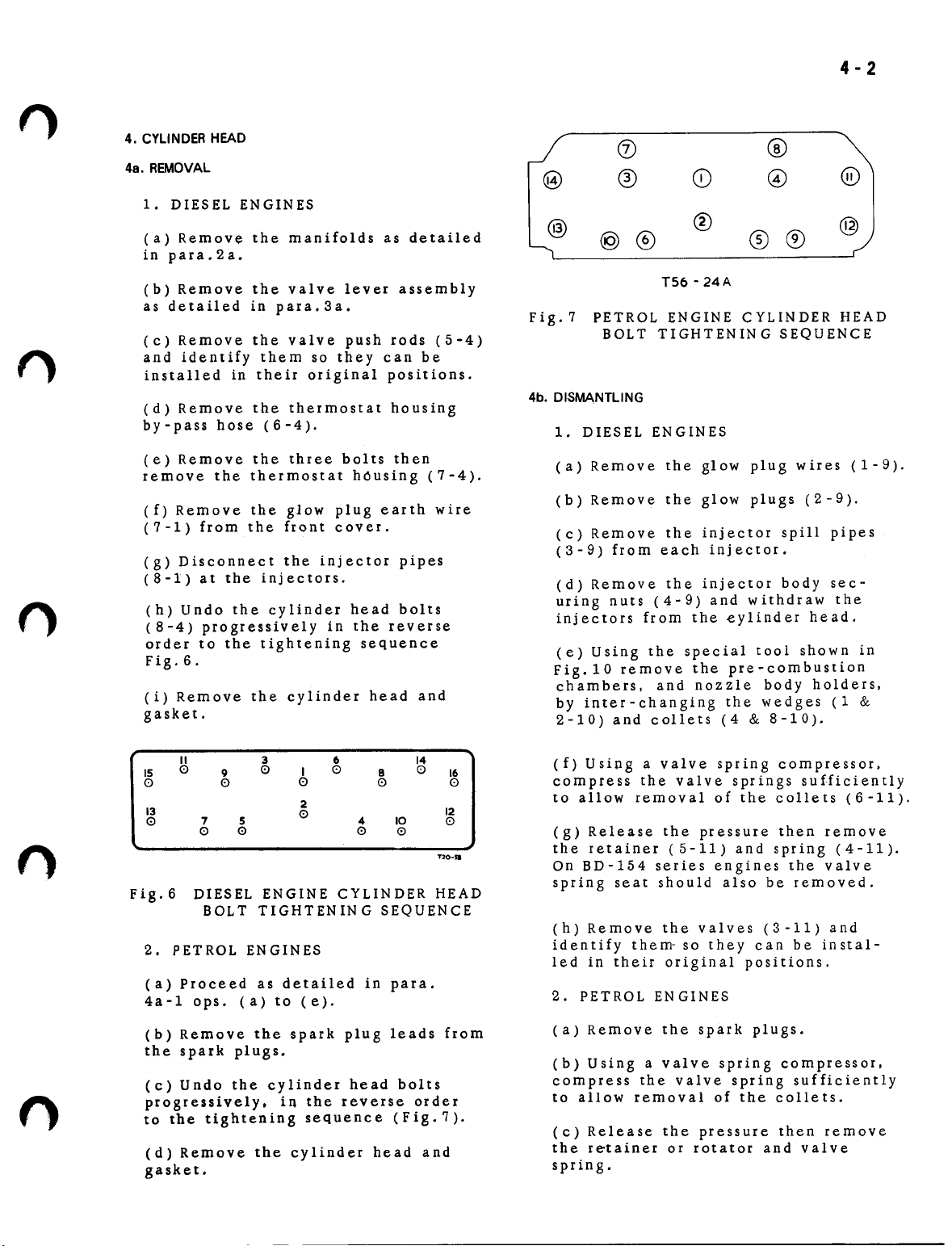
(h) Undo the cylinder head bolts
(8-4) progressively in the reverse
order to the tightening sequence
Fig.6.
(i) Remove the cylinder head and
gasket.
(j)
®
®
@®
TS6-24A
®
@
@
®®
Fig.7 PETROL ENGINE CYLINDER HEAD
BOLT TIGHTENING SEQUENCE
4b.
DISMANTLING
1.
DIESEL ENGINES
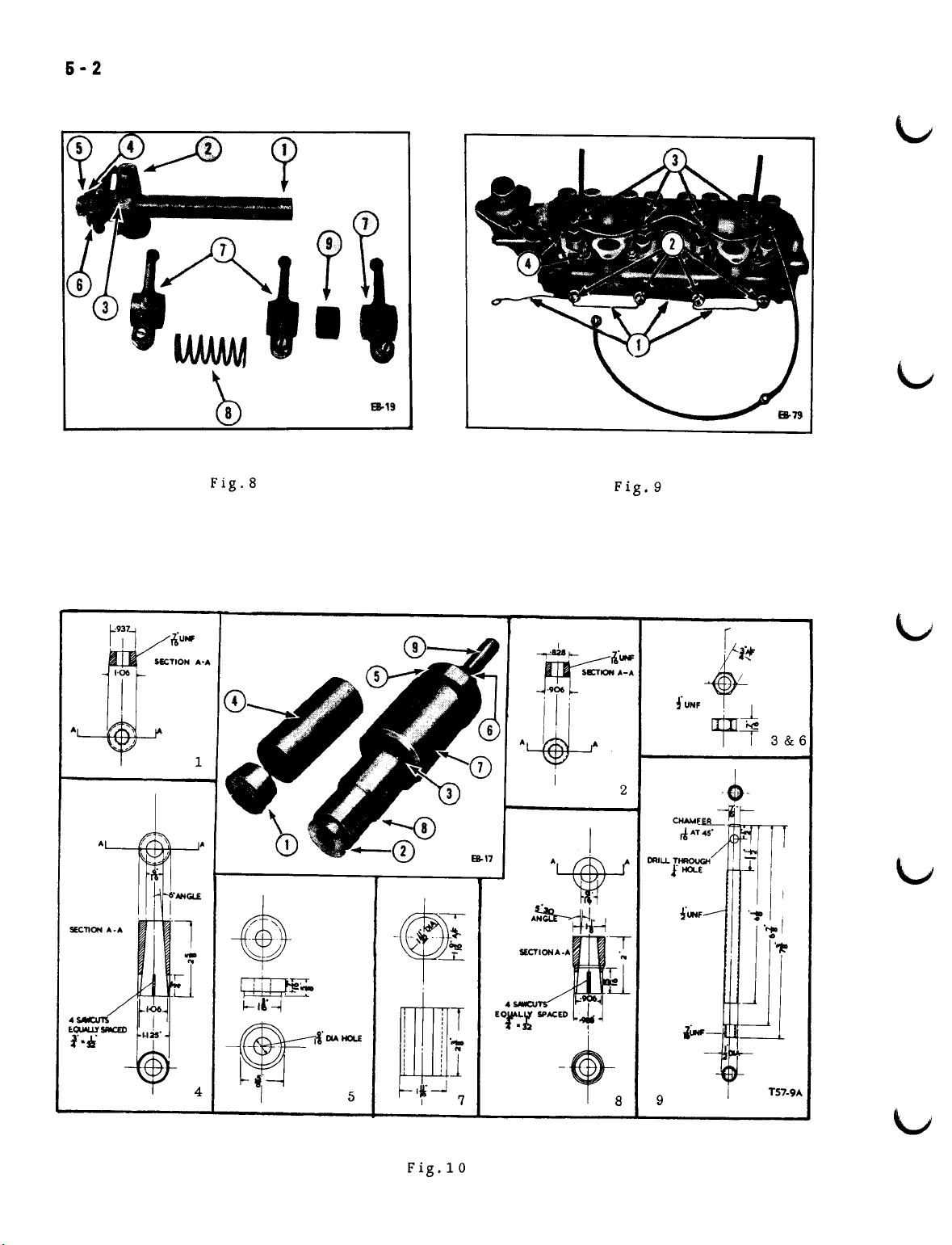
(a) Remove the glow plug wires (1-9).
(b) Remove the glow plugs (2-9).
(c) Remove the injector spill pipes
(3-9) from each injector.
(d) Remove the injector body sec-
uring nuts (4-9) and withdraw the
injectors from the eylind e r head.
(e) Using the special tool shown in
Fig.10 remove the pre-combustion
chambers, and nozzle body holders,
by inter - changing the wedges (1
2-10) and collets (4
&
8-10).
&
II
0
15
0 0
13
0
7
0
3 6
0
9
5
0 0
I
0
2
0
0
8
0 0
4 10
0
14
0
16
12
0
T20-sa
Fig.6 DIESEL ENGINE CYLINDER HEAD
BOLT TIGHTENING SEQUENCE
2. PETROL ENGINES
(a) Proceed as detailed in para.
4a-l ops. (a) to (e).
(b) Remove the spark plug leads from
the spark plugs.
(c) Undo the cylinder head bolts
progressively. in the reverse order
to the tightening sequence (Fig. 7).
(d) Remove the cylinder head and
gasket.
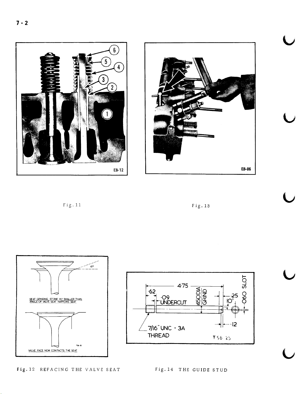
(f) Using a valve spring compressor,
compress the valve springs sufficiently
to allow removal of the collets (6-11).
(g) Release the pressure then remove
the retainer (5-11) and spring (4-11).
On BD-154 series engines the valve
spring seat should also be removed.
(h) Remove the valves (3-11) and
identify them- so they can be instal-
led in their original positions.
2. PETROL ENGINES
(a) Remove the spark plugs.
(b) Using a valve spring compressor.
compress the valve spring sufficiently
to allow removal of the collets.
(c) Release the pressure then remove
the r et ain e r0r rot at0ran d val v e
spring.
6-2
S-19
Fig.8
Fig.9
Fig. 1 0

8-2
f)
f)
(d) Slide the rubber cups. if fitted.
off the inlet valve stems. These can
be discarded.
(e) Remove the valves and identify
them so they can be installed in
their original positions.
4c. INSPECTION AND REPAIR
(a) Thoroughly clean all components
re mo ving all traces of old gasket
material and carbon deposits. espec-
ially from the valve guide bores.
(b) Inspect the cylinder head for
cracks and burnt metal around the
valve ports.
(c) Inspect the valve seats for pitting.
On BC-144 series engines the exhaust
valve seat inserts may be removed
by grinding or chiselling
proves this necessary.
(d) Check the valve guide s for burn-
ing or cracks and against the dimen-
sions given in specifications. Press
out the valve g uid e s (2-11) from the
underside of the cylinder head (1-11)
if inspection proves this necessary.
(e) Check that the valve heads are
not excessively worn or pitted.
(f) Check the valve stems for bends.
wear. excessive pitting. or "mush-
ro oming " of the ends. Check the
collet grooves in the stems to ensure
they have not lost their shoulders.
(g) Check the valve springs for rust,
pitting, or cracks and against the loads
given in specifications.
(h) Check the retainers for rust and
cracks.
if
inspection
(1) If the valve guides were removed
press in new guides to the dimensions
given in specifications. Ream the
valve g uide s to the dimensions given
in specifications.
(m) If the exhaust valve seat inserts
were removed take a fine cut. if
necessary. from the bottom of the
counterbore to ensure a square seat
for the replacement insert.
(n) Thoroughly chill the valve seat
inserts. install them then peen over
the edge of the insert around its
entire circumference. The inserts
should be recessed in the head 0.006"
- 0.014".
(0)
Reface the valve seats to the
correct angle. Seats that are too
wid e afterr e f a c in g sh0u1d ben ar r0wed
by grinding the top edge of the seat
with a stone of a smaller angle,
(150preferred). Refer to Fig.12.
(p) Mount a dial indicator on the
pilot shank and check that seat run-
out does not exceed 0.003".
(q) Reface the valves but reject
valves that grind down to a fine edge.
(r) Using carborundum paste lap in
the valves. Ensure that all carborun-
dum paste is removed from the valves
and valve seats after the lapping
operation.
(s) Check the valves in their seats
using engineers blue. A complete
ring of contact must be shown on
both faces.
(t)
If necessary. grind the ends of
the valve stems removing only suf-
ficient metal to give a square end.
(i) Check the valve rotators for rust
and wear.
(j) Check the operation of the valve
rotators by placing the rotator on a
spring. a ball bearing on top of the
rotator and pl ac e the assembly in a
valve spring tester with the ram bear-
ing on the ball bearing. On applying
pressure to the ram the rotator,
if serviceable. will be seen to move.
(k) Check the outside face and the
ribs inside the collets for wear.
4d. ASSEMBLY
1. DIESEL ENGINES
(a) Coat the valve stems with clean
engine oil and install them in their
original posit ions.
(b) On BD-154 series engines install
the valve spring seats.
(c) Install the valve springs and ret-
ainers.
7·2
Fig.ll
SEAT GRINDINGSTONE 15° SMAU.ERTHAN
ANGLE OF VALVE SEAT NARROWS SEAT
EB-12
·62
f.-
11-'09
., UNDERCLJr
-
-
lJ
7/16" UNC - 3A
THREAD
475
Fig.13
«0
Oz
~a:
"'St~
-
•
·25
--
1
~
___i
-
L
~+
.......
TS6 'LS
·12
•
ES-86
t-
9
t/)
g
VALVE FACEt-DW CONTACTS TI-£ SEAT
Fig.12 REFACING THE VALVE SEAT
Fig.14 THE GUIDE STUD
8-2
..
.
,,,,,
(d) Using a valve spring compressor.
compress the springs and fit the
collets.
(e) Install new pre-combustion
chamber gaskets then insert the pre-
combustion chambers using aligning
tool number IH 3454 Fig. 13.
NOTE:
chamber is entered correctly in the
head. otherwise the glow plug element
may contact the sides of the chamber
and be burnt out.
Ensure that the pre-combustion
(f) Install the second gaskets and
the pre-combustion chamber holders.
(g) Install the injectors and tighten
the nuts to the specified torque.
(h) Install the glow plugs and glow
pl ug in terconnecting wires.
2. PETROL ENGIN ES
(a) Coat the valve stems with clean
engine oil and install them in their
original positions .
(b) Install the valve springs. ret-
ainers and rotators.
(b) Screw two guide studs manufactured
to the dimensions shown in Fig. 14
into the cylinder block to hold the
gasket in place and ensure the
correct alignment of the cylinder
head .'
(c) Install the cylinder head.
(d) Dismantle the valve lever shaft
ass e m b1Y a s d eta il e din p'ar a. 3b'.
op. (a). then install the centre
valve lever shaft bracket on the
cylinder head and insert the long
bolt.
(e) Remove the guide studs then
insert the remaining bolts.
(f) Tighten the bolts progressively
in the order shown in Figs. 6 or 7
to the specified torque.
(g) Remove the long bolt from the
centre valve lever shaft bracket and
remove the bracket.
(h) Install the push rods in their
original positions.
(i) Assemble the valve lever assembly
as detailed in para.3d. op. (d).
..
""fY
(c) Using a valve spring compressor.
compress the springs and fit the
collets.
(d) Install the spark plugs. using
new washers.
4e.
INSTALLATION
(a) Apply a light coating of clean
engine oil to the cylinder head
mating face and install a new gasket.
(j) Install the valve lever assembly
as detailed in para.3e.
(k) Install the thermostat housing.
(1)
Install the thermostat by-pass
hose •
(m) Secure the glow plug earth wire
to the front cover.
(n) Install the manifolds as detailed
in para.2b.

•
•
•
•
•
 Loading...