

International Harvester Company 105 Operator's Manual
Break-in
at
mower
for
10hours
first
INTRODUCTION
The International 105 Balanced Mower
is designed for use on the International Cub 8
Lo-Boye, Farmall Cub e, International and
Farmal18 Super A, Super A-l, 100, 130 and
140 Tractors. It is well suited for both industrial and farm use. A completing package
is required to mount on your tractor.
This mower is especially built for highspeed mowing. It is ruggedly built with an
exclusive new wrist-action drive, balanced
for smooth running for longer machine life
and operator's comfort. It is especially
designed for cutting heavy hay and othervegetation.
or for mowing highway shoulders,
rights-of-way, and other industrial applications. It will operate efficiently with the cutter bar at any angle from. 450 below horizontal
to 900 vertical. This feature makes it desirable for cutting steep highway banks and
slopes. The. free floating action of the cutter
bar permits close operating positions along
the contour of the ground.
The tractors must be equipped with one of
the following units:
Touch Control for Farmall and hlternational
140 Basic Tractors for use with 105 Mowers
(Factory Application) (Standard Equipment on
hlternational 140 Standard Tractor).
354 467 R99 Special Touch Control for
Farmall and mternational"A", Super A,
100, 130, and 140 Tractors not previously
equipped with Touch Control.
The hydraulic system enables the operatorto
raise the cutter bar to clear obstructions
or to raise the mowe r to transport position.
The mower operator can quickly adjust the
cutter bar for height to meet various mowing
conditions, permitting independent control ofthe
inner and outer shoes. A completing pack-
age is required for the International Cub Lo-
Boy and Farmall Cub Tractors.
358 119 R 91 Special Touch Control Con-version
Package for Farmall and International
"A", Super A, 100, 130, and 140 Tractors
equipped with Touch Control.
381 223 R91 Restricted Actuator Package
(Factory Application) for International Cub
Lo-Boy, and Farrnall Cub Tractors.
A 5-foot cutter bar is standard equipment,
381 228 R9l Restricted Actuator Package
(Field Conversion) for International Cub LoBoy and Farmall Cub Tractors.
A variety of special knife assemblies areavailable
for this cutter bar.
Note: The Farmall Cub and International
Cub La-Boy tractors must be equipped withhead
gasket 351 989 R6.
Other special equipment and attachmentsare
as follows:
The tractor Fast-Hitch cannot be used in
conjunction with the mower. However, the
Fast-Hitch helper spring parts are required
when the mower is mounted on the Cub or
Cub Lo-Boy Tractors.
Outer Shoe Grass Deflector -to prevent
the cut material from falling into the un-
cut material.
Knife Rack Attachment -to carry extraknife
assembly in the field.
The mower is mounted on the right side ofthe
tractor main frame between the front and
rear wheels. Power is transmitted from the
rear power take-off on the tractor through a
roller chain to the universal joint drive shaft.
A heavy-duty V -belt drive transmits the power
to the balanced drive. The entire drive is
completely shielded.
Curb Lift Attachment for International Cub
Lo-Boy and Farmall Cub Tractors -will
hold the inner shoe above ground level, up
to lO'l high to enable the cutter bar to be
placed in and position with the working
range of 45 below horizontal to vertical.
half throttle
LUBRICA TION
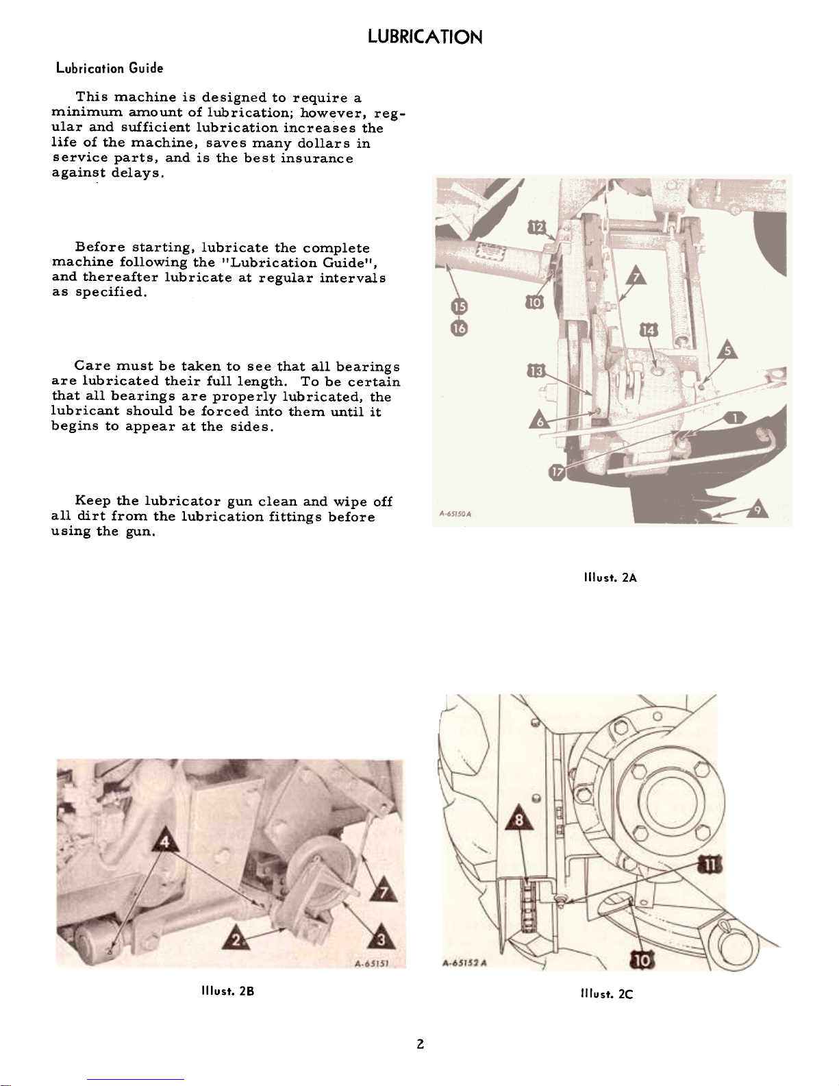
Lubrication Guide
This machine is designed to require a
minimum amount of lubrication; however, regular and sufficient lubrication increases the
life of the machine, saves many dollars in
service parts, and is the best insurance
against delays.
Before starting, lubricate the complete
machine following the "Lubrication Guide",
and thereafter lubricate at regular intervals
as specified.
Care must be taken to see that all bearings
are lubricated their full length. To be certain
that all bearings are properly lubricated, the
lubricant should be forced into them until it
begins to appear at the sides.
Keep the lubricator gun clean and wipe off
all dirt from the lubrication fittings before
using the gun.
Illust. 2A
Illust.28
Illust.2C
2

Key to Lubrication Guide
The symbols shown around the reference numbers in Illusts. 2A, 2B,
and 2C indicate the intervals of lubrication. Paragraph numbers
correspond to reference numbers in the illustrations.
More Often Than Daily
Twice daily, use chassis lubricant (pressure-gun grease)
and apply sufficient lubricant to flush out the old grease and
dirt.
Knife pin
Daily or After Every 10 Hours of Operation
2. Cable pulley support
3. Cable pulley4.
Frame hinge5.
Front hinge
6. Rear hinge
Use chassis lubricant (pressure-gun grease) and apply
sufficient lubricant to flush out the old grease and dirt.
7.
8.
Lifting cable
Drive chain
Use an oilcan.
Lubricate with oil, using an oilcan.
9.
Knife guides, wearing
plates, and knife clips
hllocalities where the soil is sandy or full of grit, theknife
guides, wearing plates, and knife clips should not be
oiled. hl other localities where these conditions do not exist,
oil them daily.
Every Three Days of After 30 Hours of Operati on
10.
Power drive knuckle
Use chassis lubricant (pressure-gun grease) and lubricate
the universal drive center crosses (2 fittings).
Only a few strokes of the pressure-gun are required. Do
not use a high-pressure gun. Excessive lubricant force_d
through the bearings may destroy the seals.
1112.
Rear drive shafthousing
Belt pulley bearing
Use chassis lubricant (pressure-gun grease).
Only a few strokes of the pressure-gun are required. Do
not use a high-pressure gun. Excessive lubricant forced
through the bearings may destroy the seals.
Use a pressure-gun lubricant (Lithium mUlti-purpose
grease, type 2). Apply 3/8-ounce of Lithium mUlti-purpose
grease, type 2. This can be determined in terms of strokes
of the lubricating gun, depending on the type used. Do notuse
a high-pressure gun. Under extremely dusty conditions,lubricate
every 20 hours.
13. Balancing head bearing
housirtg14.
Crankshaft housing
(under top button plug)
Periodic
15.
Knuckle shaft and sleeve16.
Telescoping shields
Two or three times a season, or whenever assembling the
knuckle shaft and sleeve, be sure to insert a liberal amount
of grease in the end of the sleeve; then freely grease the
shaft. Work the shaft in and Qut of the sleeve so that the
sleeve .and shaft are well lubricated. Repeat when necessary.
When assembling the shields, grease and work them in
and out several times. Repeat when ~ecessary.
Two or three times a season, use lithium multi-purpose
grease, type 2 (pressure-gun grease). Ten strokes of the
pressure-gun are required: Do not use a high pressure
gun. Excessive lubricant forced through the bearings may
destroy the seals. .
3
17. Balanced Head
Pivot Bearing (behind
fro~t button plug)
ADJUSTING AND OPERATING
OPERATING
Before going into the field, check to see
that your machine is properly set up, adjusted,
and lubricated as in'structed.
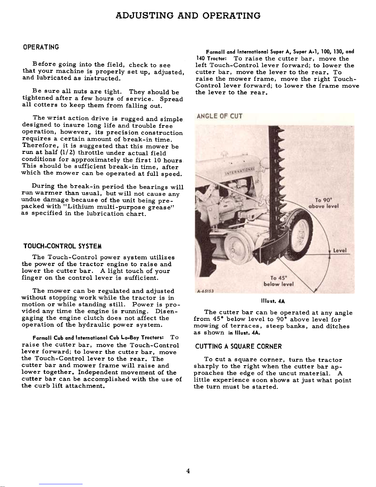
Farmall and Internatianal Super A, Super A.l, 100, 130, and
140 Tractor: To raise the cutter bar. move the
left Touch-Control lever forward; to lower the
cutter bar. move the lever to the rear. To
raise the mower frame. move the right TouchControl lever forward; to lower the frame move
the lever to the rear.
Be sure all nuts are tight. They should be
tightened after a few hours of service. Spread
all cotters to keep them from falling out.
The wrist action drive is rugged and simple
designed to insure long life and trouble free
operation, however, its precision construction
requires a certain amount of break-in time.
Therefore, it is suggested that this mower be
run at. half (1/2) throttle under actual field
conditions for approximately the first 10 hours
This should be sufficient break-in time, after
which the mower can be operated at full speed.
During the break-in period the bearings will
run warmer than usual, but will not cause any
undue damage because of the unit being prepacked with "Lithium multi-purpose grease'!
as specified in the lubrication chart.
TOUCH.CONTROL SYSTEM
The Touch-Control power system utilizes
the power of the tractor engine to raise and
lower the cutter bar. A light touch of your
finger on the control lever is sufficient.
Illust. 4A
The cutter bar can be operated at any angle
from 450 below level to 900 above level for
mowing of terraces. steep banks. and ditches
as shown in Illust. 4A.
The mower can be regulated and adjusted
without stopping work while the tractor is in
motion or while standing still. Power is provided any time the engine is running. Disengaging the engine clutch does not affect the
operation of the hydraulic power system.
Farmall Cub and Internatianal Cub Lo.8oy Tractors: To
raise the cutter bar, move the Touch-Control
lever forward; to lower the cutter bar, move
the Touch-Control lever to the rear. The
cutter bar and mower frame will raise and
lower together. Independent movement of the
cutter bar can be accomplished with the use of
the curb lift attachment.
CUTTING A SQUARE CORNER
To cut a square corner, turn the tractor
sharply to the right when the cutter bar approaches the edge of the uncut material. A
little experience soon shows at just what point
the turn must be started.
4
CUTTER BAR LIFT
The cutter bar lift cable and lifting chain
should be set so that when the Touch-Control
lever is in the forward position, the cutter bar
will be approximately vertical. If the bar is
not vertical, this can be corrected by adjusting
the length of the cable and chain, either
lengthening or shortening.
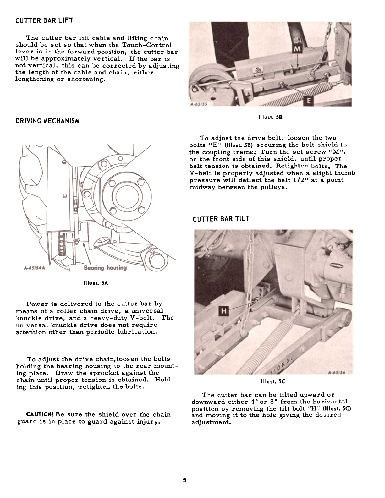
Illust. 58
DRIVING MECHANISM
To adjust the drive belt, loosen the two
bolts 'IE" (1IIust.58) securing the belt shield to
the coupling frame. Turn the set screw "M",
onthe front side of this shield, until proper
belt tension is obtained. Retighten bolts. The
V -belt is properly adjusted when a slight thumb
pressure will deflect the belt 1 (2" a.t a point
midway between the pulleys.
CUTTER BAR TILT
Illust. SA
Power is delivered to the cutter. bar by
means of a roller chain drive, a universal
knuckle drive, and a heavy-duty V-belt. The
univ~rsal knuckle drive does not require
attention other than periodic lubrication.
To adjust the drive chain,loosen the bolts
holding the bearing housing to the rear mounting plate. Draw the sprocket against the
chain until proper tension is obtained. Holding this pos ition, retighten the bolts.
Illust. SC
The cutter bar can be tilted upward or
downward either 40 or 80 from the horizontal
position by removing the tilt bolt "H" (1IIust.5C)
and moving it to the hole giving the desired
adju stme nt.
CAUTION! Be sure the shield over the chain
guard is in place to guard against injury.
5
INNER SHOE BALANCE SPRING
Illust.6A
The pressure of the balance spring is pro-
perly adjusted when 80 to 100 Ibs. is required
to lift the inner shoe.
To adjust the pressure of the balance spring,
loosen the two nuts on the spring adjusting bolt,
turning them clockwise. To apply additional
spring pressure, screw the spring adjusting
bolt into the spring plug, turning the bolt clockwise. To reduce the spring pressure, screw
the adjusting bolt counterclockwise. Tightenthe
hex-nuts against the spring plug.
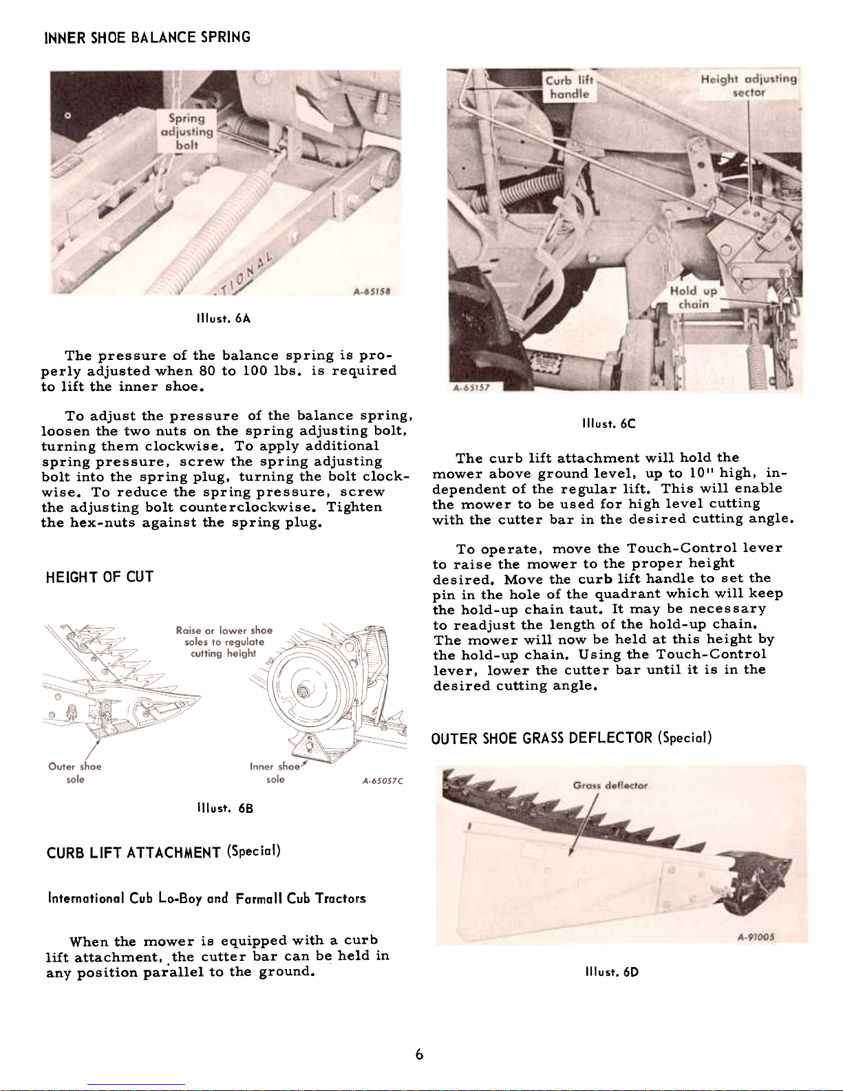
Illust.6C
The cur b lift attachment will hold the
mower above ground level. up to 10" high, independent of the regular lift. This will enable
the mower to be used for high level cutting
with the cutter bar in the desired cutting angle.
HEIGHT OF CUT
To operate, move the Touch-Control lever
to raise the mower to the proper height
desired. Move the curb lift handle to set the
pin in the hole of the quadrant which will keep
the hold-up chain taut. It may be necessary
to readjust the length of the hold-up chain.
The mower will now be held at this height by
the hold-up chain. Using the Touch-Control
lever, lower the cutter bar until it is in the
desired cutting angle.
OUTER SHOE GRASS DEFLECTOR (Special)
Illust. 68
CURB LIFT ATTACHMENT (Special)
International Cub Lo-Boy and Farmall Cub Tractors
When the mower is equipped with a curb
lift attachment. the cutter bar can be held in
any position parallel to the ground. Illust.6D
6
 Loading...