

International Harvester Company 102, 122, 71, 123, Cub Cadet 102 Operator's Manual
...
!
E
U
71,1
22 ant
TRACT0
ATi
,CADET
#
123
L
iNTEFINATIONA,L
E AT
!
®

A in u_r _:_
pmr®d _m _,!eLmi Lo !e p y,_u betl;em urcimrm_amd
_he e@rr.@_ care a_:,::f ef icfes_ opera[ o of yeur
Yok:_r Iota] ! _te Ha_;w)_:R_t dealer
_, Tr_)_ EOr }s4S
:o_ain afmin_ k_st.r_._cdon r_ ui ud, i[: is
r;_a.f:ni:_:_i_;;_U_: the _a< 8, r Disve£;ard tkH:-
_'}pAi't:}_ k:r{! nLH73-
:)_£_ c_d ,.9_'_c c r r <:{s [H:)tHi w:t} [[ _ p a _ze _ 0 m wts [c h
£o£FT a_d :[%];G_IT nd cai:<_ tke 1e£[ a_d right
driver' 5e_I:, Refere_ce t:o NkON'F indR:_,_s
<h_:: £_Nle e:_;d of the. actor[ le REAR, the
8rawbar <w_d

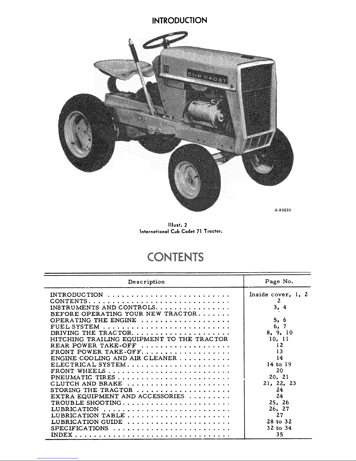
INTRODUCTION
Illust. 1
International Cub Cadet 122 Tractor.
Illust. 1A
International Cub Cadet 102 Tractor.
INTRODUCTION
Illust. 2
{nternational Cub Cadet 71 Tractor.
De scription Page No.
INTRODUC TION ..........................
CONTENTS ...............................
INSTRUMENTS AND CONTROJ._ ................
BEFORE OPERATING YOUR NEW TRACTOR .......
OPERATING THE ENGINE ...................
FUEL SYSTEM ...........................
DRIVING THE TRACTOR .....................
HITCHING TRAILING EQUIPMENT TO THE TRACTOR
REAR POWER TAKE-OFF ...................
FRONT POWER TAKE-OFF ...................
ENGINE COOLING AND AIR CLEANER ...........
ELEC TRICAL SYSTEM ......................
FRONT WHEELS ..........................
PNEU 1ViATIC TIRES ........................
CLUTCH AND BRAKE ......................
STORING THE TRACTOR ....................
EXTRA EQUIPMENT AND ACCESSORIES .........
TROUBLE SHOOTING .......................
LUBRIC ATION ...........................
LUBRICATION TABLE ......................
LUBRICATION GUIDE ......................
SPECIFICA TIONS .........................
INDEX .................................
Inside cover, 1, Z
Z
3, 4
5, 6
6, 7
8, 9, I0
I0, II
IZ
13
14
14 to 19
ZO
ZO, Zl
21, 22, 23
24
24
25, 26
Z6, 27
27
28 to 32
32 to 34
35
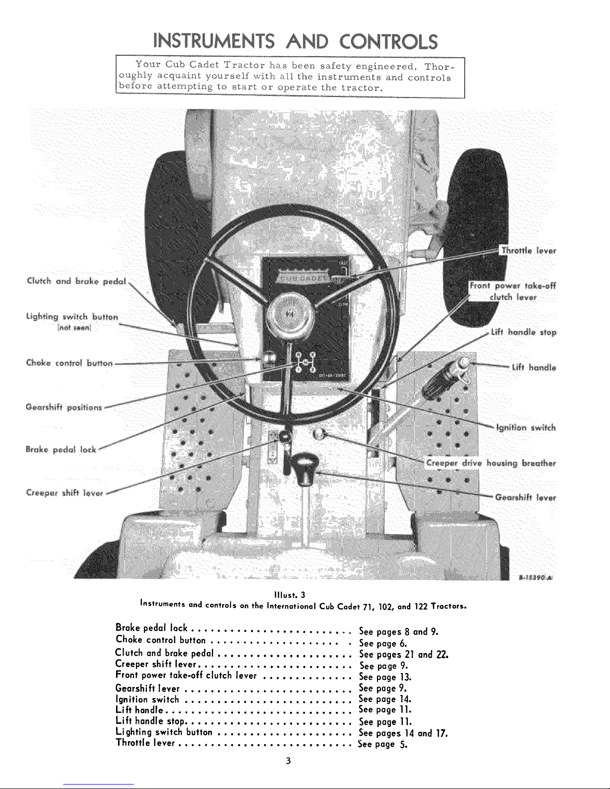
Your Cub Cadet Tractor has been safety engi_'_eered, Thor-
oughly acquaint yourself with a,ll the i_strurr_ents and controls
befoxoe attempting to start oz.- operate the tractor,
Illust. 3
Instruments and controls on the International Cub Cadet 71,
Brake pedal lock ......................... See
Choke control button ..................... See
Clutch and brake pedal ..................... See
Creeper shift lever ........................ See
Front power take-off clutch lever .............. See
Gearshift lever .......................... See
Ignition switch .......................... See
Lift handle ............................. See
Lift handle stop.......................... See
Lighting switch button ..................... See
Throttle lever ........................... See
102, and 122 Tractors.
pages 8 and 9.
page 6.
pages 21 and 22.
page 9.
page 13.
page 9.
page 14.
page 11.
page 11.
pages 14 and 17.
page 5.
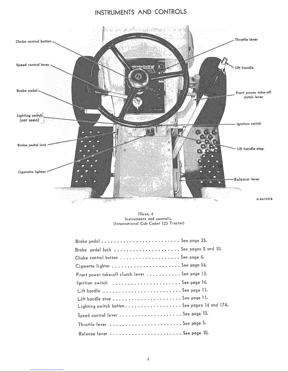
iNSTRUMENTS AND CONTROLS

BEFOREOPERATING YOUR NEW TRACTOR
Lubrication ...... Lubricate the entire tractor. See pages 26 to 32.
Tires .......... Check the air pressure. See pages 20 and 21.
Fuel system ..... Fill the fuel tank with gasoline. See page 6.
Illust. 5
Fuel system and controls on International Cub Cadet 123 Tractor.
(international Cub Cadet 71, 102 and 122 Tractors are similar.)
THROTTLE LEVER
This lever controls the speed of the engine.
When set in a given position, it will maintain
a uniform engine speed.
LIFTING THE HOOD
The tractor hood is arranged to swing up
and forward to make the engine and fuel tank
readily accessible.
GOVERNOR
The governor is set at the time the engine
is assembled and should not require readjust-
ment unless the governor arm is removed or
loosened from the governor shaft. Consult
your International Harvester dealer if the
governor does not function properly.
To raise the hood, take hold of each side of
the hood at the rear, pull outward, and raise
it upward and forward to its stop.
STARTING THE ENGINE
OPERATING
Be sure the fuel shut-off valve is open.
Z. Pull the choke control button all the way
out {see Illust.3 or4). More or less choking may be
necessary due to variations in temperature,
grade of fuel, etc. Little or none will be
needed when the engine is warm.
3. Place the throttle lever halfway between
"SLOW" and "FAST". See Illust.3 or 4.
4.Electric Starting: The engine cannot be
started unless the brake pedal is pressed all
the way down to activate the safety starting
switch.
International Cub Cadet 71, I02, and Igg
Tractors: Check to see that the gearshift lever
is in the neutral position. S,e illust.3.
International Cub Cadet 123 Tractor: Check
to see that the speed control lever is in the
"N" position. See Illust. 4.
All Models: Turn the ignition key clock-
wise to the "START" position and release it
as soon as the engine starts; however do not
operate the motor-generator for more than
30 seconds at any one time. If the engine does
not start within this time, turn the key "OFF"
and wait a few minutes, then try again.
5. After the engine starts, slowly release
the brake pedal and gradually push the choke
THE ENGINE
control button all the way in. Do not use the
choke to enrich the fuel mixture, except when
necessary to start the engine.
Manual Starting: (Tractors without electric
starting). Raise the tractor hood. The retract-
able starter is mounted on a support plate at
the front of the engine at the right side of the
tractor.
l°ut the gearshift lever in the neutral posi-
tion and lock the brake. Turn the key ignition
switch clockwise.
Give a quick steady pull on the retractable
starter handle to start the engine. Do not jerk,
or pull it out to its very end in a rough manner.
A steady pull will accomplish just as much.
Always pull the handle so the cord is in a
straight line through the guide. Maintain your
hold on the handle and allow the cord to return
slowly. Releasing the handle when the cable is
extended will shorten the life of the starter.
5. After the engine starts, slowly release
the clutch pedal and gradually push the choke
control button all the way in. Do not use the
choke to enrich the fuel mixture, except when
necessary to start the engine.
STOPPINGTHE ENGINE
Move the throttle lever to the "SLOW" po-
sition and allow the engine to idle for a short
time before stopping. Then turn the key to the
"OFF" position.
FUEL SYSTEM
Fill the fuel tank with clean, fresh, regular
grade gasoline, preferably at the end of each
day's use. This will force out any moisture-
laden air and prevent condensation in the fuel
tank. Do not mix oil with the gasoline.
The fuel tank filler cap has an air vent.
Keep the vent open at all times to assure
proper flow of the fuel.
Caution! Never remove the fuel tank cap
or fill the fuel tank when the engine is running,
is hot, or when near an open flame. Do not
smoke when working around inflammable fuel,
as the air around the tractor is mixed with a
highly explosive vapor. When pouring fuel,
keep the container or hose nozzle in contact
with the metal of the fuel tank to avoid the
possibility of an electric spark igniting the
gas. Do not spill gasoline on a hot engine.
FUEL SHUT.OFF VALVE
Be sure the shut-off valve on the fuel
strainer under the gasoline tank is open.
Screw out the needle stem (Shut-off valve) un-
til the seat on the stem is tight against the
stop, to prevent leakage or seepage when the
valve is in its full-open position.
CLEANING THE FUEL STRAINER AND SEDIMENT BOWL
After every Z5 hours of operation, clean
he fuel strainer as follows:
i. Close the shut-off valve. See lllusts.7and 7A).
Loosen the knurled nut under the sediment
bowl and remove the bowl and screen.
Z. Clean the sediment bowl and screen.
3. When reassembling, be sure the gasket
between the bowl and the main body is in good
condition and does not leak. Use a new gasket
if necessary.
FUEL SYSTEM
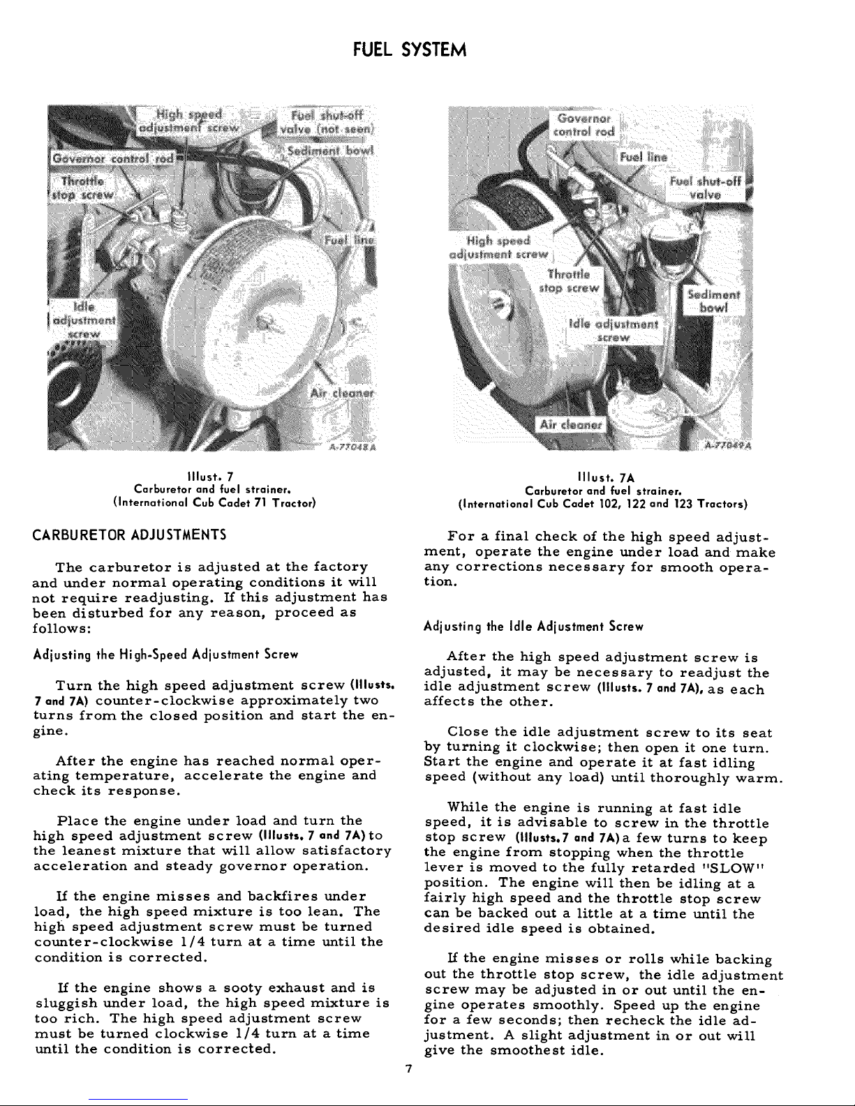
Illust. 7
Carburetor and fuel strainer.
(International Cub Cadet 71 Tractor)
CARBURETOR ADJUSTMENTS
The carburetor is adjusted at the factory
and under normal operating conditions it will
not require readjusting. If this adjustment has
been disturbed for any reason, proceed as
follows:
Adjusting the High-Speed Adjustment Screw
Turn the high speed adjustment screw (lllusts.
7 and 7A) counter-clockwise approximately two
turns from the closed position and start the en-
gine.
After the engine has reached normal oper-
ating temperature, accelerate the engine and
check its response.
Place the engine under load and turn the
high speed adjustment screw (lllusts. 7 and 7A) to
the leanest mixture that will allow satisfactory
acceleration and steady governor operation.
If the engine misses and backfires under
load, the high speed mixture is too lean. The
high speed adjustment screw must be turned
counter-clockwise 1/4 turn at a time until the
condition is corrected.
If the engine shows a sooty exhaust and is
sluggish under load, the high speed mixture is
too rich. The high speed adjustment screw
must be turned clockwise 1/4 turn at a time
until the condition is corrected.
7
Illust. 7A
Carburetor and fuel strainer.
(International Cub Cadet 102, 122 and 123 Tractors)
For a final check of the high speed adjust-
ment, operate the engine under load and make
any corrections necessary for smooth opera-
tion.
Adjusting the Idle Adjustment Screw
After the high speed adjustment screw is
adjusted, it may be necessary to readjust the
idle adjustment screw (IIlusts.7 and 7A),as each
affects the other.
Close the idle adjustment screw to its seat
by turning it clockwise; then open it one turn.
Start the engine and operate it at fast idling
speed (without any load) until thoroughly warm.
While the engine is running at fast idle
speed, it is advisable to screw in the throttle
stop screw ([llusts.Tand 7A)a few turns to keep
the engine from stopping when the throttle
lever is moved to the fully retarded "SLOW"
position. The engine will then be idling at a
fairly high speed and the throttle stop screw
can be backed out a littleat a time until the
desired idle speed is obtained.
If the engine misses or rolls while backing
out the throttle stop screw, the idle adjustment
screw may be adjusted in or out until the en-
gine operates smoothly. Speed up the engine
for a few seconds; then recheck the idle ad-
justment. A slight adjustment in or out will
give the smoothest idle.
PREPARING THE TRACTOR FOR EACH DAY'S WORK
Fill the fuel tank at the end of each day's
run. See page 6.
Check the crankcase oil level and add new
oil if necessary. See page 26.
Clean the air cleaner element if necessary.
See page 14.
Inspect the tires for general condition. See
pages 20 and 21.
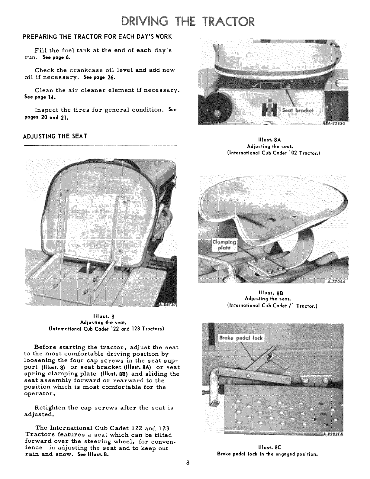
ADJUSTING THE SEAT
Illust. 8A
Adjusting the seat.
(International Cub Cadet 102 Tractor.)
Illust. 8
Adjusting the seat.
(International Cub Cadet 122 and 123 Tractors)
Before starting the tractor, adjust the seat
to the most comfortable driving position by
loosening the four cap screws in the seat sup-
port (Illust. 8) or seat bracket (lllust. SA) or seat
spring clamping plate (Illust. 8B) and sliding the
seat assembly forward or rearward to the
position which is most comfortable for the
operator.
Retighten the cap screws after the seat is
adjusted.
The International Cub Cadet 122 and 123
Tractors features a seat which can be tilted
forward over the steering wheel, for conven-
ience in adjusting the seat and to keep out
rain and snow. See |llust. 8.
Illust. 8B
Adjusting the seat.
(International Cub Cadet 71 Tractor.)
Illust. 8C
Brake pedal lock in the engaged position.
DRIVING THE TRACTOR
(InternationalCub Cadet 71, 102 and 122 Tractors)
CLUTCH AND BRAKE PEDAL
The combination clutch and brake pedal is
used to disengage the engine from the trans-
mission when shifting gears and to actuate the
brake to stop the tractor. The pedal must be
pressed all the way down to activate the safety
starting switch when starting the engine.
To disengage the clutch, press the pedal
approximately half way down. To stop the trac-
tor press the pedal all the way down.
LOCKING THE BRAKE
Always lock the brake when the tractor is
parked on a grade. To lock the brake, press
down on the brake pedal; then place the brake
pedal lock in the engaged position. To disen-
gage the lock, press down on the brake pedal
liftthe lock up and place it in the disengaged
position behind the brake pedal as shown in
Illust. 17A.
Note:Do not rest your foot on the pedal
while driving the tractor, as this will result
in excessive clutch lining wear.
Always be sure the rear wheels are free
to turn. Under any adverse conditions, do not
attempt to free the tractor by speeding up the
engine and suddenly engaging the clutch. Try
backing out instead of going forward.
STOPPING THE TRACTOR
Disengage the clutch by pressing the pedal
all the way down. Move the gearshift lever to
the neutral position.
CREEPER SHIFT LEVER
The creeper drive provides a slower speed
in each respective gear, by a four-to-one re-
duction in speed from direct drive. When the
creeper shift lever is all the way forward, it
is in direct drive, or all the way rearward, it
is in creeper drive. See Illust. 3. Note: Do not
use a mid-point position on the creeper drive
as neutral. Neutral position must be selected
only with the standard transmission gearshift
lever.
GEARSHIFT LEVER
This lever is used to select various gear
ratios provided in the transmission. There
are three forward speeds and one reverse
speed. See Illust. 3. Refer to "SPECIFICATIONS"
on page 32.
OPERATING THE CREEPER DRIVE
To operate the tractor in creeper drive,
move the creeper shift lever (illust. 3) all the
way rearward. Then select the speed desired
and proceed as instructed under "Starting the
Tractor".
STARTING THE TRACTOR
1. Advance the throttle lever slightly. See
Illust. 3.
Z. Disengage the clutch by pressing the
clutch pedal all the way down, and move the
gearshift lever to the desired speed.
3. Start the tractor in motion by slowly
releasing the clutch pedal and moving the
throttle lever to the position where the engine
operates best for the load to be handled.
Note: Do not shift gears while the engine
clutch is engaged or while the tractor is in
motion.
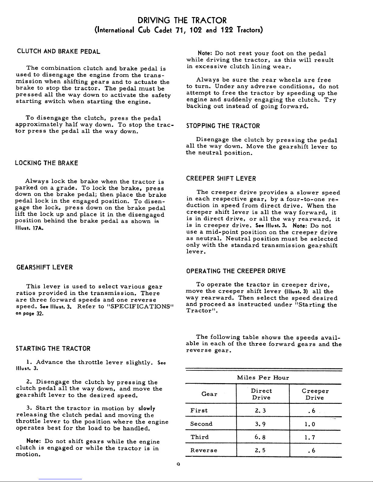
The following table shows the speeds avail-
able in each of the three forward gears and the
reverse gear.
Miles Per Hour
Gear
First
Second
Third
Reverse
Direct
Drive
Z. 3
3.9
6.8
Z. 5
Creeper
Drive
.6
1.0
1.7
.6
DRIVING THE TRACTOR
(InternationalCub Cadet 123 Tractor)
BRAKE PEDAL
The brake pedal must q_e pressed all the
way down to activate the safety starting switch.
When the brake pedal is in the depressed posi-
tion it automatically moves the speed control
lever to the "N" position.
The tractor can be stopped either by
pressing the pedal all the way down, or placing
the speed control lever in the "N" position.
LOCKING THE BRAKE
Always lock the brake when dismounting
from the tractor. To lock the brake, press
down on the brake pedal; then place the brake
pedal lock in the engaged position. See lllust.8C.
To disengage the lock, press down on the brake
pedal_ lift the lock up and place it in the dis-
engaged position behind the brake pedal as
shown inllIust.17A.
SPEED CONTROL LEVER
This lever is used to select any speeds
from a standstill "N" position to eight miles
per hour in the forward direction and to four
miles per hour in the reverse direction.
Moving the speed control lever forward
provides increased forward speeds, and mov-
ing the lever rearward provides the reversed
speeds.
Note: Do not rest your foot on the brake
pedal while driving the tractor as this would
cause the speed control lever to return to the
"N" position.
STARTING THE TRACTOR
I. Advance the throttle lever slightly.
Illust. 4.
See
g. Depress the brake pedal by pressing the
pedal all the way down, and move the towing
lever (Illust.4) in drive (horizontal) position,
then move the throttle lever to the position
where the engine operates best for the load to
be handled.
3. Start the tractor in motion by moving
the speed control lever forward or rearward
as de scribed above.
RELEASE LEVER
To push or move tractor for a short distance
or when working on the engine, the release le-
ver (Illust. 4) must be locked in the release
(down) position and the speed control lever must
be in the "N" position. Gaution: Do Not Tow.
STOPPINGTHE TRACTOR
Move the speed control lever to the "N"
position or use the brake. Before dismounting
always depress the brake pedal.
TRAILING EQUIPMENT TO THE
Trailing-type equipment must be hitched to
the tractor only at the hitch hole in the draw-
bar. Seelllusts. 11 and llA.
When the tractor has a three-point hitch
(lllusts. 11 and 11A) equipment adaptable to the
10
three-point hitch is raised and lowered with
the lift handle. The lift handle can be set to
hold the equipment at various positions by use
of the six notches in the lift handle quadrant.
The lower mounting bracket has three holes
which are used for additional adjustment.
 Loading...