

Break-in
mower
at
half throttle
INTRODUCTION
The International 105 Balanced Mower
is designed for use on the International Cub 8
Lo-Boye, Farmall Cub e, International and
Farmal18 Super A, Super A-l, 100, 130 and
140 Tractors. It is well suited for both industrial and farm use. A completing package
is required to mount on your tractor.
The tractors must be equipped with one of
the following units:
Touch Control for Farmall and hlternational
140 Basic Tractors for use with 105 Mowers
(Factory Application) (Standard Equipment on
hlternational 140 Standard Tractor).
354 467 R99 Special Touch Control for
Farmall and mternational"A", Super A,
100, 130, and 140 Tractors not previously
equipped with Touch Control.
for
first
This mower is especially built for highspeed mowing. It is ruggedly built with an
exclusive new wrist-action drive, balanced
for smooth running for longer machine life
and operator's comfort. It is especially
designed for cutting heavy hay and othervegetation.
or for mowing highway shoulders,
rights-of-way, and other industrial applications. It will operate efficiently with the cutter bar at any angle from. 450 below horizontal
to 900 vertical. This feature makes it desirable for cutting steep highway banks and
slopes. The. free floating action of the cutter
bar permits close operating positions along
the contour of the ground.
The hydraulic system enables the operatorto
raise the cutter bar to clear obstructions
or to raise the mowe r to transport position.
358 119 R 91 Special Touch Control Con-version
Package for Farmall and International
"A", Super A, 100, 130, and 140 Tractors
equipped with Touch Control.
381 223 R91 Restricted Actuator Package
(Factory Application) for International Cub
Lo-Boy, and Farrnall Cub Tractors.
381 228 R9l Restricted Actuator Package
(Field Conversion) for International Cub LoBoy and Farmall Cub Tractors.
Note: The Farmall Cub and International
Cub La-Boy tractors must be equipped withhead
gasket 351 989 R6.
The tractor Fast-Hitch cannot be used in
conjunction with the mower. However, the
Fast-Hitch helper spring parts are required
when the mower is mounted on the Cub or
Cub Lo-Boy Tractors.
The mower is mounted on the right side ofthe
tractor main frame between the front and
rear wheels. Power is transmitted from the
rear power take-off on the tractor through a
roller chain to the universal joint drive shaft.
A heavy-duty V -belt drive transmits the power
to the balanced drive. The entire drive is
completely shielded.
The mower operator can quickly adjust the
cutter bar for height to meet various mowing
conditions, permitting independent control ofthe
inner and outer shoes. A completing pack-
age is required for the International Cub Lo-
Boy and Farmall Cub Tractors.
A 5-foot cutter bar is standard equipment,
A variety of special knife assemblies areavailable
for this cutter bar.
Other special equipment and attachmentsare
as follows:
Outer Shoe Grass Deflector -to prevent
the cut material from falling into the un-
cut material.
Knife Rack Attachment -to carry extraknife
assembly in the field.
Curb Lift Attachment for International Cub
Lo-Boy and Farmall Cub Tractors -will
hold the inner shoe above ground level, up
to lO'l high to enable the cutter bar to be
placed in and position with the working
range of 45 below horizontal to vertical.
10hours
LUBRICA TION
Lubrication Guide
This machine is designed to require a
minimum amount of lubrication; however, regular and sufficient lubrication increases the
life of the machine, saves many dollars in
service parts, and is the best insurance
against delays.
Before starting, lubricate the complete
machine following the "Lubrication Guide",
and thereafter lubricate at regular intervals
as specified.
Care must be taken to see that all bearings
are lubricated their full length. To be certain
that all bearings are properly lubricated, the
lubricant should be forced into them until it
begins to appear at the sides.
Keep the lubricator gun clean and wipe off
all dirt from the lubrication fittings before
using the gun.
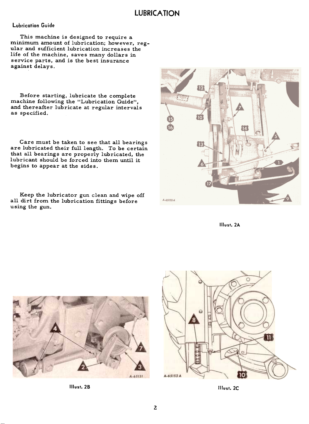
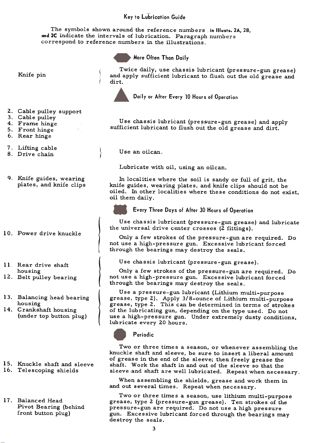
Illust. 2A
Illust.28
Illust.2C
2
Key to Lubrication Guide
The symbols shown around the reference numbers in Illusts. 2A, 2B,
and 2C indicate the intervals of lubrication. Paragraph numbers
correspond to reference numbers in the illustrations.
More Often Than Daily
Knife pin
2. Cable pulley support
3. Cable pulley4.
Frame hinge5.
Front hinge
6. Rear hinge
7.
Lifting cable
8.
Drive chain
Knife guides, wearing
plates, and knife clips
10.
Power drive knuckle
Twice daily, use chassis lubricant (pressure-gun grease)
and apply sufficient lubricant to flush out the old grease and
dirt.
Daily or After Every 10 Hours of Operation
Use chassis lubricant (pressure-gun grease) and apply
sufficient lubricant to flush out the old grease and dirt.
Use an oilcan.
Lubricate with oil, using an oilcan.
hllocalities where the soil is sandy or full of grit, theknife
guides, wearing plates, and knife clips should not be
oiled. hl other localities where these conditions do not exist,
oil them daily.
Every Three Days of After 30 Hours of Operati on
Use chassis lubricant (pressure-gun grease) and lubricate
the universal drive center crosses (2 fittings).
Only a few strokes of the pressure-gun are required. Do
not use a high-pressure gun. Excessive lubricant force_d
through the bearings may destroy the seals.
Rear drive shafthousing
Belt pulley bearing
13. Balancing head bearing
housirtg14.
Crankshaft housing
(under top button plug)
Knuckle shaft and sleeve16.
Telescoping shields
17. Balanced Head
Pivot Bearing (behind
fro~t button plug)
Use chassis lubricant (pressure-gun grease).
Only a few strokes of the pressure-gun are required. Do
not use a high-pressure gun. Excessive lubricant forced
through the bearings may destroy the seals.
Use a pressure-gun lubricant (Lithium mUlti-purpose
grease, type 2). Apply 3/8-ounce of Lithium mUlti-purpose
grease, type 2. This can be determined in terms of strokes
of the lubricating gun, depending on the type used. Do notuse
a high-pressure gun. Under extremely dusty conditions,lubricate
every 20 hours.
Periodic
Two or three times a season, or whenever assembling the
knuckle shaft and sleeve, be sure to insert a liberal amount
of grease in the end of the sleeve; then freely grease the
shaft. Work the shaft in and Qut of the sleeve so that the
sleeve .and shaft are well lubricated. Repeat when necessary.
When assembling the shields, grease and work them in
and out several times. Repeat when ~ecessary.
Two or three times a season, use lithium multi-purpose
grease, type 2 (pressure-gun grease). Ten strokes of the
pressure-gun are required: Do not use a high pressure
gun. Excessive lubricant forced through the bearings may
destroy the seals. .
3
9.
1112.
15.
ADJUSTING AND OPERATING
OPERATING
Before going into the field, check to see
that your machine is properly set up, adjusted,
and lubricated as in'structed.
Be sure all nuts are tight. They should be
tightened after a few hours of service. Spread
all cotters to keep them from falling out.
The wrist action drive is rugged and simple
designed to insure long life and trouble free
operation, however, its precision construction
requires a certain amount of break-in time.
Therefore, it is suggested that this mower be
run at. half (1/2) throttle under actual field
conditions for approximately the first 10 hours
This should be sufficient break-in time, after
which the mower can be operated at full speed.
During the break-in period the bearings will
run warmer than usual, but will not cause any
undue damage because of the unit being prepacked with "Lithium multi-purpose grease'!
as specified in the lubrication chart.
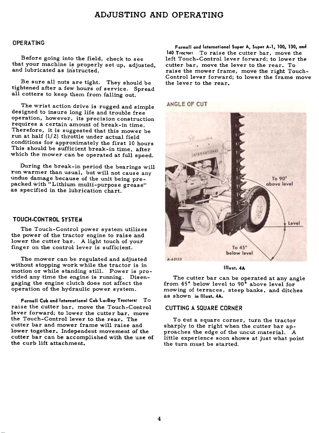
Farmall and Internatianal Super A, Super A.l, 100, 130, and
140 Tractor: To raise the cutter bar. move the
left Touch-Control lever forward; to lower the
cutter bar. move the lever to the rear. To
raise the mower frame. move the right TouchControl lever forward; to lower the frame move
the lever to the rear.
TOUCH.CONTROL SYSTEM
The Touch-Control power system utilizes
the power of the tractor engine to raise and
lower the cutter bar. A light touch of your
finger on the control lever is sufficient.
The mower can be regulated and adjusted
without stopping work while the tractor is in
motion or while standing still. Power is provided any time the engine is running. Disengaging the engine clutch does not affect the
operation of the hydraulic power system.
Farmall Cub and Internatianal Cub Lo.8oy Tractors: To
raise the cutter bar, move the Touch-Control
lever forward; to lower the cutter bar, move
the Touch-Control lever to the rear. The
cutter bar and mower frame will raise and
lower together. Independent movement of the
cutter bar can be accomplished with the use of
the curb lift attachment.
Illust. 4A
The cutter bar can be operated at any angle
from 450 below level to 900 above level for
mowing of terraces. steep banks. and ditches
as shown in Illust. 4A.
CUTTING A SQUARE CORNER
To cut a square corner, turn the tractor
sharply to the right when the cutter bar approaches the edge of the uncut material. A
little experience soon shows at just what point
the turn must be started.
4
CUTTER BAR LIFT
The cutter bar lift cable and lifting chain
should be set so that when the Touch-Control
lever is in the forward position, the cutter bar
will be approximately vertical. If the bar is
not vertical, this can be corrected by adjusting
the length of the cable and chain, either
lengthening or shortening.
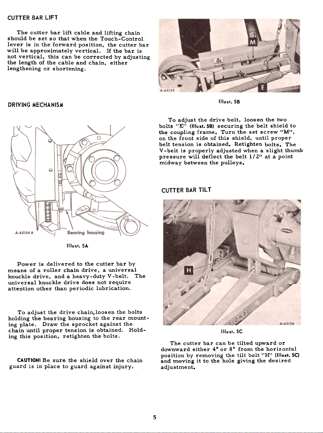
DRIVING MECHANISM
Illust. SA
Power is delivered to the cutter. bar by
means of a roller chain drive, a universal
knuckle drive, and a heavy-duty V-belt. The
univ~rsal knuckle drive does not require
attention other than periodic lubrication.
Illust. 58
To adjust the drive belt, loosen the two
bolts 'IE" (1IIust.58) securing the belt shield to
the coupling frame. Turn the set screw "M",
onthe front side of this shield, until proper
belt tension is obtained. Retighten bolts. The
V -belt is properly adjusted when a slight thumb
pressure will deflect the belt 1 (2" a.t a point
midway between the pulleys.
CUTTER BAR TILT
To adjust the drive chain,loosen the bolts
holding the bearing housing to the rear mount-
ing plate. Draw the sprocket against the
chain until proper tension is obtained. Holding this pos ition, retighten the bolts.
CAUTION! Be sure the shield over the chain
guard is in place to guard against injury.
Illust. SC
The cutter bar can be tilted upward or
downward either 40 or 80 from the horizontal
position by removing the tilt bolt "H" (1IIust.5C)
and moving it to the hole giving the desired
adju stme nt.
5
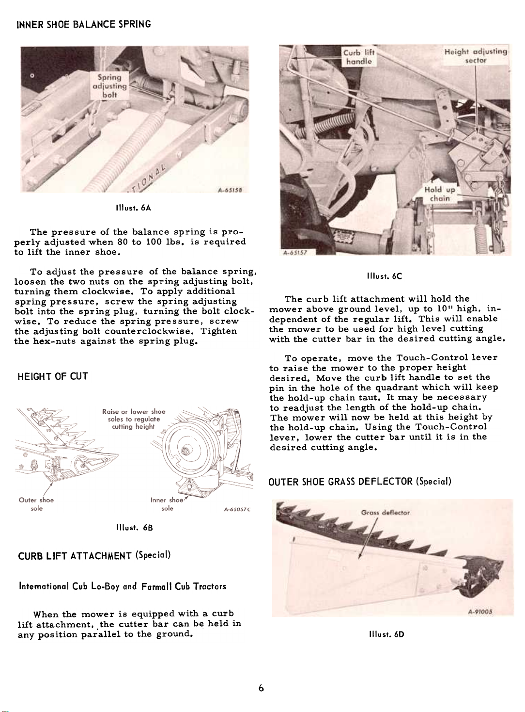
INNER SHOE BALANCE SPRING
Illust.6A
The pressure of the balance spring is pro-
perly adjusted when 80 to 100 Ibs. is required
to lift the inner shoe.
To adjust the pressure of the balance spring,
loosen the two nuts on the spring adjusting bolt,
turning them clockwise. To apply additional
spring pressure, screw the spring adjusting
bolt into the spring plug, turning the bolt clockwise. To reduce the spring pressure, screw
the adjusting bolt counterclockwise. Tightenthe
hex-nuts against the spring plug.
HEIGHT OF CUT
Illust. 68
Illust.6C
The cur b lift attachment will hold the
mower above ground level. up to 10" high, independent of the regular lift. This will enable
the mower to be used for high level cutting
with the cutter bar in the desired cutting angle.
To operate, move the Touch-Control lever
to raise the mower to the proper height
desired. Move the curb lift handle to set the
pin in the hole of the quadrant which will keep
the hold-up chain taut. It may be necessary
to readjust the length of the hold-up chain.
The mower will now be held at this height by
the hold-up chain. Using the Touch-Control
lever, lower the cutter bar until it is in the
desired cutting angle.
OUTER SHOE GRASS DEFLECTOR (Special)
CURB LIFT ATTACHMENT (Special)
International Cub Lo-Boy and Farmall Cub Tractors
When the mower is equipped with a curb
lift attachment. the cutter bar can be held in
any position parallel to the ground. Illust.6D
6

SERVICING THE CUTTER BAR
Increased acreages, mowing of pastures,
higher tractor speeds, and the greatly increased power of modern tractors subject
mowers to more severe usage than in thepast.
Therefore, periodic checking and ser-
vicing of your mower will pay big dividends
in a cleaner job of mowing, less damage to
parts, and decreased draft. Below are a few
suggestions pertaining to daily care of your
cutter bar:
Excessive draft is usually due to the fol-lowing:
A dull knife.
Poor lubrication.
Non-alignment of the cutter bar.
Poor adjustment of the cutter bar parts.
Bent guards must be reset to the proper
height 50 that all guards are at the same
height (level).
Do not hammer or bend down the lips of the
guards. This practice will result in choking
the knife, causing the mower to run hard.
NOTE: Do not raise the bar with the hydraulic
lift when the bar is "plugged" or "hung up" on
an obstruction. You may damage the bar.
Knife Section Riveting Tools
The knife section riveting tools will permit
the knife sections to be replaced without removing the knife assembly.
The knife is permanently registered at the
factory and no further adjustment is needed.
The knife must be straight. It must be supported by the wearing plates so that all sections contact the front of the ledger plate as
shown in Illust. 1A. Keep cutting apparatus in
perfect condition.
Ledger plates must be at the same height
(level) so that all sections contact. (Correct
installation of new guards is very important).
Correct tool usage for riveting
Illust.78
knife sections.
(Guards removed for clarity.)
Insert new rivets into the bottom of the
knife back and position the new knife section
onto the rivets.
Position the anvil tool "A" onto the rivet
head and tighten tool "A" until the tool and
tool holder is snug.
Tighten the heading tool "B" to secure therivet.
7

SERVICING THE CUTTER BAR. Continued
ledger Plate Riveting Tools
The ledger plate riveting tools will permit
the ledger plates to be replaced without re-
moving the guards.
Removing the Knife
Illust.88
Illust. SA
Correct tool usoge for riveting ledger plote.
knife.
Remove the old ledger plate and rivet, using
a 3/16-inch dia. punch at the flared end of the
rivet.
Position the new ledger plate onto the guard
and insert the new tubular rivet into the ledger
plate and guard.
Position the anvil tool rIG It onto the rivet
head an'd tighten tool IIG II until the tool and
tool holder is snug.
Tighten the flaring tool lID).! to flare the
rivet.
Illust.8C
Remove
8

SERVICING THE CUTTER BAR -Continued
Preparing and Replacing Guards
Remove broken guards and all dull ledgerplates.
must be pounded down to the proper height by
striking on the heavy section just ahead of the
plate. See Illust. 9A. Low guards must be raised
by striking the underside of this same loca-
tion.
NOTE: If guards are bent during field opera-
tion, remove the knife and bend the guard so
that it is at the correct height according to thegauge.
Steel Wearing Plates and Clips
The steel wearing plates support the back
of the knife so that the sections will contact
the ledger plate with a shearing action as
shown in Illust. 7A. If they are worn excessively,
the back of the knife will be low and the front
of the section will tip up, resulting in ragged
cutting. When this happens, they should be re-placed.
Illust.9A
When installing new guards make certain
that the bar is free of dirt. Draw the nut up
tight and then strike the guard several hammer
blows on the pad section of the countersunk hole
for the bolt. See Illust. 9A. This will seat the
guard. Then retighten the bolt.
Illust.98
Servicing the Kn ife
Illust. 9C
Check all old guards for correct ledger
plate height after reinstalling them, using the
ledger plate height gauge. The gauge must
rest flat against the slab and be flat on the
ledger plate to within 1/64 to 1/32 of an inch.
See Illust. 98. Guards which have been bent up
Remove all broken and dull sections as
shown in Illust. 9C;
9


DETACHING THE MOWER
Lower the cutter bar to the ground and dis-
connect the lifting cable.
With the lifting chain taut, remove the cap
screws from the left, right, and rear side
mounting plates.
CARE OF THE MOWER DURING STORAGE
STORING THE MACHINE
The life of the machine depends on how well
it is taken care of during the mowing season
and while in storage between seasons. The
storing period of the machine, which is
usually about eight months of each year, is an
important factor in the life of the machine.
Even though the machine is idle and not
subject to operational wear, it can, if not
properly stored, receive costly wear and
serious damage by being exposed to the
weather or by being struck by heavy objects.
No machine should be allowed to stand outside
unprotected from the weather for a long period
of time any more than an automobile.
Lower the mower frame to the ground and
disconnect the lifting chain.
Disconnect the power take-off.
Lubricate all points of the mower as shown
in the lubrication guide, and run the unit for
approximately ten minutes to allow lubricant
to give a protective coating to all bearings and
members subject to rust and corrosion.
Apply a light coating of oil on all expo sed
metal wearing parts.
Make a list of any service parts needed and
order these early. This will give your dealer
ample time to provide the parts and give you
sufficient time to install them before the next
mowing season.
A storage shed is a good investment be-
cause of the savings effected by assuring alonger-lasting
machine, reducing the operating
costs, and continuing the highly efficient mow-
ing performance.
BEFORE STORING THE MACHINE
Clean the machine of all dirt, trash, and
superfluous grease; if left on, it will hold
moisture and thus cause serious damage from
rust.
AFTER REMOVING THE MACHINE FROM STORAGE AND
This can save wasted time and needless expense.
ance with the instructions under "Lubrication"
to make sure that all bearings have a protective coating prior to field operation.
SETTING UP
Remove all wires and arrange the partsconveniently.
..
Lubricate all bearings and moving parts as
you proceed, and see that they work freely.
Bolts must be used in the holes in which
they are found, or in the parts to which they
are attached, unless otherwise shown.
are identified by 3 radial lines on the head and
are washer-faced to assure ma~mum surface
contact. See !llust. l1A.
BEFORE BEGINNING THE MOWING SEASON
the excess grease from the mower.
Make sure th~t all bolts and nuts are properly tightened.
Lubricate the machine thoroughly in accord-
Illust.llA
The cap screws furnished with this mower
Whenever the terms "left" and "right" areused,
it should be understood to mean from a
position behind and facing the machine.
Remove
When assembling this machine, start at the
beginning of the setting up instructions and
follow the sequence of steps for each assembly.
11

SIDE MOUNTING PLATES
Note: Side mounting plate cap screws must be tightened to 172 foot pounds torque.
International Cub Lo-Boy and Farmal! Cub Tractors
Illust. 12A
Left side mounting plates.
NOTE: If the mower is to be equipped with
the Knife Rack, assemble it on the side
mounting plate bolt at this time.
Internatianal and Farmall Super A, Super A-l, 100, 130, and
140 Tractors
Illust. 12C
Left side mounting plates.
NOTE: If the mower is to be equipped with
the Knife Rack, assemble it on the side
mounting plate bolt at this time.
Illust. 126
Right side mounting plotes.
NOTE: If the mower is to be equipped with
the Curb Lift. assemble it on the side mount-
ing plate bolts at this time.
Illust. 12D
Right side mounting plotes.
12


DRIVE SPROCKET AND CHAINS
International Cub Lo-Boy and Farmall Cub Tractors
Illust. 15A
International and Farmall Super A, Super A-l,
100,130, and 140 Tractors.
Illust. 15C
Illust. 158
15

CABLE LIFT ARM
BALANCED HEAD STOP
Illust. 16A
II lust. 16E
Internatianal Cub la-Boy Tractor.
1(lust. 16B
Internatianal Cub La-Bay
and Farmall Cub Tractars.
Illust. 16C
Internatianal Cub La-Bay
and Farmall Cub Tractars.
Note: Hole s are provided in the lift arm to
reposition the hammer strap when desired.
r Attach liftarm to rockshaft, using
1/2 x 2-1/2" and 3/4 x 2-1/2" cap
screws, lock washers and nuts
~- -cable around
I...
A-83375 -11/
Illust. 16D
International and Farmall Super A,
Super A-l, 100, 130, and 140 Tractors.
lift arm pivot
Attach pulley with ~haft
and 3/16x 1 "cotter pins
Farmall Cub and Internatianal and
Farmall Super A, Super A-I, 100, 130, and
Loole or "floppy" clothing should not be worn
by the operator because of the danger of it
wrapping on or getting into the moving parts.
Illust. 16F
140 Tractars.
---1-
16


KNIFE RACK (Special)
Internationa I Cub Lo-Boy Tractor
Assemble as illustrated, using the top bolt of the mounting plate and to
the inside of the fender, using two fender bolts 'IA".
International and Farmall Super A,
Super A-I, '],00, 130, and 140 Tractors
Illust. 19A
Assemble as illustrated.
19

CURB LIFT ATTACHMENT (Special)
International Cub Lo-Boy and Farmall Cub Tractors
Illust.20A
Illust. 208
Illust.20C
20

MEMBER, NATIONAL SAFETY COUNCIL
Accidents
with
No accident-prevention program can be successful without the wholehearted co-operation
of the person who is directly responsible for the
operation of equipment.
To read accident reports from allover the
country is to be convinced that a large number
of accidents can be prevented only by the
operator anticipating the result before the
accident is caused and doing something about
it. No power-driven equip.aent, whether it be
transportation or processing, whether it be on
the highway, in the harvest field or in the
Price $1.00
industrial plant, can be safer than the man who
is at the controls. If accidents are to be prevented-and they can be prevented-it will be
done by the operators who accept a full measure
of their responsibility.
It is true that the designer, the manufacturer,
the safety engineer can help; and they will help,
but their combined efforts can be wiped out by
a single careless act of the operator.
It is said that' 'the best kind of a safety
device is a careful operator. II We ask you
to be that kind of an operator.

 Loading...