

Page 1
TM
IEI prox.pad
plus Access System
Installation/Programming Manual
www.ieib.com prox.pad plus Installation/Programming
Manual
Copyright 2003 Part Number 6105679, Rev. 1.0
International Electronics, Inc.
PPP, D2
Page 2

For more information, contact:
International Electronics, Inc. © Copyright 2003
427 Turnpike Street International Electronics, Inc.
Canton, MA 02021 U.S.A. All Rights Reserved
Published in U.S.A.
Telephone:
781-821-5566
800- 733-9502 (sales in MA)
800-343-9502 (sales)
Fax: 781-821-4443
Fax
Information
Center: 781-821-0734
Internet:
www.ieib.com
PPP, D2
Page 3

Table of Contents
Chapter 1: Introduction
1.1 About this Manual ............................................... 1-1
1.2 Safety Warnings and Cautions..........................1-1
1.3 Design Change Disclaimer.................................1-1
1.4 Reproduction Disclaimer.................................... 1-1
1.5 Technical Support................................................ 1-1
1.6 Warranty................................................................ 1-2
1.7 Items Supplied from the Factory ...................... 1-3
1.8 Items the Installer Must Supply........................1-3
1.9 General Description............................................. 1-4
1.9.1 Design Function ............................................ 1-4
1.10 prox.pad plus Operation .................................. 1-5
Chapter 2: Installation
2.1 Installation Configurations................................. 2-1
2.2 Other Installation Considerations..................... 2-2
2.2.1 Power Supply/Current Requirements....... 2-2
2.2.2 Gang Box and Mounting .............................2-2
2.2.3 Mounting the Unit on Metal....................... 2-2
2.2.4 RF Interference .............................................. 2-2
2.3 Checking the Cables............................................ 2-3
2.4 Mounting the prox.pad plus Unit .................... 2-7
2.4.1 Performing a Wall Mounted Installation.. 2-7
2.4.2 Performing a Glass Mounted Installation. 2-9
2.4.3 Performing a Secure Installation................2-11
2.5 Inserting Circuit Boards...................................... 2-15
2.6 Defaulting prox.pad plus Memory................... 2-16
prox.pad plus Install/Program. Manual, PPP, D2 iii
Page 4

Table of Contents
Chapter 3: Wiring
3.1 Wiring the prox.pad plus Unit...........................3-1
3.1.1 Wiring the AUX Relay for Use as Alarm
Shunt .........................................................................3-1
3.1.1.A Wiring the Alarm Shunt Relay...........3-1
3.1.2 Wiring the AUX Relay for Use as Forced
Door...........................................................................3-3
3.1.2.A Wiring the Forced Door Relay ...........3-3
3.1.3 Wiring the AUX Relay for Use as
Propped Door ..........................................................3-5
3.1.3.A Wiring the Propped Door Relay........3-5
3.1.4 Wiring the Door Contact Input...................3-7
3.1.5 Wiring the REX Switch (Request to Exit) ..3-9
3.1.6 Wiring the Main Relay..................................3-11
3.2 prox.pad plus Communications ........................3-13
3.3 Networking Multiple prox.pad plus Units
Together .......................................................................3-14
3.4 Testing the prox.pad plus...................................3-16
3.4.1 Testing the Controller/Keypad....................3-16
Chapter 4: Programming
4.1 Programming Overview .....................................4-1
4.1.1 Programming from the Keypad..................4-1
4.1.1.A Master Code (User #1) ........................4-1
4.1.1.B Supervisor Code (user #2) ..................4-2
4.1.1.C Master Code and Supervisor Code
Special Features..................................................4-2
4.1.1.D prox.pad plus Default Settings ..........4-3
4.1.1.E Resetting the Master Code and
System Defaults Only .......................................4-5
4.1.1.F Erasing Entire Memory/Resetting
System Defaults..................................................4-6
iv prox.pad plus Install/Program. Manual, PPP, D2
Page 5

Table of Contents
4.2 Programming Users.............................................4-7
4.2.1 Adding New or Changing Existing
Codes/Cards ............................................................ 4-7
4.2.2 Programming Code and Card Options .... 4-7
4.2.2 Programming User Types............................ 4-8
4.2.2.A Programming User Data,
Command 50, Full Format .............................. 4-9
4.2.2.B Quick Program Feature....................... 4-10
4.2.2.C Programming Code ONLY Use ........4-10
4.2.2.D Programming Code AND Card Use 4-10
4.2.2.E Programming Card ONLY Use ......... 4-11
4.2.2.F Programming Code OR Card............. 4-11
4.2.3 Batch Load Cards by Presentation............. 4-12
4.2.4 Enabling/Disabling Users Command ........ 4-13
4.2.5 Batch Load Cards Manually
(without presentation)........................................... 4-14
4.2.6 Block Delete of Users ...................................4-15
4.2.7 Deleting Users ............................................... 4-15
4.3 Programming Outputs........................................ 4-16
4.3.1 Changing the Lock Output Time............... 4-16
4.3.2 Assigning Outputs ........................................ 4-16
4.3.3 Setting Propped Door Output Time ......... 4-18
4.3.4 Setting Forced Door Output Time ............. 4-18
4.4 Programming Keypad Options and
Parameters................................................................... 4-19
4.4.1 User Lockout Option....................................4-19
4.4.1.A Lockout By Location............................ 4-19
4.4.1.B Lockout By Group................................ 4-20
4.4.2 TimeZone/Holiday Features........................4-21
4.4.2.A Midnight Crossing TimeZones..........4-22
4.4.2.B Holidays .................................................4-23
4.4.2.C Daylight Savings Time ........................ 4-23
4.4.2.D Leap Year .............................................. 4-24
prox.pad plus Install/Program. Manual, PPP, D2 v
Page 6

Table of Contents
4.4.2.E Time/Date Set.........................................4-24
4.4.3 Turning Visual LED/Keypress Indicator
ON/OFF....................................................................4-24
4.4.4 Turning Audio Keypress Feedback
ON/OFF....................................................................4-25
4.4.5 Error Lockout .................................................4-26
4.4.6 Timed Anti-Passback.....................................4-27
4.5 Using the Printing Features................................4-29
4.5.1 Selecting Transaction L og Information......4-29
4.5.2 Printing a Transaction Log...........................4-30
4.5.2.A Programming a Transaction Dump
Code .....................................................................4-31
4.5.2.B Printing a Transaction Log
Manually..............................................................4-31
4.5.2.C Erasing a Transaction Log...................4-32
4.5.2.D Printing a Programmed Users List ....4-32
4.6 Programming Commands ..................................4-34
Chapter 5: Troubleshooting
5.1 Before Calling IEI .................................................5-1
5.2 Flow Charts ...........................................................5-4
5.3 Performing Power Supply Integrity Test .........5-6
5.4 Correcting Possible Water Problems.................5-9
5.4.1 Silicone.............................................................5-9
5.4.2 Wire Run .........................................................5-9
Chapter 6: Miscellaneous
Information
6.1 Customer Service Policy......................................6-1
6.2 RMA Policy ............................................................6-2
vi prox.pad plus Install/Program. Manual, PPP, D2
Page 7

List of Illustrations
Figure 2-1 prox.pad plus Wiring Harness.........2-3
Figure 2-2 Identifying Pin Connectors ..............2-4
Figure 2-3 Performing a Wall Mounted I
nstallation.............................................2-8
Figure 2-4 Performing a Glass Mounted
Installation...........................................2-10
Figure 2-5 Performing a Secure Installation .....2-12
Figure 2-6 Removing/Inserting Printed Circuit
Board ....................................................2-15
Figure 2-7 Program Button Location on Main
Circuit Board .......................................2-17
Figure 3-1 Wiring the Aux Relay for Alarm
Shunt Operation.................................3-2
Figure 3-2 Wiring the Aux Relay for Forced
Door Alarm..........................................3-4
Figure 3-3 Wiring the Aux Relay for Propped
Door Alarm..........................................3-6
Figure 3-4 Wiring the Door Contact Input .......3-8
Figure 3-5 Wiring the REX Switch .....................3-10
Figure 3-6 Electric Strike (Fail Secure)
Wiring Diagram..................................3-11
Figure 3-7 MagLock (Fail Safe) Wiring
Diagram................................................3-12
Figure 3-8 Connecting the prox.pad plus to a
PC COM Port ......................................3-13
Figure 3-9 Connecting the prox.pad plus to a
Network ............................................... 3-14
Figure 3-10 Networking Multiple prox.pad
plus Units Together ...........................3-15
prox.pad plus Install/Program. Manual, PPP, D2 vii
Page 8

List of Illustrations/List of Tables
List of Tables
Table 1-1 prox.pad plus Specifications ............ 1-6
Table 2-1 prox.pad plus Pin Connections .......2-5
Table 2-2 IEI-Supplied Parts/Optional Items.. 2-6
Table 4-1 prox.pad plus Default Settings........ 4-3
Table 4-2 LED Indicators/Sounder
Table 4-3 prox.pad plus User Types ................ 4-8
Table 5-1 Troubleshooting Chart ...................... 5-2
Operations........................................... 4-4
viii prox.pad plus Install/Program. Manual, P PP, D2
Page 9

Chapter 1:
Introduction
1.1 About this
Manual
1.2 Safety
Warnings and
Cautions
1.3 Design
Change
Disclaimer
1.4 Reproduction
Disclaimer
1.5 Technical
Support
This manual is designed for installers of the International Electronics prox.pad plus Access System.
When handling the main printed circuit board, to
guard against possible static discharges, touch a
grounded object BEFORE touching the prox.pad plus
unit. Static shock can render the product unusable.
Due to design changes and product improvements,
information in this manual is subject to change without
notice. IEI assumes no responsibility for any errors that
may appear in this manual.
Neither this manual nor any part of it may be reproduced, photocopied, or electronically transmitted in
any way without the written permission of IEI.
Should you experience any difficulty installing the
prox.pad plus unit, please contact your IEI representative, or IEI at the number listed on page ii. Before
calling IEI for installation assistance, refer to Chapter
5, Troubleshooting. This chapter includes a list of com-
mon system problems, possible causes, and corrective
actions plus easy-to-use diagnostic flow charts.
To contact IEI’s Technical Support department, call
1-800-343-9502 between 8:00 a.m. - 7:00 p.m. (Eastern
Standard Time), Monday through Friday. Questions
can also be submitted through our website at
www.ieib.com. You can also download an electronic
version of this manual from this site.
prox.pad plus Install/Program. Manual, PPP, D2 1-1
Page 10

Chapter 1: Introduction 1.6 Warranty
1.6 Warranty
International Electronics Inc. (IEI) warrants its products to be free from defects in material and workmanship when they have been installed in accordance with
the manufacturer’s instructions and have not been
modified or tampered with. IEI does not assume any
responsibility for damage or injury to person or property due to improper care, storage, handling, abuse,
misuse,normalwearandtear,oranactofGod.
IEI’s sole responsibility is limited to the repair (at IEI’s
option) or the replacement of the defective product or
part when sent to IEI’s facility (freight and insurance
charges prepaid) after obtaining IEI’s Return Material
Authorization. IEI will not be liable to the purchaser
or any one else for incidental or consequential damages arising from any defect in, or malfunction of, its
products.
Except as stated above, IEI makes no warranties, either
expressed or implied, as to any matter whatsoever,
including, and without limitation to, the condition of
its products, their merchantability, or fitness for any
particular purpose.
Warranty Periods Are:
1 Year PowerKey
2 Years Door Gard & Secured Series
Products
2 Years prox.pad and prox.pad plus
2 Years LS Series
2 Years Glass Break
5 Years ‘e’ Series Keypads
All products have date code labeling to determine the
warranty period. A 90-day grace period is added to all
products to account for shelf life.
1-2 prox.pad plus Install/Program. Manual, PPP, D2
Page 11

1.7 Items Supplied from the Factory Chapter 1: Introduction
1.7 Items Supplied
from the Factory
1.8 Items the
Installer Must
Supply
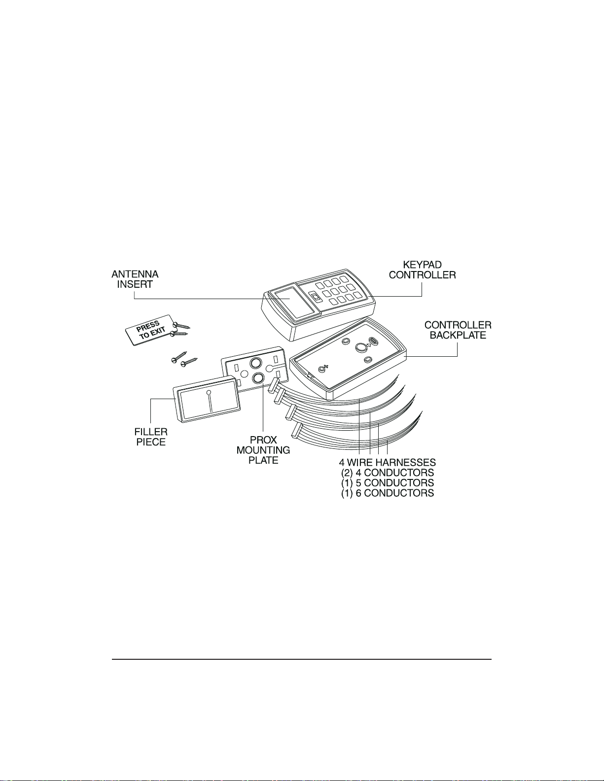
The following items are supplied from the factory with
the initial prox.pad plus shipment.
• Controller with Keypad, Faceplate, Request to Exit
(REX) button (also called the “Filler Piece”), three
Wire Harnesses, and various installation Screws.
For each initial prox.pad plus unit installation, the
installer must supply the following items:
• The prox.pad plus unit works with these four
types of cards:
–ProxCardII
–IsoProxII
–DuoProxII
–ProxkeyFOB
• an appropriately rated DC Power Supply (12 VDC)
(filtered and regulated recommended)
• the appropriate installation electrical tools
• the recommended remote antenna cable
[ALPHA 1174C (22AWG) 4-wire, stranded] (this is
required ONLY if you choose to remote the antenna 10 feet away from the keypad/controller)
• RS-485 cable (24AWG), shielded, two twisted-pair
telephone cable with a shunt capacitance of
16 pF/Ft (required only when using software)
• power supply cable (18AWG-22AWG) 2-wire
stranded (depends on distance)
• door lock cable (18AWG-22AWG) 2-wire stranded
(depends on distance)
• door monitor cable (18AWG-22AWG) 2-wire
stranded (depends on distance)
• REX cable (if using remote switch) 2-wire stranded
prox.pad plus Install/Program. Manual, PPP, D2 1-3
Page 12

Chapter 1: Introduction 1.9 General Description
1.9 General
Description
1.9.1 Design Function
The IEI prox.pad plus Access System provides card
and/or keypad access control for a single door. The
unit can be install ed in a one-stage configuration
(which is typical for most users), or a higher security,
two-stage (or “remote”) configuration.
In the “secure” (or remote) configuration, the antenna
can be detached and mullion-mounted up to a maximum of 10 feet away from the controller/keypad. For
installation details, see section 2.4.3.
Theprox.padplusunitiscompatiblewithallHID
proximity cards, with up to 40 bits. Batch programming
without the need for the card can be done only with
26-bit HID cards. All programming is performed using
the built-in keypad.
The prox.pad plus unit is equipped with RS-485 communications, which allows the system to be managed
with a personal computer using Hub Manager
TM
Professional software (ver. 5 or higher). This capability
allows the unit to store up to 8 timezones, including
auto-unlock, and a maximum of 32 holidays. In addition, the unit can store up to 2,000 transactions.
The keypad can store up to 2,000 users.
The specific types of users that can be programmed
with the prox.pad plus unit are listed in Table 1-1 on
page 1-8.
For convenience, proximity cards can be programmed
efficiently in a “batch” mode. A user-programmable
lock time of 1-255 seconds plus a “latch/toggle” mode
are included.
1-4 prox.pad plus Install/Program. Manual, PPP, D2
Page 13

1.10 prox.pad plus Operation Chapter 1: Introduction
1.10 prox.pad plus
Operation
Once installed and programme d successf ully, the
prox.pad plus controller stores all transactions and
controls all outputs. The controller receives data sent
to it from the proximity reader, decides if access should
be provided or not, and then energizes the door lock
or not, locking or unlocking the door.
The prox.pad plus unit includes two relay outputs
(located internally), an internal clock, programming
keypad, and memory chips to store user information
and a transaction data log.
An external IR (infrared) LED/port/transmitter at the
top right of the prox.pad plus controller allows for
printing of the Transaction Log and the Programmed
User List to the optional IEI PDA Data Capture Device
(DCD) software. Chapter 4 discusses printing reports.
NOTE: IEI recommends that first-time installers test
the prox.pad plus unit BEFORE actually mounting
and wiring the unit to become familiar with its operation (see Chapter 2).
prox.pad plus Install/Program. Manual, PPP, D2 1-5
Page 14

Chapter 1: Introduction 1.10 prox.pad plus Operation
Table 1-1. prox.pad plus Specifications
ELECTRICAL
Power Supply/Current
Requirements
WIRING
Remote Antenna Cable ALPHA 1174C (22AWG) 4-wire, stranded (this is
RS-485 Cable 24AWG, shielded, two twisted-pair telephone cable
Power Supply Cable 18AWG - 22AWG 2-wire stranded (depends on
Door Lock Cable 18AWG - 22AWG 2-wire stranded (depends on
Door Monitor Cable 18AWG - 22AWG 2-wire stranded (depends on
REX Cable (if using remote switch) 2-wire stranded
MECHANICAL
Height 5.25 in (13.3 cm)
Width 2.75in(7cm)
10-15 VDC, linear filtered and regulated power supply
500 mA (not including locking device or peripherals)
required ONLY if you choose to remote the antenna
10 feet away from the keypad/controller)
with a shunt capacitance of 16 pF/Ft (required only
when using software)
distance)
distance)
distance)
Depth 1.375 in (3.5 cm)
RELAY OUTPUTS
Main Relay - Form C (switches up to 4A)
Aux Relay - Form C (switches up to 1A)
MONITOR INPUTS
Door Position (Normally Closed, dry contact)
Request to Exit (REX, Normally Open, dry contact)
1-6 prox.pad plus Install/Program. Manual, PPP, D2
Page 15

1.10 prox.pad plus Operation Chapter 1: Introduction
Table 1-1. prox.pad plus Specifications (continued)
OTHER OUTPUTS
Infrared output to optional IEI DCD PDA program
SOUNDER 4000 Hz, defeatable
LEDs Bi-Color (red/green)
Yellow
COMPATIBLE
PROXIMITY CARDS
UNIT CAPACITY
Users 2,000 users maximum; each user can have a
Transactions 2,000 transactions maximum; each transaction
Lock Time 1-255 seconds
Lock Mode Access Time or Toggle/Latch
ALARM OUTPUT One of these three events can be programmed:
USER ACCESS
CONFIGURATIONS
All 26-bit HID card, including the following: ProxCard
II, IsoProx II, Duo Prox II, and Proxkey FOB; 26-bit
cards are required for manual or batch programming
card/tag, a PIN code, or a card/tag plus a PIN code
includes time, date, user “slot number,” and event
Alarm Shunt Relay, Forced Door Relay, or Propped
Door Relay
Code ONLY
Code AND Card
Card ONLY
Code OR Card
prox.pad plus Install/Program. Manual, PPP, D2 1-7
Page 16

Chapter 1: Introduction 1.10 prox.pad plus Operation
Table 1-1. prox.pad plus Specifications (continued)
PROGRAMMABLE
USER TYPES
SYSTEM USES/
INSTALLATION
CONFIGURATIONS
ENVIRONMENTAL Indoor or outdoor
Operating Temperature -31° to 150° F (-35° to 66° C)
Operating Humidity 5% to 95% relative humidity, non-condensing
Each user is assigned one of the following user types:
0-Toggle/latch strike
1-Normal access
2-log Dump
3-Lockout
4-Extended unlock
5-Single use
6-Relock
7-Emergency
Suitable for small installations or remote locations,
indoors or outdoors
Wall mounted, glass mounted, or secure installation
1-8 prox.pad plus Install/Program. Manual, PPP, D2
Page 17

Chapter 2: Installation
Chapter 2 supplies information about prox.pad plus
installation configurations; installation considerations;
and procedures for checking the cables, mounting the
prox.pad plus unit, inserting circuit boards, and defaulting prox.pad plus memory.
2.1 Installation
Configurations
It is the installer’s responsibility to determine the appropriate prox.pad plus installation configuration,
which differs from installation to installation. These
three installation configurations are possible:
• Wall mounted installation (exterior to the room
to be accessed). In this configuration, a single gang
electrical box can be used. Typically, the pr ox.pad
plus unit is wall mounted (surface mounted) outside the access area on the unsecured side.
• Glass mounted installation, using the four IEI-
supplied pressure-sensitive adhesive pads. In this
configuration, the prox.pad plus unit is affixed
with the adhesive pads to the glass door or the
window adjacent to the door being accessed, on
the interior side of the glass. The side cut-out on
the unit is used to bring the wires out of the side
of the prox.pad plus case.
• Secure installation (or “two-stage” configuration),
for higher security. In this configuration, the
prox.pad plus antenna is located a maximum of
10 feet away from the controller/keypad; the controller/keypad is located on the secure side of the
door.
prox.pad plus Install/Program. Manual, PPP, D2 2-1
Page 18

Chapter 2: Installation 2.2 Other Installation Considerations
2.2 Other
Installation
Considerations
2.2.1 Power
Supply/Current
Requirements
2.2.2 Gang Box and
Mounting
2.2.3 Mounting the
Unit on Metal
Sections 2.2.1-2.2.4 describe important considerations
the installer must decide upon before actually starting
to install and wire the prox.pad plus unit.
Power for the prox.pad plus unit must be from a minimum 10-15 volt DC linear, filtered and regulated
power supply. It is typical for the chosen power supply
to power BOTH the prox.pad plus unit and the selected locking device. When using one power supply
for both the prox.pad plus unit and locking device, be
sure to include both devices in your current requirements calculations.
NOTE: IEI recommends that you ground the power
supply to earth ground.
For the wall mounted installation configuration, a single gang electrical box can be used. (Typically, the
prox.pad plus unit is wall mounted outside the access
areaontheunsecuresideofthedoor.)
The prox.pad plus unit uses radio frequency to transfer
power to and communicate with the proximity card
or keytag. If the antenna is mounted directly on a metal
building or wall, some of the energy is absorbed by
the metal, resulting in less power being transmitted to
the keytag; this causes reduced read range. If you must
mount the prox.pad plus unit on metal, test the unit
in place before permanently installing it. If read range
distance distance is not adequate, a non-metallic spacer
can be fabricated and installed between the unit’s antenna and the metal mounting surface.
2.2.4 RF Interference
2-2 prox.pad plus Install/Program. Manual, PPP, D2
The prox.pad plus unit should not cause interference
to other equipment as it is designed to meet FCC
guidelines. However, other devices can interfere with
prox.pad plus operation.
Page 19
2.3 Checking the Cables Chapter 2: Installation
Avoid locating the prox.pad plus unit closer than 3 feet
(1 meter) to a computer monitor or television or another prox.pad plus unit. If you believe you are experiencing reduced read range due to interference, try
repositioning the prox.pad plus unit, remoting the antenna, or relocating other nearby electrical equipment.
2.3 Checking the
Cables
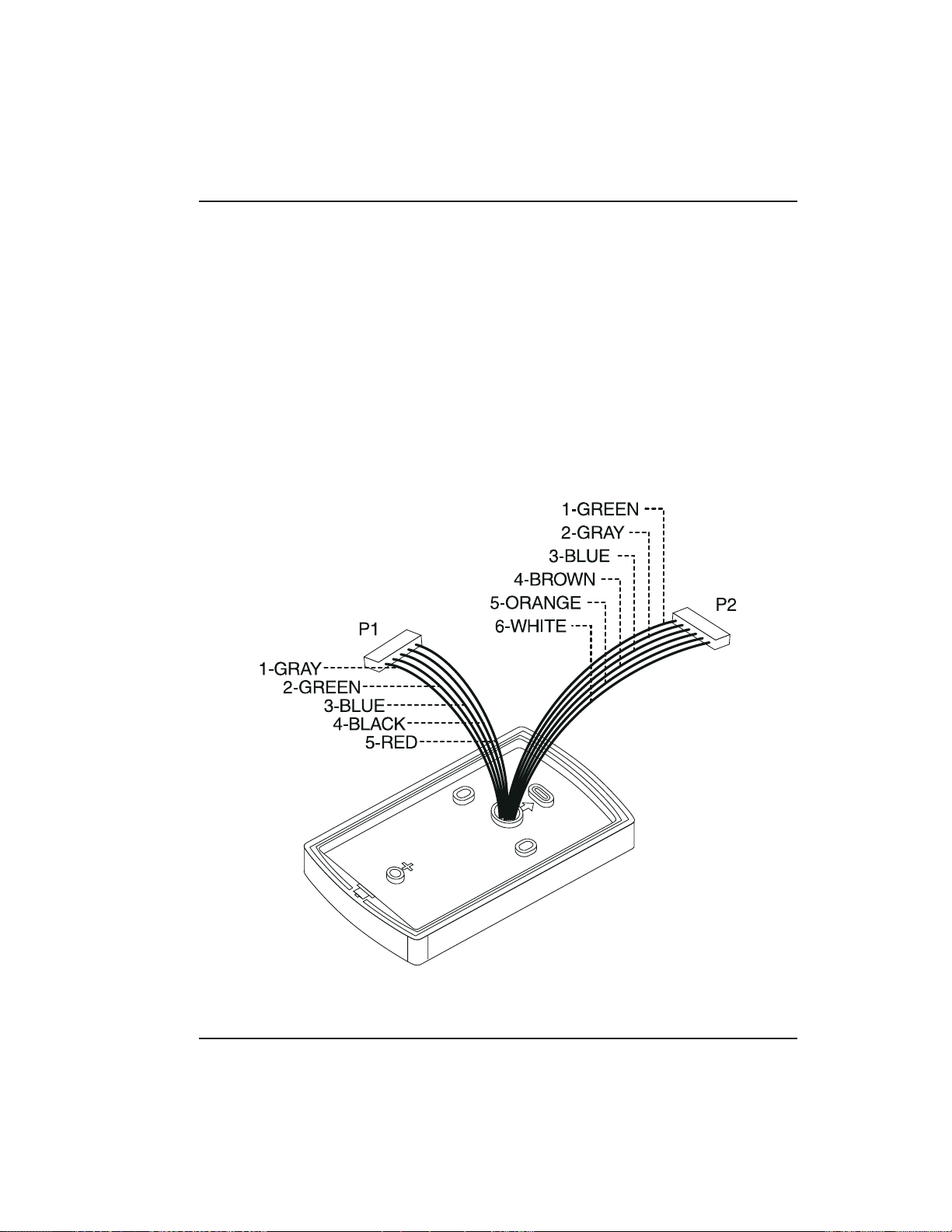
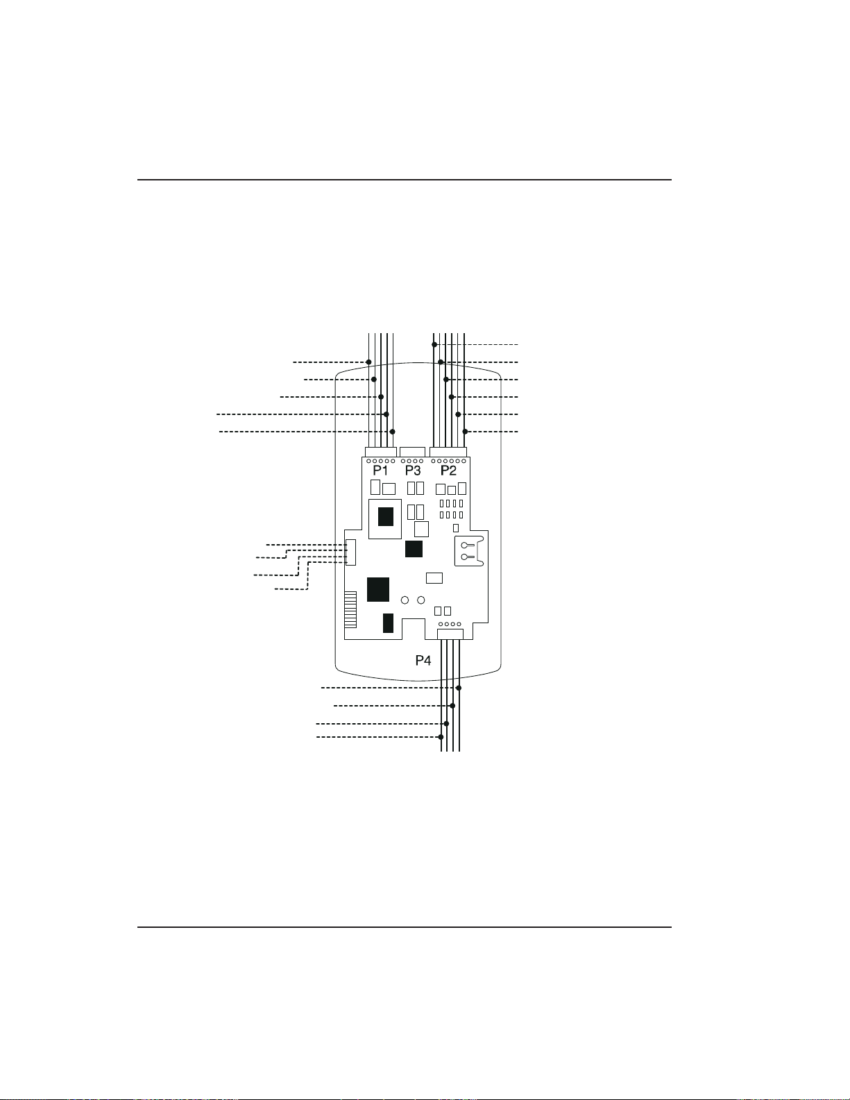
Figure 2-1 below provides a detailed illustration of the
prox.pad plus wiring harness. Figure 2-2 illustrates the
Pin connectors on the main circuit board; Table 2-2
describes these four Pin connectors, P1, P2, P4, and P5.
Figure 2-1 prox.pad plus Wiring Harness
prox.pad plus Install/Program. Manual, PPP, D2 2-3
Page 20
S
F
C
1
2
3
4
5
)
)
n)
Chapter 2: Installation 2.3 Checking the Cables
1-Green (Aux Relay N/O
-Gray (Main Relay N/C)
-Green (Main Relay N/C)
-Blue (Main Relay C)
-Black (-V)
-Red (+V
ystem Power: 12VDC
or RS-485
ommunications
1-Blue (Terminator)
2-Brown (Data A)
3-White (Data B)
4-Green (Data GND)
)
1-Red (Bi Color LED)
2-Black (Bi Color LED)
3-White (Antenna +)
4-White (Antenna -)
P5
Connections for remote
installation of proximity
antenna
2-Gray (Aux Relay N/C
3-Blue (Aux Relay C)
4-Brown (REX Loop)
5-Orange (Door Loop)
6-White (Loop Commo
NOTE: P3 Not Used
Figure 2-2 Identifying Pin Connectors
2-4 prox.pad plus Install/Program. Manual, PPP, D2
Page 21

2.3 Checking the Cables Chapter 2: Installation
Table 2-2. prox.pad plus Pin Connectors
Pin Connector (on
main circuit board)
P1 (5-pin connector, top
left-most location)
P2 (6-pin connector, top
right-most location)
Description/Use
Pin Wire Color Use
1 GRAY Main Relay, N ormally
Closed (N.C.)
2 GREEN Main Relay, Normally
Open (N.O.)
3 BLUE Main Relay, Common
4BLACK Ground
5RED PowerIn,+12VDC
Pin Wire Color Use
1GREEN AuxRelayN.O.
2 GRAY Aux Relay N.C.
3 BLUE Aux Relay Common
4 BROWN REX Loop (if used) (NO
contact)
5 ORANGE Door Loop Contact (NC
contact)
6 WHITE Loop Common (shared by
REX and door loop)
NOTE: Pins 1, 2, 3 can be wired at the installer’s option for
one of the following alarm outputs, Alarm Shunt, Forced
Door, or Propped Door. Mandatory: If you do not wish to
install door contacts per Figure 2-5, twist white and orange
wires together. If not done, REX input will not work.
P4 (4-pin connector,
bottom location)
Pin Wire Color Use
1 RED Bi-Color LED (Red +)
2 BLACK Bi-Color LED (Green +)
3 WHITE Antenna (no polarity)
4 WHITE Antenna (no polarity)
P-5 (4-pin connector,
left-hand side location)
Pin Wire Color Use
1Blue Terminator
2Brown DataA
3 White Data B
4 Green Data GND
prox.pad plus Install/Program. Manual, PPP, D2 2-5
Page 22

Chapter 2: Installation 2.3 Checking the Cables
Table 2-3. IEI-Supplied Parts/Optional Items
Quantity Description
1 Keypad/control unit assembly, with Prox Sensor, Backplate,
hex socket screw
1 Filler Piece/REX Button
1PresstoExitLabel
4 Wall Anchors
4MountingScrews
1 Antenna Backplate for remote mounting
1 Silicone Rubber “dogbone”
4 Self-Adhering Pads (for glass mounting)
1 Installer Guide
1 CD-ROM containing instruction manuals
4 Cable Assemblies
1TamperScrew
Optional Items
1 Replacement Battery: Panasonic B R1225 or equivalent
lots of 25 only ProxKey Keytags (IEI part number 0297301)
lots of 25 only ProxCard II Cards (IEI part n umber 0297401)
1 Hub Manager
TM
Professional PC Software (version 5 or
higher)
1 IEI Data Collection Device (DCD) PDA Software
2-6 prox.pad plus Install/Program. Manual, PPP, D2
Page 23

2.4 Mounting the prox.pad plus Unit Chapter 2: Installation
2.4 Mounting the
prox.pad plus Unit
2.4.1 Performing a
Wall Mounted
Installation
Select one of these three installation configurations,
wall mount, glass mount, or secure as appropriate for
this installation. Then refer to sections 2.4.1-2.4.3.
This section provides general considerations when
performing a wall mounted installation. T ypically, the
prox.pad plus unit is mounted on a flat, level surface
(drywall, masonry, wood, etc.) exterior to the room to
be accessed. A single-gang electrical box (or “back box”)
can be used. Typically, the prox.pad plus unit is wall
mounted outside the access area on the unsecure side
of the door.
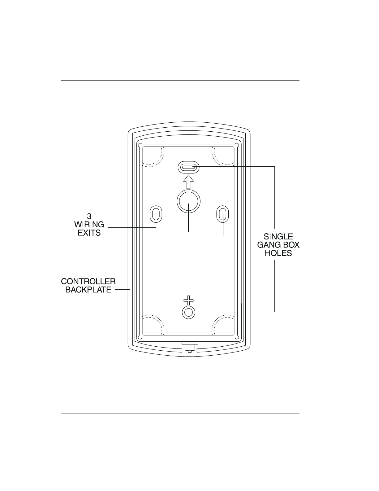
Figure 2-3 illustrates the components on the prox.pad
plus unit used for wall mounting. Two “single-gang
box” holes align with two corresponding holes in the
single-gang box. A “wire” exit knockout is supplied
through which the prox.pad plus wiring is pulled. A
typical wall mounted installation proceeds as follows:
1. Secure a single-gang box to the desired location.
2. “Punch out” the two single-gang box connectors
on the controller backplate of the prox.pad plus
unit.
3. Disconnect the controller backplate of the
prox.pad plus unit from the front keypad/controller. Align the two single-gang box connectors on
the controller backplate over the two corresponding holes on the single-gang box, previously secured at step 1.
4. Secure the backplate to the single-gang box by
inserting/tightening two screws into the two single-gang box holes.
5. Connect the front keypad/controller to the back
housing.
6 Pull the prox.pad plus wiring through the wiring
exit as appropriate.
7. Install the tamper screw into the hole at the bottom
front of the enclosure using a #6 spanner bit (not
included, but available from IEI).
prox.pad plus Install/Program. Manual, PPP, D2 2-7
Page 24
Chapter 2: Installation 2.4 Mounting the prox.pad plus Unit
Figure 2-3 Performing a Wall Mounted
Installation
2-8 prox.pad plus Install/Program. Manual, PPP, D2
Page 25

2.4 Mounting the prox.pad plus Unit Chapter 2: Installation
2.4.2 Performing a
Glass Mounted
Installation
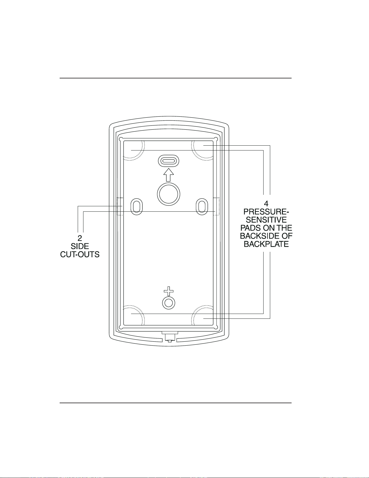
Figure 2-4 shows the four IEI-supplied pressure-sensitive adhesive pads and the two side cut-outs used
for this installation. In this configuration, the prox.pad
plus unit is affixed with the four self-adhesive pads to
the glass or the glass window adjacent to the controlled
door being accessed, on the interior side of the glass.
Oneofthetwosidecut-outsisusedtobringthewires
out of the side of the prox.pad plus case.
A typical glass mounted installation proceeds as follows:
1. Disconnect the back housing from the front keypad/controller. Remove the tape from the four
self-adhesive pads on the back housing and apply
the pads to the four corners of the backplate.
2. Affix the back housing to the glass door or the
glass window adjacent to the controlled door being accessed, on the interior side of the glass.
3. Determine which of the two side cut-outs on the
back housing to use for the wiring and “cut out”
that cut-out using the appropriate cutting tool.
4. Pull the wiring through the selected side cut-out
as required.
5. Connect the front keypad/controller to the back
housing.
6. Install the tamper screw into the hole at the bottom
front of the enclosure using a #6 spanner bit (not
included, but available from IEI).
prox.pad plus Install/Program. Manual, PPP, D2 2-9
Page 26
Chapter 2: Installation 2.4 Mounting the prox.pad plus Unit
Figure 2-4 Performing a Glass Mounted
Installation
2-10 prox.pad plus Install/Program. Manual, PPP, D 2
Page 27

2.4 Mounting the prox.pad plus Unit Chapter 2: Installation
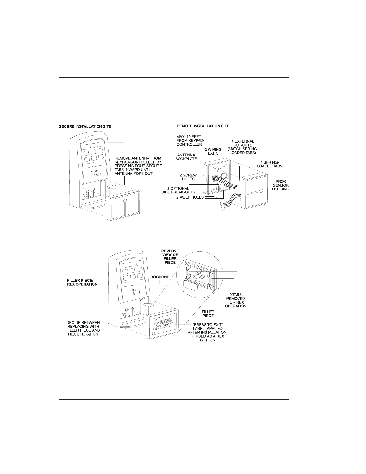
2.4.3 Performing a
Secure Installation
In this configuration, the prox.pad plus prox sensor
housing is removed from the keypad/controller and
located a maximum of 10 feet away. The controller/keypad is located inside a secure area.
1. Remove the antenna from the prox.pad plus keypad/controller as described below:
• Disconnect the backplate of the prox.pad plus unit
from the front keypad/controller.
• When handling the main printed circuit board, to
guard against possible static discharges, touch a
grounded object BEFORE touching the prox.pad
plus unit. Remove the main printed circuit board
by pressing the two spring tabs in the direction of
the arrows as shown in Figure 2-5. Be careful with
the wires.
• Pull on the main circuit board and remove Pin
connector P4 (a 4-pin connector) from the bottom
of the main board. A ribbon cable now holds the
main board to the keypad board. DO NOT pull
this ribbon cable out of its connector! Once the
main board is removed, you can access the interior
of the antenna.
• Remove the antenna housing from the key-
pad/controller by pressing the labeled four secure
tabs inward (see Figure 2-5) until the sensor housing “pops out.”
2. Prepare the wiring and extension wiring as follows:
• Cut off the plastic end of the prox.pad plus sensor
housing harness.
• Splice the recommended remote antenna cable
Alpha 1174C (22AWG), 10-foot maximum length,
to the properly cut antenna cable using standard
electrical techniques.
prox.pad plus Install/Program. Manual, PPP, D2 2-11
Page 28
Chapter 2: Installation 2.4 Mounting the prox.pad plus Unit
KEYPAD/
CONTROLLER
Figure 2-5 Performing a Secure Installation
2-12 prox.pad plus Install/Program. Manual, PPP, D 2
Page 29

2.4 Mounting the prox.pad plus Unit Chapter 2: Installation
3. Mount the antenna backplate in a vertical orientation and secure it to the wall through the two
screw holes using two IEI-provided screws. Ensure that the two “weep holes,” provided to remove possible moisture, are positioned on the
bottom. The wiring exits in the antenna backplate.
(Four external cut-outs on the antenna backplate
match the four spring-loaded tabs on the antenna.)
NOTE: Two side cut-outs are furnished on the
antenna backplate for the wiring, if the installation
does not permit the wiring to run through the
wall.Thesemustbe“cutout”tobeused.
• Once the antenna backplate is mounted properly,
align the antenna to the backplate and connect
the antenna to the antenna backplate. The large
tab in the center of the antenna assembly must be
broken off before being attached to the antenna
backplate.
4. Run the antenna wiring back to the secure keypad/controller and connect it to the main circuit
board, using the 10-inch4-wireharness(red,
black, white, and white) that you plug into connector P4 on the controller board. Connect the red
wire of the antenna to the red wire of the P4
harness, etc. Seal the wire holes with silicone.
5. Select “Filler” or “Request to Exit” (REX) operation
as follows:
• If you elect to use the filler piece as a REX switch,
return to the keypad/controller and break off two
tabs on the filler piece as illustrated in Figure 2-5.
The filler piece replaces the antenna on the front
of the keypad/controller for secure installations.
• If the filler piece is not to be used as a REX switch,
DO NOT remove the two tabs.
prox.pad plus Install/Program. Manual, PPP, D2 2-13
Page 30

Chapter 2: Installation 2.4 Mounting the prox.pad plus Unit
• Select “Filler or “REX” operation and affix the
appropriate IEI-provided label to the filler piece.
For Filler operation, no tabs are brok en off the
filler piece, which merely sits in place of the remotely located antenna, once the main circuit
board and cabling are replaced.
For REX operation, break off the labeled tabs,
which allows a spring-loaded tab to engage the
REX switch on the main circuit board and open
the door.
• Replace the main circuit board into the key-
pad/controller and Pin connector P4 to the main
circuit board.
• Connect the front keypad/controller of the unit to
the back housing.
• Secure with a hex socket screw using the supplied
hex wrench, or secure with a tamper screw
(optional tool required).
2-14 prox.pad plus Install/Program. Manual, PPP, D 2
Page 31

2.5 Inserting Circuit Boards Chapter 2: Installation
2.5 Inserting
Circuit Boards
If it proves necessary to remove or insert the main
circuit board from/into the prox.pad plus controller/keypad, follow the steps below.
1. Disconnect the back housing of the prox.pad plus
unit from the front keypad/controller.
2. (When handling the main printed circuit board,
to guard against possible static discharges, hold
the board by its edges with one hand and then
touch a grounded object BEFORE touching the
prox.pad plus unit.) Remove the main printed
circuit board by pressing the two spring tabs in
the direction of the arrows as shown in Figure 2-6.
Be careful with the wires.
Figure 2-6 Removing/Inserting Printed Circuit
Board
prox.pad plus Install/Program. Manual, PPP, D2 2-15
Page 32

Chapter 2: Installation 2.6 Defaulting prox.pad plus Memory
3. Fold up the main circuit board and remove the P4
connector (a 4-conductor harness) from the bottom of the board.
4. To re-insert, replace the main circuit board into
the keypad/controller and the P4 connector to the
main circuit board.
5. Connect the keypad/controller to the back housing.
2.6 Defaulting
prox.pad plus
Memory
If necessary, the prox.pad plus main memory can be
defaulted. This procedure explains how to do this; see
Figure 2-7 on the next page. You would default the
memory, if, for instance, static discharges have corrupted the prox.pad plus unit, during shipping or installation. You can also do this if you have simply
forgotten the Master Code and you need to enter program mode.
With the power ON, remove the case from the
prox.pad plus front controller/keypad to access the
main circuit board. (For a visual reference of the main
printed circuit board and the related pin connectors,
see Figure 2-2. Table 2-2 describes these pins in detail.)
(When handling the main printed circuit board, to
guard against possible static discharges, touch a
grounded object BEFORE touching the prox.pad plus
unit.)
1. With the power ON, press and hold the Program
button (located on the rear side of the main printed
circuit board) for two seconds.
The yellow LED flashes slowly.
2-16 prox.pad plus Install/Program. Manual, PPP, D 2
Page 33

FORGET MASTER CODE
HOUSING
2.6 Defaulting prox.pad plus Memory Chapter 2: Installation
PCB
MASTER
CODE
SWITCH
(PROGRAM
SWITCH)
(ON REAR SIDE
OF PC BOARD)
CONTROLLER
Figure 2-7 Program Button Location on Main
Circuit Board
prox.pad plus Install/Program. Manual, PPP, D2 2-17
3. Enter the following on the keypad:
46 # 00000 # 00000 # **
The yellow LED flickers for 10 seconds and then
blinks slowly.
4. Once the memory set-up is complete, re-assemble
the unit.
NOTE: CONNECTING DOOR LOOP IN-
PUTBefore powering up the prox.pad plus unit,
connect the Door Loops input to the “Loop Common.” This prevents “Forced Door” or “Propped
Door” conditions from developing upon power-up.
Page 34

Page 35

Chapter 3: Wiring
Chapter 3 provides wiring diagrams and associated
procedures.
3.1 Wiring the
prox.pad plus Unit
3.1.1 Wiring the AUX
Relay for Use as
Alarm Shunt
Select one of these three wiring options, Alarm Shunt,
Forced Door, or Propped Door, depending on how
theprox.padplusunit’sAUXrelayistobeemployed
for this installation (refer to Chapter 4 for programming information). Then refer to sections 3.1.1- 3.1.3
as appropriate.
The Alarm Shunt Relay function may be necessary
when a separate existing security system is in place.
The Alarm Shunt Relay keeps an alarm panel zone
from going into alarm when the door is opened, after
a valid code is entered. The Alarm Shunt function is
assigned to the Aux relay by default. To incorporate
this feature, follow the steps below; see Figure 3-1.
3.1.1.A Wiring the Alarm Shunt Relay
1. Turn OFF power to the prox.pad plus unit, and
then unlatch the keypad from the plastic housing.
2. Locate connector P2 (the 6-pin connector) on the
main circuit board and plug on the 6-pin harness.
(The 2-pin jumper on pins 5 and 6 of connector
P2 must be removed first.)
3. Connect the 6-conductor harness to connector P2
as shown in Figure 2-1.
4. Connect the blue wire to the “Common” side of
the door contact.
5. Connect the green wire to the “Normally Open”
side of the door contact.
6. Make a parallel connection to the green and blue
wires and run the leads to the alarm panel. NOTE:
This feature requires that you use the “Door Contact”inputasshowninFigure3-1.
prox.pad plus Install/Program. Manual, PPP, D2 3-1
Page 36

D
C
G
T
P
R
it
Chapter 3: Wiring 3.1 Wiring the prox.pad plus Unit
TO ALARM PANEL
OOR
ONTACT
OING BACK
O ALARM
ANEL
BLUE ( C )
TO ALARM PANEL
GREEN
(N/O)
P5
ORANGE
SEPARATE DOO
CONTACT BEING
MONITORED BY
THE prox.pad un
WHITE
Figure 3-1 Wiring the Aux Relay
for Alarm Shunt Operation
3-2 prox.pad plus Install/Program. Manual, PPP, D2
Page 37

3.1 Wiring the prox.pad plus Unit Chapter 3: Wiring
3.1.2 Wiring the AUX
Relay for Use as
Forced Door
The Forced Door output function informs personnel
that the door has been opened without authorization.
By default, the Forced Door output is assigned to
Audio Alert #1. To use the Aux Relay, you must first
assign it. See the command below, in the second note.
The Aux relay is rated to handle two amps of current
at 12 VDC, and can turn ON or OFF one leg of the
power to a warning device. (Warning device not included with the IEI unit.) To incorporate this feature,
followthestepsbelow;seeFigure3-2.
3.1.2.A Wiring the Forced Door Relay
1. Turn OFF power to the prox.pad plus unit, and
then unlatch the keypad from the plastic housing.
2. Locate connector P2 (the 6-pin connector) on the
main circuit board.
3. Connect the 6-conductor harness to connector P2.
(The 2-pin jumper on pins 5 and 6 of connector
P2 must be removed first.)
4. Connect the green wire (NO) to V+ on the warning device.
5. Connectthebluewire(C)toV+onthepower
supply.
6. Connect V- from the power supply to V- on the
sounder. The gray wire is not used.
NOTE: To use the default 10-second Forced Door
Relay time, no programming is necessary. To
change this default (from 10 to 990 seconds), use
command 45 # ttt # 0 # ** after the unit is installed
successfully; for details, see section 4.3.4.
NOTE: PROGRAMMING FOR FORCED DOOR:
To assign the Forced Door output to the Aux Relay,
enter the following on the keypad:
10#4#2#**
To disable audio alert #1, enter:
10#0#5#**
prox.pad plus Install/Program. Manual, PPP, D2 3-3
Page 38

D
C
G
T
P
R
it
Chapter 3: Wiring 3.1 Wiring the prox.pad plus Unit
TO ALARM PANEL
OOR
ONTACT
OING BACK
O ALARM
ANEL
BLUE ( C )
TO ALARM PANEL
GREEN
(N/O)
P5
ORANGE
SEPARATE DOO
CONTACT BEING
MONITORED BY
THE prox.pad un
WHITE
Figure 3-2 Wiring the Aux Relay
for Forced Door Alarm
3-4 prox.pad plus Install/Program. Manual, PPP, D2
Page 39

3.1 Wiring the prox.pad plus Unit Chapter 3: Wiring
3.1.3 Wiring the AUX
Relay for Use as
Propped Door
The Propped Door Relay output function informs personnel that the door is being held open, or “propped”
open, after a valid entry. By default, the Propped Door
output is assigned to audio alert #2. To use the Aux
Relay, you must first assign it. See command below.
The Aux relay is rated to handle two amps of current
at 12 VDC, and turns ON or OFF one leg of the power
to a warning device. (Warning device not included
with the IEI unit.) To incorporate this feature, follow
thestepsbelow;seeFigure3-3.
3.1.3.A Wiring the Propped Door Relay
1. Turn OFF power to the prox.pad plus unit, and
then unlatch the keypad from the plastic housing.
2. Locate connector P2 (the 6-pin connector) on the
main circuit board.
3. Connect the 6-conductor harness to connector P2.
(The 2-pin jumper on pins 5 and 6 of connector
P2 must be removed first.)
4. Connect the green wire (NO) to V+ on the
sounder.
5. Connectthebluewire(C)toV+onthepower
supply.
6. Connect V- from the power supply to V- on the
sounder. The gray wire is not used.
NOTE: To use the default 30-second Propped Door
Relay time, no programming is necessary. To
change this default (from 30 to 990 seconds), use
command 44 # ttt # 0 ** after the unit is installed
successfully; for details, see section 4.3.3.
NOTE: PROGRAMMING FOR PROPPED DOOR:
To assign the Propped Door output to the Aux
Relay, enter the following on the keypad:
10#3#2#**
To disable audio alert #2, enter:
10#0#6#**
prox.pad plus Install/Program. Manual, PPP, D2 3-5
Page 40

R
it
Chapter 3: Wiring 3.1 Wiring the prox.pad plus Unit
TO POWER SUPPLY
GREEN
(N/O)
P5
V-
V+
V+
BLUE
( C )
ORANGE
SEPARATE DOO
CONTACT BEING
MONITORED BY
THE prox.pad un
WHITE
Figure 3-3 Wiring the Aux Relay
forProppedDoorAlarm
3-6 prox.pad plus Install/Program. Manual, PPP, D2
Page 41

3.1 Wiring the prox.pad plus Unit Chapter 3: Wiring
3.1.4 Wiring the Door
Contact Input
To solve the problem of people “tailgating” in behind
personnel using valid access p rotocol, the Auto ReLock feature is provided. With Auto Re-Lock, a long
door open time can be programmed. Auto Re-Lock
overrides the lock output timer, resetting the door
open time as soon as the prox.pad plus unit senses
that the door is open. A long door open time allows
people sufficient time to carry packages from the proximity reader/keypad to the door and open it before the
timer runs out.
No programming is required to implement this feature.
After a valid access or egress, the prox.pad plus unit
senses that the door switch is open and drops the main
relay immediately. This disengages the lock, which
locks behind the person regardless of how long it takes
that person to get through the door.
NOTE: This feature requires that you use the “Door
Contact” input as shown in Figure 3-4.
prox.pad plus Install/Program. Manual, PPP, D2 3-7
Page 42

Chapter 3: Wiring 3.1 Wiring the prox.pad plus Unit
P5
Figure 3-4 Wiring the Door Contact Input
3-8 prox.pad plus Install/Program. Manual, PPP, D2
Page 43

3.1 Wiring the prox.pad plus Unit Chapter 3: Wiring
3.1.5 Wiring the REX
Switch (Request to
Exit)
The prox.pad plus unit can be wired to monitor a
remote switching device, which is intended to be installed on the “secure” side of a door. The Request to
Exit (REX) switch is a momentary input closure that
engages the lock output for the same length of time
for which it is programmed. This feature can be stored
in the Transaction Log for viewing.
If you elect to perform a secure installation where the
controller is mounted on the secure side of the door,
you can use the filler piece as a REX switch. To enable
the internal REX switch, enter the following programing command: 30#7#1#**
For other installations, a separate REX switch must be
purchased.
Other REX devices can be used to include a remote
button placed at a receptionist’s desk, a press-to-exit
switch on the inside of a door, or a passive infrared
detector, allowing free and convenient egress. The
external REX feature requires no programming; simply
wire the unit as illustrated in Figure 3-5. To incorporate
this feature, follow the steps below:
1. Turn OFF power to the prox.pad plus unit, and
then unlatch the keypad from the plastic housing.
2. Locate connector P2 on the main circuit board.
3. Plug the 6-conductor harness into connector P2.
(The 2-pin jumper on pins 5 and 6 of connector
P2 must be removed first.)
4. If you do not wish to install the door contacts per
Figure 3-5, twist the white wire and the orange
wires together; this is mandatory. If this is not
done, the REX input will not function.
NOTE: The door contact MUST be closed for the
REX feature to work properly.
prox.pad plus Install/Program. Manual, PPP, D2 3-9
Page 44

Chapter 3: Wiring 3.1 Wiring the prox.pad plus Unit
P5
P5
Figure 3-5 Wiring the REX Switch
3-10 prox.pad plus Install/Program. Manual, PPP, D 2
Page 45

3.1 Wiring the prox.pad plus Unit Chapter 3: Wiring
3.1.6 Wiring the Main
Relay
The door lock is wired to connector P1 on the prox.pad
plus main circuit board. Wiring for this 5-pin connector
is described in Table 2-2, Figure 3-6 provides an Electric
Strike (Fail Secure) wiring diagram, Figure 3-7 a
MagLock (Fail Safe) wiring diagram. Refer to the
power supply recommendations in Table 1-1 if necessary.
P5
Figure 3-6 Electric Strike (Fail Secure) Wiring
Diagram
prox.pad plus Install/Program. Manual, PPP, D2 3-11
Page 46

)
(
Chapter 3: Wiring 3.1 Wiring the prox.pad plus Unit
MAGLOCK
(FAIL SAFE)
V-
POWER
V+
SUPPLY
BLACK
(V-)
BLUE
(MAIN RELAY C
GRAY
MAIN RELAY N/C)
RED
(V + IN)
P1
P3
P2
P5
P4
Figure 3-7 MagLock (Fail Safe) Wiring Diagram
3-12 prox.pad plus Install/Program. Manual, PPP, D 2
Page 47

3.2 prox.pad plus Commu nications Chapter 3: Wiring
3.2 prox.pad plus
Communications
NOTE: The Terminator wire
may not be required.
2-Brown (Data A)
3-White (Data B)
4-Green (Data GND)
The prox.pad plus is equipped with RS-485 communications with a data rate of 19200 bits/sec. This allows
you to connect the unit to a personal computer (PC)
either via the computer’s COM (serial) port or over a
computer network to manage the system using Hub
Manager Professional (version 5 or higher) software.
To connect the prox.pad plus unit to a computer COM
port (which is RS-232), an RS-232 to RS-485 converter
is required. To connect the prox.pad plus unit via a
computer network, the IEI Gateway device is required.
The maximum distance from the RS-485 device is
4,000 feet using the specified cable.NOTE:TheTer-
minator wire may not be required. Figures 3-8 and 3-9
show examples of both connection types. Please see
the instructions for your RS-232 to RS-485 converter
or the instructions for the IEI Gateway for details about
those devices. For details, refer to EIA RS-485 specifications.
P1
P3
P2
RS-232 RS-485
To PC
COM port
P5
ó
RS-232 to RS-485
Converter
P4
Figure 3-8 Connecting the prox.pad plus
to a PC COM Port
prox.pad plus Install/Program. Manual, PPP, D2 3-13
Page 48

T
N
Chapter 3: Wiring 3.3 Networking Multiple prox.pad plus Units Together
2-Brown (Data A)
o Computer
etwork
3-White (Data B)
4-Green (Data GND)
RS-485
ó
Gateway
P5
P1
P3
P2
P4
Figure 3-9 Connecting the prox.pad plus to a
Network
3.3 Networking
Multiple prox.pad
plus Units Together
3-14 prox.pad plus Install/Program. Manual, PPP, D 2
For multiple door applications, the prox.pad plus can
be networked together. When networking prox.pad
plus devices together on an RS-485 system, the
prox.pad plus units are all wired in parallel. This networking capability is available when connecting directly to your personal computer’s COM port or when
communicating over a computer network with the IEI
Gateway. Figure 3-10 shows an example of networking
multiple units together. The maximum number of de-
vicesonanetworkis32.
Page 49

Device #1
3.3 Networking Multiple prox.pad plus Units Together Chapter 3: Wiring
NOTE: The maximum
number of devices on a
single network is 32.
P1
P3
P2
Door #1
P5
2-White (DataA)
3-Brown (Data B)
4-Blue (Data GND)
RS-232 to RS-485
Converter or IEI
Gateway
P4
Device #2
P1
P3
P2
P5
P4
Door #2
Figure 3-10 Networking Multiple prox.pad plus
Units Together
prox.pad plus Install/Program. Manual, PPP, D2 3-15
Page 50

Chapter 3: Wiring 3.4 Testing the prox.pad plus
3.4 Testing the
prox.pad plus
3.4.1 Testing the
Controller/Keypad
At this point in a typical installation, it is assumed that
the prox.pad plus unit has been mounted and wired
successfully as described earlier and that testing can
begin. IEI recommends, however, that first-time in-
stallers test the prox.pad plus unit BEFORE actually
mounting and wiringthe unit to become familiar with
its operation.
1. Connect the positive (+) lead of the power supply
to the V+ input on the prox.pad plus controller/keypad.
2. Connect the negative (-) lead of the power supply
to the V- input on the prox.pad plus controller/keypad.
3. Turn ON the power supply.
4. Ensure that the bi-color LED (red and green) on
the prox.pad plus unit lights red.
5. On the prox.pad plus controller/keypad, press:
7890 # 123456 *
If all 12 key presses are verified, the prox.pad plus
unit enters the self-test mode. The bi-color LED
turns green. The red LED blinks alternately with
theyellowLEDandthenbothturnOFF.Next,
the sounder beeps three times, pauses, and then
beeps once more. If this does not occur, attempt
to enter the self-test mode again by repeating step
5.
NOTE: If you are using the IEI DCD software, you
can capture the self-test data on a PDA. This data
contains information about the device.
6. Enter the master code on the keypad by pressing:
1234 *
The red LED turns OFF and the green LED turns
ON for five seconds while the main relay energizes. To program the unit, see Chapter 4.
3-16 prox.pad plus Install/Program. Manual, PPP, D 2
Page 51

Chapter 4:
Programming
4.1 Programming
Overview
4.1.1 Programming
from the Keypad
Chapter 4 provides information about programming
the IEI prox.pad plus unit.
The first step in programming the prox.pad plus unit
is to place it into Program mode. You can enter Program mode with either the Master code or the Supervisor code. When the prox.pad unit is in Program
mode, the yellow LED blinks slowly; when the yellow
LED stops blinking and is OFF completely, the unit is
no longer in Program mode. If an error is made in
Program mode, the yellow LED remains steadily
lighted; press * to clear the error condition and then
re-enter the command. If the unit does not go into
Program mode, refer to the Troubleshooting Chart in
Chapter 5.
4.1.1.A Master Code (User #1)
TheMastercodeisaspecialcodestoredinuserlocation
one. This code is used to enter Program mode, and
has access to all programming commands.
To place theprox.pad plus unit in Program mode using
the Master code, press:
99 # Master Code *
NOTE: “1234” is the default Master code, which IEI
recommends that you change right away.
To change the Master code, enter:
1 # new master code * new master code *
(example, 1 # 4321 * 4321 *)
NOTE: Codes can be from 1 to 6 digits in length.
prox.pad plus Install/Program. Manual, PPP, D2 4-1
Page 52

Chapter 4: Programming 4.1 Programming Overview
4.1.1.B S upervisor Code (user #2)
The Supervisor code is a special code stored in user
location two. This code has limited access to Program
mode, including commands:
• Adding/Deleting Users (commands #50, #51,
#52, #53, #57, and #58)
• Enabling/Disabling Users (command #56)
• Changing Lock Output Time (command #11)
• Changing Keypad Platform Parameters 5 and 6
(command #32)
By default, user location two is empty, which means
that if you need a Supervisor code, you must program
one. To program a Supervisor code, press:
2 # new supervisor code *
new supervisor code *
(example, 2 # 5678 * 5678 *)
To enter Program mode using the Supervisor code,
press:
99 # supervisor code *
4.1.1.C Master Code and Supervisor Code
Special Features
The following is list of items that pertain only to the
Master and Supervisor codes:
• The Master and Supervisor codes can only be pro-
grammed as standard user types
• The Master and Supervisor codes can be pro-
grammed as “card AND code” or “card OR code”
users.
• The Master and Supervisor codes cannot be pro-
grammed as “card only.”
4-2 prox.pad plus Install/Program. Manual, PPP, D2
Page 53

4.1 Programming Overview Chapter 4: Programming
• When either the Master or Supervisor is pro-
grammed as “card AND code,” both are required
to enter Program mode.
• When they are programmed for “card OR code,”
only the card is required to enter Program mode.
• IftheMasterorSupervisorisprogrammedfor
“card OR code” and you want them to require
both to enter Program mode, enable option 3 using
command30(30#3#1#**).
4.1.1.D prox.pad plus Default Settings
Table 4-1 lists the default settings for the prox.pad plus
unit as shipped from the factory. Subsequent sections
in this chapter explain how to change these default
settings or program additional functions.
Table 4-1. prox.pad plus Default Settings
Parameter Default Setting
Main Relay Lock Output
Auxiliary Relay Alarm shunt function
Audio Alert #1 Forced Door
Audio Alert #2 Propped Door
Master Code (user one) 1234*
Main Relay energizes for Five (5) seconds
Audible Keypress Feedback ON
Propped Door Output activates after Thirty (30) seconds
Forced Door Output activates for Ten (10) seconds
prox.pad plus Install/Program. Manual, PPP, D2 4-3
Page 54

Chapter 4: Programming 4.1 Programming Overview
Table 4-2. prox.pad plus LED Indicators/Sounder Operations
LED or Sounder Visual/Audible
Condition
Yellow LED Slow blink Unit is in Program mode
Rapid blink Verify mode is active (checking that the
Steady Program error; to clear, press * or error
Very rapid blink Memory (eeprom) erase is in progress
Bi-color LED Steady red Lock output deenergized
Steady green Lock output is energized (timed or
Red/green
alternating
Green blink Auto-unlock active
Sounder Short beep
(100 ms) every 2
seconds
Sounder 1/2 sec
on, 1/2 sec off
Description
last two values in sequence match)
lockout
(commands 40/46, loop-back)
latched)
Awaiting second PIN during “Card AND
Code” access attempt
Audio alert #2 is active
Audio alert #1 is active
Double beep Lockout is canceled
Pair of double
beeps
3 slow beeps
(250 ms), then
single beep
4-4 prox.pad plus Install/Program. Manual, PPP, D2
Lockout is activated
Self-test is complete
Page 55

4.1 Programming Overview Chapter 4: Programming
Table 4-2. prox.pad plus LED Indicators/
Sounder Operations (continued)
Sounder After
PIN/Card
1 single beep Valid card access
1longbeep
followed by 1
short beep
1longbeep
followed by 2
short beeps
1longbeep
followed by 3
short beeps
3 rapid beeps
after code entered
or card presented
4 quick beeps First-In Auto-unlock
6 quick beeps Toggle mode is active
User disabled
Bad timezone
User lockout
Code or Card is not found
4.1.1.E Resetting the Master Code and System
Defaults Only
Entering command 40 erases everything from the
prox.pad plus memory except the user list and transaction log and restores the default settings. This is
useful if the prox.pad plus unit has experienced programming problems, or you wish to delete earlier programming.
1. Place the prox.pad plus unit in Program mode.
Press:
99 # Master Code * (default is 1234)
A slow blinking yellow LED indicates that the unit is
in Program mode. A steady yellow LED, in contrast,
means that errors were d etected during programming.
prox.pad plus Install/Program. Manual, PPP, D2 4-5
Page 56

Chapter 4: Programming 4.1 Programming Overview
Error states can be cleared by pressing the asterisk *
key.
2. Press:
40 # 00000 # 00000 # **
The yellow LED continues to blink slowly.
3. Press * to exit Program mode.
4.1.1.F Erasing Entire Memory/Resetting System
Defaults
Entering command 46 deletes everything from the
prox.pad plus memory including the user list but not
the transaction log and restores the default settings.
This is used as a last resort if you need to erase a specific
user and could not retrieve the Programmed User List.
1. Place the prox.pad plus unit in Program mode.
Press:
99 # Master Code * (default is 1234)
A slow blinking yellow LED indicates that the unit
is in Program mode. A steady yellow LED, in
contrast, means that errors were detected during
programming. Error states can be cleared by pressing the asterisk * key.
2. Press:
46 # 00000 # 00000 # **
The yellow LED continues to blink slowly.
3. Press * to exit Program mode.
4-6 prox.pad plus Install/Program. Manual, PPP, D2
Page 57

4.2 Programming Users Chapter 4: Programming
4.2 Programming
Users
4.2.1 Adding New or
Changing Existing
Codes/Cards
The most basic prox.pad plus programming is adding
new codes or cards (users), or modifying existing codes
or cards (users). Each user entry consists of three or
four data values: a user type, a location and a keypadPIN, and/or card.
Two methods can be used for adding new or c hanging
existing codes/cards, (1) keypress sequences (manual
entry), and (2) card presentations. Keypad PINs can
be programmed only through a keyp a d sequence,
while card PINs can be programmed manually or by
presenting the card to the proximity reader at a specified time during programming.
Table 4-3 lists the specific types of users that can be
programmed with the prox.pad plus unit and the following section describe the various ways to program
users.
NOTE: When 26-bit cards are used and you choose to
add new cards manually, the facility code MUST be
entered into the unit first. The default facility code is
11. For the programming sequence used to enter the
3-digit facility code, see command 32, parameter 4 (see
table in section 4.6).
4.2.2 Programming
Code and Card
The prox.pad plus unit can be programmed to accept
the four code/card combinations listed below.
Options
• (1) Code ONLY (command 50)
• (2) Code AND Card (command 50 plus present
card to proximity reader)
• (3) Card ONLY (command 50 or command 51)
• (4) Code OR Card (command 52)
NOTE: No user can have the same card and/or
code PIN as another user.
prox.pad plus Install/Program. Manual, PPP, D2 4-7
Page 58

Chapter 4: Programming 4.2 Programming Users
4.2.2 Programming
User Types
Table 4-3 identifies and describes the user types supported by the prox.pad plus unit.
Table 4-3. prox.pad plus User Types
User Type Numeric ID Description
Toggle users latch the lock in the unlock
Toggle 0
Standard 1
Log Dump 2
Lockout 3
Extended Unlock 4
Single Use Code 5
position.Togglemodeisindicatedby6
quick beeps and a solid green LED.
Standard users use the lock duration
programmed in command 11.
For this user-type, the door remains locked
and the Transaction Log is dumped to the
DCD PDA software through the IR LED
when the appropriate code is entered. This
code cannot be used to gain access
through the door. The log is not erased,
only printed.
Lockout users “lock out” other users - see
User Lockout (section 4.4.1). These codes
do not unlock the door.
Extended Unlock Users are like Standard
users except they use the unlock duration
programmed in command 32, parameter 3.
The default unlock time is 10 seconds.
Single Use Codes are codes that can only
be used once. After the code is used, it is
deleted from the keypad. To verify a Single
Use is programmed, enter the sequence
[5# PIN *] and this looks up the PIN and
generates a 1/2 second green flash if the
PIN is programmed as a single use code. If
the PIN is not found, the system generates
three quick beeps and increments the
invalid PIN counter. If PIN is found but is
not programmed as a single use code, the
system does not respond at all.
4-8 prox.pad plus Install/Program. Manual, PPP, D2
Page 59

4.2 Programming Users Chapter 4: Programming
Table 4-3. prox.pad plus User Types (continued)
User Type Numeric ID Description
Relock codes are used to relock the door
when a toggle or auto-unlock is active.
Relock 6
Emergency 7
4.2.2.A Programming User Data, Command 50,
Full Format
The full format of command 50 for programming user
data is as follows:
Entering 00 # prior to a relock code allows
auto-unlock to be re-triggered, when First In
is enabled.
Emergency users are special users that
cannot be locked out and cannot be
disabled.
The user also uses the unlock duration
programmed in command 32 parameter 3.
The default unlock time is 10 seconds.
50 # user-type # user location # keypad
PIN*keypadPIN*
Programming a user’s card with command 50 requires
that you present the card to the proximity reader after
entering the final asterisk *.
A single beep from the sounder indicates that the card
has been read and the data added to the user’s entry.
If the yellow LED lights steadily after the card is presented, it usually indicates one of two problems: (1)
an improper keypress (correct by entering properly),
or (2) the number entered is in use by another user
(correct by employing an unused PIN and card).
prox.pad plus Install/Program. Manual, PPP, D2 4-9
Page 60

Chapter 4: Programming 4.2 Programming Users
4.2.2.B Quick Program Feature
A “quick program” feature has been implemented for
user data, however. You only need to enter the user’s
location and the keypad PIN (or present card), in the
format noted below. Employing the quick feature automatically selects a “Normal” user access type.
loc#PIN*PIN*
OR
loc # ** <present card>
4.2.2.C Programming Code ONLY Use
You can program a user Code ONLY use with command 50. The program sequence is as follows:
50 # user-type # user location # keypad
PIN * keypad PIN *
4.2.2.D Programming Code AND Card Use
The format for programming a user for both Code
AND Card use is as follows:
50 # user-type # user location # keypad
PIN * keypad PIN * <present card>
When a combination code/card user employs the
prox.pad plus unit, that user can present the proximity
cardfirstattheproximityreader,orenterthecode
first at the prox.pad plus keypad as desired.
After the code/card user either presents the card at the
reader or enters the code on the keypad, the red and
green LEDs alternate. This indicates that the unit is
awaiting the second part of the transaction before
granting access. After the secondpart of the transaction
is completed successfully, the bi-color LED turns solid
green and the door opens.
4-10 prox.pad plus Install/Program. Manual, PPP, D 2
Page 61

4.2 Programming Users Chapter 4: Programming
4.2.2.E Programming Card ONLY Use
Card ONLY use can be programmed with command
50. The p rogramming sequence is as follows:
50 # user-type # user location # **
<present card>
4.2.2.F Programming Code OR Card
Finally, you can program a user for either Code OR
Card use as follows:
52 # user-type # user location # keypad
PIN* keypad PIN * <present card>
prox.pad plus Install/Program. Manual, PPP, D2 4-11
Page 62

Chapter 4: Programming 4.2 Programming Users
4.2.3 Batch Load
Cards by Presentation
Command 53 provides a simple method of programming a group of consecutive users by presenting the
appropriate prox cards. This method of programming
cards does not require any knowledge of the prox card
format as long as it contains 39 bits or less of data.
The format of the command is as follows:
53 # user type # start location # * *
present cards one after another
The card loading stops automatically once the current
user location exceeds 2000. Pressing any key on the
faceplate aborts the loading process.
All users programmed through this command are
setup as “Card Only” users. Any existing card or keypad data for that user is erased prior to programming
the new data. Entering the Master or Supervisor user
as the first card in the sequence generates an error
because the Master or Supervisor code cannot be programmedasa“CardOnly”user.
If an existing card is presented, a programming error
is generated. You clear the error condition by pressing
the [*] (asterisk) and continue presenting cards. This
is the only case where pressing a key on the faceplate
does not abort the card programming sequence.
4-12 prox.pad plus Install/Program. Manual, PPP, D 2
Page 63

4.2 Programming Users Chapter 4: Programming
4.2.4
Enabling/Disabling
Users Command
The56#set/clear#userLocation#commandallows
the Master Code or Supervisor Code to disable a particular user location without deleting that user.
To disable a user, enter:
56#1#userlocation#**
To enable a user, enter:
56#0#userlocation#**
• TheMasterCodecanNEVERbedisabled.
• The Master Code can disable the Supervisor user
(user # 2).
• The Supervisor can disable users 3-2000.
The Master Code user cannot be disabled, and the
supervisor user cannot disable his/her self. A disabled
Supervisor cannot access Program mode; a non-programmed user cannot be enabled or disabled (generates a program error).
prox.pad plus Install/Program. Manual, PPP, D2 4-13
Page 64

Chapter 4: Programming 4.2 Programming Users
4.2.5 Batch Load
Cards Manually
(without presentation)
“Batch entry” allows you to enter multiple, sequential
26-bit HID cards into the prox.pad plus unit’s memory
at one time. (Keeping IEI proximity cards in order is
easyasthecodeisprintedonthefrontofeachcard.)
NOTE: The facility code must be programmed into
theunitbeforeanybatchentrycanoccur.Thefacility
code MUST be programmed only once. The default
facility code is 11. For the programming sequence
used to enter the 3-digit facility code, see command
32, parameter 4 (see table in section 4.6).
To add several users from the proximity reader, follow
this procedure:
1. Place the prox.pad plus unit in Program mode.
Press:
99 # Master Code * (default is 1234)
A slow blinking yellow LED indicates that the unit
is in Program mode. A steady yellow LED, in
contrast, means that errors were detected during
programming. Error states can be cleared by pressing the asterisk * key.
2. On the prox.pad plus keypad, press:
57 # (total number of cards to be added) #
(starting user location) # card number *
repeat card number *
NOTE: Never enter one (1) or (2) as the starting user
location since they are reserved for the Master code
and Supervisor code, respectively.
3. On the prox.pad plus keypad, press * to exit Program mode.
Up to 1998 users can be added this way at one
time. (User 1 is reserved for the Master code, User
2fortheSupervisorcode.)
4-14 prox.pad plus Install/Program. Manual, PPP, D 2
Page 65

4.2 Programming Users Chapter 4: Programming
4.2.6 Block Delete of
Users
4.2.7 Deleting Users
Command 58 lets you delete a block of users. To lessen
the chance of accidental deletion, the command sequence requires a double entry of the starting user and
number of users values. If the values entered do not
match, a programming error occurs. The format of the
new command is as follows:
58 # start user # start user # number of
users * number of users *
The yellow led blinks rapidly during the deletion process; it can take several seconds to delete all 2000 users.
To delete a user from the prox.pad plus unit’s memory,
you must know the user location in which the information is stored. Printing a Programmed Users List (as
described in section 4.5) helps you determine this, if
you are using the DCD software. If not, the programmer should have filled out a paper chart listing the
memory location or register in which all users are
stored.
To delete a user, follow the steps below.
1. Place the prox.pad plus unit in Program mode.
Press :
99 # Master Code * (default is 1234)
A slow blinking yellow LED indicates that the unit
is in Program mode. A steady yellow LED, in
contrast, means that errors were detected during
programming. Error states can be cleared by pressing the asterisk * key.
2. On the prox.pad plus keypad, enter the user
number you wish to delete and a pound symbol
#. To delete user 100, for example, press:
100 # ** (to delete user 100)
The yellow LED blinks slowly.
3. Press * to exit Program mode.
prox.pad plus Install/Program. Manual, PPP, D2 4-15
Page 66

Chapter 4: Programming 4.3 Programming Outputs
4.3 Programming
Outputs
4.3.1 Changing the
Lock Output Time
4.3.2 Assigning
Outputs
The factory default main relay time is five (5) seconds.
Main Lock Output time can be set in one-second increments from 1-255 seconds using command 11.
1. Place the prox.pad plus unit in Program mode.
Press:
99 # Master Code * (default is 1234)
A slow blinking yellow LED indicates that the unit
is in Program mode. A steady yellow LED, in
contrast, means that errors were detected during
programming. Error states can be cleared by pressing the asterisk * key.
2. Enter the new Lock Output time, in seconds (from
1 to 255). For example, to enter 10 seconds, press:
11#10#0#**
The yellow LED continues to blink slowly.
3. Press * to exit Program mode.
The prox.pad plus unit is equipped with four virtual
outputs and four physical outputs. The virtual outputs
consist of the Lock Output, Alarm Shunt Function,
Propped Door Output, and Forced Door Output. A
virtual output is simply an output that can be assigned
to a physical output. The physical outputs include the
Main Relay, the Aux Relay, Audio Alert #1, and Audio
Alert #2. The default output assignments are:
• Lock Output is assigned to the Main Relay
• Alarm Shunt Function is assigned to the Aux Relay
• Forced Door Output is assigned to Audio Alert #1
• Propped Door Output is assigned to Audio Alert
#2
4-16 prox.pad plus Install/Program. Manual, PPP, D 2
Page 67

4.3 Programming Outputs Chapter 4: Programming
This feature is useful considering the product only has
two relays; you can assign these relays to any of these
functions. There are only a few things to keep in mind
when assigning the outputs.
• Any virtual output can be assigned to any physical
output.
• A virtual output can be assigned to multiple physi-
cal outputs.
• A physical output can only have one virtual output
assigned to it.
To assign the outputs, use the following command:
10 # virtual output # physical output # **
The chart below shows the output options with the
corresponding value.
Virtual Outputs Physical Outputs
1=Lock 1=MainRelay
2=AlarmShunt 2=AuxRelay
3 = Propped Door 5 = Audio Alert #1
4=ForcedDoor 6=AudioAlert#2
For example, to assign the Forced Door Output to the
Aux Relay, enter the following command in Program
mode:
10#4#2#**
After entering this command, the Forced Door Output
is still assigned to Audio Alert #1. If you do not want
the audio alert to sound for Forced Door, you MUST
disable Audio Alert #1. To disable an output, e nter a
0 for the virtual output. To disable Audio Alert #1 enter
following command:
10#0#5#**
NOTE: The audio alerts use the local keypad
sounder. Audio Alert #1 is indicated by a ½ second
on, ½ second off beeping. Audio Alert #2 is indicated by a short beep every two seconds.
prox.pad plus Install/Program. Manual, PPP, D2 4-17
Page 68

Chapter 4: Programming 4.3 Programming Outputs
4.3.3 Setting Propped
Door Output Time
4.3.4 Setting Forced
Door Output Time
Command #44 lets you set the Propped Door Output
time.
1. Place the prox.pad plus unit in Program mode.
Press:
99 # Master Code * (default is 1234)
A slow blinking yellow LED indicates that the unit
is in Program mode. A steady yellow LED, in
contrast, means that errors were detected during
programming. Error states can be cleared by pressing the asterisk * key.
2. To program the Aux relay for Propped Door, enter
the following on the keypad:
10#3#2#**
3. Enter the desired Propped Door Output time. For
example:
44#ttt#0#**
where, ttt=propped door time, to nearest 10’s
seconds, entered as 10-990; default=30 seconds.
4. Press * to exit Program mode.
Command #45 lets you set the Forced Door Output
time.
1. Place the prox.pad plus unit in Program mode.
Press:
99 # Master Code * (default is 1234)
A slow blinking yellow LED indicates that the unit
is in Program mode. A steady yellow LED, in
contrast, means that errors were detected during
programming. Error states can be cleared by pressing the asterisk * key.
2. To program the Aux relay for Forced Door, enter
the following on the keypad:
10#4#2#**
4-18 prox.pad plus Install/Program. Manual, PPP, D 2
Page 69

4.4 Programming Keypad Options and Parameters Chapter 4: Programming
3. EnterthedesiredForcedDoorOutputtime.For
example:
45#ttt#0#**
where, ttt=forced door time, to nearest 10’s
seconds, entered as 10-990; default=30 seconds.
4. Press * to exit Program mode.
4.4 Programming
Keypad Options
and Parameters
4.4.1 User Lockout
Option
The prox.pad plus unit supports two types of user
lockouts: “Lockout By Location” and “Lockout By
Group.” The two lockouts share the following features:
(1) entering Program mode always clears an active
lockout (2) and neither the “master,” the“ supervisor,”
nor an “emergency” user can be locked o ut. The user
lockout function, which is enabled by default, can be
disabled through Command 30 option#5. The lockout
type is selected through Command 30 option #8 and
defaults to “Lockout By Location.”
4.4.1.A Lockout By Location
In the Lockout By Location mode, the location of the
Lockout Code in the user table determines which users
are locked out. Entering a Lockout Code (when no
lockouts are active) excludes all users programmed in
locations greater than the location of that Lockout
Code. For example, if user #20 is programmed as a
Lockout Code and that user’s PIN is entered, then
users #21 and above are locked out.
Entering the same Lockout Code cancels the current
lockout. If a different Lockout Code (programmed in
a location less than the current lockout) is entered
during an active lockout, the lockout is “lowered” to
the location of that PIN. This means that to cancel a
prox.pad plus Install/Program. Manual, PPP, D2 4-19
Page 70

Chapter 4: Programming 4.4 Programming Keypad Options and Parameters
lockout initiated by another user, the “new” user must
enter his PIN twice. The first entry lowers the lockout
and the second cancels the lowered lockout.
4.4.1.B Lockout By Group
Lockout By Group is an enhanced version of the lockout function. In this mode, each user is assigned to a
lockout “group.” The user lockoutgroupissetwith
command 32 ,parameter 6 and defaults to 4. The group
set in parameter 6 is applied to all newly added users,
and can be changed prior to adding each user if required.
Lockout groups can be from 0 to 15. User lockout group
0 is special because it allows users programmed with
that group to be processed regardless of the current
user lockout state (meaning group 0 users cannot be
locked out). A good example of group 0 usage might
be a Relock Code, which would allow a group 0 user
to re-lock a door even if a user lockout is active. Exercise
care (restraint) when creating group 0 users; if there
are too many, the usefulness of user lockout diminishes.
Entering a Lockout Code (when no lockouts are active)
sets the current lockout group to that user’s lockout
group. Subsequently, whenever a valid PIN is entered,
that user’s lockout group is compared to the currently
active lockout group. It is the result of this test that
determines whether the user is locked out.
Entering any lockout code while a lockout is active
always cancels the current lockout. To activate another
lockout, you must enter the lockout code again.
4-20 prox.pad plus Install/Program. Manual, PPP, D 2
Page 71

4.4 Programming Keypad Options and Parameters Chapter 4: Programming
The prox.pad plus unit firmware can select one of four
different lockout operations. The selection is made by
setting the Lockout By Group “operand” in command
32, parameter 7 to one of the following values:
• 0 = lockout all other groups
• 1=lockoutjustthisgroup
• 2 = lockout higher numbered groups
• 3 = lockout lower numbered groups
When a “lockout just this group” is activated, all users
in that group are locked out with the exception of those
users programmed as Lockout Codes. This allows the
user who initiated the lockout to cancel t he lockout.
4.4.2 TimeZone/
Holiday Features
The prox.pad plus unit currently supports up to eight
(8) timezones. Timezones are disabled by default and
can be enabled with Command 30 option 9. To enable,
enter:
30#9#1#**
Auto-Unlock is also disabled by default and can be
enabled with command 30, option 11. The default
auto-unlock timezone is in location 8 and is 9:00 A.M.
to 5:00 P.M. Monday through Friday. To make this
timezone active as an auto-unlock, you must enable
option 11. To enable, enter:
30#11#1#**
Additionally, you cannot add timezones through the
keypad directly (software is required); however, you
can assign users to timezones and set a timezone as
auto-unlock, after the timezone is added via software.
prox.pad plus Install/Program. Manual, PPP, D2 4-21
Page 72

Chapter 4: Programming 4.4 Programming Keypad Options and Parameters
To program users to a certain timezone, you must first
set the user timezone mask in command 32, parameter
5. Each user added after this parameter is set is assigned to that timezone. If you want to assign users to
several different timezones, you must change parameter5priortoaddingeachuser.
Take care using parameter 5 since it is an 8-bit number,
and each timezone equals a certain bit value as follows:
• TZ1 = 1
• TZ2 = 2
• TZ3 = 4
• TZ4 = 8
• TZ5 = 16
• TZ6 = 32
• TZ7 = 64
• TZ8 = 128
To program a user to multiple timezones, add up the
number of each timezone. For e xample: To add a user
to timezones 1, 2, and 8, enter 131 (1 + 2 + 128 = 131)
in parameter 5. Entering a value of 255 sets the user
to 24 hours, which means you cannot assign a user to
all eight (8) timezones. To set a timezone as auto-unlock, you must set the auto-unlock timezone mask
using command 38. Example:
38 # autz # 1 # **
(autz=auto-unlock timezone (1-8). Entering 1 sets the
timezone as auto-unlock and a 0 clears it.)
4.4.2.A Midnight Crossing TimeZones
The prox.pad plus unit supports “midnight crossing
timezones,” which is always enabled. This means a
timezone can cross the midnight boundary. For example: A timezone can start at 11:00 P.M. and end at 7:00
A.M.
4-22 prox.pad plus Install/Program. Manual, PPP, D 2
Page 73

4.4 Programming Keypad Options and Parameters Chapter 4: Programming
There is another option for allowing timezones to cross
over midnight if the next day is a holiday. For example,
a timezone is set for 6:00 A.M. to 2:00 A.M. MondayFriday and Friday is a holiday. If you enable this option
(command 30, option 10), users can still gain access
after midnight on Friday. If you disable this option,
users do not have access after midnight.
This option is enabled by default, but can be disabled
using command 30, option 10. To disable, enter:
30#10#0#**
Entering 1 instead of 0 enables the option.
4.4.2.B Holidays
The prox.pad plus unit supports up to thirty-two (32)
holidays. Holidays can be single days or block holidays
(one block holiday counts as only one holiday; you can
have up to thirty-two block holidays).
A block holiday is a group of days with a beginning
and end date. This is useful if you want a whole week
to be considered a holiday. A block holiday can be up
to one year long.
4.4.2.C Daylight Savings Time
Daylight savings time is also supported and is enabled
by default. This can be changed using command 30,
option 13. To disable, enter:
30#13#0#**
Entering 1 instead of 0 enables the option.
The prox.pad plus unit currently supports U.S. and
European daylight savings formats, and this can be
changed using command 30 option 15. U.S. is the default value. To specify U.S.A., enter 0, European 1:
30#15#0#**
prox.pad plus Install/Program. Manual, PPP, D2 4-23
Page 74

Chapter 4: Programming 4.4 Programming Keypad Options and Parameters
When set to U.S. format, daylight savings begins on
the first Sunday in April at 2:00 A.M. (turn back one
hour) and ends on the last Sunday in October at 2:00
A.M. (turn back one hour). When set to European
format, daylight savings begins on the last Sunday in
March at 2:00 A.M. (turn back one hour) and ends on
the last Sunday in O ctober at 2:00 A.M. (turn back one
hour).
4.4.2.D Leap Year
The prox.pad plus unit supports leap year; on the
appropriate leap years February 29th is a valid date.
4.4.2.E Time/Date Set
The time is set using command 41 and is in 24-hour
format. The date is set using command 42. NOTE: The
Time/Date is not reset with the default command. To
set the Time, enter:
41 # hhmm # 0 # **
[hhmm=hour and minute (24-hour format)]
To set the Date, enter:
42 # mmddyy # dow # **
[mmddyy=month, day, year
dow=day of week (1=Sunday,
2=Monday, etc.)]
4.4.3 Turning Visual
LED/Keypress
Indicator ON/OFF
This visual LED/keypress indicator lights the visual
LED once for each key press. This feature provides a
visual acknowledgment that a particular k ey was
pressed hard enough for the unit to understand. The
factory-shipped default setting is ON, but it can be
toggled ON and OFF as desired. NOTE: A common
reason to turn this feature OFF is to prevent an unauthorized user from viewing visual feedback produced when an authorized user enters his/her code.
4-24 prox.pad plus Install/Program. Manual, PPP, D 2
Page 75

4.4 Programming Keypad Options and Parameters Chapter 4: Programming
1. Place the prox.pad plus unit in Program mode.
Press:
99 # Master Code * (default is 1234)
A slow blinking yellow LED indicates that the unit
is in Program mode. A steady yellow LED, in
contrast, means that errors were detected during
programming. Error states can be cleared by pressing the asterisk * key.
2. To enable this feature, press:
30#1#1#**
The yellow LED continues to blink slowly.
3. To disable this feature, press:
30#1#0#**
The yellow LED continues to blink slowly.
4. Press * to exit Program mode.
4.4.4 Turning Audio
Keypress Feedback
ON/OFF
The Audio Keypress Feedback command enables the
sounder to beep once for each key press. This feature
provides an audio acknowledgment that a particular
key was pressed hard enough for the unit to understand. The factory-shipped default setting is ON, but
it can be toggled ON and OFF as desired using command 30. NOTE: Acommonreasontoturnthisfeature
OFF is to prevent an unauthorized user from hearing
the audio feedback emitted when an authorized user
enters his/her code.
1. Place the prox.pad plus unit in Program mode.
Press:
99 # Master Code * (default is 1234)
A slow blinking yellow LED indicates that the unit
is in Program mode. A steady yellow LED, in
contrast, means that errors were detected during
programming. Error states can be cleared by pressing the asterisk * key.
2. To enable this feature, press:
30#0#1#**
prox.pad plus Install/Program. Manual, PPP, D2 4-25
Page 76

Chapter 4: Programming 4.4 Programming Keypad Options and Parameters
The yellow LED continues to blink slowly.
3. To disable this feature, press:
30#0#0#**
The yellow LED continues to blink slowly.
4. Press * to exit Program mode.
4.4.5 Error Lockout
The prox.pad plus controller maintains a count of the
number of consecutive invalid keypad PINs and prox
cards that have been entered. This count is reset by
entering a valid keypad PIN, presenting a programmed prox card, pressing the program button, entering a valid [99 # Master code*] sequence, or by the
expiration of the k eypad timer.
Entering an incorrect Master code in a [99 # Master
Code*] sequence does increment the invalid PIN entry
count. This ensures that attempts to guess the Master
code are not overlooked.
When the invalid entry counter reaches the user-specified level, the error lockout is activated. Error threshold
is programmed through parameter 32 # 0 #, and is
defaulted to three attempts.
Once the error lockout threshold is reached, the keypad is locked out and the yellow LED lights solidly.
This duration defaults to 10 seconds, and is changed
with command 32, parameter 1.
4-26 prox.pad plus Install/Program. Manual, PPP, D 2
Page 77

4.4 Programming Keypad Options and Parameters Chapter 4: Programming
4.4.6 Timed
Anti-Passback
The Timed Anti-Passback function is enabled by default. It lets you specify a length of time that must pass
before the same prox card can be processed after being
presented. The feature is included so that the card
must be outside of the prox read field during the entire
period of time. If the card is reintroduced into the field
prior to expiration of the time delay, the time delay
restarts with a full duration.
Presenting a different card (not necessarily a programmed card) causes the new card data to be processed immediately and also clears the Anti-Passback
timer so that the first card presented now get processed
again immediately.
This feature is selected through option 30 # 16 #; the
duration of the time delay is set through parameter
32 # 8 #. The duration of the time delay can be set
from ½ second to 60 seconds in ¼ second increments.
Disabling the Timed Anti-Passback function provides
another feature that controls how often ANY prox card
is processed. When option 30 # 16 # is disabled, the
value in parameter 32 # 8 # indicates how often a card
will be processed. Please note that the prox read function continues to attempt a card READ every 100 milliseconds, but a valid card read is only PROCESSED
after the specified time delay elapses.
Also note that this function does not require the card
to leave the read field. In fact one of the main uses of
this feature is to adjust the processing rate of cards that
remain in the field. Now you can extend the processing
time to stop this type of unwanted toggling. All that
must be done is to extend the value in com mand
32 #3 #.
prox.pad plus Install/Program. Manual, PPP, D2 4-27
Page 78

Chapter 4: Programming 4.4 Programming Keypad Options and Parameters
Both of these features apply only to prox cards; there
is no “Anti-Passback” processing of keypad PINs.
“Anti-Passback” and the “card process timer” are also
turned off in Program mode.
4-28 prox.pad plus Install/Program. Manual, PPP, D 2
Page 79

4.5 Using the Printing Features Chapter 4: Programming
4.5 Using the
Printing Features
4.5.1 Selecting
Transaction Log
Information
The prox.pad plus unit in conjunction with the optional IEI PDA Data Collection Device (DCD) can captureaTransactionLogandaProgrammedUserList
via the IR port. The Log Dump command is:
70#0#0#**
The User Dump command is:
25#0#0#**
You can selectively progr am specific transaction events
to print or not on the Transaction Log. By “masking”
out certain events, you direct the unit not to save those
events in memory and thus not be available for the
log. The factory default is for all transaction events to
besavedinmemoryandprintedonthelog.Toturn
OFF an event (keep it from being logged), enter:
73#EventCode#0#**
To turn an event ON, enter:
73#EventCode#1#**
Event # Description
1 acess denied - invalid PIN
2programdenied
4REX
5 Propped Door
6 Door Closed
7 Forced Door
16 logdumpedbyuser#N
17 access granted to user #N
19 access denied to user #N, bad timezone
20 toggle mode activated by user #N
(latch set)
21 toggle mode de-activated by user #N
(latch clear)
22 1st in auto-unlock triggered by user #N
23 door relocked by user #N
24 user lockout enabled by user #N
25 user lockout disabled by user #N
26 access denied to user #N - user is
disabled
prox.pad plus Install/Program. Manual, PPP, D2 4-29
Page 80

Chapter 4: Programming 4.5 Using the Printing Features
Event # Description
27 card/code mismatch
29 program mode started by user #N
30 logerasedbyuser#N
32 unprogrammedcarddata
33 unprogrammed code data
50 log retrieved
51 access denied to user #N, user group
lockout
1. Place the prox.pad plus unit in Program mode.
Press:
99 # Master Code * (default is 1234)
A slow blinking yellow LED indicates that the unit
is in Program mode. A steady yellow LED, in
contrast, means that errors were detected during
programming. Error states can be cleared by pressing the asterisk * key.
2. Press:
73#event#0/1#**
“0/1” in the command syntax is the ON/OFF instruction for the unit. Pressing 0 at a certain event
means that that event is not logged and is not
available to be printed. Pressing 1, in contrast,
restores logging and printing for a particular
event. “Event” is a two-digit number that represents a specific transaction as listed on the previous page. A steady yellow LED indicates an
error; if this occurs, start again.
3. Press * to exit Program mode. The yellow LED
stops blinking.
4.5.2 Printing a
Transaction Log
If you have the optional PDA DCD software, you can
capture a Transaction Log on it via the prox.pad plus
IR port. Transaction Logs can be printed using two
different methods, (1) by programming a “dump” code
into memory and (2) by placing the prox.pad plus unit
into Program mode and manually entering the print
Transaction Log command. For details, see the subsections 4.5.2.A and 4.5.2.B on the next page.
4-30 prox.pad plus Install/Program. Manual, PPP, D 2
Page 81

4.5 Using the Printing Features Chapter 4: Programming
4.5.2.A Programming a Transaction Dump Code
1. Place the prox.pad plus unit in Program mode.
Press:
99 # Master Code * (default is 1234)
A slow blinking yellow LED indicates that the unit
is in Program mode. A steady yellow LED, in
contrast, means that errors were detected during
programming. Error states can be cleared by pressing the asterisk * key.
2. For a LOG DUMP USER (Code Only), press:
50#2#userlocation#code*code*
For a CARD DUMP,press:
50#2#userlocation#**<presentcard>
and then present the card at the proximity reader.
(NOTE: A Log Dump User can also be a “card
AND Code” or “Card OR Code” user.)
3. Press * to exit Program mode.
NOTE: Entering the programmed dump code or card
again subsequently causes the unit to send a Transaction Log to the optional PDA DCD program.
4.5.2.B Printing a Transaction Log Manually
1. Place the prox.pad plus unit in Program mode.
Press:
99 # Master Code * (default is 1234)
A slow blinking yellow LED indicates that the unit
is in Program mode. A steady yellow LED, in
contrast, means that errors were detected during
programming. Error states can be cleared by pressing the asterisk * key.
2. Hold the PDA up to the prox.pad plus IR port
steadily (about one or two inches away; the IR
port is located to the right of the yellow LED) and
then press:
70#0#0#**
prox.pad plus Install/Program. Manual, PPP, D2 4-31
Page 82

Chapter 4: Programming 4.5 Using the Printing Features
3. Press * to exit Program mode. The 70 command
is logged in the transaction buffer (in memory),
providing a reference as to when the log was
printed. Refer to the DCD software instructions
for details.
4.5.2.C Erasing a Transaction Log
TheTransactionLogshouldbeerasedfrommemory
after being printed to prevent conflicting logs. To
erase the log, enter the following sequence:
99 # Master Code * 76 # 00000 # 00000 #
**
Then press * to exit Program mode.
4.5.2.D Printing a Programmed Users List
The Programmed Users List showing all user access
information can be printed to the optional PDA software via the unit’s IR port. The Print Programmed
Users List command is 25.
The prox.pad plus unit can store up to 2,000 user IDs
in memory at one time. Each user ID can be a card, a
PIN code, or a combination card/PIN code. User data
is stored in numbered registers, with register one being
known as “user one,” register two “user two,” etc.
User data is stored in the available memory registers
automatically by the unit; you do not have to place
data in any particular order. You can store codes or
cards in the first five registers and skip some registers,
leaving them empty on purpose; you can then continue programming from registers that are out of sequence. This is an important concept since the printed
list identifies the memory register (location) for each
user’s data. It does not print user locations that are not
programmed.
4-32 prox.pad plus Install/Program. Manual, PPP, D 2
Page 83

4.5 Using the Printing Features Chapter 4: Programming
1. Place the prox.pad plus unit in Program mode.
Press:
99 # Master Code * (default is 1234)]
A slow blinking yellow LED indicates that the unit
is in Program mode. A steady yellow LED, in
contrast, means that errors were detected during
programming. Error states can be cleared by pressing the asterisk * key.
2. Hold the PDA up to the prox.pad plus IR port
steadily (about one or two inches away; the IR
port is located to the right of the yellow LED) and
then press:
25#0#0#**
3. When the list is complete, press * to exit Program
mode. Refer to the DCD software instructions for
details.
By default, this command dumps all users, including empty user locations. The user dump select
option (command 30, option 17) lets you change
this. If you enable option 17, only programmed
users are dumped. To enable, p ress:
30#17#1#**
prox.pad plus Install/Program. Manual, PPP, D2 4-33
Page 84

Chapter 4: Programming 4.6 Programming Commands
4.6 Programming
Commands
If you need to change any of the program default
values or wish to add functions, first enter Program
mode and then enter the desired program command.
Defaults are in bold.
Action Desired Press Details
Yellow LED blinks
To enter Program
mode
1. Change Master
Code
Code-only
operation
(example, 4321
Master Code)
2. Assign outputs
3. Set lock output
duration
4. Delete users
99 # (Master Code) *
1 # (new code) * (repeat code) *
1 # 4321 * 4321 *
10 # virtual output # physical output #
**
Virtual Output Physical Output
1 - Lock 1 - Relay 1 (Main)
2 - Alarm Shunt 2 - Relay 2 (Aux)
3 - Propped Door 5 - Audio Alert #1
4 - Forced Door 6 - Audio Alert #2
11 # tt # 0 # * *
user-location # **
slowly (default
Master Code
= 1234)
Entering a zero (0)
for a virtual output
disables the
physical output
tt=numberof
seconds to operate
lock on access (1
through 255)
defaults to 5
seconds
4-34 prox.pad plus Install/Program. Manual, PPP, D 2
Page 85

4.6 Programming Commands Chapter 4: Programming
Action Press Details
5. Set/clear keypad
options
6a. Print
programmed user
list
6b. Print
programmed user
list (starting at a
certain user)
30#0#0#**
Option Set/Clear
0-audio keypress feedback, 0=off, 1=ON
1-visual keypress feedback, 0=off, 1=ON
2-auto entry enable, 0=OFF, 1=on
3-Card and PIN required for 0=OFF,1=on
Program mode
5-user lockout enable 0=off, 1=ON
7-internal REX select 0=OFF,1=on
8-user lockout select 0=BY
LOCATION,
1=by group
9-timezones select 0=OFF,1=on
10-holiday timezone mid- 0=off, 1=ON
night crossing
11-auto-unlock select 0=OFF,1=on
12-first-in auto-unlock 0=OFF,1=on
13-daylight savings time 0=off, 1=ON
select
15-daylight savings time 0=USA,
format 1=European
16-anti-passback 0=off,1=ON
17-user dump select 0=all users
1=programmed
users only
25#0#0#**
25#0#startuser#**
prox.pad plus Install/Program. Manual, PPP, D2 4-35
Page 86

Chapter 4: Programming 4.6 Programming Commands
Action Press Details
7. Change keypad
parameters
8. Set/clear
auto-unlock mask
9. Restore system
defaults (master
user and system
options/parameters
only)
32 # parameter # value # **
Parameter Value
0-error lockout threshold 1-50 (def=3)
1-error lockout duration 1-255 (def=10
sec)
3-extended unlock time 1-255 (def=10
sec)
4-site ID (for cmds 51, 57) 0-255 (def=11)
5-user timezone mask 0-255 (def=255)
(for programming users
through the faceplate)
6-user lockout group 0-15 (def=4)
7-lockout by group 0-3 (def=0)
operand (see below)
0=lockout users in all other
groups
1=lockout users in this
group (except lockout users)
2=lockout users in higher
numbered groups
3=lockout users in lower
numbered groups
8-Anti-Passbackdelay 2-240(1/4sec
increments, def=
4or1sec)
38 # autz # set/clear # * *
40 # 00000 # 00000 # * *
See options below
autz - auto-unlock
timezone (1-8)
Entering a 1 sets
the timezone as
auto-unlock and a 0
clears it
4-36 prox.pad plus Install/Program. Manual, PPP, D 2
Page 87

4.6 Programming Commands Chapter 4: Programming
Action Press Details
10. Set system time
11. Set system date
12. Set door number 43#nnnnn#0#**
13. Set propped
door output time
14. Set forced door
output time
15. Clear eeprom
memory and restore
default settings
41 # hhmm # 0 # **
42#mmddyy#dow#**
44#ttt#0#**
45#ttt#0#**
46 # 00000 # 00000 # **
hhmm=hour/minute,
24-hr format
mmddyy=month,
date, year;
dow=day of week,
1=Sunday, etc.
nnnnn=door
number
Default=0001 (max
number=65535)
ttt=propped door
time, to nearest 10’s
seconds,enteredas
00-990; default=30
secs
entering 00 disables
propped door
ttt=forced door
time, to nearest 10’s
seconds,enteredas
00-990 (00 latches
it); default=10 secs
prox.pad plus Install/Program. Manual, PPP, D2 4-37
Page 88

Chapter 4: Programming 4.6 Programming Commands
Action Press Details
User Types
0 toggle code
1 standard access
2logdump
3 lockout
4 extended lockout
5singleuse
6 relock code
7 emergency
16a. Add code only
user
50 # type # location # key pin *
key pin *
“code only” user
16b.Addcardonly
user by presentation
16c. Add card AND
code user
16d. Delete user
17. Program 26-bit
“card only” user
without presenting
card
18. Program “card
OR code” user
19. Program
consecutive “card
only” users by
presentation
50 # type # location # **
<present card>
50 # type # location # key pin *
key pin * <present card>
50#0#location#**
51 # type # location # card pin *
card pin *
52 # type # location # key pin * key pin
* <present card>
53 # type # start user # **
<present card> <present card> ...
“card only” user by
presentation
“card AND code”
user
delete user
Location MUST
begreater than 2;
Master/Supervisor
cannot be set as
“card only”
Start user MUST be
greater than 2;
Master/Supervisor
cannot be set as
“card only”
4-38 prox.pad plus Install/Program. Manual, PPP, D 2
Page 89

4.6 Programming Commands Chapter 4: Programming
Action Press Details
0 = Enables that
user
1 = Disables that
user;
20. Enable/disable
users
21. Program block
of 26-bit “card only”
users without
presenting cards
22. Delete block of
consecutive users
56 # enable/disable # user # **
57 # number of users # start user #
card pin * card pin *
58 # start user # start user # number of
users * number of users *
Master user cannot
be disabled; an
unprogrammed user
cannot be enabled
or disabled
(generates a
program error)
Start user MUST be
greater than 2;
Master/Supervisor
cannot be set as
“card only”; uses
site ID set in
command 32,
parameter 4
23. Dump
transactions to IR
port
70#0#0#**
This command
MUST be used
while in Program
mode
prox.pad plus Install/Program. Manual, PPP, D2 4-39
Page 90

Chapter 4: Programming 4.6 Programming Commands
Action Press Details
See options below;
24. Set/clear event
log mask
25. Reset (erase)
transaction log
26. To exit Program
mode
73 # event # set/clear # **
Event
1 access denied - invalid PIN
2 program denied
4REX
5 Propped Door
6DoorClosed
7 Forced Door
16 log dumped by user #N
17 access granted to user #N
19 access denied to user #N, bad
timezone
20 toggle mode activated by user #N
(latch set)
21 toggle mode de-activated by user
#N (latch clear)
22 1st in auto-unlock triggered by
user #N
23 door relocked by user #N
24 user lockout enabled by user #N
25 user lockout disabled by user #N
26 access denied to user #N - user is
disabled
27 card/code mismatch
29 program mode started by user #N
30 log erased by user #N
32 unprogrammed card data
33 unprogrammed code data
50 log retrieved
51 access denied to user #N, user
group lockout
76 # 00000 # 00000 # **
* (after final command) Yellow stops flashing
all events are
logged by default
unless stated
otherwise below
Events 30 and 50
cannot be disabled
Events 32 and 33
are disabled by
default
4-40 prox.pad plus Install/Program. Manual, PPP, D 2
Page 91

Chapter 5:
Troubleshooting
Chapter 5 furnishes a Troubleshooting Chart, diagnostic flow charts, a power supply integrity test, and information to correct possible water problems.
5.1 Before Calling
IEI
Whenever your prox.pad plus unit experiences difficulty, before calling IEI for help, first refer to the
Troubleshooting Chart for answers.IftheTrou-
bleshooting Chart does not help, perform the following:
1. Write down the time and date that the problem
occurred, or the time and date when you first
noticed the problem. Also note what the unit was
doing when the problem occurred or was first
noticed.
2. Note all other relevant information, paying particular attention to recent updates, new or inexperienced installers/programmers, or any recent
hardware changes.
3. Attempt to isolate the problem.
4. Refer to the “Troubleshooting Chart” and flow
charts in this chapter. They are designed such that
many common problems can be easily diagnosed
and corrected by users without IEI assistance.
5. Contact your supervisor or the “technical subject
expert” at your facility for assistance for help if
you cannot diagnose and correct the problem
yourself using steps 1-4 above
6. Contact IEI for help only if using steps 1-5 above
fails to resolve the problem. Make sure that you
have a written description of the problem (and
any steps you may have taken attempting to remedy the problem) before calling for help. Write
prox.pad plus Install/Program. Manual, PPP, D2 5-1
Page 92

Chapter 5: Troubleshooting 5.1 Before Calling IEI
down the version number of your prox.pad plus
unit before calling IEI for help.
Table 5-1. Troubleshooting Chart
Problem Probable Cause Solution
Red LED turns green
when access
accepted, but door
does not open
Various: power
supply voltage
problems, locking
device power supply
not set correctly
1. Check power supply voltage.
2. Monitor voltage at unit’s V+
and V- terminals (on P1) with
meter, enter a valid code, and
ensure that voltage remains
constant while locking device
attempts to unlock and relock. If
voltage varies 1/4 volt or more
during this test, this is a problem
you must correct; look for the
following:
-verify that power supply is rated
sufficiently for all equipment
being powered
-verify that locking device, if on
same power supply, is set up for
current being drawn (example: if
a lock draws 300mA at 24VDC,
same lock may draw 600mA at
12VDC, especially if the unit
requires that jumpers be placed
in a different configuration
-place meter across lock power
wires at lock and ensure the lock
is receiving proper voltage
prox.pad plus unit
experiences reduced
read range problems
5-2 prox.pad plus Install/Program. Manual, PPP, D2
Various: unit is
mounted on a metal
surface, or other
equipment
producing RF
interference
For metal surface problems, see
section 2.2.3; for RF interference
problems, see section 2.2.4.
Page 93

5.1 Before Calling IEI Chapter 5: Troubleshooting
Table 5-1. Troubleshooting Chart (continued)
Problem Probable Cause Solution
prox.pad plus unit
not entering
program mode when
99 # Master code *
is pressed on the
prox.pad plus
keypad or
installer/programmer
forgets the “master
code"
Various: master
code has been
changed, is
incorrect, or new
code not
programmed
correctly
1. With power to the prox.pad
plus unit turned ON, remove the
main circuit board from the unit
as described in section 2.5.
2. Locate the “Program” button
(SW1) underneath the main
circuit board and press it for
about 2 seconds. Take care if
you must pull the circuit board
out of the plastic housing. Handle
the board by its edges,
otherwise, your fingers can short
the solder points. Figure 2-7
illustrates the location of this
button. (When handling the
main printed circuit board, to
guard against possible static
discharges, touch a grounded
object BEFORE touching the
prox.pad plus unit.) (The yellow
LED blinks slowly, indicating that
program mode is active.)
3. To program a new master
code, press:
1# new-code * repeat-code *
Thecodecanbe1-6digits,with
repeated numbers acceptable.
4. To exit program mode, press *.
5. Continue programming as
described in Chapter 4.
prox.pad plus Install/Program. Manual, PPP, D2 5-3
Page 94

External Request to Exit Input Not
Chapter 5: Troubleshooting 5.2 Flow Charts
5.2 Flow Charts
Activating prox.pad plus
YES
Perform power integrity test
(section 5.3).
FAIL
Troubleshoot per instructions
in Table 5-1.
1. Disconnect any devices connected to white,
orange, and brown. 2. Short the W and
O wires together and maintain connection. 3.
Momentarily short the O and B/R terminals to
activate the egress input. Does the prox.pad plus
work?
NO
1. Verify that no other equipment is monitoring
same door contacts as prox.pad plus. 2. If so,
disconnect all other devices on that set of
contacts, except the prox.pad plus. 3. Try
again.
Bad
prox.pad
plus
PASS
1. Meter and verify correct prox.pad plus voltage. 2. Reference
prox.pad plus instructions.
NO
1. Resolve issue. 2. Erase prox.pad plus
memory to erase any program glitch.
PASS
1. Verify that door position switch closed before
attempting to engage the REX. (prox.pad plus
ignores this input when door is open.) 2. If no door
contacts are used, jumper input together with a
piece of wire and try again.
Solved! Shut the
FAIL
YES
1. With the door contacts closed, meter continuity
between exit switch and wires from prox.pad plus.
(Meter should read an open and then a closed
circuit when exit device is activated.) 2. Reconnect
exit switch. 3. With door contact input closed, try
the switch again.
1. Verify that exit device is "dry contact"
and no induced voltages, A/C or D/C, are
being applied to input. 2. More than one
volt?
door.
FAIL
PASS
YES
If problem persists,
see Note at bottom.
NO
Locate source and
eliminate. (Circuit requires
a dry switch.)
NOTE: A glitch in the prox.pad plus program might result from using a
power supply that is not filtered and regulated properly. For extra
filtering suggestions, call IEI technical support.
5-4 prox.pad plus Install/Program. Manual, PPP, D2
Page 95

"
5.2 Flow Charts Chapter 5: Troubleshooting
Programmed Codes Stop Working;
Keypad Buttons Not Working
1. Meter and verify correct keypad voltage. 2. Verify keypadpower
selection jumper is selecting the same voltage provided by the
YES
Confirm that each keypad button is not damaged by
using the Keypress Feedback feature. (A damaged
button will cause a digit to be read more than once
or not at all, resulting in denied access.)
power supply. 3. Reference keypad instructions. 4. Verify that kick
back protection installed to specifications listed in Table 1-1.
NO
1. Resolve issue. 2. Erase keypad memory to
erase any program glitch. 3. Enter default
code, 1234* .
FAIL
PASS
1. Erase entire keypad memory to erase any
program glitch. 2. Enter default code, 1234* .
FAIL
PASS
1. Reprogram keypad
and re-test. 2. See "Note
at bottom of page.
Verify that the asterisk button (*) is being
used like the <Enter> key. (This maybe
turned ON/OFF in programming.)
NOTE: A glitch in the keypadprogram might result from using a power
supply that is not filtered and regulated properly. For extra filtering
suggestions, call IEI technical support.
PASS
1. Reprogram keypad
and re-test. 2. See "Note"
at bottom of page.
If using mullion style keypad, verify
that mounting hardware & cables are
installed per specifications (Table
1-1). Xtremepad, check cable
specifications.
1. Set meter to read continuity. 2.
Remove power from common terminal
of keypad. 3. Enter 1234* to verify that
relay activates.
PASS
Device used to prevent electric kick
back conflicts with existing device built
into lock. Remove and test.
PASS
Perform power
integrity test
(section 5.3).
FAIL
Troubleshoot per instructions
in Chapter 5 in this manual).
FAIL
Bad
keypad
prox.pad plus Install/Program. Manual, PPP, D2 5-5
Page 96

Chapter 5: Troubleshooting 5.3 Performing Power Supply Integrity Test
5.3 Performing
Power Supply
Integrity Test
This test confirms whether or not the power source is
providing sufficient amperage to support all the equipment. It indicates whether or not a stable electrical
environment exists by revealing fluctuating voltages
during operations. A fluctuation in voltage exists when
the equipment draws more amperage than the power
supply offers.
As the prox.pad plus unit cycles the equipment ON
and OFF, power must remain constant. If a voltage
fluctuation of one-quarter volt or more occurs during
testing, in either the positiveornegativedirection,the
test results indicates a “fail” response. If the voltage
retains proper amplitude (remains constant), the test
indicates a “pass” response.
1. Set the meter to read voltage and place meter
probes on the red and black wires of P1, located
on the prox.pad plus unit. You may have to reference Figure 1-2 for details. If the prox.pad plus
unit consists of two parts, a reader and a controller,
theterminalsarelocatedonthecontroller.
The voltage reading is monitored throughout the
entire test.
2. With power being applied to the entire prox.pad
plus unit, enter a valid code on the prox.pad plus
keypad. The REX input can be used in place of a
valid code; the test results remain the same. Reference the keypad circuits diagram for REX input,
located in Chapter 2 of this manual.
3. Observe the meter as the keypad cycles the system
ON and OFF . The voltage should remain constant
during this operation, indicating that the electrical
system is stable and adequate.
5-6 prox.pad plus Install/Program. Manual, PPP, D2
Page 97

5.3 Performing Power Supply Integrity Test Chapter 5: Troubleshooting
Constant voltage during the test indicates a
“PASS” response. If the voltage changes more than
one-quarter of a volt (.25), the test indicates a
“FAIL” response.
4. If the test indicates a “FAIL” response, refer to the
“Power Supply Integrity Test Indicating Fluctuating Voltage” flow chart on the next page to troubleshoot the unit. If the test indicates a “PASS”
response, return to the “External Request to Exit
Input Not Activating prox.pad plus” flow chart
and resume your work.
prox.pad plus Install/Program. Manual, PPP, D2 5-7
Page 98

Chapter 5: Troubleshooting 5.3 Performing Power Supply Integrity Test
Power Supply Integrity Test Indicating Fluctuating Voltage
Fluctuating voltage encountered while performing the test in section 5.3 is the result of
defect in the electrical system. This flow chart pertains to units consisting of one power
supply providing for one prox.pad plus, one electric lock, and any accessories (for
example, motion egress detector).
Meter and verify that voltage from electrical outlet
YES
is in tolerance.
1. Acquire an alternative power supply that matches
unit voltage, battery preferred. 2. Disconnect
prox.pad plus powerby removing wires from the (+)
and (-) wires at prox.pad plus. 3. Connect
alternative power to prox.pad plus and re-test per
section 5.2.
PASS
Ensure power supply donates ample power by
adding the max. current draw of each device.
(Total AMPs should be less than provided by
power supply.)
FAIL
A larger power
supply is required.
The following are possible causes for negative
test results. Toresolve, try and isolate each
device by swapping or removing from the circuit
one part at a time.
PASS
Problem is prior to
the prox.pad plus.
-Defective power supply not producing rated amount.
-Defective power supply no longer producing rated amount.
-Defective battery loading down the unit.
-Nick or crack in conductor acting like an in-line resistor.
-Return to step 3 in section 5.3 and continue.
NO
Check circuit breaker, or obtain assistance of a
licensed electrician.
FAIL
Resolve and re-test per instructions in
section 5.3.
1. Disconnect all accessories and lock from
prox.pad plus. 2. Re-connect original power
supply. 3. Re-test per instructions in section
5.3.
PASS
If applicable, ensure the lock's power selection
jumper is selecting proper voltage setting. (In
wrong position, current draw doubles.)
FAIL
Bad
prox.pad
plus
NOTE: A glitch in the prox.pad plus program might result from using a
power supply that is not filtered and regulated properly. For extra filtering
suggestions, call IEI technical support.
5-8 prox.pad plus Install/Program. Manual, PPP, D2
Page 99

5.4 Correcting Possible Water Problems Chapter 5: Troubleshooting
5.4 Correcting
Possible Water
Problems
5.4.1 Silicone
5.4.2 Wire Run
Approximately 3% of all returns (RMAs) are caused by
water damage. prox.pad plus units that are mounted
outdoors require certain preventive steps to avoid being damaged by water. This section discusses the reasons water can accumulate in keypads and the steps
to prevent this.
1. Use silicone to seal wire runs and mounting holes.
2. Do NOT seal the cover and base together.
Keypads are designed to direct any water that
enters the two constituent pieces, base and cover,
towards the bottom and out a drain or weep hole.
Bend the wires before they enter the case to form a
drip loop. Often water follows the wires to the connection point of the circuit board and shorts out the
terminals to which the wires are connected.
prox.pad plus Install/Program. Manual, PPP, D2 5-9
Page 100

 Loading...