

No Wiring or Trenching
Required
Made With Pride In the USA.
A manufacturer’s Limited Lifetime Warranty covers this product.
Oracle limited LIFETIME WARRANTY
International Electronics Inc. (IEI) warrants this product to be free of defects in materials and
workmanship, for its usable lifetime. For a period of ONE YEAR following purchase, IEI will repair or
replace the product free of charge, including parts, labor, return shipping to you, and handling.
After the initial one year of operation, the limited lifetime warranty will cover parts, labor, and return
shipping to you, with a minimal handling charge specific to the product, as listed below:
Gate Access Panel (with Keypad): $55.00 Oracle Flush Mount Intercom: $20.00
Gate Controller Unit: $30.00 Telephone Interface unit: $40.00
Key-fob Remote: $10.00 Repeater System: $40.00
Outdoor Intercom (no keypad): $35.00 Oracle Portable Intercom: $20.00
INSTALLER:
If you have installation questions, please contact your Distributor.
CONSUMER BEFORE INSTALL:
If you have questions, please contact your Installer.
CONSUMER AFTER INSTALL:
If you h ave operation questions or are i n need of warranty
service, please contact our Product Support department by email at techsupp@nwlink.com
or call
360-254-1564 Tuesday-Friday 7-5 Pacific Time. If the issue is not resolvable, a manufacturer’s
warranty repair order m ay be issued. To have the product(s) sent for warranty service. A Return
Authorization num ber will be issued for warranty service, which must be put on the outside of the
package, to be received and handled properly. Packages for warranty service may be sent to the
following address. Packages with no RA# may not be accepted.
IEI
5913C NE 127th AVE, Suite 800
Vancouver, WA 98682
Please include a note describing the problem that you are having and a copy of your original sales
receipt (within the first year). If the warranty service is outside the first year, please include a check
made out to IEI, based on the list of handling fees, shown above. Please note that you may need to
send multiple units for warranty service, testing, and upgrading, though only the applicable fee for
handling the failed unit(s) will be charged.
Please allow 2-4 weeks for service and return shipping. If an EXPEDITED repair/replacement is
requested, a 100% surcharge applies. In this case, please write EXPEDITED after the RA number.
IEI will attempt to return expedited repair orders within one week, except during holidays.
All repairs or replacements are at the discretion of the Manufacturer. This warranty excludes items
that have been abused, altered, incorrectly installed, or repaired by an unauthorized person.
Changes or modifications not expressly approved by the Manufacturer could v oid the user’s
authority to operate the equipment. The manufacturer is not responsible for any radio or TV
interference caused by unauthorized m odifications to this equipment. Such modifications could void
the user’s authority to operate the equipment. This warranty is limited to the product only. No
consequential damages are covered.
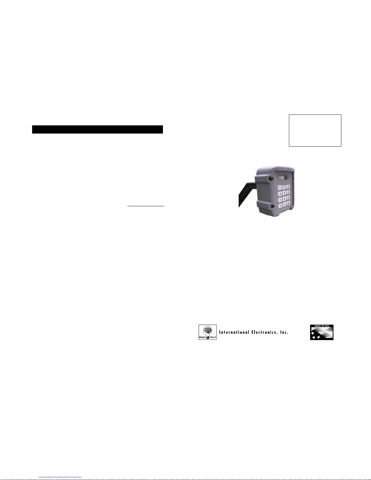
Oracle
(TM)
Wireless
Keypad
Thank you for purchasing the
Oracle Wireless Keypad. This
product has been designed and
manufactured in the USA,
utilizing the highest quality
standards available.
•
Controls up to four Gate Openers or other accessories
• Multiple Control Modes
•
Proximity Detector with Backlit key-pad after dark
•
Echo Confirmation Feedback
•
Up to 2 years on 4xAA batteries
• Multiple Power Saving Modes
•
Temporary one-time use/24 hour PIN numbers
• Use Several Keypads together in Multi-Keypad Mode
• Use Alternate Channel Groups to overcome
interference
• Oracle Wireless Keypad (OWK) has 2 models:
OWK5 – 5 Pin Codes
OWK250 – 250 Pin Codes
This device complies with part 15 of the FCC Rules. Operation is subject to the following two conditions:
(1) This device may not cause harmful interference, and (2) this device must accept any interference
received, including interference that may cause undesired operation.
International Electronics, Inc.
FCC ID: JLFOWK5
IC: 2666
A-OWK5
Country Of Origin: USA
Model OWK
9/6/2007
Patents Pending

FREQUENTLY ASKED QUESTIONS AND TROUBLESHOOTINGTABLE OF CONTENTS
- 1 -- 16 -
Preface
General Information………………………………………………………….…….……....3
Parts Supplied………………………………………………………..……………….……3
Section 1 – Installation
1.1
Installing the Oracle Wireless Keypad (OWK)…………………..……….....3
1.2
Initializing a new Master Pin Number………………………….………..……3
Section 2 – Gate Control Unit (GCU) Installation
2.1 Installing the batteries……………………………………………..…….….…4
2.2 Setting the GCU identity……………………………………….………….......4
2.3
Installing the GCU…………………………………………………………......5
Section 3 – Activating The Gate Control Unit (GCU)
Activating a GCU………………………………..……………..……………………..……5
Section 4 – General Operation
Opening a gate………………..…………………………………………………...………6
Section 5 – Pin Codes
5.1 User-level PIN numbers……………………………………………….….…..6
5.2 Removing User-level PIN numbers………………………………….….……6
5.3 Temporary User PIN numbers...………………………………..……….……7
5.4 Changing the Master PIN number………………………………..…….…….7
Section 6 – Oracle Wireless Keypad (OWK) Settings
6.1 OWK Keypad Brightness………..……………………………………….……7
6.2 Alternate Channel Group…………………………………………………..….8
Section 7 – Operating Modes
7.1 Multi-Keypad (OWK) Mode……………..…………………………..…………8
7.2 Multi-Keypad Default GCU Setting……………………………………..…….9
7.3 Party Mode……………………………………………………………..……….9
7.4 Vacation Mode………………………………………………………..………...9
7.5 Power-Save Mode……………………………………………………..……..10
Section 8 – Types of Batteries Used
Batteries……………………………………………………………………………..…….10
Section 9 – Quick List of Functions
Quick list of functions……………………………………………………………..………10
Section 10 – Appendix A
Detailed GCU Installation Instructions………………………………………………….11
Section 11 – Frequently Asked Questions and Troubleshooting
FAQ’s and Troubleshooting…………………………………………………...…………15
Why won’t the Wireless Keypad accept a PIN number?
The Wireless Keypad Unit will not learn a PIN # if it is the same number as
the factory’s reset code.
Why won’t my new gate controller work?
Make sure that it was taught to the Wireless Keypad Unit (see
Activating a
new Gate Controller
). If you hear a four-
beep error tone, the Wireless
Keypad Unit did not mate with the Gate Controller. If the Gate Controller is
#2, 3, or 4, make sure that the corresponding ID is set with dipswitches 1&2,
in the Gate Controller (See
Basic Gate Control Unit Installation
)
I need the Manufacturer’s Reset Code; to reset my Wireless Keypad
Unit
The
Wireless Keypad Unit’s
serial number is printed on the inside of the
Wireless Keypad Unit’s
mounting plate. Call our Product Suppor
t staff at
888.679.7994, for the reset code. You MUST have the
Wireless Keypad
Unit’s
serial number handy, to receive the reset code. Simply enter the reset
code on the
Wireless Keypad Unit’s
keypad and after one minute, the unit
will clear its memory and
you may re-teach the Keypad System.
Why do I hear a warbling two-
tone error sound when I activate a Gate
Controller?
The
Wireless Keypad Unit
is not communicating with the GCU. The GCU
may be out of range. If the units work properly when close together,
the
GCU may need to be mounted higher off the ground or on a different
surface. Metal, trees, or masonry cause the most interference.
If the units do not work when close together, the
Wireless Keypad Unit
has
not mated with that GCU. Double-check the GCU
’s ID (as set with
dipswitches 1 ??2, and re-teach it.
My Oracle System Network has very short range
Short transmission range is usually related to interference. If there is a
conflicting 900-MHz radio transmitter near-
by, you may need to have the
Oracle
Wireless Keypad Unit
use an alternate group of channels. See:
Alternate Channel Group Selection
.
Stucco:
When used in a dwelling with stucco or cement walls, the
RF range is reduced greatly. The Oracle Repeater will solve this
issue. Place the repeater close to the house to mitigate this problem.
Model OWK
9/6/2007
Patents Pending
1.1
1.2
ORACLE WIRELESS KEYPAD (OWK) INSTALLATION
PARTS SUPPLIED
- 15 -
INITIALIZING A NEW MASTER PIN NUMBER
INSTALLING THE OWK
- 2 -
GENERAL INFORMATION
The beeping you hear is the OWK prompting you to enter a new
Master Pin Number.
On the Keypad, press:
Followed by your four digit Master PIN Number (for example):
A tone indicates that the unit has accepted your Master PIN
Number.
Note: Is a ‘Cancel’ button to cancel any call or key sequence.
1 - Oracle Wireless Keypad (OWK)
1 – OWK Mounting Kit which includes:
4 – ¼ x 1 Steel Screws
4 – ¼ Washers
4 – ¼ Lock Nuts
4 – 8-32 X 1 5/8 Black Socket Assembly Screws
1 – Hex Key
The Oracle Wireless Keypad Unit has been designed specifically for
easy installation. After determining where you want the Wireless
Keypad Unit (OWK) to be mounted, just fasten the back panel to a
post or solid surface, using the included OWK mounting kit,
making
sure that is within easy reach of a visitor.
Place four ‘AA’ batteries in the OWK’s battery pack. You will hear a
periodic low-
volume beep, indicating that the unit is operational and
ready to be programmed with your secure master PIN number. Fo
r
longer battery life and better functionality, use lithium ‘AA’
batteries.
Install the front of the Wireless Keypad Unit onto the already
installed mounting plate, using the included Assembly screws and
hex key provided.
Utilizing Universal's newest wireless protocols, this keypad product line is
able to meet and exceed the most stringent security and environmental
requirements.
Ultra long Range,
Low Power Usage and its Two Way design, which
provides Confirmation Feedback
of Receiver Action make this system the
most robust available.
#
1
2
3
4
#
#
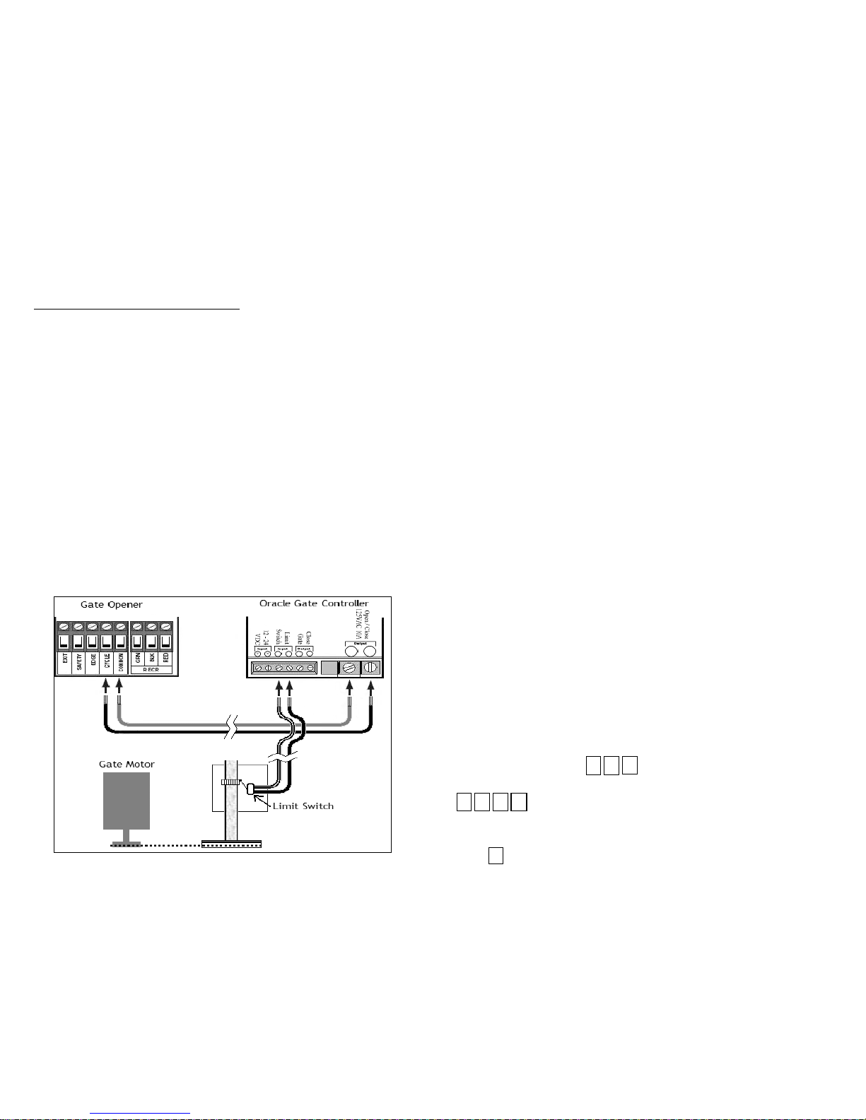
Sample Configuration 3:
Open, Close Gate and Verify Gate Status
Use this configuration when you wish to use the Reporter Gate System to open and
close your gate and check the gate’s actual status, connecting the Gate Controller
to a limit switch or external gate status indicator.
Enable or disable the Auto-close feature on your Automatic Gate Opener.
Connect Reporter Gate Controller Contacts 7 and 8 to “Strike Open”, “Open Only”,
“Remote” or a similarly named contact pair on your Automatic Gate Opener.
Please refer to your product-specific manual for wiring information.
Connect Contact 2 to Ground, COM, or (-) on your Automatic Gate Opener.
Flip Gate Controller Dipswitch #3 to the UP position to enable status checking.
If your Automatic Gate Opener
has a “Close” or “Close Only” contact pair (e.g.
connecting like a 3-
button station), connect Contacts 5 and 6 to the “Close”
contacts and flip Gate Controller Dipswitch #5 to the UP position.
If desired, enable Auto-close on the Gate Controller by flippi
ng Gate Controller
Dipswitch #6 to the UP position. If you use this feature, disable auto-
close on your
Automatic Gate Opener.
Connect terminals #3 and #4 across the “Gate Closed” limit switch. Polarity does
not matter.
Model OWK
9/6/2007
Patents Pending

GCU ID
SW1
SW2
1
off
off
2onoff
3
off
on
4onon
2.1 INSTALLING THE BATTERIES
2.2 SETTING THE GATE CONTROLLER IDENTITY
GATE CONTROL UNIT (GCU) INSTALLATION
- 14 - - 3 -
Note: Is a ‘
Cancel’ button to cancel any call or key sequence.
Note:
To set the identity of
GCU #2, you would position
the dipswitches as seen
below.
You can use up to 4 GCU’s with each OWK utilized. If you use more than
1 GCU, the additional units must have their identity set. Changing
dipswitches #1 & #2 on the Gate Control Unit sets the Gate Controller
Identity. (See below.)
Open the GCU by holding the box/shell portion of the unit. Then, while
tilting the bottom section (where the wire is located), pull the box/shell off.
Insert 4 ‘AA’ batteries into the exposed battery holder.
Note: If used in locations that will be below -10°C (20°F), Lithium batteries
are recommended.
Note: Leave the box/shell off until after activation is complete.
Dipswitch Block
Learn Button
Terminal
Sample Configuration 1:
Open Gate Only
Use this configuration when you wish to use the Reporter Gate System as
an open-
only system, which automatically closes, based on a timer or a
magnetic loop.
Enable the Auto-close feature on your Automatic Gate Ope
ner. Connect the
Reporter Gate
Controller as shown in the Basic Gate Controller
Installation
diagram. Please refer to your product-
specific manual for wiring
information. On the Reporter Intercom, disable gate status checking (as
described above).
Sample Configuration 2:
Wiring to separate OPEN and CLOSE terminals
Use this configuration when you wish to use the Reporter Gate System to
open and close your gate and check the gate’s last known status, without
connecting to a limit switch or external gate status indicator.
Disable the Auto-close feature on your Automatic Gate Opener.
Connect Contact 2 to Ground, COM, or (-) on your Automatic Gate Opener.
Connect Reporter Gate Controller Contacts 7 and 8 to “Strike Open”, “Open
Only”, “Remote” or a
similarly named contact pair on your Automatic Gate
Opener. Please refer to your product-specific manual for wiring information.
If your Automatic Gate Opener has a “Close” or “Close Only” contact pair
(e.g. connecting like a 3-button station), connect C
ontacts 5 and 6 to the
“Close” contacts.
Slide Gate Controller Dipswitch #5 to the UP position.
If desired, enable Auto-
close on the Gate Controller by flipping Gate
Controller Dipswitch #6 to the UP position.
LED
Model OWK
9/6/2007
Patents Pending

2.3 INSTALLING THE GATE CONTROL UNIT (GCU)
Using Additional Contact / Clearance Sensors
- 4 - - 13 -
3.0 ACTIVATING A GATE CONTROL UNIT (GCU)
Open/Closed Contact Sensors
Dipswitch #3 Dipswitch#7 Dipswitch#8
No contact sensors used
OFF OFF OFF
“Closed” li mit switch wired to
terminals #3 and #4
ON OFF OFF
“Open” limit switch wired to
terminals #3 and #4
ON ON OFF
Additional “Close
d” limit
switch or senso r wired to
terminals #3 and #4
ON OFF ON
Additional “Ope ned” limit
switch or senso r wired to
terminals #3 and #4
ON ON ON
Mount the Oracle Gate Controller near your Automatic Gate
Opener’s control panel or motor. Most gate motors have simple
relay connections (often labeled COMMON and CYCLE
) that
connect to the two large OPEN/CLOSE
relay outputs on the Oracle
Gate Controller.
Note:
For more detailed installation information, refer to Appendix A
on pg. 15.
When you are ready to activate the GCU, press the LEARN button
on the GCU (see page 4 for location of the LEARN button), for one
second. The LED will light up solid for up to 20 seconds.
Within 20 seconds, on the GAP,
Enter your
Master PIN Number
(for example):
Followed by the Gate Controller’s Identity:
The GAP will give a double-
beep and the GCU LED will blink 3
short blinks to indicate a successful activation.
Note: If the GAP sounds a 4-
beep error tone or the GCU gives 3
double blinks, then chec
k the FAQ section for the possible
solution.
If you only have one GCU then you are finished and can proceed to
the next step. For additional GCU’s, repeat the process until all
GCU’s have been successfully activated.
Note: You can now assemble the GCU b
y snapping the
box/shell back onto the unit.
(1 - 4)
Selecting Gate Controller “ON” Time
For most connections to an Automatic Gate Opener, the default setting of ½
second is best. However, for connection to yard lights, cameras, etc., you may
wish to adjust how long the connected device stays on.
Gate Controller
“ON” Time
Dipswitch
#3
Dipswitch
#4
½ second –
No Limit Switch
OFF OFF
½ second –
Using a Limit Switch
ON OFF
10 seconds OFF ON
30 seconds ON ON
NOTE:
For most gate system wiring, dipswitch #4 should be left “OFF.” If you wire your gate
controller to a limit switch, dipswitch #3 should be turned “ON”.
Enabling the Auto
-
Close Feature
By enabling the Auto-
Close feature, the Gate Controller will attempt to close the
gate 45 seconds after it is opened. This feature will work better if your
configuration has at least one of the following elements:
Separate Open / Close Terminals,
A “Gate Closed” Sensor or limit switch, or
A “Gate Open” Sensor or limit switch
Otherwise, the Gate Controller must assume that the gate has not opened or
closed for any other device.
Auto-Close Feature Dipswitch #6
OFF (disabled) OFF
ON (enabled) ON
Warning:
Please remember safety! Do not enable auto-
close where it might
pose a risk of entrapment, causing injury, death, or damage to vehicles.
NOTE:
To power an additional c ontact sensor t hat is NOT already connected to your gate system, short
terminal #3 to ground, connects the switch across terminals 3 and 4, and turn dipswitch #8 ON.
1
2
3
4
Model OWK
9/6/2007
Patents Pending

4.0 OPENING A GATE
PIN NUMBERS
5.2 REMOVING USER-LEVEL PIN NUMBERS
- 12 - - 5 APPENDIX A - DETAILED GCU INSTRUCTIONS
5.1 USER-LEVEL PIN NUMBERS
To remove an additional PIN, on the OWK:
Enter your
Master PIN Number
(for example):
Followed by:
Press:
Enter the PIN number you want to remove (for example):
The OW K will give a double beep indicating the PIN has been removed or
a triple beep indicat
ing a PIN has been entered that does not exist. The
Master PIN cannot be deleted.
The W ireless Keypad can support up to 5 PIN numbers with the OWK5 or
up to 250 PIN numbers with the OWK250, for other users.
To add an additional PIN number, on the OWK:
Enter your Master PIN Number (for example):
Followed by:
Enter a new PIN number (for example):
To limit the new PIN number to a single GCU, enter the PIN number
followed by the GCU identity (1-4), resulting in a five digit PIN number.
The OWK will give a single beep as the new PIN number is accepted.
1
9
"BEEP"
From left to right, Gate Controller
Terminals are:
−
Optional power input. +9Vto +24VDC.
Make sure that your gate’s DC power
supply “Ground” is wired to terminal 2.
−
Ground or Common terminal.
−
Limit switch input A. Wire such that
when the limit switch is closed, terminal
4 is shorted to terminal 3.
− Limit switch input B. Wire such that
when the limit switch is closed, terminal
4 is shorted to terminal 3.
−
Secondary Relay Contact A. Up to 120VAC LOW CURRENT contact. Max ½
amp. Typically wired to optional “Close Gate” input on Automatic Gate
Opener.
−
Secondary Relay Contact B. Up to 120VAC LOW CURRENT contact. Max ½
amp. Typically wired to optional “Close Gate” input on Automatic Gate
Opener.
−
Primary Relay Contact A. Up to 120VAC. Max 10 amps. Typically wired to
“Open Gate”, “Open/Close” or “Remote” input on Automatic Gate Opener.
−
Primary Relay Contact B. Up to 120VAC. Max 10 amps. Typically wired to
“Open Gate”, “Open/Close” or “Remote” input on Automatic Gate Opener.
7
"BEEP"
To open a gate from the OWK, enter any valid PIN number. With multiple
GCU’s, enter the PIN number followed by the GCU identity (1-4).
2
3
4
1
2
3
4
1
4
3
2
1
2
3
4
#
#
#
Model OWK
9/6/2007
Patents Pending

5.4 CHANGING THE MASTER PIN NUMBER
ORACLE WIRELESS KEYPAD (OWK) SETTINGS
6.1 OWK KEYPAD BRIGHTNESS
8.0 BATTERIES
7.5 POWER-SAVE MODE
- 6 -
QUICK LIST OF FUNCTIONS
- 11 -
5.3 TEMPORARY USER PIN NUMBER
A temporary PIN number can be issued with an OWK5 (6 for an
OWK250), for a 1 time only use, within a 24 hour time period.
To issue a temporary PIN number, on the OWK:
Enter your Master PIN Number (for example):
Followed by:
Enter the temporary PIN number (for example):
To limit the new PIN number to a single Gate Controller, enter the
PIN number followed by the Gate Controller ID (1-
4) that it will
access, resulting in a five digit PIN number.
The Wireless Keypad Unit will give a single beep as the new PIN
Number is accepted.
Power-
Save Mode will increase battery life by reducing power consumption
and limiting some features. (See NOTE below.) In Power-Save mode
,
the keypad will only light up when a key is pressed.
To enter Power-Save Mode:
Enter the Master PIN Number (for example):
Followed by:
To exit Power-Save Mode:
Enter the Master PIN Number (for example):
Followed by:
The Gate Controller uses four ‘AA’ batteries. The average life of the Gate
Controller’s batteries is a year-and-a-half, depending on use.
The Wireless Keypad Unit uses four ‘AA’ Alkaline batteries. The average
life of the Wireless Keypad Unit’s batterie
s is a year with all functions
enabled. Enabling
Power-save Mod
e can extend the battery life up to two
years.
Enable OWK Learn Mode
PIN 05
Add User-Level PIN numbers PIN 9 PIN
Add User-Level PIN numbers w/GCU restrict PIN 9 PIN (1-4)
Add a Temporary PIN number PIN 51 PIN
Add a Temporary PIN number w/GCU restrict PIN 51 PIN (1-4)
Removing PIN numbers PIN 7 ### PIN
Change the Master PIN number PIN 09 ### PIN
OWK Brightness Control PIN 08 (1-3)
Place GAP in Multi-GAP Passive Mode PIN 56
Default GCU #3 to the Passive OWK PIN 58
Default GCU #4 to the Passive OWK PIN 59
Place OWK back to Active Mode PIN 57
Party Mode PIN 54
Vacation Mode PIN 52
Exit Vacation Mode PIN 53
Power-Save Mode PIN 03
Exit Power-Save Mode PIN 04
Alternate Channel Set PIN 55 (1-3)
1
2
3
4
1
2
3
4
0
3
0
4
"BEEP"
5
1
1
2
3
4
4
3
2
1
To change the Master PIN Number, on the OWK:
Enter the existing Master PIN Number (for example):
Followed by:
Press:
Enter the NEW Master PIN Number (for example):
The Wireless Keypad Unit will give a single beep as the new PIN
Number is accepted.
#
#
#
0
9
"BEEP"
1
2
3
4
4
3
2
1
When it is dark out, the Wireless Keypad Unit uses an Infrared
proximity sensor to light up the keypad when you come within five
feet of it or when a button is pressed. This feature is disabled in
Power Save Mode (see
Power-save Mode
).
To brighten or dim, on the OWK:
Enter the Master PIN Number (for example):
Followed by:
Enter:
The Wireless Keypad Unit will give a single beep as the new level is
accepted. The default level is 2.
1, 2, or 3
8
0
1
2
3
4
Model OWK
9/6/2007
Patents Pending

7.2 MULTI-OWK DEFAULT GCU SETTING
OPERATING MODES
7.3 PARTY MODE
6.2 ALTERNATE CHANNEL GROUP SELECTION
Note: Both steps 1 & 2 must occur within 2 minutes of each other.
- 10 -
7.1 MULTI-KEYPAD (OWK) MODE
7.4 VACATION MODE
- 7 -
1. On the OWK to be set to Passive:
Enter the
Master PIN Number
(for example):
Followed by:
2. On the OWK to be set to Active:
Enter the
Master PIN Number
(for example):
Followed by:
The OWK can be set to one of three alternate operating channel groups, to
overcome range-reducing interference from conflicting radio transmitters.
To alternate operating channel groups, on the OWK:
Enter the
Master PIN Number
(for example):
Followed by:
Enter:
The Wireless Keypad Unit will give a single beep as the new channel group
is accepted. The default setting is channel group 1.
To keep your gate open during a party or other activity, so the gate
won’t have to open with the arrival of each guest, you can set the
Wireless Keypad Unit to keep the gate open, until it is cycled closed.
To use this setting, the Gate Control Unit MUST b
e connected to an
external +12 Volt power supply.
To enter Party Mode, on the Active OWK:
Enter the
Master PIN Number
(for example):
Followed by:
To close the gate and exit Party Mode, cycle the gate by entering a
PIN number or by pressing the button on a Remote or Intercom.
If you are going to be gone for an extended length of time, the unit
can be put into a Deep Sleep mode to conserve power and will only
respond to the Master PIN number being entered on the Wireless
Keypad Unit.
To enter Vacation Mode:
Enter the Master PIN Number (for example):
Followed by:
To exit Vacation Mode:
Enter the
Master PIN Number
(for example):
Followed by:
Note:
If the Passive OWK doesn’t learn the network code, it will give an
error tone and return to Active mode. At any time to exit Passive Mode and
return a OWK to Active mode, enter the Master PIN number, followed by
“57”.
A Passive OW K defaults to activating GCU #2 (See
Basic Gate
Control Unit Installation
) when it is activated by a PIN code
entered on that keypad.
To have the Passive OWK activate GCU #3, on the Passive unit:
Enter the Master PIN Number (for example):
Followed by:
To have the Passive OWK activate GCU #4, on the Passive unit:
Enter the Master PIN Number (for example):
Followed by:
1
1
1
2
2
3
3
4
4
5
2
5
3
2
3
4
5
4
1
2
3
4
1
2
3
4
5
8
5
9
3
1
4
0
5
2
3
2
4
5
6
"BEEP"
1
2
3
4
5
5
1, 2, or 3
A W ireless Keypad Unit (OW K) can be set to Passive Mode, to work with
multiple Wireless Keypad Units (at a second entrance for example). The
Passive OWK will become an accessory to the Active OWK.
1
Model OWK
9/6/2007
Patents Pending

- 8 - - 9 -
Model OWK
9/6/2007
Patents Pending

- 12 - - 9 -
Model OWK
9/6/2007
Patents Pending

- 10 - - 11 -
Model OWK
9/6/2007
Patents Pending

Model OWK
9/6/2007
Patents Pending

Model OWK
9/6/2007
Patents Pending

Model OWK
9/6/2007
Patents Pending

Model OWK
9/6/2007
Patents Pending

Model OWK
9/6/2007
Patents Pending

Model OWK
9/6/2007
Patents Pending

Model OWK
9/6/2007
Patents Pending

Model OWK
9/6/2007
Patents Pending

Model OWK
9/6/2007
Patents Pending

Model OWK
9/6/2007
Patents Pending

Model OWK
9/6/2007
Patents Pending
 Loading...