


SRA/SFX2100 Series Satellite
Receiver Appliance
User’s Guide

Preface
NOTE: The screen
captures shown in
this User’s Guide are
for reference only
and may not exactly
match the pages that
are displayed on your
browser. Not all
receiver models
and/or versions of the
application firmware
will support all
features described in
this guide. If you
have any questions
regarding availability
of certain features,
please contact
International
Datacasting’s
Customer Service
Department (see
Chapter 5I).
All rights are reserved by International Datacasting Corporation. This User’s Guide contains
the valuable properties and trade secrets of International Datacasting Corporation,
embodying substantial creative efforts and confidential information, ideas or expressions. No
part of this User’s Guide may be reproduced, translated or transmitted in any form or by any
means without the prior written permission of this company.
The information in this document is subject to change in order to improve reliability, design or
function without prior notice; all changes are incorporated into new editions and/or revisions.
In no event will we be liable for technical or editorial errors or omissions contained herein; nor
for incidental, special or consequential damages from the furnishing, performance or use of
this manual.
SRA/SFX2100 Series Satellite Receiver Appliance
International Datacasting Corporation Part No. 90076610-50
Record of Revisions
International Datacasting Corporation is constantly improving its products and therefore the
information in this document is subject to change without prior notice. International
Datacasting makes no warranty of any kind with regard to this material, including but not
limited to the implied warranties of merchantability and fitness for a particular purpose.
No responsibility for any errors or omissions that may pertain to the material herein is
assumed. International Datacasting makes no commitment to update or to keep current the
information contained in this document. International Datacasting assumes no responsibility
for use of any circuitry other than the circuitry employed in International Datacasting’s
systems and equipment.
Copyright © 2003-2004, Rev. 2, International Datacasting Corporation
All rights reserved. Printed in Canada.
LINUX is a registered trademark of Linus Torvalds, in the united States and other countries.
Microsoft, Windows and Windows NT are registered trademarks of Microsoft Corporation in the United States and/or
other countries.

Table of Contents
Chapter 1 - Introduction 1
General 1
SRA2100 IP/DVB Satellite Router Appliance- Product Overview 2
Standard Features 2
Options 3
Router Functionality 3
Mechanical Packaging 4
SFX2100 IP/DVB Satellite Multimedia Appliance - Product Overview 4
Multimedia Applications 4
Multimedia Player Application 4
Chapter 2 - Installation 7
What You Should Have Received 7
Front Panel 8
Rear Panel 10
Equipment Installation 13
Power up procedure 14
Chapter 3 - Getting Started 15
Status and Control of the Satellite Receiver 15
Controlling the Receiver with the Terminal Interface 15
Help 16
exit 16
SetCarrier 16
GetCarrier 17
SetLNB 18
GetLNB 18
GetLNBOffset 19
ResetLNBOffset 19
GetRFMetrics 19
ClearRS 20
SetIP 20
GetIP 20
AddRoute 21
DeleteRoute 21
GetRoutingTable 22
SetSNMPConfig 22
ResetSNMPConfig 22

ResetFirewall 23
GetInfo 23
GetDebug 23
ClearDebug 24
GetHealth 24
ConfigEth 24
RestoreFactorySettings 25
SetPassword 25
Ping 25
Controlling the Receiver with the Web GUI 26
Controlling the Receiver with SNMP 30
Controlling the Receiver with NetManager 30
Chapter 4 - Web GUI Operation 31
Main Menu Page 31
Logout Icon 31
IDC Logo 31
Receiver Identity 31
Main Menu Tool Bar Area 32
Main Display Area 33
DVB Carrier A/B Lock Status 33
RF Metrics Display Area 34
RF Metrics Refresh Rate Selection 35
Main Menu Tool Bar 35
The Action of the Mouse 37
Common Menu Items 37
Drop-down Selection Boxes 38
Identity 39
DVB Carrier 42
DVB Carrier Definitions 42
LNB Attributes 45
(The LNB Offset) 45
Data Delivery 48
PIDs and Ports 50
(PID Filtering and PID Types) 50
IGMP 58
Static Routing 61
Multicast Routing 65
Source NAT 71
Destination NAT 76
Filtering 81
Firewall 86
TTL Translation 91
XD Suite (SFX only) 95
Player (SFX only) 104
Logging 105
Metrics 109
Satellite Interface Metrics 111
Utilities 119
Apache Webserver (SFX2100 only) 119
Ethernet Configuration 119
SFX Home Page (SFX2100 only) 120
Local Applications (SFX2100 only) 120

TCP Dump Utility 121
Traceroute Utility 122
Date and Time 123
Password Manager 124
Ping Utility 125
Restart Receiver 127
GUI Server Setup 128
Samba Windows File Sharing (SFX2100 only) 130
Backup and Restore (SFX2100 only) 130
DHCPd Configuration (SFX2100 only) 130
Upgrade 131
Documents (SFX only) 133
Chapter 5 - Troubleshooting, Warranty and Contact Information 135
Troubleshooting 135
Preventative Maintenance 135
Troubleshooting Procedures 136
Contacting Your Supplier 136
Shipping & Packaging 136
Warranty & Service 137
Warranty Period 137
Warranty Coverage Limitations 137
Warranty Replacement & Adjustment 138
Liability Limitations 138
Warranty Repair Return Procedure 138
Non-Warranty Repair 139
Contacting IDC for More Information 139
Appendix A - SRA2100 Series Specifications 141
Available Models in this Series 141
Specifications 142
RF Subsystem 142
Front Panel Indicators 143
Synchronous Port 143
Asynchronous Port 143
Net Ports (#1 and 2) 144
Terminal Port (for Terminal Interface) 144
Status & Control 144
Physical (1U Rackmount Unit) 144
Environmental Considerations 144
Certification 144
Options 145
ASI Port 145
DVB Conditional Access System (CAS) 145
Irdeto Cyphercast 145
Other Options 145
Physical (Cube Unit) 145
Appendix B - SFX2100 Series Specifications 147
Available Models in this Series 147
Specifications 148
RF Subsystem 148
Front Panel Indicators 149

Synchronous Port 149
Asynchronous Port 149
Net Ports (#1 and 2) 150
Terminal Port (for Terminal Interface) 150
Status & Control 150
Storage 150
Physical (1U Rackmount Unit) 150
Environmental Considerations 150
Certification 151
Options 151
ASI Port 151
DVB Conditional Access System (CAS) 151
Irdeto Cyphercast 151
Other Options 151
Physical (Cube Unit) 151
Appendix C - Important EMI & Safety Certification Information 153
Receiver Installation 153
Exterior Equipment Installation 154
Operating & Cleaning 154
Service 155
EMI/EMC Certification 155
Appendix D - ASI Output Option 157
Web GUI Operation 157
Appendix E - Irdeto Cyphercast Option 161
Pre-installation Procedure 161
Inserting The Irdeto Smart Card 161
Web GUI Operation 163
Front Panel LED Indications 165
Appendix F - DVB Conditional Access System (CAS) Option 167
Pre-installation Procedure 167
Inserting The CA Module 167
Web GUI Operation 169
Front Panel LED Indications 171
Appendix G - Performance Graphs 173
Appendix H - Glossary 175

SRA/SFX2100 SERIES SATELLITE RECEIVER
Chapter 1
Introduction
International Datacasting Corporation (IDC) would like to thank you for purchasing
the SRA2100 or SFX2100 Series SuperFlex Satellite Receiver Appliance. At
International Datacasting, we take pride in our products and believe the satellite
receiver that you have chosen will satisfy your needs for years to come. Satellite
Communications is our business and quality is our goal. We welcome your
comments and respect your opinions.
The SRA and SFX family is an important leap forward in performance and
functionality. These products combine IDC’s experience of 20 years as a long-time
leader in the design and manufacture of satellite receivers for edge applications with
a proven ability to provide complete systems solutions. This product is designed to
provide for the flexibility, functionality and high reliability required in today’s leadingedge applications.
General
Throughout this manual, the SRA2100 or SFX2100 series SuperFlex satellite receiver
appliance will be referred to as simply the “receiver”. Unless explicitly stated, receiver
references can be exchanged with any model in the SRA2100 or core SFX2100 family
(e.g. SRA2100B, SFX2100R, etc). Please refer to the Appendices corresponding to your
specific model to determine which features are available with your unit. The content of
this manual will depict a fully featured SRA2100x or core SFX2100x (no multimedia
applications) receiver.
This chapter provides a brief overview of the SRA2100 family and SFX2100 family of
receiver appliances.
1

SRA/SFX2100 SERIES SATELLITE RECEIVER
SRA2100 IP/DVB Satellite Router Appliance-
Product Overview
The SuperFlex SRA2100 family of satellite router appliances is the latest generation of
advanced DVB/IP satellite router appliances available from IDC. The SRA2100 family is an
industrial-grade satellite receiver with advanced router functionality capable of filtering up to
250 PIDs and outputting over 70mb/s. The SRA2100 family features dual high-speed
Ethernet outputs and a new web browser based interface for local and remote status and
control.
The SRA2100 family is a next generation product line that evolved directly from IDC’s
proven SR2000 and SR2001 family of DVB-S receivers. The significant new features and
options are summarized below.
Standard Features
• DVB transport format compatible ISO/IEC 13818 with filtering up to 250 PIDs.
• QPSK DVB compliant demodulator, or QPSK/8PSK/16QAM compliant
demodulator, depending on model.
• Embedded Linux operating system for maximum performance and stability.
• Dual Ethernet ports: two full capability 10/100 Base-T Ethernet ports to support
complete routing and subnetting. Now operators can elect to use one output for
multicasting and a second for unicasting.
• Asynchronous and Synchronous outputs – standard interfaces for serial protocol
applications and ease of integration into legacy satellite networks.
• Intel processor based – most powerful receiver on the market; processors scalable
for even more power, leaving available processing power for future applications.
• Available in one rack unit-high model (with or without rack-mount brackets/ears).
• On board watchdog timer for failsafe operation.
• Asynchronous Terminal interface on separate connector for easy local installation
and metrics using minimal support equipment.
• SNMP Manageable using MIB-II (relevant portions) and IDC Enterprise MIB.
• Web browser compatible Graphical User Interface (GUI)
• Compatible with IDC’s proven NetManager2 for over-the-satellite network
management.
• Return channel via IP/Ethernet or optional PPP/telephone modem return channel
interface.
2

SRA/SFX2100 SERIES SATELLITE RECEIVER
• Unicast and multicast IP Routing.
• IP Filtering and Firewalling.
• Source & Destination Network Address Translation.
• Secure background firmware/software downloading – the SRA2100 always has
most current code.
• Front panel indicators for Lock, Status, Control, and data traffic.
• Fully interoperable with IDC’s family of SuperFlex DVB products.
Options
• (SRA2100R or SRA2100MR series Only) Integrated IP security client and
smartcard reader (requires a software key to enable) – works with CypherCast, the
latest IP Security conditional access system available from Irdeto Access.
• (SRA2100B or SRA2100MB series Only) Integrated DVB Conditional Access
System (CAS) Common Interface (CI) slot for a CA Module (CAM) and Smartcard.
This interface supports a number of CA systems, including Irdeto Access M-Crypt
and NagraVision.
• Automatic redundancy peering.
• Industry standard PCI option slot – telephone modem available today, other PCI
options will be available for future applications for custom applications upon
request.
• S-Video, Composite Video, Parallel Output, USB connectors, Keyboard, mouse,
AC97 audio, IrDA and monitor connections available and reserved for future
applications and for custom applications upon request.
Router Functionality
The SRA2100 series have an integral microprocessor running the highly reliable Linux realtime operating system. This combined with the two Ethernet ports provides highly flexible
router functionality. The following networking and routing protocols are supported:
• ICMP, IGMP, SNMP, DHCP, NAT
• DVB MPE
• PPP (with modem option)
• MAC Filtering
• Multicast Routing
3

SRA/SFX2100 SERIES SATELLITE RECEIVER
Mechanical Packaging
The SRA2100 series is available as a low-profile 1RU high model for rack mount and
desktop installations. The SRA2100 series comes with easy to read front panel indicators
and a full suite of industry standard rear panel interfaces, for ease of implementing standard
and custom-defined network configurations.
SFX2100 IP/DVB Satellite Multimedia Appliance -
Product Overview
The SFX2100 family is functionally equivalent to the SRA2100 family. The addition of a
minimum 40 Gbyte integrated hard drive and Datacast XD software makes it ideal for those
multimedia applications where a reliable satellite receiver and computer are required in an
integrated self-contained package. Many of the optional interfaces on the SRA are
standard on the SFX.
Multimedia Applications
The SFX2100 series of satellite multimedia server appliances comes complete with
Datacast XD, IDC’s leading multimedia content distribution software ([see separate product
information). With Datacast XD, the SFX2100 is a powerful server with advanced routing
capabilities that can be used as-is for a wide range of file transfer, streaming media and
multimedia content distribution applications.
The SFX2100 can also be configured for specific customer applications and IDC’s technical
resources are available to assist with this – including specialized and proprietary
configurations for Original equipment Manufacturers (OEM’s).
In addition, IDC intends to develop a family of application-specific software packages to help
enable specific business models. An example of an application that is currently available is
described in the following paragraphs.
Multimedia Player Application
The Multimedia Player Application is intended to create and present multimedia displays for
kiosks. Functional elements of this application are summarized as follows:
• Ability to play video files, optionally from a carousel playlist.
• Ability to play audio files, optionally from a carousel playlist.
• Ability to display graphics files.
• Built-in Apache web server.
• Streaming MPEG2 and MPEG4 video/audio with MPEG Accelerator PCI card
option.
4

SRA/SFX2100 SERIES SATELLITE RECEIVER
• Built-in Samba Daemon, which allows networked PCs running other operating
systems such as Windows®, to access the files deposited by XD on the integrated
hard drive.
5

SRA/SFX2100 SERIES SATELLITE RECEIVER
This page is intentionally left blank.
6

SRA/SFX2100 SERIES SATELLITE RECEIVER
Chapter 2
Installation
This chapter provides information to familiarize you with the SRA2100 and basic SFX2100
series satellite receiver appliance, as it comes out of the box. This information can be used
to step through a preliminary investigation of the unit you have received, as well as initially
applying power to ensure that it is operating correctly and has not been damaged during
transit.
The illustrations that are provided in this chapter identify indicators and connectors on the
satellite receiver, both in the rack mount and cube configurations. Acquaint yourself with
these parts as illustrated, and refer to the physical unit itself. Throughout the remainder of
this guide, reference will be made to these parts. There are no adjustable components on
the receiver, only display indicators.
Varying levels of Status and Control for configuration of the satellite receiver are available
through one of the following: locally using the Terminal Interface, locally or remotely using
the Web based Graphical User Interface (GUI), remotely using SNMP, or remotely using
NetManager. Status and control via these methods is detailed in Chapters 3 and 4 of this
manual.
What You Should Have Received
You should have received the following package:
• One (1) SRA2100 or SFX2100 series satellite receiver appliance;
• One (1) power cord, suitable for use in your country;
• One (1) copy of this manual (optional) – also available online from the IDC
customer service FTP site – see Chapter 5 for contact information.
It is highly recommended that you retain the box and foam packaging that came with the
unit, in the rare event that it has to be shipped back for repair.
7

SRA/SFX2100 SERIES SATELLITE RECEIVER
N
k
Front Panel
Once you have removed the satellite receiver from the box, please familiarize yourself with
the front panel. Refer to Figures 2-1 for the location of the indicators. These are described
in the table under the figure.
Lock
Status
Control
R/W
Figure 2-1 Front Panel Indicators – Rack Mount Unit
Indicator Description
LOCK Purpose: provides indication of receiver lock to the incoming
satellite DVB carrier on the L-Band input.
Colour: off/red/green, where:
Off – no power is applied to the receiver.
Solid Green – indicates that the demodulator is locked onto the
satellite DVB carrier.
Solid Red – the demodulator is not locked onto the DVB carrier.
Sync
Async
etwor
Options
STATUS Purpose: provides indication of various power-up states of the
receiver, including LNB DC power status to the L-Band
connector.
Colour: off/red/green/orange, where:
Off – no power is applied to the receiver.
Solid Green – normal operation and one of:
1. the LNB is being powered by the receiver; current draw is
between 50 and 350 mA; or
2. the receiver has not been configured to power the LNB.
Solid Orange – power is being supplied to the LNB, and it is
under current (power drawn is <50 mA, which may possibly
indicate an open circuit).
Solid Red – boot and normal operation, can be one of:
1. during the boot, start-up and initialization of the receiver
application firmware, remains red until startup is
8

SRA/SFX2100 SERIES SATELLITE RECEIVER
Indicator Description
completed, then turns solid green, orange, or remains
red, depending on LNB status; and
2. during operation, power is being supplied to the LNB and
it is over current (power drawn is >350 mA, which may
possibly indicate a short circuit).
CONTROL Purpose: provides indication of the authorization for the receiver
to process control commands from the Network Control Channel
(NetManager NCC PID stream for the DVB Carrier – see Chapter
4).
Colour: off/green, where:
Off – normal operation, receiver is not authorized to process
commands from the Network Control Channel on the NCC PID
for the DVB Carrier.
Green - normal operation, receiver is authorized to process
commands from the Network Control Channel.
Flashing Off/Green – indicates that DVB packets are
being received on the NCC PID.
R/W Purpose: provides indication of read/write activity of the storage
device in the receiver (either compact flash disk or hard drive,
depending on model).
Colour: off/green, where:
Off – no storage device activity.
Flashing Off/Green – storage device read/write activity, as well as
an indication that the receiver is booting after power-up.
NETWORK Purpose: provides indication of the authorization and data activity
on the satellite network interface.
Colour: off/green/orange, where:
Solid Green – satellite network interface is authorized (enabled),
but there is no data activity.
Flashing Off/Green – satellite network interface is authorized and
there is data activity on one or more of the selected MPE PIDs
(see Chapter 4). If the DVB CAS or Cyphercast option is
installed, this also indicates that the data is being decrypted.
Flashing Off/Orange – DVB CAS or Cyphercast option is
installed, satellite network interface is authorized and there is
data activity on one or more of the selected MPE PIDs (see
Chapter 4). However, the data is not being decrypted.
SYNC Purpose: provides indication of the authorization and data activity
Off – satellite network interface is not authorized.
9

SRA/SFX2100 SERIES SATELLITE RECEIVER
Indicator Description
on the synchronous interface.
Colour: off/green, where:
Solid Green – the SYNC port is authorized, but there is no data
activity.
Flashing Off/Green – the SYNC port is authorized and there is
data activity.
Off – the SYNC port is not authorized.
ASYNC Purpose: provides indication of the authorization and data activity
on the asynchronous interface.
Colour: off/green, where:
Solid Green – the ASYNC port is authorized, but there is no data
activity.
Flashing Off/Green – the ASYNC port is authorized and there is
data activity.
Off – the ASYNC port is not authorized.
OPTIONS Purpose: provides operational status indication of options
installed in the receiver, as applicable. Currently, status is
provided for the conditional access (Cyphercast in the
SRA/SFX2100R series and DVB CAS in the SRA/SFX2100B
series) options.
Colour: off/green, where:
Solid Green – conditional access option is installed.
Flashing Off/Green – for Cyphercast option EMM/ECM packets
are being received, or for DVB CAS option PAT/PMT tables are
being received.
Off – the Cyphercast or DVB CAS option is not installed.
Rear Panel
Once you have acquainted yourself with the front panel and the associated indicators, turn
the receiver around so that the rear panel is fully visible. Please refer to Figures 2-2. A
description of each of the visible connectors on the rear panel is provided in the table after
the figure.
10

SRA/SFX2100 SERIES SATELLITE RECEIVER
Universal
AC Power
Keyboard (K) &
Mouse (M) Port
(SFX)
Parallel Port
(future expansion)
Dual 10/100BaseT
Ethernet Ports
PCI Option
slot
Async Port
(RS-232)
Terminal
Interface Port
SVGA Video
Port (SFX)
Multiple USB
ports
(future
expansion)
TV Video
Output
(SFX)
Left (L) & Right (R)
Conditional
Access: CAM or
SmartCard
(behind plate)
Audio Outputs
(SFX)
L-Band
Input
from LNB
Sync Port
(RS-422)
Figure 2-2 Rear Panel Connectors – Rack Mount Unit
Connector Description
AC Power The Alternating Current (AC) inlet is the main power disconnect.
The power cord connector is used to provide AC power to the
satellite receiver. The power requirements for this equipment is
quite flexible, with an acceptable power range of 100 to 240
VAC at 50 or 60 Hz.
ASYNC Port This is a 9-pin RS-232 (DTE) DE-9P (male) connector. It is
used as a unidirectional (output) low speed asynchronous data
port. The pinouts for this port are as follows:
PIN Acronym Reference
1 DCD Data Carrier Detect
2 RD Receive Data
3 TD Transmit Data
4 DTR Data Terminal Ready
5 GND Ground
6 DSR Data Set Ready
7 RTS Request To Send
8 CTS Clear To Send
9 RI Ring Indicator
K (Keyboard) & M
(Mouse) Ports
These are standard PS/2 type keyboard and mouse connectors,
used when keyboard, monitor, and mouse are required for some
SFX applications.
TERMINAL
Interface Port
This is a 9-pin RS-232 (DTE) DE-9P (male) connector. It is
used as a bi-directional low speed asynchronous data port for
the Terminal Interface at 9600 baud. Pinouts for this port are
the same as the ASYNC port.
11

SRA/SFX2100 SERIES SATELLITE RECEIVER
Connector Description
PARALLEL Port This is a standard parallel printer type port, available for future
applications.
VIDEO SVGA Port This is a standard SVGA output, used when keyboard, monitor,
and mouse are required for some SFX applications. This port is
full AGP 4X Rev 2.0 compliant, with support for 2D/3D
resolutions up to 1920x1440.
NETx Ethernet
Ports (2)
These are bi-directional RJ-45 8-wire (female) connectors, with
10/100Base-T auto sensing Ethernet interfaces. Two indicators
are provided immediately above the RJ-45 connector:
1. Yellow (left) – indicates Link status. On indicates that
the Ethernet link has been established, either in 10
Base-T or 100 Base-TX modes.
2. Green (right) – indicates transmit or receive data
activity. Off indicates that there is no data activity and
flashing green indicates that there is activity.
The pinouts for these ports are as follows:
PIN Acronym Reference
1 T+ Transmit Data +
2 T- Transmit Data -
3 R+ Receive Data +
4 Not connected
5 Not connected
6 R- Receive Data -
7 Not connected
8 Not connected
USBx Ports (4) These are bi-directional USB ports, available for future
applications. These ports are USB v1.1 and Intel HCI v1.1
compatible.
TV Video Output This RCA connector provides baseband composite PAL or
L & R AUDIO
Outputs
PCI Option Slot One PCI option slot is provided, for PCI card options.
Conditional
Access: CAM or
SmartCard
NTSC video output.
These are two audio line outputs, as provided by the internal
AC97 2.1 compliant codec.
Conditional Access support is provided as follows:
SRA/SFX2100B – support for one (1) DVB Conditional Access
(CA) module with smart card that is compliant with the Common
Interface (CI) standard and the DVB scrambling system at the
head-end (e.g. Nagra Vision or Irdeto M-Crypt systems)
SRA/SFX2100R – support for one (1) smart card that is
compliant with the software based decryption system and the
12

SRA/SFX2100 SERIES SATELLITE RECEIVER
Connector Description
head-end encryption system (e.g. Irdeto Cyphercast system).
SYNC Port This is a X.21 (DCE compatible) DA-15S (female) connector
used as a unidirectional (output) synchronous data port. The
pinouts for this port are as follows:
PIN Acronym Reference
1 SHIELD Ground
2 T (A) Not connected
3 C (A) Not connected
4 R (A) Transmit Data A
5 I (A) Data Valid A
6 S (A) Transmit Clock A
7 B (A) Not connected
8 GND Ground
9 T (B) Not connected
10 C (B) Not connected
11 R (B) Transmit Data B
12 I (B) Data Valid B
13 S (B) Transmit Clock B
14 B (B) Not connected
15 Not connected
L-BAND This is a 75 ohm, F-type connector that permits connection to
the LNB and antenna. An RG-6 or similar cable of less than 200
feet is recommended. High quality cabling may be used to
provide additional shielding, lower loss or protection from harsh
environments. Direct Current (DC) power is provided to the LNB
at either 13 VDC or 18 VDC at 350 mA maximum.
Equipment Installation
The following points and precautions should be considered when planning the installation of
your satellite receiver.
• The satellite receiver should be placed in a sheltered, but well ventilated location
away from sources of water or high humidity, extreme heat or cold, excessive dust,
vibration or Electromagnetic Interference (EMI).
• Should any foreign material fall into the satellite receiver (either liquid or solid),
unplug the receiver immediately and have a qualified technician examine the unit
prior to further operation.
• The satellite receiver should be placed on a stable surface or rack mounted, as
applicable.
To install your receiver, you should ensure that you have equipment similar to the following:
13

SRA/SFX2100 SERIES SATELLITE RECEIVER
• A computer platform (or laptop computer), with a program such as HyperTerminal
to talk to the terminal interface. If you wish to use the Web GUI, the minimum
platform would consist of a Pentium 75 MHz computer with an installed Local Area
Network (LAN) card and Microsoft
TM
Internet Explorer Version 5.0 or later. Chapter
3 provides further information on the Terminal Interface and Web GUI.
• A spectrum analyzer. Although not essential, this piece of test equipment is highly
recommended for installing any satellite equipment.
Power up procedure
It is good practice to do a quick test to ensure the satellite receiver is operational after
shipment. To do this, simply plug the supplied AC power cord into the rear panel of the unit
and into the proper voltage AC outlet. If you now turn the receiver around so that you are
facing the front panel, you should notice the STATUS LED is illuminated and after some
period of time, the R/W light starts flashing (indicating that the unit is booting). At this point,
ignore the colour of any indicators, as this is just an indication that the receiver has power
and is commencing operation.
If no indicators have illuminated, power cycle the unit once to make sure, and if there is still
a problem, please proceed to Chapter 5 (Troubleshooting).
14

SRA/SFX2100 SERIES SATELLITE RECEIVER
Chapter 3
Getting Started
Status and Control of the Satellite Receiver
As previously mentioned, varying levels of status and control of the satellite receiver can be
accomplished by one of the following:
1. Locally, using the Terminal Interface;
2. Locally or remotely, using the Web based Graphical User Interface (GUI);
3. Remotely, using Simple Network Management Protocol (SNMP);
4. Remotely, using International Datacasting’s NetManager, via the Network Control
Channel (NCC).
Each of these methods is described in detail in this chapter.
Controlling the Receiver with the Terminal
Interface
The Terminal Interface allows an installer who does not have a computer with an Ethernet
port, or the capability of running a web browser, access to enough receiver functions to
install the unit and acquire lock to a DVB Carrier. Simply connect an RS-232 null modem
(cross-over) cable between the COM port on a PC and the TERMINAL port (see rear panel
figures in Chapter 2) of the receiver and run a terminal interface program, such as
Hyperterm under Windows®. The communications parameters are 9600 baud, 8 data bits,
no parity and one stop bit.
The Terminal Interface is designed to be a simple interface that is compatible with most
terminal equipment. A basic TTY-type terminal is supported. Generally, most commands
do not support other terminal types and the interface will not generate or accept ANSI
control codes unless specifically documented for each command below. Since most
terminal devices connected to the receiver will probably be DOS/Windows based, the
interface sends both carriage return and line feed characters at the end of each line.
15

SRA/SFX2100 SERIES SATELLITE RECEIVER
NOTE:
Terminal Interface
commands are
case sensitive.
Commands can be
entered exactly as
shown, or all in
lower case.
However, all
command
parameters must
be entered exactly
as shown.
NOTE:
Parameters shown
in square brackets
are optional and do
not have to be
entered. If they
are not entered,
they will remain
unchanged, unless
defined otherwise.
However, if all
parameters are
shown as optional,
at least one has to
be entered.
To initiate a terminal session, enter the username monitor or admin and the appropriate
password.
After processing an input line (or after return is pressed on a blank line), the interface will
display the ‘#’ prompt on the terminal.
The terminal interface will remain active until an exit command is issued to logout.
The supported terminal commands are described below, along with their parameter lists.
Typing in a command with the wrong parameter list will cause a short usage help message
to be displayed.
Help
Usage: Help
This command displays a list of available commands. This list will also be displayed if an
unrecognized command is entered. This list may include some useful Linux shell
commands as well.
exit
Usage: exit
Log off the system so that a username and password will be required before any further
actions can be performed. This command takes no parameters.
SetCarrier
Usage: SetCarrier [-A/-B] [-f <frequency>] [-s <symbol rate>] [-m {q/b}] [-v <Viterbi
rate>] [-n <NCC Pid>] [-t {e/d}] [-p {h/v}] [-d <description>]
Note that this command is available only to the admin user.
This command enters the DVB Carrier definitions (A or B, or both) and facilitates setting of
the receiver’s tuner/demodulator to the specified DVB Carrier (A). The absence of -A or -B
will apply the definition to both carriers. The individual parameters are defined below:
-A
Applies the command to DVB Carrier A
-B
-f
Applies the command to DVB Carrier B
Is the frequency of the carrier in Hz, in the numeric range 950000000 -
2150000000 Hz.
-s
Is the symbol rate of the carrier in symbols per second, in the numeric range
1000000 - 45000000 S/s.
-m
Is the modulation scheme, using one of the options: q for QPSK; b for BPSK.
16

SRA/SFX2100 SERIES SATELLITE RECEIVER
-v
Is the Viterbi rate of the carrier, using one of the options: Auto, 1/2, 2/3, 3/4, 5/6,
7/8.
-n
Is the PID number of the NCC PID (in hex), in the numeric range 0x20 to 0x1FFE.
Specifying 0 disables the NCC PID.
-t
Enables or disables the 22 kHz tone to the LNB, using one of the options: e for
enable, d for disable.
-p
Is the polarization of the LNB, and sets the output DC voltage from the receiver to
the LNB, using one of the options: h for horizontal (18VDC standard or 15 VDC
optional) and v for vertical (13VDC standard or 11 VDC optional). Note that the
SetLNB command enables or disables the output voltage.
-d
Is a short description (up to 31 characters) of the DVB Carrier.
GetCarrier
Usage: GetCarrier
This command displays the DVB Carrier definitions that currently exist in the receiver. This
command takes no parameters. The output is formatted as follows (with appropriate values
substituted):
Carrier A
Description: xxxxxxxxxxxxxxxxxxxxxxxxxxxxxxx
Frequency: xxxxxxxxxx Hz
Symbol Rate: xxxxxxx S/s
Modulation Type: QPSK/BPSK
FEC Rate: x/y or Auto
NCC PID: 0 or xxxx (hex)
22 kHz tone: ON/OFF
Polarization: Horizontal/Vertical
Carrier B
Description: xxxxxxxxxxxxxxxxxxxxxxxxxxxxxxx
Frequency: xxxxxxxxxx Hz
Symbol Rate: xxxxxxx S/s
Modulation Type: QPSK or BPSK
FEC Rate: x/y or Auto
NCC PID: 0 or xxxx (hex)
22 kHz tone: ON/OFF
Polarization: Horizontal/Vertical
The receiver is LOCKED TO CARRIER A or LOCKED
TO CARRIER B or NOT LOCKED
17

SRA/SFX2100 SERIES SATELLITE RECEIVER
SetLNB
Usage: SetLNB [-r <minimum AFC range>] [-p {e/d}] [-o {f/p}] [-f {ON/OFF}]
Note that this command is available only to the admin user.
This command sets the LNB characteristics applicable to both carriers (A & B) of the
receiver. The individual parameters are defined below:
-r
-p
-o
-f
Is the minimum AFC range in Hz, in the numeric range 0 to 2000000 Hz. If this
parameter is not provided, an AFC range of 10% of the carrier symbol rate is
default.
Enables or disables the LNB power supply, which supplies DC voltage to the LNB
from the L-Band connector on the rear panel. The options are: e for enable (on), d
for disable (off). When enabled, the voltage output will be determined by the
polarization setting in the SetCarrier command.
Is the AGC optimization type, using one of the options: p for performance mode, f
for fast acquisition mode.
Selecting performance mode optimization forces the receiver to step through
individual gain stages in the Digital Filter to determine the best Bit Error Rate
(BER) performance. This feature should only be used if there are large adjacent
carriers to the DVB Carrier of interest.
Selecting fast acquisition mode forces the receiver to select a default Digital Filter
that performs well under most conditions.
Enables or disables LNB frequency reversal, using one of the options: ON or OFF.
If the parameter is not provided, OFF is default.
Frequency reversal permits the use of other LNB variants that may use low side
Local Oscillators (LOs) instead of high side LOs (the use of LNBs such as older CBand type with low side LOs can cause spectral inversion, and this feature can
make the LNB appear “normal” when setting the L-Band frequency of the DVB
Carrier using the SetCarrier command).
GetLNB
Usage: GetLNB
This command displays the current LNB settings (i.e. those that can be set through the
SetLNB command). This command takes no parameters. The output is formatted as
follows (with appropriate values substituted):
Minimum AFC Range: xxxxxxx Hz
18

SRA/SFX2100 SERIES SATELLITE RECEIVER
LNB power: Enabled/Disabled
AGC Optimization: Performance/Fast Acquisition
Frequency reversal: ON/OFF
GetLNBOffset
Usage: GetLNBOffset
This command displays the current LNB frequency offset in the receiver, calculated as a
result of LNB drift tracking. The receiver applies this offset to the frequency of the DVB
Carrier, to obtain the actual tuning frequency for the receiver, thus compensating for LNB’s
whose output frequency drift due to temperature or aging. The receiver tracks this drift
every time it acquires lock to a DVB Carrier. This command takes no parameters. The
output is formatted as follows (with appropriate values substituted):
LNB Offset: 0 or ±xxxxxxx Hz
ResetLNBOffset
Usage: ResetLNBOffset
Note that this command is available only to the admin user.
This command resets the current LNB frequency offset in the receiver back to zero. This
command takes no parameters.
GetRFMetrics
Usage: GetRFMetrics [-r n]
This command displays the current RF metrics information. The optional -r n parameter
indicates repeat mode. In this mode, the metrics information will be output continuously
(every n seconds) until a key is pressed on the controlling terminal. If this parameter is
omitted, the RF metrics information will be displayed only once. The following information is
displayed (all zeros or numeric values substituted):
If the receiver is NOT locked to a DVB Carrier:
Signal Level: 0 %
Signal Quality: 0 %
RS Uncorrected Packets: 0
Carrier to Noise: 0.0 dB
Eb/No: 0.0 dB
Viterbi BER: 0.0
If the receiver IS locked to a DVB Carrier:
Signal Level: xxx %
Signal Quality: xxx %
19

SRA/SFX2100 SERIES SATELLITE RECEIVER
RS Uncorrected Packets: xxxxx
Carrier to Noise: x.y dB
Eb/No: x.y dB
Viterbi BER: x.y E-zz
ClearRS
Usage: ClearRS
Note that this command is available only to the admin user.
This command clears to zero, the Reed-Solomon Uncorrected Packets counter that is
displayed in GetRFMetrics. This command is useful when the RS Uncorrected counter is
incrementing rapidly, particularly when the DVB Carrier is received in high noise situations.
Once the counter reaches 32767, it remains there and has to be reset to begin counting
again. There are no parameters with this command.
NOTE:
The SetIP
command will be
one of the first
commands you will
need to use to
setup the proper IP
address so that
you can access the
Web GUI of the
receiver.
SetIP
Usage: SetIP -i <Interface Name> [-a <IP address>] [-n <netmask>] [-d {e/d}]
Note that this command is available only to the admin user.
This command sets the IP characteristics of a network interface on the receiver. Even
though IP Address, netmask, and DHCP are options, one must be entered. If any
parameter is not specified, its value will not change. The individual parameters are defined
below:
-i
-a
-n
-d
Selects which network interface will be set with this command, using one of the
options: net1 (first Ethernet port eth0), net2 (second Ethernet port eth1), or sat
(satellite receiver interface sat0).
Indicates the IP address of the receiver in dotted decimal notation
(e.g. 192.168.0.1)
Indicates the Net Mask of the receiver in dotted decimal notation
(e.g. 255.255.255.0)
Indicates whether DHCP is enabled or disabled, using one the options: e for
enabled, d for disabled.
GetIP
Usage: GetIP
This command displays the IP characteristics of all known interfaces in the receiver. This
command takes no parameters. The output is formatted as follows (with appropriate values
substituted):
20

SRA/SFX2100 SERIES SATELLITE RECEIVER
Found 3 interfaces.
Interface: Net1 (eth0)
DHCP: Disabled/Enabled
IP Address: aaa.bbb.ccc.ddd
Netmask: aaa.bbb.ccc.ddd
Interface: Net2 (eth1)
DHCP: Disabled/Enabled
IP Address: aaa.bbb.ccc.ddd
Netmask: aaa.bbb.ccc.ddd
Interface: Satellite (sat0)
DHCP: Disabled/Enabled
IP Address: aaa.bbb.ccc.ddd
Netmask: aaa.bbb.ccc.ddd
AddRoute
Usage: AddRoute [-i <Interface Name>] -a <destination IP address> -g <gateway IP
address> -n <netmask>
Note that this command is available only to the admin user.
This command enters a static route into the receiver routing table. A route can be applied
independently of network interface, or with respect to a network interface. The individual
parameters are defined below:
-i
-a
-g
-n
Optional parameter - selects which network interface will be applicable to this
route, using one of the options: net1 (first Ethernet port eth0), net2 (second
Ethernet port eth1), or sat (satellite receiver interface sat0).
Indicates the Destination IP Address for the route (e.g. 192.168.0.1)
Indicates the Gateway IP Address for the route (e.g. 192.168.0.254). This
gateway address must be on the same subnet as the Destination IP Address.
Indicates the Net Mask for the route, in dotted decimal notation (e.g.
255.255.255.0)
DeleteRoute
Usage: DeleteRoute [-i <Interface Name>] -a <destination IP address> -g <gateway IP
address> -n <netmask>
Note that this command is available only to the admin user.
21

SRA/SFX2100 SERIES SATELLITE RECEIVER
This command deletes a static route from the receiver routing table, which was added by
the AddRoute command. The same parameters as used for the AddRoute command apply
to this command.
GetRoutingTable
Usage: GetRoutingTable
This command displays the content of the current static routing table for all known
interfaces. This command takes no parameters. The output is formatted as follows (with
appropriate values substituted):
Found n routes.
Interface Destination Address Gateway Netmask
*(see below) aaa.bbb.ccc.ddd aaa.bbb.ccc.ddd aaa.bbb.ccc.ddd
(…and so on for n routes)
*can be one of: auto, Net1(eth0), Net2(eth1), or sat (sat0)
SetSNMPConfig
Usage: SetSNMPConfig [-r <read-only community name>] [-w <read-write community
name>]
Note that this command is available only to the admin user.
This command sets the SNMP community names to a new value, which can be string up to
31 characters. The individual parameters are defined below:
-r
-w
Sets the SNMP community name for read-only (get) access.
Sets the SNMP community name for read/write (get/set) access.
ResetSNMPConfig
Usage: ResetSNMPConfig
Note that this command is available only to the admin user.
This command resets the SNMP community names back to their default values of “private”
for sets and “public” for gets. This command is useful if the community names have been
forgotten. There are no parameters with this command.
22

SRA/SFX2100 SERIES SATELLITE RECEIVER
ResetFirewall
Usage: ResetFirewall
Note that this command is available only to the admin user.
This command resets the Firewall table in the receiver. This command is useful if the
firewall table configuration has been entered incorrectly and there is a problem with
receiving or transmitting data from the receiver. There are no parameters with this
command. Once this command is executed, the Firewall table is cleared and you will need
to re-enter all the correct rules from the Web GUI again.
GetInfo
Usage: GetInfo
This command displays the current identity and front panel status information for the
receiver. This command takes no parameters and the display is only provided once. The
output is formatted as follows (with appropriate values substituted):
Receiver Name: xxxxxxxxxxxxxxxxxxxx
Receiver Description: xxxxxxxxxxxxxxxxxxxxx
Satellite (sat0) MAC Address: 00:10:de:xx:xx:xx
Net1 (eth0) MAC Address: 00:xx:xx:xx:xx:xx
Net2 (eth1) MAC Address: 00:xx:xx:xx:xx:xx
Device Type: SRA2100xx or SFX2100xx
LED States:
Lock LED: OFF/RED/GREEN
Status LED: OFF/RED/GREEN/ORANGE
Control LED: OFF/GREEN
Sync LED: OFF/GREEN
Async LED: OFF/GREEN
Net LED: OFF/GREEN
Option LED: OFF/GREEN
ASI: DISABLED/ENABLED
Cyphercast: DISABLED/ENABLED
CAS: DISABLED/ENABLED
Modem/PPP: DISABLED/ENABLED
<and so on for any other options>
Firmware Version: xxx.xx
GetDebug
Usage: GetDebug [-a]
23

SRA/SFX2100 SERIES SATELLITE RECEIVER
This command displays the current packet debug counters for a defined PID in the receiver.
If there are no PIDs defined, no information will be displayed. The output is formatted as
follows (with appropriate values substituted):
PID Number Total DVB Packets Completed Data Sets Missed Data Sets Short Data Sets
xxxx N/A or xxxx N/A or xxxx N/A or xxxx N/A or xxxx
The individual counters are explained in Chapter 4 under Metrics. Completed Data Sets
are equivalent to Total IP Packets. Information for Sync, Async and Other PID types (see
Chapter 4 PIDs and Ports) displays the data set counters as N/A.
The output is displayed in a table, 22 lines at a time. You must press Enter to get to the
next screen. The –a is an optional parameter which, when specified, gives you the full
debug list all at once.
For example, if you had 50 PIDs defined and you issue a 'GetDebug' then you would see
the first 22 PIDs, press Enter and you would see the next 22 and so on. If you issue a
'GetDebug -a' then you would see all 50 PIDs. The latter case can be used on terminal
programs that allow scrolling.
ClearDebug
Usage: ClearDebug
Note that this command is available only to the admin user.
This command resets all debug counters returned by the GetDebug command back to zero.
This command takes no parameters.
GetHealth
Usage: GetHealth
This command displays the current internal health of the receiver. It is an easy way to
identify current temperature and whether or not the fans are functioning properly. Fans
running at low RPM (e.g. less than 3000) could signal a problem. The output is formatted
as follows (with appropriate values substituted):
CPU Temperature: xx.x Degrees Celsius
CPU Fan Speed: xxxx RPM
Chassis Fan Speed: xxxx RPM
ConfigEth
Usage: configeth [[-c {10h/10f/100h/100f/auto}] -i <interface>] [-h] [-m]
Note that this command is available only to the admin user.
This command sets the hardware parameters of the host's Ethernet interfaces. The
individual parameters are defined below:
24

SRA/SFX2100 SERIES SATELLITE RECEIVER
-c
-i
-h
-m
Sets the speed and duplex of the Ethernet port. Allowable values are:
• 10h – 10 Mbps, half duplex
• 10f – 10 Mbps, full duplex
• 100h – 100 Mbps, half duplex
• 100f – 100 Mbps, full duplex
• auto – autonegotiate speed and duplex
Normally, interfaces should be set to autonegotiate. If -c is not specified, this
command displays the current settings of the selected Ethernet interface.
Specifies the Ethernet interface to apply this command. The <interface> name
must be either "eth0" or "eth1".
Displays a usage message.
Causes configeth to display its output in a machine friendly (rather than a humanfriendly format). This option is not generally used by interactive users.
RestoreFactorySettings
Usage: RestoreFactorySettings
RestoreFactorySettings is only available to the admin user and only on the SRA2100 family
of receivers.
This command resets all configuration items that can be manipulated by the "Set"
commands described in this section back to their defaults. This command should be used
with extreme caution as it will cause satellite carrier settings and IP addresses to be lost.
The host must be rebooted immediately after this command is issued. This command takes
no parameters.
SetPassword
Usage: SetPassword
This command changes the password of the account that is currently logged in. When this
command is run, the user is prompted to enter the new password twice. Passwords that are
too simple will be rejected.
Ping
Usage: ping <host>
25

SRA/SFX2100 SERIES SATELLITE RECEIVER
This command sends a series of ICMP Ping packets to the specified host and is useful for
verifying network connectivity. On the SRA family of receivers, <host> must be the IP
address of the intended target, in dotted decimal notation(192.168.0.2, for example). On the
SFX receivers, host may be the actual name of a host machine.
This command will ping the specified host repeatedly at 1 second intervals. Press Control-C
to terminate the ping command.
Controlling the Receiver with the Web GUI
All accessible functions within the SRA/SFX series satellite receiver can be controlled using
the Web Graphical User Interface (GUI). The receiver acts as a web server in this case,
serving out GUI pages to a PC with a browser. Communications between the browser PC
and the receiver is via a LAN connection to one of the Ethernet ports on the rear panel,
using the http protocol.
NOTE:
Continuous
operation of the
Web GUI from a
local or remote
node will cause
additional
utilization on the
host SRA or SFX
CPU. This may
not be desirable if
other SRA or SFX
applications that
require intensive
CPU utilization
need to run. CPU
loading should
always be a
consideration when
running the Web
GUI.
The Web GUI is compatible with the following web browsers:
1. Internet Explorer V5.0 or later, running under Windows® ‘95, ’98, 2000 or Windows
NT or XP.
2. Mozilla V0.98 or later, running under Linux.
The Web GUI is best used with browsers that are displayed at a resolution of 1024 x 768 or
greater, although 800 x 600 resolution is sufficient. However, at 800 x 600 resolution, you
may need to use the scroll bars more often.
Typically, an Ethernet crossover cable is used in the field when the receiver is being aligned
to the satellite signal and a point-to-point connection is required between the receiver and
the browser PC. To communicate between the satellite receiver and the browser PC, it is
necessary that the IP address of the customer’s computer be set to the same subnet as the
receiver. The factory default IP address of the Net1 (eth0) interface is 192.168.0.1 and the
Net2 (eth1) interface is 192.168.1.1. Typically, you will have to use the SetIP command in
the Terminal Interface to set the IP address to another value. If you do not know the IP
address of the receiver, you can discover it by using the GetIP command in the Terminal
Interface.
When the browser PC and the receiver are connected together via a hub or switch in a LAN
configuration (typically using Ethernet “straight through” cables), the same rule as above,
applies.
If the browser PC and the receiver are on different LAN’s connected by the Internet,
communications between the two can only be made if the receiver IP address is known.
Typically, the satellite receiver would be set up on its LAN with a gateway to the Internet.
Once the receiver is set up with an IP address that is known, you can access the receiver
by typing the IP address in the Address line of the browser. The Web GUI uses port 80, so
only the IP address is required in the Address line. In the SFX, this port is generally
forwarded through port 2100. If access is successful, you will be required to login to the
receiver, as shown in the example Internet Explorer login page in Figure 3-1.
26

SRA/SFX2100 SERIES SATELLITE RECEIVER
Figure 3-1 Web GUI Login Page
Provided you know the password, login is available at the following levels:
1. SRA and SFX:
2. SRA only:
Monitor status only – login as username monitor
Monitor status and allow limited control of receiver functions – login as
username user
3. SRA and SFX:
Monitor status and allow full control of all receiver functions – login
as username admin
Should you enter an incorrect username and/or password, the login page will report an
error, as shown in the example in Figure 3-2.
27

SRA/SFX2100 SERIES SATELLITE RECEIVER
Figure 3-2 Login Page – Error Condition
Once you have successfully logged in, the Main Menu page will appear and you are
connected to an operational Web GUI. An example of the Main Menu page is shown in
Figure 3-3 for the SRA and Figure 3-4 for the SFX. Please proceed to Chapter 4 for details
on navigating through this page and other elements of the Web GUI.
Depending on the configuration of the default page for the SFX2100, you will either enter
the Main Menu page of the Cockpit, as shown in Figure 3-4, or to a web page, which will
allow you to access the Main Menu page of the Cockpit via a link. The default local or
remote page can be set under the Utilities menu item (see Chapter 4 for more detail). If a
web page is specified as a default, then port 80 must be used for access.
28

SRA/SFX2100 SERIES SATELLITE RECEIVER
Figure 3-3 Web GUI Main Menu Page (SRA)
Figure 3-4 Web GUI Cockpit Main Menu Page (SFX)
29

SRA/SFX2100 SERIES SATELLITE RECEIVER
Controlling the Receiver with SNMP
The Simple Network Management Protocol (SNMP) is a set of protocols for managing
complex networks. SNMP works by sending messages, called Protocol Data Units
(PDU’s), to different parts of a network, providing a standard mechanism for network control
and monitoring. SNMP-compliant devices, called agents, store data about themselves in
Management Information Bases (MIB’s) and return this data to the SNMP requestor.
The advantage of using SNMP is that its design is simple, hence it is easy to implement on
a large network. It does not take a long time to set up, puts very little stress on a network
and is easy for users to program. Its’ simple design also allows it to be easily updated so
that it can expand for future network requirements.
SNMP has been implemented in the SRA/SFX series satellite receivers to provide users
with flexibility in network management.
SNMP can be used to monitor the status, and control the configuration, of a receiver
through SNMP get and set requests. SNMP values are organized in a tree structure called
a Management Information Base (MIB). International Datacasting uses a Private Enterprise
Number of 3602 - this is the root node for SuperFlex receivers under the Enterprise node of
the MIB tree, and the number is 1.3.6.1.4.1.3602. In addition to these values the receiver
also supports the IP branch of MIB-II (1.3.6.1.2.1.3) except for the IP Address Translation
table.
A separate International Datacasting application note is provided with details on the content
of the MIB. Please proceed to Chapter 5 for more information on obtaining application
notes.
Controlling the Receiver with NetManager
Many accessible functions within the SRA/SFX series satellite receiver can also be
controlled over the satellite link, using International Datacasting’s NetManager system. This
is a secure remote control system that allows the network provider to remotely control
functions of the receiver using the Network Control Channel (NCC) that can be controlled
over the satellite link. There is potentially one NCC PID stream per DVB Carrier, and you
can configure DVB Carriers using the Terminal Interface or Web GUI, so that NetManager
control can be brought online. Not all functions can be remotely controlled via NetManager
over the satellite, as they could be site-specific configurations. Therefore, these types of
functions must be controlled locally over the LAN interfaces, using one of the other means
previously described. Please contact International Datacasting Sales or Customer Support
for more information on NetManager.
30

SRA/SFX2100 SERIES SATELLITE RECEIVER
Chapter 4
Web GUI Operation
This chapter will provide detailed information on the meaning and operation of the various
pages and menu options available on the Web GUI, for the SRA and Base SFX family of
receivers.
Main Menu Page
As stated in the previous chapter, once you have successfully logged in to the Web GUI,
you will be presented with the Main Menu page, as shown in the example in Figure 4-1.
There are various areas of interest on this page, which will be described in this section.
Logout Icon
The “logout” icon is always present, at all menu levels. By clicking on the icon, you can
quickly logout of the receiver Web GUI. To login again, follow the procedure outlined in
Chapter 3.
IDC Logo
The IDC logo is always present, at all menu levels. By clicking on the logo icon, you can
reach the International Datacasting website at www.intldata.ca
to a gateway to the Internet. (This link is also available if you click in the area where the
copyright notice appears in the center of the page– see Figure 4-1).
, if your receiver is connected
Receiver Identity
The Receiver Identity is displayed only on the Main Menu page, after you have successfully
logged into the receiver Web GUI. It provides the name given to the receiver, the type of
receiver (e.g. SRA2100 or SFX2100) and the version of the main firmware application
running in the unit. The name given to the receiver can be set using the Identity main menu
tool bar item.
31
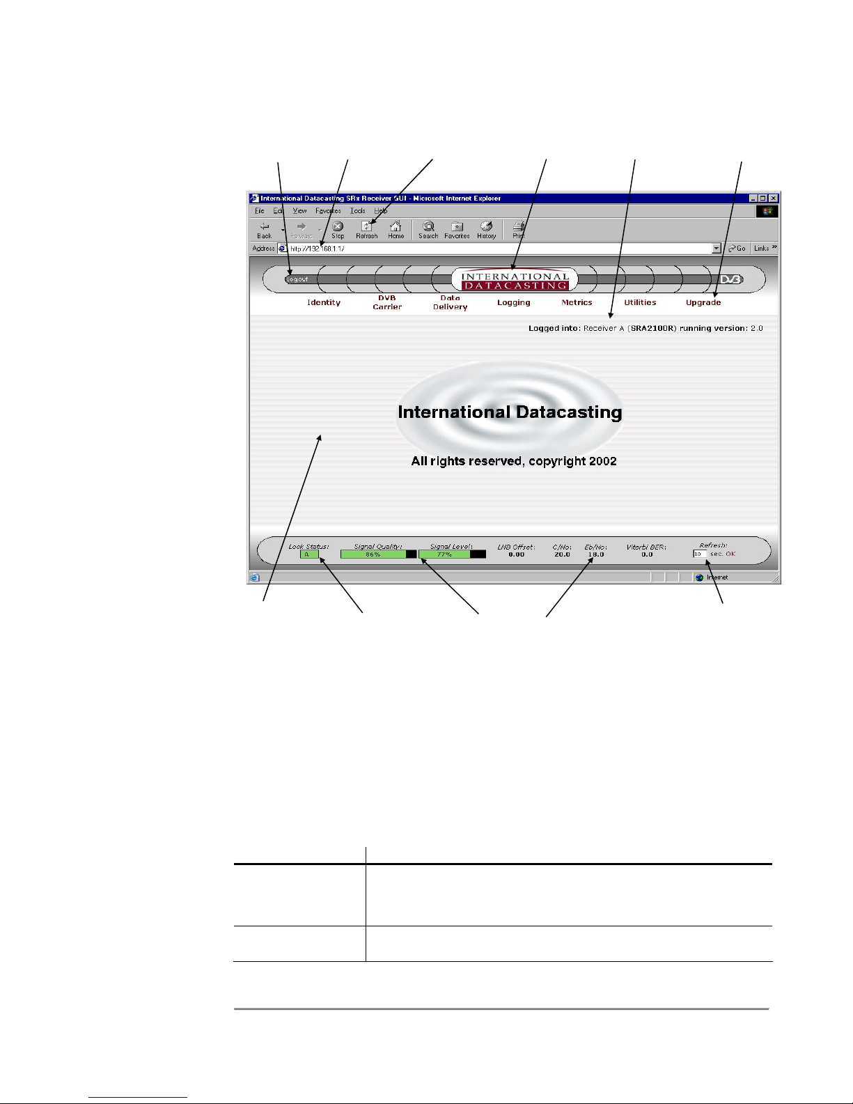
Logout
Icon
SRA/SFX2100 SERIES SATELLITE RECEIVER
Receiver
IP Address
Browser
Refresh Button
IDC Logo
www.intldata.ca
Receiver
Identity
Main Menu
Tool Bar Area
Main
Display
Area
DVB Carrier A/B
Lock Status
Display Area
RF Metrics
RF Metrics
Refresh Rate
Selection
Figure 4-1 Main Menu Page with Identified Areas
Main Menu Tool Bar Area
The Main Menu Tool Bar presents all the main menu options available with this receiver.
This area remains displayed at all times and you can click on any of the tool bar options at
any time to return to a known location in the menu structure. The following main options are
available:
Tool Bar Option Description
Identity Items associated with displaying and/or editing the identity of
the receiver, including name, MAC Addresses, IP addresses,
DHCP enable, etc.
DVB Carrier Items associated with the RF tuner/demodulator setup of the
satellite receiver, including DVB Carrier A/B setup and LNB
32

SRA/SFX2100 SERIES SATELLITE RECEIVER
Tool Bar Option Description
attributes.
Data Delivery Items associated with all data delivery to/from the receiver,
including PID definitions, multicast and unicast routing, NAT,
IGMP, Firewalling, etc.
XD Suite (SFX
only)
Items associated with the configuration of the XD client
application in the SFX2100.
Player (SFX only) Items associated with the configuration of the video/audio
streaming and file player applications in the SFX2100.
Logging Items associated with local and remote status logging of
receiver events, including RF status and faults.
Metrics Items associated with RF and data metrics displays.
Utilities Items associated with peripheral utilities required to properly
operate the receiver in your network, including Date/Time,
Passwords, Ping, etc.
Upgrade Items associated with the upgrade of application firmware and
other software applications required to properly operate the
receiver.
Documents (SFX
only)
Area where the online User documentation can be stored on an
SFX2100.
Each of these options with their associated submenu items will be described in detail later in
this chapter.
Main Display Area
NOTE:
Displays updates
in the Main Display
Area are not
affected by the RF
Metrics Refresh
Rate. If you wish
to update content
in this area at any
time, you must use
the Browser
Refresh Button.
The Main Display Area provides all the dynamic display information for a given menu
option. All submenu items and associated status displays, tables, and edit pages are
displayed in this area. Best viewing is achieved with a browser running on a PC set for
1024 x 768 resolution or higher. The lowest resolution is 800 x 600, and all Web GUI pages
have been designed to display all possible submenu options with this resolution, however,
you may find that you will need to use scroll bars more often than when the resolution is set
higher.
DVB Carrier A/B Lock Status
The DVB Carrier A/B Lock Status provides an updated lock status of the DVB carrier being
currently received. This area remains displayed at all times and indicates that the receiver
is locked to carrier A or B using a green square with the A or B letter inside. If the receiver
is not locked to a carrier, the lock status will be indicated with a red square. This display
area is updated at the periodic refresh rate set by the RF Metrics Refresh Rate (in
seconds).
33

SRA/SFX2100 SERIES SATELLITE RECEIVER
RF Metrics Display Area
The RF Metrics Display Area presents an updated RF status of the DVB carrier being
currently received. This area remains displayed at all times and metrics information
presented here is only valid if the DVB Carrier A/B Lock Status indicates that the receiver is
locked to carrier A or B (green square). This display area is updated at the periodic refresh
rate set by the RF Metrics Refresh Rate (in seconds). The following metrics are displayed:
Metric Description
Signal Quality This display gives an indication of the Quality of the incoming
data stream. This feature is useful to evaluate the quality of the
incoming RF signal. A value from 0% to 100% is shown within
the display. The higher the percentage, the better the Carrier To
Noise (C/No) or quality of the digital carrier. This display is
based on an estimation of incoming noise by the receiver front
end and is accurate to ± 10%.
The display bar changes colour, according to the following:
Black – receiver is not locked to a carrier.
Red – signal quality is too low (1% to 24%).
Green – signal quality is in acceptable operating range (25% to
100%).
Signal Level This display provides a percentage of the signal strength of the
DVB carrier that is being received at the L-Band input to the
receiver.
The display bar changes colour, according to the following:
Black – receiver is not locked to a carrier.
Red – signal level is too low (1% to 19%) or too high (90% to
100%).
Yellow – signal level is marginally too low (20% to 29%) or
marginally too high (80% to 89%).
Green – signal level is in the acceptable AGC operating range
(30% to 80%).
LNB Offset This indicates what the current LNB offset is, based on the
automatic LNB drift tracking mechanism of the receiver. This
value is added or subtracted from the set frequency in the DVB
Carrier definition to tune to the carrier.
C/No This value represents the estimated carrier to noise ratio (in dB)
at the L-Band input to the receiver. The format of this value is
x.y dB.
Eb/No This value represents the calculated Eb/No (in dB) at the input
to the receiver. This value is derived from the C/No value, with
compensation for modulation scheme, reed-solomon FEC,
viterbi FEC rate, and symbol rate of the carrier.
Viterbi BER This is the number of bit errors encountered during a fixed frame
length of incoming data. This data is obtained from the receiver
34

SRA/SFX2100 SERIES SATELLITE RECEIVER
Metric Description
demodulator chip, and is converted to a BER value in the form
x.y E -z.
The accuracy of the values reported for C/No and Eb/No are typically ±1 dB up to a C/No of
15 dB (BER of 1 x 10
-12
). With C/No values higher than 15 dB, the accuracy degrades. (A
DVB signal can be considered error free at greater than 7 dB Eb/No at 7/8 Viterbi, 4 dB
Eb/No at 1/2 Viterbi).
All RF metrics are accurate to the above-mentioned limits, when AFC is set to Fast
Acquisition mode. Performance Mode is recommended for use when large adjacent
carriers are present. The presence of these adjacent carriers affects the C/No estimation
circuitry, with the result that the accuracy of the RF metrics may change. Since the
presence, type and strength of adjacent carriers are site specific, it is not possible to provide
accurate C/No and Eb/No estimation in a general way. It is also difficult to determine what
accuracy there would be with adjacent carriers present, or whether the accuracy would be
any less than that stated above.
RF Metrics Refresh Rate Selection
This area allows you to specify what the refresh rate will be in seconds, for updates to the
metrics displayed in the RF Metrics Display Area. Enter a value between 1 and 99, and
click on the OK word to the right. This will cause the Web GUI to immediately provide the
RF Metrics information to the browser at the specified period in seconds.
Main Menu Tool Bar
The Main Menu Tool Bar provides the top-level menu access for all functions that can be
monitored and controlled in the receiver. The remainder of this chapter will describe these
functions, as organized by menu items, shown in the following menu hierarchy:
Main Menu
Identity
DVB Carrier
Data Delivery PIDs and Ports NET PIDs
DVB Carriers
LNB Attributes
Show
Edit
Back to Main
Cancel Changes
Send Update
Carrier Status
Edit Carrier A
Edit Carrier B
Back to Main
Cancel Changes
Send Update
Show Attributes
Edit
Reset LNB Offset
Back to Main
Cancel Changes
Send Update
ASYNC PIDs
SYNC PIDs
Other PIDs
35

SRA/SFX2100 SERIES SATELLITE RECEIVER
Edit Selected
Add New PID Definition
Delete Selected
Delete ALL
Back to Main
Cancel Changes
Send Update
Show IGMP Net1 (eth0)
Show IGMP Net2 (eth1)
Edit IGMP Net1 (eth0)
Edit IGMP Net2 (eth1)
Restore Net1 (eth0) defaults
Restore Net2 (eth1) defaults
Back to Main
Cancel Changes
Send Update
Show Table
Edit Table
Back to Main
Cancel Changes
Send Update
Show Table
Edit Default Route
Edit Table
Back to Main
Cancel Changes
Send Update
Show SNAT Table
Edit Default Rule
Edit SNAT Table
Back to Main
Cancel Changes
Send Update
Show DNAT Table
Edit Default Rule
Edit DNAT Table
Back to Main
Cancel Changes
Send Update
Show Filtering Table
Edit Default Rule
Edit Filtering Table
Back to Main
Cancel Changes
Send Update
Show Firewall Table
Edit Default Rule
Edit Firewall Table
Back to Main
Cancel Changes
Send Update
Show TTL Table
Edit TTL Table
Back to Main
Cancel Changes
Send Update
Show Log
Edit
Back to Main
Cancel Changes
Send Update
Logging
IGMP
Static Routing
Multicast Routing
Source NAT
Destination NAT
Filtering
Firewall
TTL Translation
36

SRA/SFX2100 SERIES SATELLITE RECEIVER
Metrics
Utilities
Upgrade Back to Main
Show RF & PID Metrics
Back to Main
Date and Time
Password Manager
Ping Utility
Restart Receiver Back to Main
GUI Server Setup Show Server Configuration
Back to Main
Show System Health Metrics
Show Interface Metrics
Show Filtering Metrics
Edit Refresh Interval
Edit RF Metrics Logging Interval
Cancel Changes
Send Update
Show
Edit
Back to Main
Cancel Changes
Send Update
User: admin
User: user
User: monitor
Back to Main
Cancel Changes
Change Password
Back to Main
Cancel Changes
PING
RESTART
Edit Server Configuration
Cancel Changes
Send Update
Cancel Changes
Upgrade
The Action of the Mouse
A standard web browser interface is used for most of the pages and tables in the Web GUI.
In general, moving the mouse over an active icon or menu item and clicking the left mouse
button will select that item. In the case of data entry into tables, etc., simply place the
mouse cursor in the field you wish to edit and left click to select the field for data entry.
Common Menu Items
Referring to the menu hierarchy in the previous section, you can see at the lowest level that
there are three menu items that basically repeat themselves throughout. These three items
perform the following:
Menu Item Description
Back to Main No matter where you are, selecting this button will always return
you back to the Main Menu page, as shown in Figure 4-1.
Cancel Changes When working in an edit page, selecting this button will cancel
any edits that have been made on that edit page and return you
back to the display page.
37

SRA/SFX2100 SERIES SATELLITE RECEIVER
Menu Item Description
Send Update
(or an action)
This third button is always an action button associated with
sending of updates/edits to the receiver. Selecting this button
will always result in some immediate action taken by the
receiver. Usually, the action will be an update to the receiver’s
configuration.
Drop-down Selection Boxes
Many edit pages utilize drop-down selection boxes, as shown in the example in Figure 4-2.
Clicking on the arrow to the right of the current selection in the box causes the current
selection, and all other available items to be shown. The dotted line is used to separate the
current selection from all items available. If you move the mouse over the item you are
interested in and click the left mouse button, the item will be selected as the new current
selection. Clicking on the current selection or the dotted line always keeps the current
selection. If the dotted line is selected, it will be shown in the box, but the current selection
will still be valid (ie. no change in the current selection).
Current
Selection
Click here to activate
drop-down box
Selecting the dashes is
the same as selecting
1200 in this example
Drop-down Box
List of available items –
select and click on an
item to make it the
Current Selection
Figure 4-2 Drop-down Selection Box
38

SRA/SFX2100 SERIES SATELLITE RECEIVER
Identity
When the Identity Main Menu Tool Bar item is selected, the Identity page is displayed,
which provides information relating to the identification of the receiver on the network, as
well as the current running version of the receiver application firmware and any deviations
(patches) to the firmware and options installed. A sample page is shown in Figure 4-3.
Figure 4-3 Identity Page
Aside from the Common Menu Items, the following menu items are available:
Menu Item Description
Show Selecting this button will always return you back to the Identity
page, as shown in Figure 4-3.
Edit Selecting this button will enter the Identity Edit page, as shown
in Figure 4-4.
When the Edit menu item is selected, the Identity Edit page will be displayed, as shown by
the sample page in Figure 4-4. Each edit field is described after the figure.
39

SRA/SFX2100 SERIES SATELLITE RECEIVER
NOTE:
The MAC Address
of each network
interface is factory
set and cannot be
changed.
Figure 4-4 Identity Edit Page
The following fields can be edited on the Identity Edit page:
Edit Field Description
Name A meaningful name for the receiver can be entered in this field.
Up to 31 characters can be entered. This name will appear on
the Main Menu page in the Receiver Identity area, as well as on
the login page.
Description A meaningful description of the receiver can be entered in this
field. Up to 31 characters can be entered. This description
information supplements the name given to the receiver, and
only appears when the Identity page is displayed.
IP (Address) The IP address of the associated network interface, in dotted
decimal notation (e.g. 192.168.0.1). Each IP address must be
unique and should be on a different subnet.
The network interface can be one of net1 (first Ethernet port
eth0), net2 (second Ethernet port eth1), or sat (satellite receiver
interface sat0).
Unless default IP addresses have been specifically requested,
the factory default IP addresses are: 192.168.0.1 for the Net1
(eth0) interface, 192.168.1.1 for the Net2 (eth1) interface, and
aa.bb.cc.dd for the satellite (sat0) interface.
Netmask The Netmask of the receiver in dotted decimal notation (e.g.
255.255.255.0).
40

SRA/SFX2100 SERIES SATELLITE RECEIVER
Edit Field Description
The factory default netmask is 255.255.255.0.
DHCP Indicates whether DHCP is enabled or disabled.
Dynamic Host Configuration Protocol (DHCP – RFC 2131) is a
communications protocol that allows Network Administrators to
centrally manage and automate the assignment of Internet Protocol
(IP) configuration, including IP address, subnet mask and default
gateway (see Static Routing menu item) for Local Area Network
(LAN) hosts in an organization’s LAN.
In order for a host, such as an SRA or SFX receiver, to connect to
an organization’s LAN, a unique IP address must be assigned to it.
Without DHCP, the IP configuration must be manually entered using
the edit fields described above. However, if a host has moved to
another point on the network, a new IP configuration may have to be
assigned. DHCP lets a Network Administrator distribute IP
configuration from a central point and automatically reconfigures a
host when it is plugged into a different network.
If DHCP has been enabled for a network interface, the IP and
Netmask fields will be ignored.
Default Gateway
DNS
If required, the IP address of the associated default gateway and
the Domain Name Server (DNS), in dotted decimal notation (e.g.
192.168.0.1)
41

SRA/SFX2100 SERIES SATELLITE RECEIVER
DVB Carrier
When the DVB Carrier Menu Tool Bar item is selected, a submenu page appears which
provides menu items relating to the setup and maintenance of the incoming satellite feed
(RF carriers and LNB). These are described in the following sections.
DVB Carrier Definitions
This submenu allows you to set the parameters for the 2 DVB Carriers, which can be
received by the RF front end. The DVB Carrier Status page similar to Figure 4-5 will be
displayed when the DVB Carrier Definitions submenu item is selected. The meaning of
each carrier parameter is explained under the Carrier Edit page. In this example, the
receiver is locked to the 8.57 Ms/s QPSK Carrier A at 1350 MHz.
Aside from the Common Menu Items, the following menu items are available:
NOTE:
The carrier lock
status is not
automatically
updated on the
status page. You
must use the
refresh button on
your browser to
update the lock
status.
Menu Item Description
Carrier Status Selecting this button will always return you back to the DVB
Edit Carrier <X> Selecting this button will enter the Carrier Edit page for the DVB
Copy Carrier <X> These buttons allow you to copy the entire configuration of
Figure 4-5 DVB Carrier Status Page
Carrier Status page, as shown in Figure 4-5. The current status
of both carrier A and B will always be displayed. The carrier that
the receiver is locked to will have its title displayed in green
letters and a message below the title will appear (see example
in Figure 4-4).
Carrier selected, as shown in Figure 4-6.
42
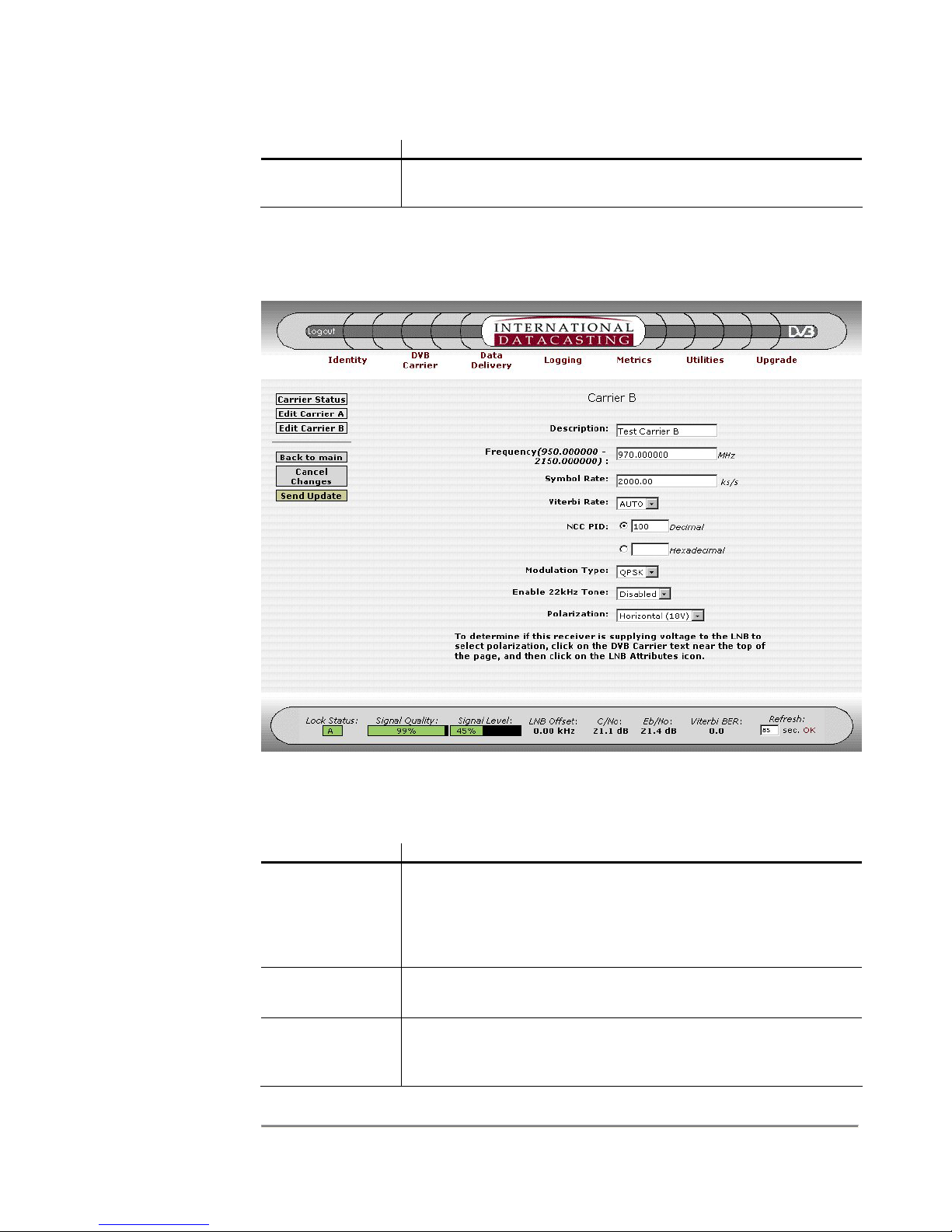
NOTE:
If only one carrier
is being used in
the network, both
Carrier A and B
should be set to
that carrier. This
will reduce the
lock time because
the receiver does
not have to check
for two different
carriers.
SRA/SFX2100 SERIES SATELLITE RECEIVER
Menu Item Description
to Carrier <Y> Carrier to Carrier B, or visa versa. Pressing these buttons saves
you the time of having to enter the same information twice.
When the Edit Carrier <X> menu item is selected, the Carrier Edit page will be displayed, as
shown by the sample page in Figure 4-6 for Carrier B. Each edit field is described after the
figure.
NOTE:
The carrier
symbol rate
includes all
applied FEC
and must be
an exact
value.
Figure 4-6 Carrier Edit Page (Carrier B)
The following fields can be edited on the Carrier Edit page:
Edit Field Description
Description A meaningful name or description for the carrier can be entered
in this field. Up to 31 characters can be entered. This name will
appear on the DVB Carrier page where the carrier status is
provided. If a description is not specified, the word Empty will
be displayed on the DVB Carrier page.
Frequency Is the L-Band receive frequency of the carrier in Hz, in the
numeric range 950000000 - 2150000000 Hz.
Symbol Rate Is the symbol rate of the carrier in symbols per second, in the
numeric range 1000000 - 45000000 S/s for earlier models of
receivers, and 256000 - 45000000 S/s for later models.
43

SRA/SFX2100 SERIES SATELLITE RECEIVER
Edit Field Description
Viterbi Rate Select the Viterbi FEC rate of the carrier, using one of the options:
Auto, 1/2, 2/3, 3/4, 5/6, 7/8, 8/9 (if 8PSK/16QAM option is used).
The following Viterbi FEC/Modulation Type combinations are
possible (in accordance with DVB specifications):
1. Auto Detect (all Modulation Types)
2. 1/2 (QPSK, BPSK only)
3. 2/3 (QPSK, BPSK, 8PSK only)
4. 3/4 (QPSK, BPSK, 16QAM only)
5. 5/6 (QPSK, BPSK, 8PSK only)
6. 7/8 (QPSK, BPSK, 16QAM only)
7. 8/9 (8PSK only)
NCC PID Is the PID number of the NCC PID (in hex), in the numeric range
0x20 to 0x1FFE. Specifying 0 disables the NCC PID.
Modulation Type Select the modulation type, using one of the options: QPSK; or
BPSK, or 8PSK and 16QAM if your model is equipped with this
option.
NOTE:
The Polarization
only selects the
LNB output
voltage. To turn
the LNB power on
or off, you must
use the Supply
Select item, under
the LNB Attributes
submenu.
Enable 22kHz
Tone
Enables or disables the 22 kHz tone to the LNB. The 22 kHz
tone is used to select the L-Band frequency band for output by
the LNB, where Disabled (off) selects 950 to 1950 MHz, and
Enabled (on) selects 1100 MHz to 2150 MHz.
Polarization Is the polarization of the LNB, and sets the output DC voltage
from the receiver to the LNB, using one of the options: h for
horizontal (18VDC standard or 15 VDC optional) and v for
vertical (13VDC standard or 11 VDC optional).
44
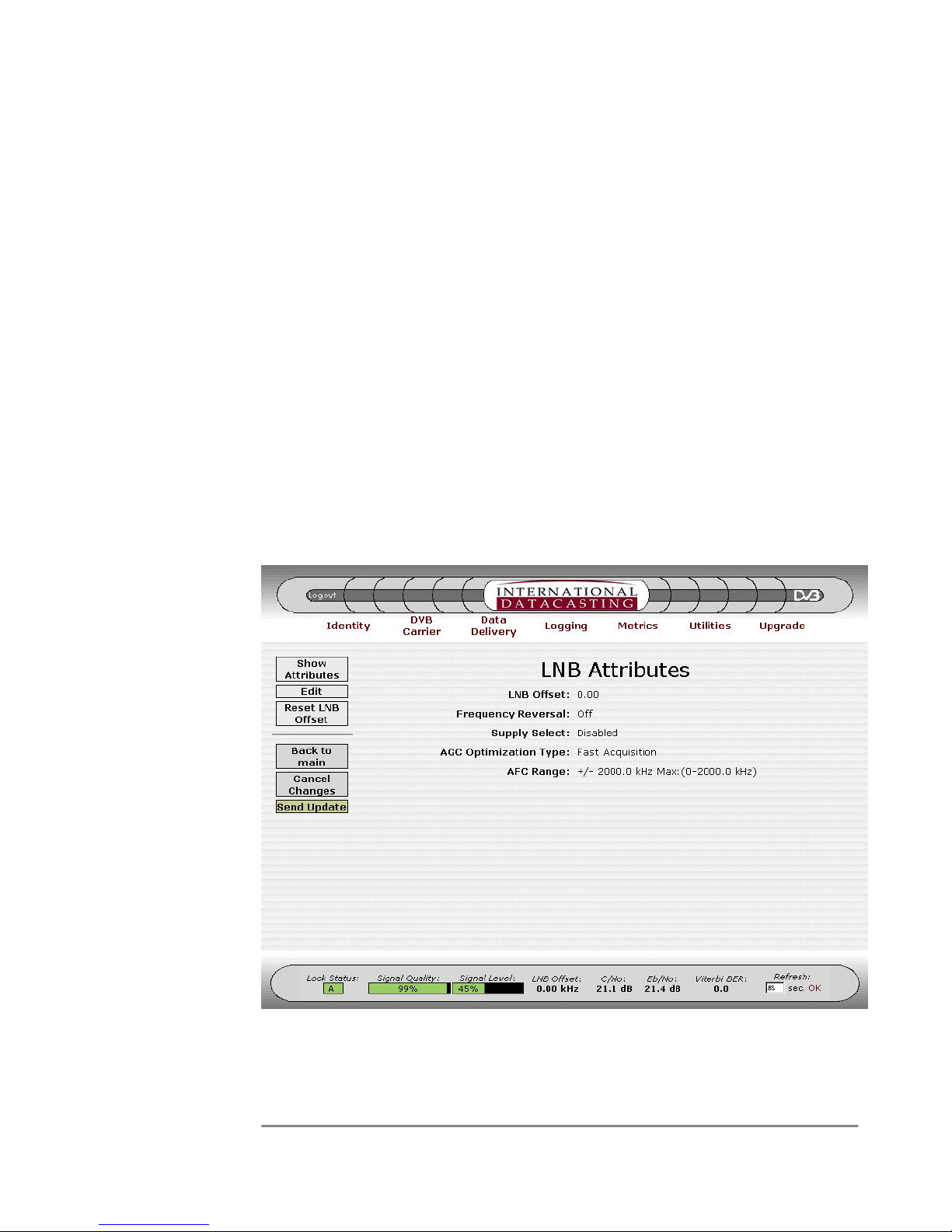
SRA/SFX2100 SERIES SATELLITE RECEIVER
LNB Attributes
This submenu allows you to set the parameters for controlling the LNB. All LNB attributes
are common to both DVB Carriers. The LNB Attributes page similar to Figure 4-7 will be
displayed when the LNB Attributes submenu item is selected. The meaning of each
attribute is explained under the Edit LNB Attributes page.
(The LNB Offset)
On the LNB Attributes page, the LNB offset is updated to the current value whenever the
page is updated (either through menu selection or browser refresh). The LNB Offset that is
displayed is the stored frequency offset in kHz between the frequency set by the user (in the
DVB Carrier Definitions) and the actual frequency that the receiver is locked to. Every 10
seconds, the receiver calculates the difference between the set frequency and the
frequency being used by the RF front-end demodulator when it acquired lock. If the
difference is greater than five percent of the symbol rate, this difference is added to the
accumulated drift. If the accumulated drift is greater than 1.5 MHz (1500 kHz), it is stored
as a positive or negative LNB Offset, which is then displayed on the GUI on both the metrics
area at the bottom of the screen, and the LNB Attributes page on refresh. On startup or
during carrier lock, the receiver is tuned at the set frequency plus this LNB offset. This LNB
Offset can be reset to 0.0.
NOTE:
The LNB Offset is
not automatically
updated on the
LNB Attributes
page. You must
use the refresh
button on your
browser to update
the LNB Offset.
Figure 4-7 LNB Attributes Page
45

SRA/SFX2100 SERIES SATELLITE RECEIVER
Aside from the Common Menu Items, the following menu items are available:
Menu Item Description
Show
Attributes
Selecting this button will always return you back to the LNB
Attributes page, as shown in Figure 4-7. The current LNB offset
value in kHz is displayed, as calculated by the receiver as it
compensates for LNB drift.
Edit Selecting this button will enter the Edit LNB Attributes page, as
shown in Figure 4-8.
NOTE:
The LNB
Attributes are
applicable to
both DVB
Carriers.
Reset LNB
Offset
This will reset the receiver’s internal LNB drift tracking offset
frequency back to 0.0 kHz.
The following fields can be edited on the Edit LNB Attributes page:
Edit Field Description
Frequency
Reversal
Figure 4-8 Edit LNB Attributes Page
Enables or disables LNB frequency reversal. Off is the default.
Frequency reversal permits the use of other LNB variants that may
use low side Local Oscillators (LOs) instead of high side LOs. The
use of LNBs such as older C-Band type with low side LOs can
cause spectral inversion, and this feature can make the LNB appear
46

SRA/SFX2100 SERIES SATELLITE RECEIVER
Edit Field Description
“normal” when setting the L-Band frequency of the DVB Carrier
using the Carrier Edit <X> page (see previous section).
NOTE:
Supply Select
turns on or off the
LNB power supply
only. The voltage
actually being
output is
determined by the
Polarization setting
in the DVB Carrier
Edit page.
Supply Select Enables or disables the LNB power supply, which supplies DC
voltage to the LNB from the L-Band connector on the rear panel.
When enabled, the DC voltage output will be determined by the
polarization setting from the Carrier Edit <X> page (see previous
section).
AGC
Optimization
The AGC optimization type, using one of the options: performance
mode or fast acquisition mode.
Type
Performance Mode
– this mode forces the receiver to step through
individual gain stages in the Digital Filter to determine the best Bit
Error Rate (BER) performance. This feature should only be used if
there are large adjacent carriers to the DVB Carrier of interest. Lock
acquisition will generally be slower if this mode is selected.
Fast Acquisition Mode
– this mode forces the receiver to select a
default Digital Filter that performs well under most conditions. This
is the default mode and provides the fastest lock acquisition time.
AFC Range The AFC range in Hz, in the numeric range 0 to 2000.0 kHz (0 to 2
MHz), in steps of 0.1 kHz. If this field is not edited, an AFC range of
10% of the carrier symbol rate is default.
47

SRA/SFX2100 SERIES SATELLITE RECEIVER
Data Delivery
When the Data Delivery Tool Bar item is selected, a submenu page appears which
provides menu items relating to the routing, filtering, firewalling, address translation and
output of data on the receiver interfaces. These are described in the following sections.
In order to understand how the various data delivery functions work, you should understand
the path IP packets will take as they are processed by the receiver. This data flow is
demonstrated in the Data Flow Diagram of Figure 4-9. In this flow, IP packets can originate
from two primary sources: the satellite interface (sat0) after PID Filtering and MPE Deencapsulation, or the network (LAN) interfaces.
As shown in Figure 4-9, the receiver processes IP packets that enter, leave, and pass
through it. Basically, there is a chain for each of these paths. Any packet entering the
receiver goes through the PREROUTING and INPUT chains. Any packet that the receiver
sends out to the network goes through the OUTPUT and POSTROUTING chains. Any
packet that the receiver picks up on one network and sends to another goes through the
FORWARD chain.
Many of the menu items available under Data Delivery maintain tables that allow you to set
up certain rules in each of these chains that decide what happens to packets of data that
pass through them. With every packet, the rules in the appropriate table in the chain are
checked to see if any of them match. The first one that matches will decide the outcome of
that packet. If none of the rules match, then the default rule or policy of the whole chain will
be the final decision maker.
48

SRA/SFX2100 SERIES SATELLITE RECEIVER
(
)
(
)
(GUI Edited Table)
NETWORK
Incoming IP Packets from
other network devices
(eth0, eth1, etc.)
Firewalling
(INPUT)
DVB CARRIER
DVB Packets
PID Filtering
PIDs and Ports
MPE Frame
De-encapsulation
IP Packets from sat0
TTL Translation
PREROUTING
Destination NAT
(PREROUTING)
Input
Routing Decisions
Static Routing,
Multicast Routing,
IGMP
(GUI Edited Table)
(GUI Edited Table)
(GUI Edited Tables)
(GUI Edited Tables)
(Local Process
Controlled Table)
(Local Process
Controlled Table)
(GUI Edited Table)
Local Processes
e.g. XD, Video Streaming,
etc. (mostly in the SFX)
Output
Routing Decisions
Gateways, etc.
TTL Translation
(OUTPUT)
Source NAT
(OUTPUT)
Firewalling
(OUTPUT)
Source NAT
(POSTROUTING)
NETWORK
Filtering
(FORWARD)
(GUI Edited Table)
Figure 4-9 Data Flow Diagram
49

SRA/SFX2100 SERIES SATELLITE RECEIVER
PIDs and Ports
This submenu provides all the functions that allow you to setup the PID filtering for all
relevant data streams in the DVB Transport Stream.
(PID Filtering and PID Types)
Up to 250 PID streams can be filtered by the receiver, regardless of type, however, there
are restrictions on how many PIDs of a type can be assigned to a port. Aside from special
types such as the NetManager NCC PID, there are four types of PIDs, as organized by four
distinct PID Lists:
NOTE:
Up to 250 PID
streams can be
filtered by the
receiver,
regardless of type,
however, there are
restrictions on how
many PIDs of a
type can be
assigned to a port.
Whenever a PID is
inserted into a PID
list, it will use one
PID filter in the
receiver, whether
that PID is enabled
for output or not.
1. Net PIDs
– these are the IP network data streams that are processed by the IP
Stack in the receiver and forwarded either to internal applications that use IP data,
or for output on a network device, such as an Ethernet port. All data in Net PIDs
are encapsulated using Multi-Protocol Encapsulation (MPE). Up to 250 PIDs can
be assigned to the Net PID List, and enabled for output on the network device
port(s), depending on routing, filtering, firewall rules, etc..
If the Cyphercast option is installed in your receiver, then the ECM/EMM PID
required by Cyphercast must be assigned in the Net PID List. This can be done
either directly here, under PIDs and Ports, or in the Cyphercast configuration page.
The Network Control Channel PID is an MPE encapsulated Net type PID as well,
however, it is a special PID, used internally by the receiver to decode NetManager
control commands. It is setup in the DVB Carrier Definitions, and will not appear in
the Net PID List. However, it will use one of the 250 available PID filters, if
enabled.
2. Async PIDs
– these are the data streams that are available for output on the
ASYNC (RS-232) port. All data in an Async PID is encapsulated using MPE as
well. Up to 250 PIDs can be assigned to the Async PID List, but only one PID can
be enabled for output to the ASYNC port at a time.
3. Sync PIDs
- these are the data streams that are available for output on the SYNC
(RS-422) port. All data in a sync PID is encapsulated using a proprietary method
specific to IDC MX series encapsulators. Up to 250 PIDs can be assigned to the
Sync PID List, but only one PID can be enabled for output to the SYNC port at a
time.
4. Other PIDs
applications, such as the ASI Output option. These PIDs do not conform to any
one of the types and rules above and are not routed to one of the standard output
ports.
When the PIDs and Ports submenu item is selected, a PID List is displayed on a page
similar to Figures 4-10 to 4-13. Generally, the Net PID List (Figure 4-10) will be displayed
by default. You can select any other PID list by pressing one of the PID type buttons on the
left of the page (i.e. one of NET PIDs, ASYNC PIDs, SYNC PIDs, and Other PIDs).
– these are PIDs that are filtered and may be used for other
50
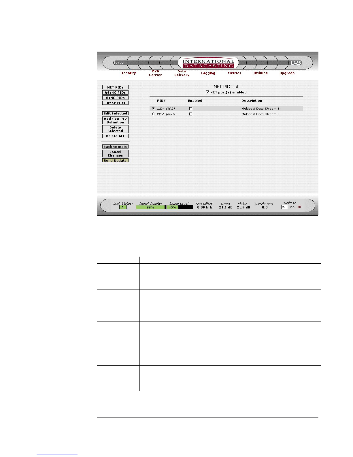
SRA/SFX2100 SERIES SATELLITE RECEIVER
Figure 4-10 Net PID List Page
The display fields and columns in the Net PID List (Figure 4-10) have the following
meaning:
Column/Field Description
NET port(s)
enabled
This is a check box, which is used to enable or disable all network
devices that are capable of IP data output. Generally, this will affect
data output at the Ethernet (NET1/eth0 and NET2/eth1) ports.
Radio Buttons Clicking on the radio button will select a PID in the list. Once
selected, you can use the Edit Selected button to edit the PID
definition, or Delete Selected to delete the PID from the list. Only
one PID can be selected at a time.
PID # This is the numeric value for the PID, displayed in decimal and
hexadecimal in brackets.
Enabled These check boxes authorize each individual PID for output.
Overall, the NET Port(s) enabled check box (see above) has to be
turned on for these check boxes to have any effect.
Description This is a text description of the PID, as entered when the PID was
defined using the Add New PID Definition or Edit Selected menu
items.
51

SRA/SFX2100 SERIES SATELLITE RECEIVER
Aside from the Common Menu Items, the following menu items are available:
Menu Item Description
NET PIDs Selecting this button will always return you back to the Net PID List
page, as shown in the example in Figure 4-10. All PIDs currently
assigned as type Net will be displayed, whether they are enabled for
output on a network device (port) or not.
ASYNC PIDs Selecting this button will always return you back to the Async PID
List, as shown in the example in Figure 4-11. All PIDs currently
assigned as type Async will be displayed, whether they are enabled
for output on the Async port or not.
SYNC PIDs Selecting this button will always return you back to the Sync PID
List, as shown in the example in Figure 4-12. All PIDs currently
assigned as type Sync will be displayed, whether they are enabled
for output on the Sync port or not.
Other PIDs Selecting this button will always return you back to the Other PID
List, as shown in the example in Figure 4-13. All PIDs currently
assigned as type Other will be displayed, whether they are enabled
for output or not.
NOTE:
When you select
the Delete
Selected or Delete
ALL buttons, you
will be disabling
data services at
the output of the
receiver, if the
PID(s) and port
are enabled.
Edit Selected Selecting this button will enter the Edit PID Definition page (see
example in Figure 4-15) for the PID selected in the list (using the
radio button on the left hand side of the list).
Add New PID
Definition
Selecting this button will enter the Add New PID Definition page, as
shown in Figure 4-14. This will add a new PID to the list, so no
selection is required.
Delete
Selected
Selecting this button will remove a selected PID (using the radio
button on the left hand side of the list) from the PID list. PIDs are
deleted whether they are enabled or not.
Delete ALL Selecting this button will remove all PIDs from the PID list. All PIDs
will be deleted whether they were enabled or not.
52

SRA/SFX2100 SERIES SATELLITE RECEIVER
Figure 4-11 Async PID List Page
The display fields and columns in the Async PID List (Figure 4-11) have a similar meaning
to the Net PID List fields and columns, with following exceptions:
Column/Field Description
PID Rate This is the baud rate (bps) that the Async Port will be set to when
the data is output from this PID. Effectively, this is the maximum
data rate for the data received from this PID – it could be received
from the satellite at a slower rate, but will be output from the Async
Port at the baud rate shown.
No PIDs
Enabled
Since only one PID can be assigned to the Async Port at any one
time, the enable column was implemented using radio buttons
instead of check boxes. Radio buttons force a single selection to be
made, so the valid selection of No PIDs Enabled has to be provided,
which means no PIDs are authorized for output on the async port.
53

SRA/SFX2100 SERIES SATELLITE RECEIVER
Figure 4-12 Sync PID List Page
The display fields and columns in the Sync PID List (Figure 4-12) have a similar meaning to
the Async PID List fields and columns, with following exceptions:
Column/Field Description
Inverted X.21
Mode
This selects normal X.21 balanced signals, or inverted X.21
balanced signals for countries where X.21 signals are reversed.
PID Rate This field specifies the output clocking rate of the Sync Port in bits
per second. Allowable values are between 1 and 10000000 bps
inclusive. The actual output rate of the sync port may vary around
this value by up to 10 parts per million to compensate for jitter in the
incoming data.
54

SRA/SFX2100 SERIES SATELLITE RECEIVER
Figure 4-13 Other PID List Page
The display fields and columns in the Other PID List (Figure 4-13) have a similar meaning to
the Net PID List fields and columns, except these are PIDs with no specific port assignment.
Additional columns are added when the ASI Output option is installed, for example. See
the ASI Option appendix for more information.
55

SRA/SFX2100 SERIES SATELLITE RECEIVER
NOTE:
For ports where
only 1 PID can be
output at a time
(e.g. Async and
Sync), use caution
when enabling a
new PID and
pressing Send
Update. Doing so
will disable any PID
already enabled for
that port.
Figure 4-14 Add New PID Definition Page
The Add New PID Definition page allows you to define a new PID, of any type based on the
destination port (Net, Async, Sync, Other). Once the Send Update has occurred, the PID
will be placed in appropriate PID List, based on its type. The following fields can be edited
on the Add New PID Definition page:
Edit Field Description
PID # The PID number in the decimal range 32 to 8190, or hexadecimal
range 0x20 to 0x1FFE, must be entered here.
Enabled Selecting this check box will enable or disable the PID for output.
PID Type The radio buttons allow you to select one type, based on the desired
destination port for data output. This selection determines which
PID List will “own” the PID.
The Async Port and Sync Port require a data rate to be entered:
• Async data rates are the standard RS-232 port baud rates: 300,
1200, 2400, 4800, 9600, 19200, 38400, 57600, and 115200
bps.
• Sync data rates can be entered in the range 1 to 10000000 bps.
56

SRA/SFX2100 SERIES SATELLITE RECEIVER
Edit Field Description
Description A meaningful name or description for the PID can be entered in this
field. Up to 31 characters can be entered. This name will appear on
the PID List page where the PID information is provided. If a
description is not specified, the field will display nothing.
Figure 4-15 Edit PID Definition Page
The Edit PID Definition page (example in Figure 4-15) allows you to edit a current PID
definition, of a PID selected from one of the PID Lists (Net, Async, Sync, Other). The fields
have the same meaning as the Add New PID Definition page. Once the Send Update has
occurred, the PID will be updated in appropriate PID List, based on its type. You can
change a PID type from this page. Doing so will move the PID from its current PID List to a
new PID List.
57

SRA/SFX2100 SERIES SATELLITE RECEIVER
IGMP
The Internet Group Management Protocol (IGMP V2 – RFC 2236) is an Internet Protocol
that provides the means for a computer to report its multicast group membership to
adjacent routers, allowing it to “tune-in” to multicast transmissions destined for that group.
IP Multicasting allows a host receiver to send content to one or more other computers that
have identified themselves as being interested in receiving that content, known as a
multicast group. Multicasting can be used for such applications as broadcasting streaming
media, sending course content in distance learning applications, or delivering financial
information to branch offices in enterprise applications.
IGMP operates in networks where the receiver is directly connected to the subnet. The
receiver issues IGMP queries and receives IGMP membership reports directly.
When the IGMP submenu item is selected under Data Delivery, the IGMP page is
displayed for a selected Ethernet network interface. A sample page is shown in Figure 4-16
for the Net1 (eth0) Ethernet interface.
Aside from the Common Menu Items, the following menu items are available:
Menu Item Description
Show IGMP
<interface>
Figure 4-16 IGMP Page for Net1
Selecting this button will always return you back to the IGMP page
for the selected Ethernet network interface, as shown in Figure 4-16.
58
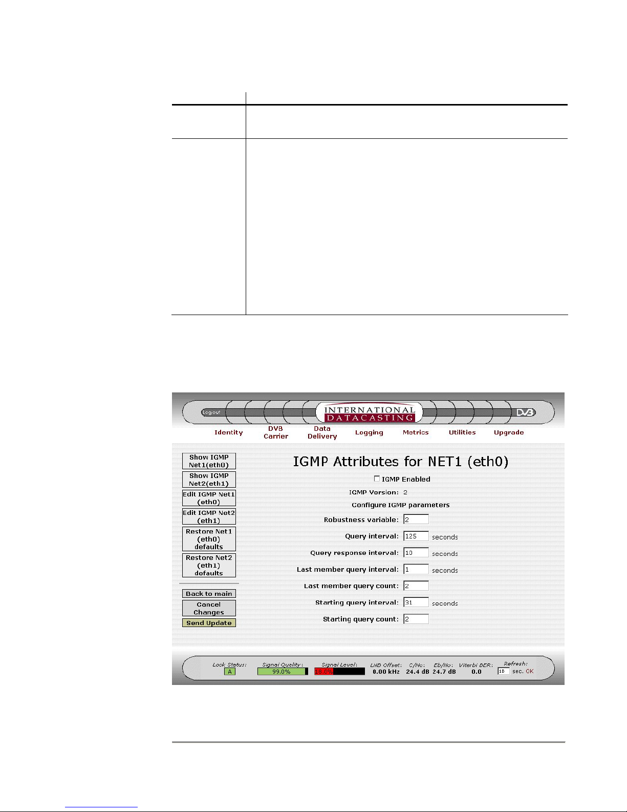
SRA/SFX2100 SERIES SATELLITE RECEIVER
Menu Item Description
Edit IGMP
<interface>
Selecting this button will enter the IGMP Edit page, as shown in
Figure 4-17, for the selected Ethernet network interface.
Restore
<interface>
Defaults
Selecting this button will enter the IGMP Edit page, but with factory
default values inserted into the edit fields automatically. You may
then wish to edit these values, in the same manner used when the
Edit IGMP buttons were pressed.
The following default values are inserted:
IGMP Disabled (pass all multicast packets out the network interface)
Robustness Variable = 2.
Query Interval = 125 seconds.
Query Response Interval = 10 seconds.
Last Member Query Interval = 1 seconds.
Last Member Query Count = 2.
Starting Query Interval = 31 seconds.
Starting Query Count = 2.
The individual IGMP variables displayed are explained with the IGMP Edit page. When the
Edit menu item is selected, the IGMP Edit page will be displayed, as shown by the sample
page in Figure 4-17. Each edit field is described after the figure.
Figure 4-17 IGMP Edit Page
59

SRA/SFX2100 SERIES SATELLITE RECEIVER
The following fields can be edited on the IGMP Edit page:
Edit Field Description
IGMP Enabled A check in this field enables or disables IGMP support. If
IGMP is disabled, the receiver outputs all multicast packets.
Robustness Variable This field is related to the expected packet loss on the
subnet. IGMP is robust to (Robustness Variable – 1) packet
losses. The default value is 2.
Query Interval This field sets the frequency at which General Queries are
sent out on the LAN, via the Ethernet interface. The default
value is 125 seconds.
Query Response
Interval
Last Member Query
Interval
This field sets the amount of time a node on the LAN has to
respond to an IGMP query. The default value is 10 seconds.
This field sets the maximum response time to a GroupSpecific Query that is sent after a Leave Group Message is
received from a node on the LAN. The default value is 1
second.
Last Member Query
Count
This field sets the number of Group-Specific Queries that are
sent out in response to a Leave Group Message. The
default value is equal to the Robustness Variable value.
Startup Query Interval This field sets the frequency at which queries are sent out on
startup of a multicast transmission. The default value is ¼
of the Query Interval.
Startup Query Count This field sets the number of queries sent out on startup,
using the Startup Query Interval. The default value is equal
to the Robustness Variable.
60

SRA/SFX2100 SERIES SATELLITE RECEIVER
Static Routing
The Static Routing submenu maintains the static routing table associated with the receiver.
Each receiver can support up to 32 static routes. The routing subsystem determines where
outgoing unicast IP packets are sent and applies to all IP packets, regardless of the network
interface they originated from.
Static unicast routing is done using the Linux Route facility. Additional information can be
obtained online with the manual at sites such as http://www.linuxcentral.com
Pages, Administrative and Privileged commands). Additionally, you can contact IDC
Customer Service for additional information (see Chapter 5).
Packets are routed according to the following rules:
1. IP packets can originate from any of the available network interfaces and are
processed by the receiver in accordance with the data flow in Figure 4-9.
2. Routes may be entered in any order and allow IP packets to be routed out a
gateway, according to the destination address and netmask.
3. Packets addressed to a device on a receiver subnet are sent out on the applicable
physical network to which the receiver is attached.
(Linux Man
4. Packets addressed to the global (i.e. limited) broadcast address are sent out on all
the applicable physical networks to which the receiver is attached.
5. Packets addressed to the receiver’s subnet broadcast address are sent out on the
applicable physical network to which the receiver is attached.
6. Multicast packets are sent out on the physical network in accordance with the
Multicast Routing rules (see Multicast Routing section).
7. Packets addressed to other subnets are sent to the appropriate gateway as
defined in the routing table.
8. All packets that cannot be sent out using the rules described above (1-7) are
discarded by the receiver.
9. An entry that has its Network Address and Netmask both set to 0.0.0.0 will
represent a Default Gateway, and only one such entry will be allowed in the
receiver. This Default Gateway will be the same as the Default Gateway
displayed on the Identity page (see Figure 4-3).
10. The Destination Address, Netmask, and Gateway entries must be expressed in
dotted decimal notation.
11. The Gateway Address cannot be a loopback, broadcast, or multicast address and
must be on the same subnet as the receiver. However, it cannot be the receiver’s
IP address.
12. The Network Address cannot be a loopback, broadcast or multicast address, and
cannot be on the same subnet as the receiver.
61

SRA/SFX2100 SERIES SATELLITE RECEIVER
When the Static Routing submenu item is selected under Data Delivery, the Static Routing
page is displayed for all network interfaces, including the optional modem interface, if the
Modem Option is installed. A sample Static Routing page is shown in Figure 4-18.
Figure 4-18 Static Routing Page
The columns in the Static Routing page are described under the Edit Routing Table page
(Figure 4-19), with the following exceptions:
Column Description
To Edit, Go
To:
The routing table displays all static routes from all network interfaces
in the receiver, including optional interfaces such as the
modem/PPP interface. Some of the routes associated with these
interfaces are configured with other GUI edit pages besides the Edit
Table page here. This column tells you where you must edit the
configuration. In the example in Figure 4-18, the second entry in the
table is edited using the Identity Edit page (see Figure 4-4). The
words “Edit Table” appear if the route can be edited locally.
Destination For locally configured routes, this field corresponds to the
Destination entered in the Routing Table Edit page (Figure 4-19).
For routes established elsewhere (Identity Edit page for example),
the destination is the subnet derived from the IP Address and
Netmask of the associated network interface.
62
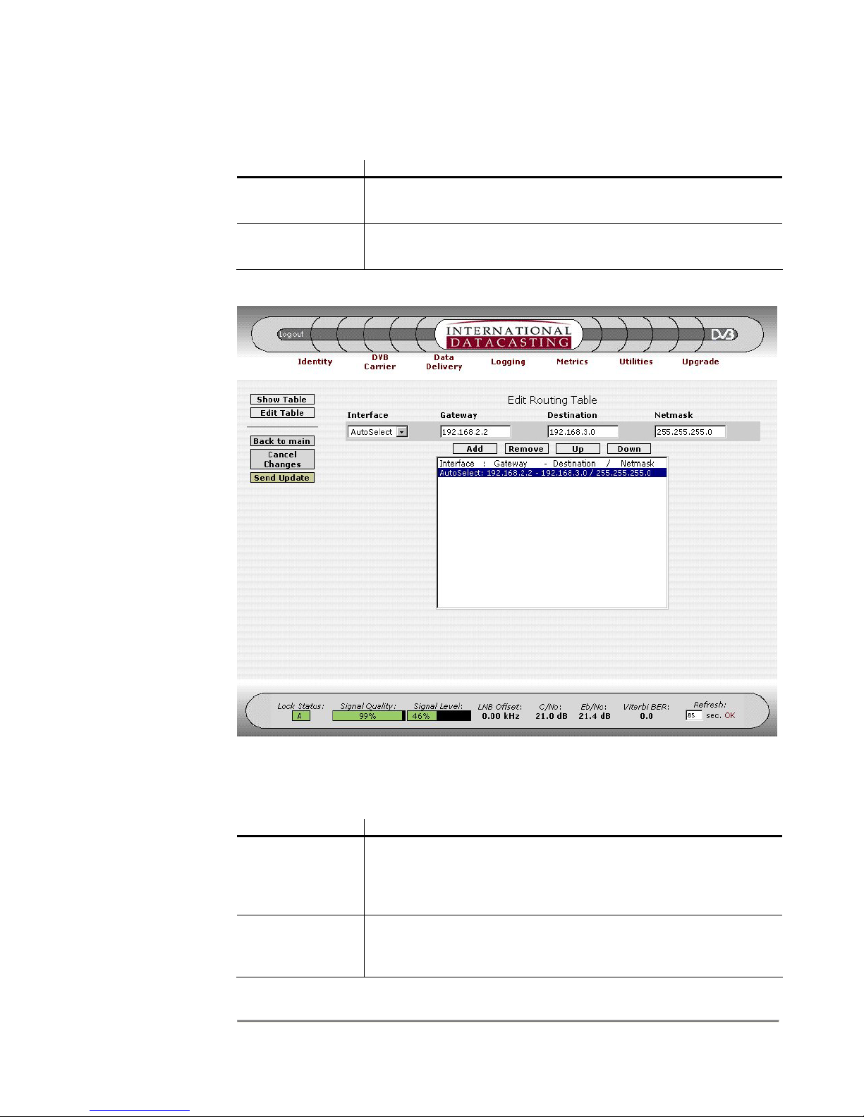
SRA/SFX2100 SERIES SATELLITE RECEIVER
Aside from the Common Menu Items, the following menu items are available:
Menu Item Description
Show Table Selecting this button will always return you back to the Static
Routing page, as shown in Figure 4-18.
Edit Table Selecting this button will enter the Edit Routing Table page, as
shown in Figure 4-19.
The following fields can be edited on the Edit Routing Table page:
Edit Field Description
Interface This drop down box selects the network interface that is
Gateway A valid gateway address in dotted IP address notation is entered
Figure 4-19 Edit Routing Table Page
applicable to the route. In most typical routing configurations,
you want this to remain on AutoSelect, which allows any
interface to be applicable.
here, according to the rules above. An address of 0.0.0.0
implies that there is no gateway.
63

SRA/SFX2100 SERIES SATELLITE RECEIVER
Edit Field Description
Destination Enter a destination IP Address in dotted decimal notation,
according to the rules above.
Netmask To define the applied network, enter a Netmask in dotted
decimal notation, according to the rules above.
In addition to the edit fields there are four table row manipulation keys:
Key Description
Add Add the entered information above the table to the table as the
last row.
Remove Delete the selected (highlighted) row.
Up If there is more than one row in the table, move the selected row
up one row.
Down If there is more than one row in the table, move the selected row
down one row.
64

SRA/SFX2100 SERIES SATELLITE RECEIVER
Multicast Routing
The Multicast Routing submenu maintains the multicasting routing table associated with the
receiver. Each receiver can support up to 200 multicast routes. The multicast routing
function is responsible for managing multicast packets that are traveling through the
receiver (host), from external interface to external interface. It is not responsible for
managing multicast packets that are delivered to an application running on the receiver, but
the two functions are inter-related.
Multicast packets are routed through the host according to a multicast routing table that is
maintained by the Linux kernel. Initially, this table is empty and incoming multicast packets
are routed according to a default route.
Multicast Routing follows a number of rules, as described in the list below. Many rules are
best described by examples. Many of these rules are more important in the SFX series
receiver, where a number of local applications may be consuming multicast packets (e.g.
streaming media decoder).
1. IP packets can originate from any of the available network interfaces and are
processed by the receiver in accordance with the data flow in Figure 4-9.
2. Up to 200 routes may be entered in the Multicast Routing Table, and order doesn’t
matter, assuming that routes don’t overlap.
3. For assigned routes, IGMP is supported.
4. Should the multicast routing function be terminated for any reason, all multicast
routes are automatically erased by the Linux kernel.
5. If a multicast packet is received, whose source IP Address matches the IP Address
of one of the receiver's network interfaces, that packet is discarded regardless of
the current multicast routing rules. This happens because the receiver assumes it
is involved in a multicast loop. For a normal device, this behaviour does not pose a
problem, but in a satellite environment, care must be taken to ensure that the IP
address of a multicast source at the head end does not match the IP address of
any receiver interface.
6. Local Application Rule 1
: A multicast route is not required in order for a local
application program running on the receiver to receive multicast packets.
However, a static route is needed so that the program can properly set up a
receiving socket (e.g. XD in the SFX). For example, if a program needs to receive
multicast data on 224.1.1.1 from the sat0 interface, the following static route must
be entered (see Static Routing section of this manual):
Interface: sat0
Gateway: 0.0.0.0
Destination: 224.1.1.1
Netmask: 255.255.255.255
or the more general route could be entered:
Interface: sat0
65

SRA/SFX2100 SERIES SATELLITE RECEIVER
Gateway: 0.0.0.0
Destination: 224.0.0.0
Netmask: 240.0.0.0
7. Local Application Rule 2
: Suppose that multicast packets with a destination of
224.1.1.1:1234 are being received from eth0 and are being forwarded to eth1 via a
multicast route. If there is no local application running, the packets will be routed
through the system as expected. Now suppose that an application that listens to
224.1.1.1:1234 is started on the receiver (e.g. streaming video). As stated above, a
static route is required for this application to bind to the receiving socket. If this
static route is:
Interface: eth0
Gateway: 0.0.0.0
Destination: 224.1.1.1
Netmask: 255.255.255.255
packets will be routed to both the application and eth1. However, if the static route
is:
Interface: eth1
Gateway: 0.0.0.0
Destination: 224.1.1.1
Netmask: 255.255.255.255
then the packets will be routed to the application, but not to eth1. If you stop the
application, 224.1.1.1 packets will be output on eth1. If you then restart the
application, output of 224.1.1.1 packets on eth1 will stop.
8. Local Application Rule 3
: Suppose that multicast packets with a destination of
224.1.1.1:1234 are being received on eth0 and are being forwarded to all
interfaces (eth0 and eth1) by a multicast route. Now suppose that an application
that listens to 224.1.1.1:1234 is started on the receiver (e.g. XD). As stated above,
a static route is required for this application to bind to the receiving socket. If this
static route is:
Interface: eth0
Gateway: 0.0.0.0
Destination: 224.1.1.1
Netmask: 255.255.255.255
then the application will get two copies of each packet. This anomaly occurs
because Linux forwards one packet to the application immediately when it is
received on the interface and another is received when the kernel routing
subsystem bounces a copy of the packet back to the interface for transmission.
9. Local Application Rule 4
: Suppose that multicast packets with a destination of
224.1.1.1:1234 are being received on sat0 and are being forwarded to all
interfaces (eth0 and eth1) by a multicast route. Now suppose that an application
66
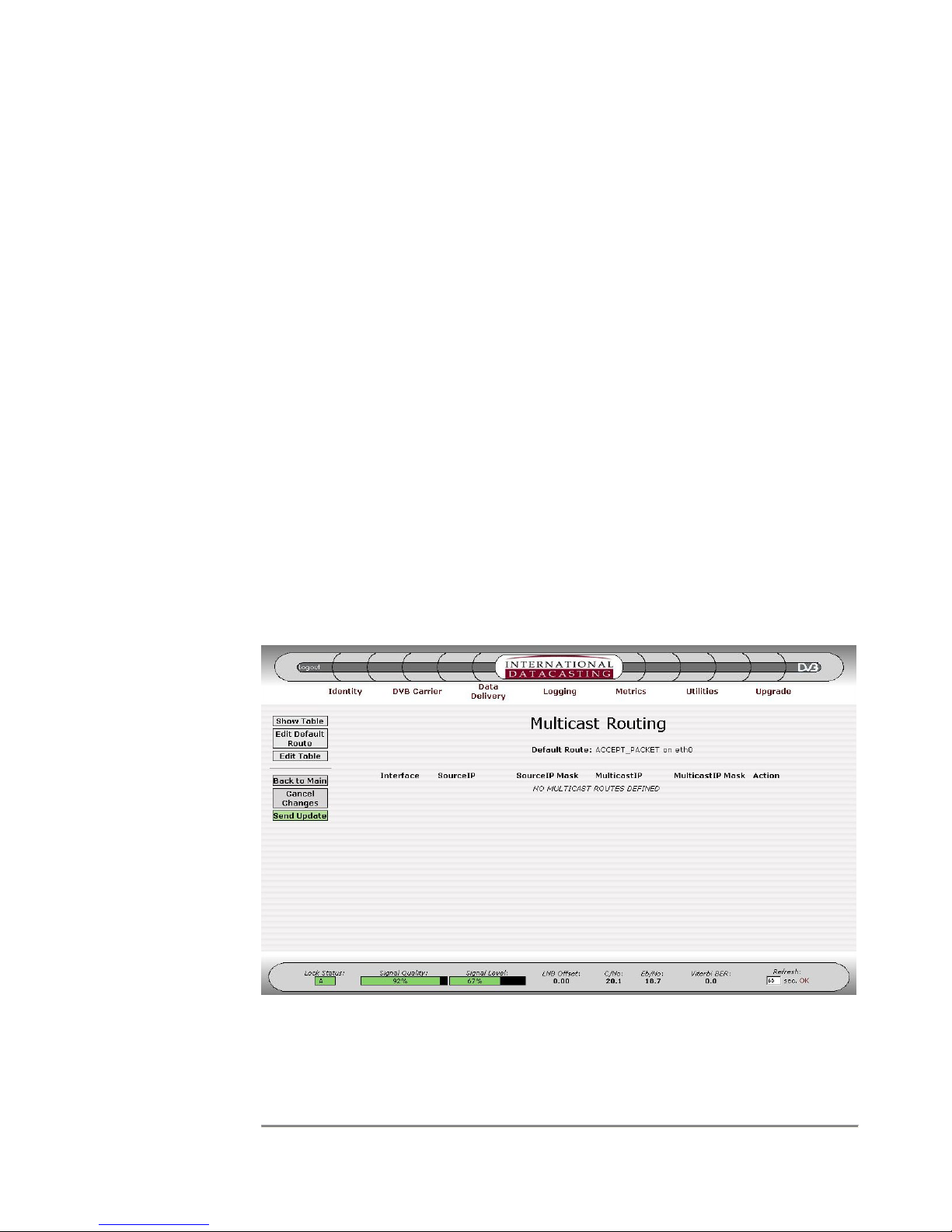
SRA/SFX2100 SERIES SATELLITE RECEIVER
that listens to 224.1.1.1:1234 is started on the receiver (e.g. XD). A static route for
this application is entered, to bind to the receiving socket:
Interface: eth0
Gateway: 0.0.0.0
Destination: 224.1.1.1
Netmask: 255.255.255.255
From the previous Local Application Rule #2, we know that output of 224.1.1.1 on
eth0 will stop. Output of 224.1.1.1 on eth1 will, however, continue. Only if the
incoming multicast IP packets are fragmented, the application may see
occasional packet loss. The loss will not be constant or periodic and no packets
will be lost on the eth1 output. The rule in this case is to bind the static route to an
interface that is not being used to output the multicast traffic (via a multicast route).
So in the above example, you must change the static route to:
Interface: sat0
Gateway: 0.0.0.0
Destination: 224.1.1.1
Netmask: 255.255.255.255
When the Multicast Routing submenu item is selected under Data Delivery, the Multicast
Routing page is displayed for all network interfaces. A sample Multicast Routing page is
shown in Figure 4-20.
The columns in the Multicast Routing page are described under the Edit Default Route
page (Figure 4-21) and Edit Multicast Routing Table page (Figure 4-22).
Figure 4-20 Multicast Routing Page
67

SRA/SFX2100 SERIES SATELLITE RECEIVER
Aside from the Common Menu Items, the following menu items are available:
Menu Item Description
Show Table Selecting this button will always return you back to the Multicast
Routing page, as shown in Figure 4-20.
Edit Default
Route
Selecting this button will enter the Edit Default Route page, as
shown in Figure 4-21.
Edit Table Selecting this button will enter the Edit Multicast Routing Table
page, as shown in Figure 4-22.
Figure 4-21 Edit Default Route Page
The following fields can be edited on the Edit Default Route page:
Edit Field Description
Interface This drop down box selects the network interface that will be the
destination of the routed multicast IP packets. This selection
allows you to specify exactly where the multicast packets should
be output, given the Action below specifying how they should be
output. The following selections are available:
NET1 (eth0) – output only on NET1 port.
NET2 (eth1) – output only on NET2 port.
NET1&2 (eth0&1) – output on both NET1 and NET2.
ALL – output on all network interfaces.
Action This drop down box selects the default action that will be taken
68

NOTE
:
There
are limitations
to the selection
combinations
of Interface and
Action: “ALL”
cannot be used
with “ACCEPT
PACKET”, but
must be used
for “DISCARD
PACKET” and
“PASS TO
IGMP”. If
“PASS TO
IGMP” is used,
make sure
IGMP is
enabled on the
appropriate
network
interface(s).
SRA/SFX2100 SERIES SATELLITE RECEIVER
Edit Field Description
on the multicast packet being routed. The following selections
are available:
ACCEPT_PACKET – accept packet and output according to
Interface above.
DISCARD_PACKET – throw away the packet.
PASS_TO_IGMP – pass the packet on to for processing by the
IGMP function, before being output on the Interface above.
NOTE: The
SourceIP fields
are optional,
and “Any” is
the implied
default value.
Figure 4-22 Edit Multicast Routing Table Page
The following fields can be edited on the Edit Multicast Routing Table page:
Edit Field Description
Interfaces This drop down box selects the network interface that will be the
destination of the routed multicast IP packets. This selection
allows you to specify exactly where the multicast packets should
be output. The selections available are the same as the
Interface in the Edit Default Route.
! Clicking on the “not” (!) check box negates the logic for the
immediate edit field to the right of the check box. For example, !
224.1.1.1 for the Source IP would mean all IP addresses whose
source IP address is not 224.1.1.1.
SourceIP Enter a source IP Address in dotted decimal notation, here if you
wish. “Any” is implied if no Source IP is entered.
69

SRA/SFX2100 SERIES SATELLITE RECEIVER
Edit Field Description
SourceIP Mask Enter a netmask for the source IP address. This field is optional
and 255.255.255.255 is implied if no SourceIP mask is entered.
MulticastIP Enter a multicast destination IP Address in dotted decimal
notation. You must enter a valid multicast address in this field.
NOTE: The
same
limitations
apply for
Interfaces and
Action as in the
previous note.
MulticastIP Mask Enter a netmask for the multicast IP address. This field is
optional and 255.255.255.255 is the default if you do not enter a
mask.
Action Select an action to be taken on the multicast IP packet being
routed. The selections available are the same as the Action in
the Edit Default Rule.
In addition to the edit fields there are four table row manipulation keys:
Key Description
Add Add the entered information above the table to the table as the
last row.
Remove Delete the selected (highlighted) row.
Up If there is more than one row in the table, move the selected row
up one row.
Down If there is more than one row in the table, move the selected row
down one row.
70

SRA/SFX2100 SERIES SATELLITE RECEIVER
Source NAT
The Source Network Address Translation (SNAT) submenu is responsible for maintenance
of source IP address translation, which forms part of the IP packet Filtering Function in the
receiver. This table defines up to 25 rules that can be used to filter on various IP packet
headers and perform a source address translation or masquerading function. The rules in
the Source NAT Table are applied to IP packets, typically independent of the network
interface they originated from.
Source NAT is done using options within the Linux iptables facility. More information on
iptables can be obtained from the manual or tutorial online at sites such as
http://www.redhat.com
the iptables tutorial (see Chapter 5). The iptables facility under Linux is extensive and
complex; and Source NAT is only one part of this facility. The Source NAT submenu is
intended to make configuration of this function more user friendly.
Source NAT of incoming IP packets is performed by the receiver according to the following
rules:
1. IP packets can originate from any of the available network interfaces and are
processed by the receiver in accordance with the data flow in Figure 4-9.
. Additionally, you can contact IDC Customer Service for a copy of
2. Up to 25 rules can be maintained by the Source NAT table. Rules are executed
from the first rule to the last rule, in sequence. Order matters; the first rule that is
applicable to the incoming packet is applied. Subsequent rules after that are
ignored.
3. If there is no applicable rule in the Source NAT table, the default rule is applied to
the incoming packet.
4. Packets can be filtered by Source IP Address/Port or Destination IP Address/Port,
or both. Ports can only be specified if UDP or TCP protocols are selected.
5. Two types of actions can be taken on the incoming packet where a rule applies:
a) Source Network Address Translation (SNAT) – the source IP address/port on
the incoming packet is replaced with a new source address/port, as specified
in the rule; or
b) Masquerading (MASQ) – the source IP address on the incoming packet is
replaced with the IP address of the network interface of the receiver, which will
be used to output the packet onto the LAN (e.g. NET1/eth0 IP address if the
packet is going out the NET1/eth0 interface).
6. Provision is made in the rule table for additional iptables options, allowing for
maximum flexibility. However, extreme care should be taken when using additional
options, and the iptables manual must be consulted in this case. (One example of
an option usage could be to specify a source network interface for the incoming
packets.)
71

SRA/SFX2100 SERIES SATELLITE RECEIVER
When the Source NAT submenu item is selected under Data Delivery, the Source NAT
Table page is displayed for all applicable source address translation rules. A sample
Source NAT Table page is shown in Figure 4-23.
Figure 4-23 Source NAT Table Page
The columns in the Source NAT Table page are described under the Edit Source NAT
Default Rule page (Figure 4-24) and Edit Source NAT Table page (Figure 4-25).
Aside from the Common Menu Items, the following menu items are available:
Menu Item Description
Show SNAT
Table
Selecting this button will always return you back to the Source
NAT Table page, as shown in Figure 4-23.
Edit Default Rule Selecting this button will enter the Edit Source NAT Default Rule
page, as shown in Figure 4-24.
Edit SNAT Table Selecting this button will enter the Edit Source NAT Table page,
as shown in Figure 4-25.
72

SRA/SFX2100 SERIES SATELLITE RECEIVER
NOTE: The
Default Rule
should always
be set to
ACCEPT.
DROP should
only be used
under certain
circumstances
and may cause
all packets not
to be forwarded
for further
processing.
Figure 4-24 Edit Source NAT Default Rule Page
The following fields can be edited on the Edit Source NAT Default Rule page:
Edit Field Description
Rule Status This drop down box selects the default action that will be taken
on an incoming IP packet if there was no rule match in the
SNAT Table. The following selections are available:
ACCEPT – accept packet and continue processing and output.
DROP – throw away the packet.
73
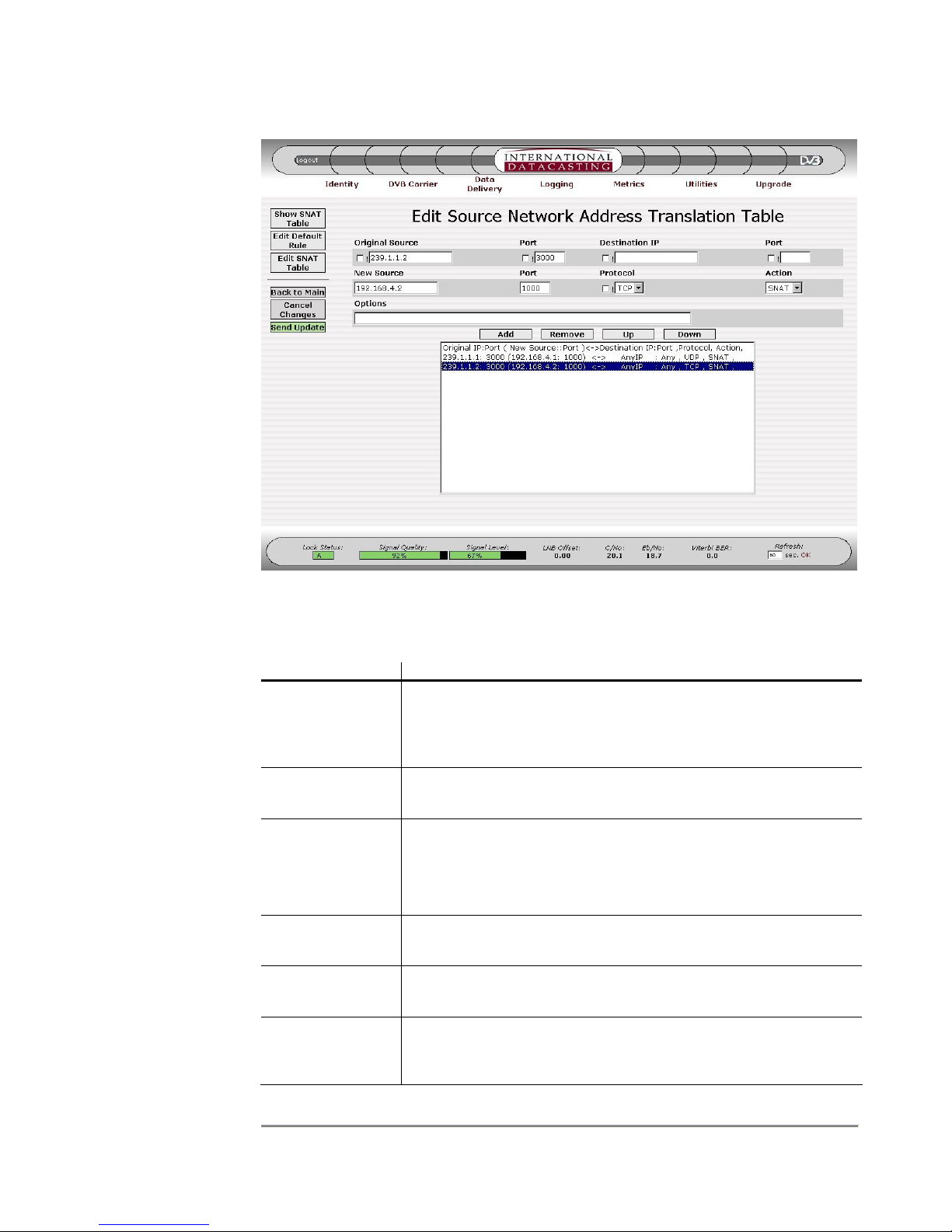
SRA/SFX2100 SERIES SATELLITE RECEIVER
NOTE: The
Original Source
IP/Port and
Destination
IP/Port fields
are optional,
and “Any” is
the implied
default value.
Figure 4-25 Edit Source NAT Table Page
The following fields can be edited on the Edit SNAT Table page:
Edit Field Description
! Clicking on the “not” (!) check box negates the logic for the
immediate edit field to the right of the check box. For example,
!224.1.1.1 for the Source IP would mean all IP packets whose
source IP address is not 224.1.1.1.
Original Source Enter a source IP Address in dotted decimal notation, here if you
wish to filter IP packets on their original source address.
Port
(Original Source,
Destination IP, &
Enter a TCP or UDP Port number in any of the three port fields,
if you wish. If a port is specified, you must select a specific
protocol (TCP or UDP).
New Source)
Destination IP Enter a Destination IP Address in dotted decimal notation, here
if you wish to filter IP packets on their destination IP address.
New Source Enter a New Source IP address that will replace the Original
Source IP address, if using SNAT as the action.
Protocol Enter the IP packet protocol. Options are Any Protocol (default),
UDP/IP Protocol, or TCP/IP Protocol. If port numbers are
specified in a rule, you must select UDP or TCP.
74

NOTE: New
SNAT rules
committed to the
table (when
Send Update is
pressed) may not
take immediate
effect if the
applicable IP
data stream is in
progress. A
suitable period of
no data activity
for that IP stream
(as determined
by Linux) may
need to take
place first before
the new rule
applies.
SRA/SFX2100 SERIES SATELLITE RECEIVER
Edit Field Description
Action Select an action to be taken for source address translation. The
two selections are:
SNAT – replace Original Source IP/port with New Source IP/Port
and continue processing the packet.
MASQ – Masquerade – replace Original Source IP with the IP
address of the network interface where the IP packet is output.
NOTE: A new Port number is selected by the receiver.
Options This field is available for “power users”, who wish to enter
additional iptables options. Care must be taken in doing so, and
order may matter on entry of options. Some combinations may
not be possible. Consult the Linux iptables manual or tutorial for
more information.
In addition to the edit fields there are four table row manipulation keys:
Key Description
Add Add the entered information above the table to the table as the
last row.
Remove Delete the selected (highlighted) row.
Up If there is more than one row in the table, move the selected row
up one row.
Down If there is more than one row in the table, move the selected row
down one row.
75

SRA/SFX2100 SERIES SATELLITE RECEIVER
Destination NAT
The Destination Network Address Translation (DNAT) submenu is responsible for
maintenance of destination IP address translation, which forms part of the IP packet
Filtering Function in the receiver. This table defines up to 25 rules that can be used to filter
on various IP packet headers and perform a destination address translation. The rules in
the Destination NAT Table are applied on incoming IP data, typically independent of the
network interface the packet originated from.
Destination NAT is done using options within the Linux iptables facility. More information
on iptables can be obtained from the manual or tutorial online at sites such as
http://www.redhat.com
the iptables tutorial (see Chapter 5). The iptables facility under Linux is extensive and
complex; and Destination NAT is only one part of this facility. The Destination NAT
submenu is intended to make configuration of this function more user friendly.
Destination NAT of incoming IP packets is performed by the receiver according to the
following rules:
1. IP packets can originate from any of the available network interfaces and are
processed by the receiver in accordance with the data flow in Figure 4-9.
. Additionally, you can contact IDC Customer Service for a copy of
2. Up to 25 rules can be maintained by the Destination NAT table. Rules are
executed from the first rule to the last rule, in sequence. Order matters; the first
rule that is applicable to the incoming packet is applied. Subsequent rules after
that are ignored.
3. If there is no applicable rule in the Destination NAT table, the default rule is applied
to the incoming packet.
4. Packets can be filtered by Source IP Address/Port or Destination IP Address/Port,
or both. Ports can only be specified if UDP or TCP protocols are selected.
5. Where a rule applies to a packet, Destination Network Address Translation (DNAT)
will be performed every time – the destination IP address/port on the incoming
packet is replaced with a new destination address/port, as specified in the rule.
6. Provision is made in the rule table for additional iptables options, allowing for
maximum flexibility. However, extreme care should be taken when using additional
options, and the iptables manual must be consulted in this case. (One example of
an option usage could be to specify a source network interface for the incoming
packets.)
When the Destination NAT submenu item is selected under Data Delivery, the Destination
NAT Table page is displayed for all applicable destination address translation rules. A
sample Destination NAT Table page is shown in Figure 4-26. (One example of an option
usage could be to specify a source network interface for the incoming packets.)
76
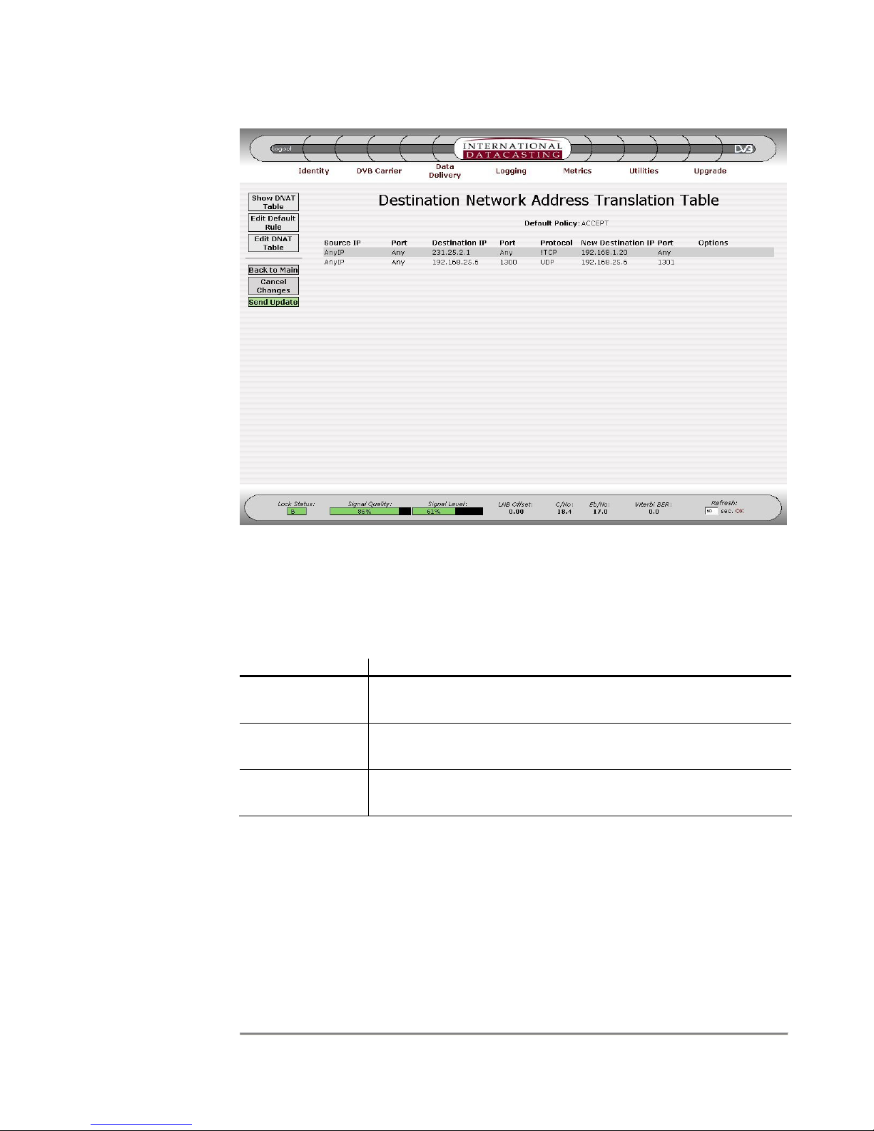
SRA/SFX2100 SERIES SATELLITE RECEIVER
Figure 4-26 Destination NAT Table Page
The columns in the Destination NAT Table page are described under the Edit Destination
NAT Default Rule page (Figure 4-27) and Edit Destination NAT Table page (Figure 4-28).
Aside from the Common Menu Items, the following menu items are available:
Menu Item Description
Show DNAT
Table
Selecting this button will always return you back to the
Destination NAT Table page, as shown in Figure 4-26.
Edit Default Rule Selecting this button will enter the Edit Destination NAT Default
Rule page, as shown in Figure 4-27.
Edit DNAT Table Selecting this button will enter the Edit Destination NAT Table
page, as shown in Figure 4-28.
77
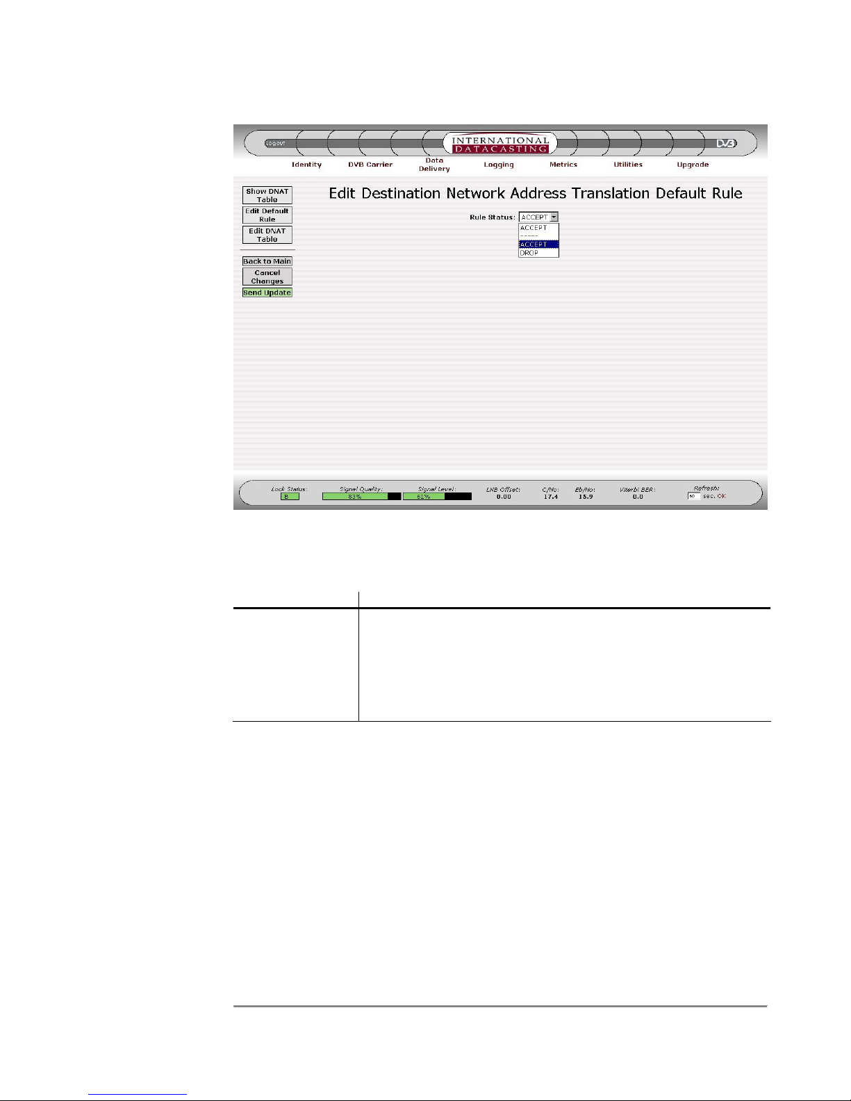
SRA/SFX2100 SERIES SATELLITE RECEIVER
NOTE: The
Default Rule
should always
be set to
ACCEPT.
DROP should
only be used
under certain
circumstances
and may cause
all packets not
to be forwarded
for further
processing.
Figure 4-27 Edit Destination NAT Default Rule Page
The following fields can be edited on the Edit Destination NAT Default Rule page:
Edit Field Description
Rule Status This drop down box selects the default action that will be taken
on an incoming IP packet if there was no rule match in the
DNAT Table. The following selections are available:
ACCEPT – accept packet and continue processing and output.
DROP – throw away the packet.
78
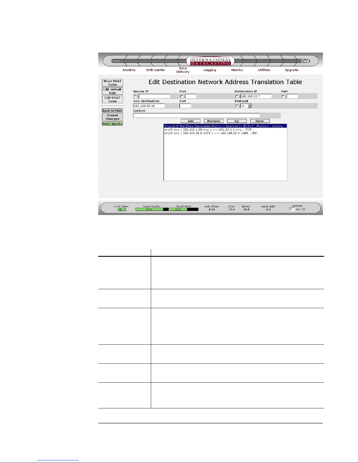
SRA/SFX2100 SERIES SATELLITE RECEIVER
NOTE: The
Source IP/Port
and Destination
IP/Port fields
are optional,
and “Any” is
the implied
default value.
Figure 4-28 Edit Destination NAT Table Page
The following fields can be edited on the Edit DNAT Table page:
Edit Field Description
! Clicking on the “not” (!) check box negates the logic for the
immediate edit field to the right of the check box. For example,
!224.1.1.1 for the Source IP would mean all IP packets whose
source IP address is not 224.1.1.1.
Source IP Enter a source IP Address in dotted decimal notation, here if you
wish to filter IP packets on their source address.
Port
(Source IP,
Destination IP, &
Enter a TCP or UDP Port number in any of the three port fields,
if you wish. If a port is specified, you must select a specific
protocol (TCP or UDP).
New Destination)
Destination IP Enter a Destination IP Address in dotted decimal notation, here
if you wish to filter IP packets on their destination IP address.
New Destination Enter a New Destination IP address that will replace the original
Destination IP address.
Protocol Enter the IP packet protocol. Options are Any Protocol (default),
UDP/IP Protocol, or TCP/IP Protocol. If port numbers are
specified in a rule, you must select UDP or TCP.
79

NOTE: New
DNAT rules
committed to the
table (when
Send Update is
pressed) may not
take immediate
effect if the
applicable IP
data stream is in
progress. A
suitable period of
no data activity
for that IP stream
(as determined
by Linux) may
need to take
place first before
the new rule
applies.
SRA/SFX2100 SERIES SATELLITE RECEIVER
Edit Field Description
Options This field is available for “power users”, who wish to enter
additional iptables options. Care must be taken in doing so, and
order may matter on entry of options. Some combinations may
not be possible. Consult the Linux iptables manual or tutorial for
more information.
In addition to the edit fields there are four table row manipulation keys:
Key Description
Add Add the entered information above the table to the table as the
last row.
Remove Delete the selected (highlighted) row.
Up If there is more than one row in the table, move the selected row
up one row.
Down If there is more than one row in the table, move the selected row
down one row.
80

SRA/SFX2100 SERIES SATELLITE RECEIVER
Filtering
The Filtering submenu is responsible for maintenance of the Filtering Table in the receiver.
This table defines up to 25 rules that can be used to filter on various IP packets, either by IP
header or MAC address criteria. Filtering is performed on incoming IP data, regardless of
the network interface the packet originated from.
Filtering is done using options within the Linux iptables facility. More information on
iptables can be obtained from the manual or tutorial online at sites such as
http://www.redhat.com
the iptables tutorial (see Chapter 5). The iptables facility under Linux is extensive and
complex; and Filtering is only one part of this facility. The Filtering submenu is intended to
make configuration of this function more user friendly.
Filtering of incoming IP packets is performed by the receiver according to the following
rules:
1. IP packets can originate from any of the available network interfaces and are
processed by the receiver in accordance with the data flow in Figure 4-9.
2. Up to 25 filtering rules can be maintained by the table. Rules are executed from
the first rule to the last rule, in sequence. Order matters; the first rule that is
applicable to the incoming packet is applied. Subsequent rules after that are
ignored.
. Additionally, you can contact IDC Customer Service for a copy of
3. If there is no applicable rule in the Filtering table, the default rule is applied to the
incoming packet.
4. Packets can be filtered by Source IP Address/Port or Destination IP Address/Port,
or both. Ports can only be specified if UDP or TCP protocols are selected.
5. Provision is made in the rule table for additional iptables options, allowing for
maximum flexibility. However, extreme care should be taken when using additional
options, and the iptables tutorial must be consulted in this case. (One example of
an option usage is for MAC Address Filtering, using options like: “–m mac –mac-
source xx:xx:xx:xx:xx:xx”.)
When the Filtering submenu item is selected under Data Delivery, the Filtering Table page
is displayed for all applicable filtering rules. A sample Filtering Table page is shown in
Figure 4-29.
81
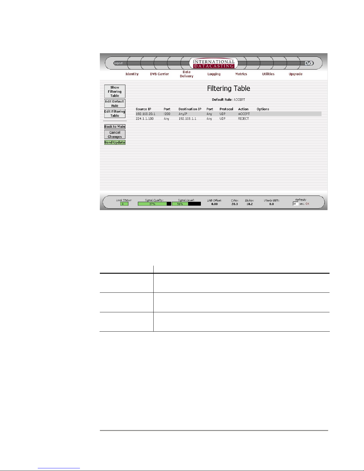
SRA/SFX2100 SERIES SATELLITE RECEIVER
Figure 4-29 Filtering Table Page
The columns in the Filtering Table page are described under the Edit Default Filtering Rule
page (Figure 4-30) and Edit Filtering Table page (Figure 4-31).
Aside from the Common Menu Items, the following menu items are available:
Menu Item Description
Show Filtering
Table
Selecting this button will always return you back to the Filtering
Table page, as shown in Figure 4-29.
Edit Default Rule Selecting this button will enter the Edit Default Filtering Rule
page, as shown in Figure 4-30.
Edit Filtering
Table
Selecting this button will enter the Edit Filtering Table page, as
shown in Figure 4-31.
82

SRA/SFX2100 SERIES SATELLITE RECEIVER
Figure 4-30 Edit Default Filtering Rule Page
The following fields can be edited on the Edit Default Filtering Rule page:
Edit Field Description
Rule Status This drop down box selects the default action that will be taken
on an incoming IP packet if there was no rule match in the
Filtering Table. The following selections are available:
ACCEPT – accept packet and continue processing and output.
DROP – throw away the packet.
83

SRA/SFX2100 SERIES SATELLITE RECEIVER
NOTE: The
Source IP/Port
and Destination
IP/Port fields
are optional,
and “Any” is
the implied
default value.
Figure 4-31 Edit Filtering Table Page
The following fields can be edited on the Edit Filtering Table page:
Edit Field Description
! Clicking on the “not” (!) check box negates the logic for the
immediate edit field to the right of the check box. For example,
!224.1.1.1 for the Source IP would mean all IP packets whose
source IP address is not 224.1.1.1.
Source IP Enter a source IP Address in dotted decimal notation, here if you
wish to filter IP packets on their source IP address.
Port
(Source IP,
Destination IP)
Enter a TCP or UDP Port number in any of the two port fields, if
you wish. If a port is specified, you must select a specific
protocol (TCP or UDP).
Destination IP Enter a Destination IP Address in dotted decimal notation, here
if you wish to filter IP packets on their destination IP address.
Protocol Enter the IP packet protocol. Options are Any Protocol (default),
UDP/IP Protocol, or TCP/IP Protocol. If port numbers are
specified in a rule, you must select UDP or TCP.
Action Select an action to be taken for the filtering operation. The three
selections are:
84

SRA/SFX2100 SERIES SATELLITE RECEIVER
Edit Field Description
ACCEPT – accept packet and continue processing and output.
REJECT – throw away the packet, but send an ICMP
Destination Unreachable message back on the originating host
network interface. This is useful for eth0 and eth1 originating
packets. If the packets originated on the sat0 interface, the
ICMP message will be thrown away.
DROP – throw away the packet.
Options This field is available for “power users”, who wish to enter
additional iptables options. Care must be taken in doing so, and
order may matter on entry of options. Some combinations may
not be possible. Consult the Linux iptables manual or tutorial for
more information.
In addition to the edit fields there are four table row manipulation keys:
Key Description
Add Add the entered information above the table to the table as the
last row.
Remove Delete the selected (highlighted) row.
Up If there is more than one row in the table, move the selected row
up one row.
Down If there is more than one row in the table, move the selected row
down one row.
85

SRA/SFX2100 SERIES SATELLITE RECEIVER
Firewall
The Firewall submenu is responsible for maintenance of the Firewall Tables in the receiver
and is really a more advanced filtering mechanism. There are two tables: one for the input
chain and one for the output chain, and up to 25 rules can be used to filter on various IP
packets, either by IP header or MAC address criteria in each table. Firewall tables are used
to filter on incoming IP data, regardless of the network interface the packet originated from.
Firewalling is done using options within the Linux iptables facility. More information on
iptables can be obtained from the manual or tutorial online at sites such as
http://www.redhat.com
the iptables tutorial (see Chapter 5). The iptables facility under Linux is extensive and
complex; and Firewalling is only one part of this facility. The Firewall submenu is intended
to make configuration of this function more user friendly.
Firewalling is performed by the receiver according to the following rules:
1. IP packets can originate from any of the available network interfaces and are
processed by the receiver in accordance with the data flow in Figure 4-9.
2. Up to 50 filtering rules can be entered in the editable table – 25 for INPUT and 25
for OUTPUT. Rules are executed from the first rule to the last rule, in sequence.
Order matters; the first rule that is applicable to the incoming packet is applied.
Subsequent rules after that are ignored.
. Additionally, you can contact IDC Customer Service for a copy of
3. If there is no applicable rule in the appropriate Firewall table, the corresponding
Input or Output default rule is applied to the packet.
4. Packets can be filtered by Source IP Address/Port or Destination IP Address/Port,
or both. Ports can only be specified if UDP or TCP protocols are selected.
5. Provision is made in the rule table for additional iptables options, allowing for
maximum flexibility. However, extreme care should be taken when using additional
options, and the iptables manual must be consulted in this case. (One example of
an option usage is for MAC Address Filtering, using options like: “–m mac –mac-
source xx:xx:xx:xx:xx:xx”.)
When the Firewalling submenu item is selected under Data Delivery, the Firewall Table
page is displayed for all applicable firewalling rules. A sample Firewall Table page is shown
in Figure 4-32.
86

SRA/SFX2100 SERIES SATELLITE RECEIVER
Figure 4-32 Firewall Table Page
The columns in the Firewall Table page are described under the Edit Default Firewall Rule
page (Figure 4-33) and Edit Firewall Table page (Figure 4-34). There are two independent
tables displayed: one for the Input Chain and one for Output Chain. In the example in
Figure 4-32, some rules have been defined for the Input Chain, but none for the Output
Chain.
Aside from the Common Menu Items, the following menu items are available:
Menu Item Description
Show Firewall
Table
Selecting this button will always return you back to the Firewall
Table page, as shown in Figure 4-32.
Edit Default Rule Selecting this button will enter the Edit Default Firewall Rule
page, as shown in Figure 4-33.
Edit Firewall
Table
Selecting this button will enter the Edit Firewall Table page, as
shown in Figure 4-34.
87

SRA/SFX2100 SERIES SATELLITE RECEIVER
Figure 4-33 Edit Default Firewall Rule Page
The following fields can be edited on the Edit Default Firewall Rule page:
Edit Field Description
Input Chain
Rule Status
This drop down box selects the default action that will be taken
on an IP packet processed at the Input Chain, if there was no
rule match in the Firewall Table (INPUT rules). The following
selections are available:
ACCEPT – accept packet and continue processing.
DROP – throw away the packet.
Output Chain
Rule Status
This drop down box selects the default action that will be taken
on an IP packet processed at the Output Chain, if there was no
rule match in the Firewall Table (OUTPUT rules). The following
selections are available:
ACCEPT – accept packet and continue processing and output.
DROP – throw away the packet.
88

SRA/SFX2100 SERIES SATELLITE RECEIVER
NOTE: The
Source IP/Port
and Destination
IP/Port fields
are optional,
and “Any” is
the implied
default value.
Figure 4-34 Edit Firewall Table Page
The following fields can be edited on the Edit Filtering Table page:
Edit Field Description
! Clicking on the “not” (!) check box negates the logic for the
immediate edit field to the right of the check box. For example,
!224.1.1.1 for the Source IP would mean all IP packets whose
source IP address is not 224.1.1.1.
Source IP Enter a source IP Address in dotted decimal notation, here if you
wish to filter IP packets on their source IP address.
Port
(Source IP,
Destination IP)
Enter a TCP or UDP Port number in any of the two port fields, if
you wish. If a port is specified, you must select a specific
protocol (TCP or UDP).
Destination IP Enter a Destination IP Address in dotted decimal notation, here
if you wish to filter IP packets on their destination IP address.
Chain Select the Input or Output Chain. You can have 25 rules for the
input chain and 25 rules for the output chain.
Protocol Enter the IP packet protocol. Options are Any Protocol (default),
UDP/IP Protocol, or TCP/IP Protocol. If port numbers are
specified in a rule, you must select UDP or TCP.
89

SRA/SFX2100 SERIES SATELLITE RECEIVER
Edit Field Description
Action Select an action to be taken for the firewall operation. The three
selections are:
ACCEPT – accept packet and continue processing and output.
REJECT – throw away the packet, but send an ICMP
Destination Unreachable message back on the originating host
network interface. This is useful for eth0 and eth1 originating
packets. If the packets originated on the sat0 interface, the
ICMP message will be thrown away.
DROP – throw away the packet.
Options This field is available for “power users”, who wish to enter
additional iptables options. Care must be taken in doing so, and
order may matter on entry of options. Some combinations may
not be possible. Consult the Linux iptables manual or tutorial for
more information.
In addition to the edit fields there are four table row manipulation keys:
Key Description
Add Add the entered information above the table to the table as the
last row.
Remove Delete the selected (highlighted) row.
Up If there is more than one row in the table, move the selected row
up one row.
Down If there is more than one row in the table, move the selected row
down one row.
90

SRA/SFX2100 SERIES SATELLITE RECEIVER
TTL Translation
The Time-To-Live (TTL) Translation submenu is responsible for maintenance of the TTL
Translation Table. This table defines up to 25 rules that can be used to modify the value of
the TTL parameter in the header of an IP packet being processed by the receiver,
regardless of the network interface the packet originated from.
TTL Translation to incoming IP packets is performed by the receiver according to the
following rules:
1. Up to 25 rules can be maintained by the table. Rules are executed from the first
rule to the last rule, in sequence. All rules are executed for every packet.
2. IP packets can originate from any of the available network interfaces and are
processed by the receiver in accordance with the data flow in Figure 4-9.
3. The TTL value of an incoming packet can never be less than 1.
4. The TTL value of an outgoing packet must be greater than 0.
5. The TTL Translation Table rules are applied before the incoming packet is further
processed by the IP Stack (routing and so on). Multiple rules in the table can
applied to the same incoming packet, if they are applicable, and the effect will be
cumulative.
6. The operating system always decrements the TTL value of the incoming packet by
1, after the TTL Translation Table rules have been applied.
7. If an incoming packet has a TTL of 1 when it arrives, and no TTL Translation rules
cause the TTL value to change, it will be decremented to 0. Therefore, it will not be
output on any network device, however, it is still available if an internal application
requires it. If not, the packet is discarded.
8. The legal range of TTL values is 1 to 255. Any TTL SET, INC (increment), or DEC
(decrement) operation will be clamped at 1 or 255, if the operation causes a TTL
value to occur outside the legal range.
When the TTL Translation submenu item is selected under Data Delivery, the TTL
Translation Table page is displayed for all applicable TTL Translation rules. A sample TTL
Translation Table page is shown in Figure 4-35.
91
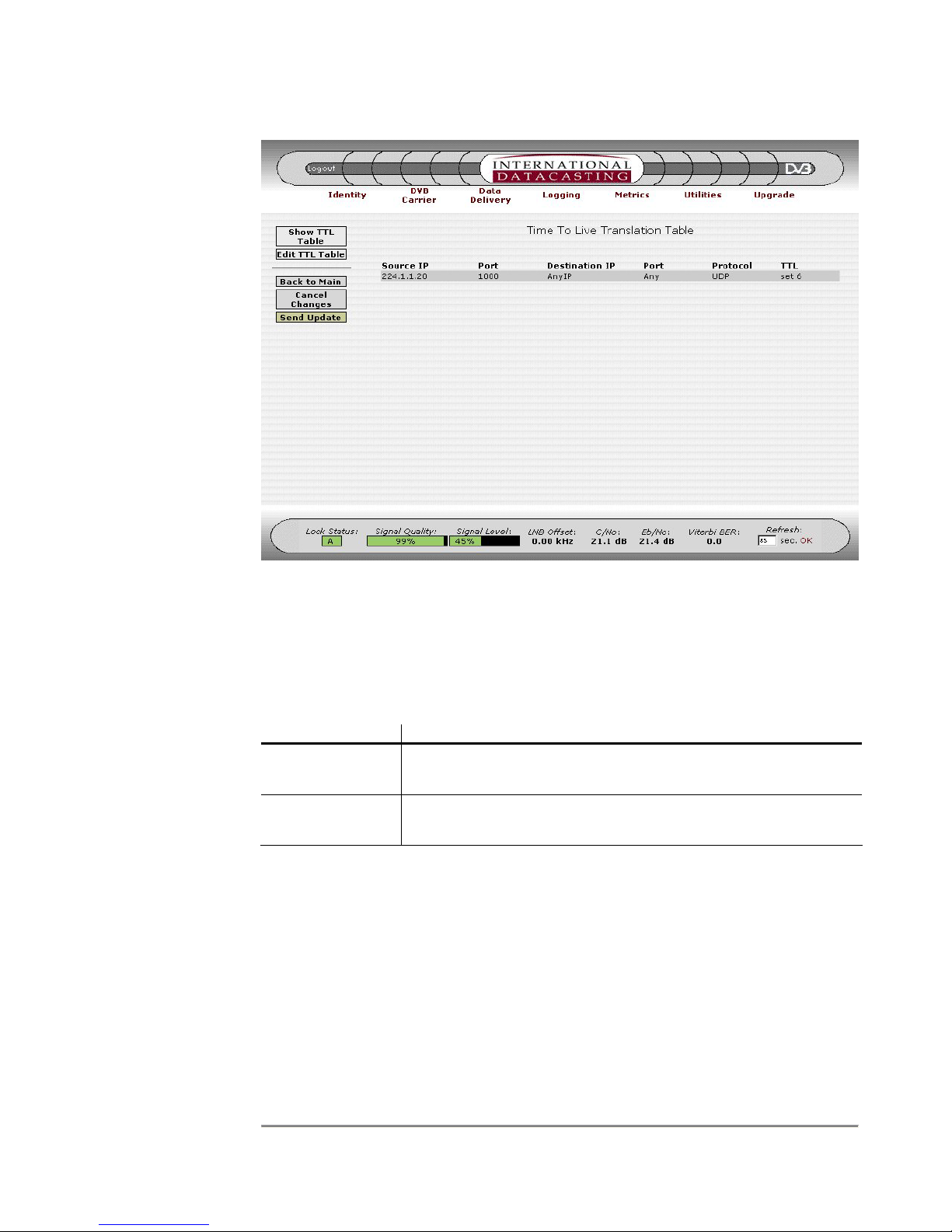
SRA/SFX2100 SERIES SATELLITE RECEIVER
Figure 4-35 TTL Translation Table Page
The columns in the table are described under the Edit TTL Translation Table page.
Aside from the Common Menu Items, the following menu items are available:
Menu Item Description
Show TTL Table Selecting this button will always return you back to the TTL
Translation Table page, as shown in the example in Figure 4-35.
Edit TTL Table Selecting this button will enter the Edit TTL Translation Table
page, as shown in the example in Figure 4-36.
92

SRA/SFX2100 SERIES SATELLITE RECEIVER
NOTE: If an
IP Address or
Port number
field is left
blank, “Any” is
the implied
default value.
Figure 4-36 Edit TTL Translation Table Page
The following fields can be edited on the Edit TTL Translation Table page:
Edit Field Description
! Clicking on the “not” (!) check box negates the logic for the
immediate edit field to the right of the check box. For example, !
224.1.1.1 for the Source IP would mean all IP packets whose
source IP address is not 224.1.1.1.
Source IP Enter a source IP Address in dotted decimal notation, here if you
wish to select IP packets on their source IP address.
(Source) Port Enter a source Port number here if you wish. If a port is
specified, you must select a specific protocol.
Destination IP Enter a destination IP Address in dotted decimal notation, here if
you wish to select IP packets on their destination IP address.
(Destination) Port Enter a destination Port number here if you wish. If a port is
specified, you must select a specific protocol.
Protocol Enter the IP packet protocol. Options are Any Protocol (default),
UDP/IP Protocol, or TCP/IP Protocol.
93

SRA/SFX2100 SERIES SATELLITE RECEIVER
Edit Field Description
Time To Live You must enter a TTL value operation in this field. Operations
can be SET, INC (increment) and DEC (decrement). TTL
values must be between 1 and 255. All TTL operations follow
the rules above.
In addition to the edit fields there are four table row manipulation keys:
Key Description
Add Add the entered information above the table to the table as the
last row.
Remove Delete the selected (highlighted) row.
Up If there is more than one row in the table, move the selected row
up one row.
Down If there is more than one row in the table, move the selected row
down one row.
94
 Loading...