

International comfort products PAT3 Series, WTA3 Series Installation Instructions Manual
Installation Instructions
WTA3 & PAT3 Series
PACKAGED AIR CONDITIONER
TABLE OF CONTENTS
Page
SAFE INSTALLATION REQUIREMENTS 2........
INTRODUCTION 2.............................
RECEIVING AND INSTALLATION 2...............
Check Equipment 2...........................
Provide Unit Support 2 -- 3.....................
Install Duct Connections 3.....................
Dimensions 4................................
Connect Condensate Drain 5..................
Install Electrical Connections 5 -- 10............
PRE--START--UP 11............................
START--UP 11..................................
Check for Refrigerant Leaks 11.................
Start--Up Cooling & Make Adjustments 11 -- 12..
Check and Adjust Charge 12 -- 14............
Airflow 15..................................
Sequence of Operation 15 -- 16..............
Page
MAINTENANCE 16.............................
Air Filter 16..................................
Unit Top Removal 16..........................
Indoor Blower and Motor 17....................
Outdoor & Indoor Coil, Condensate Drain Pan 17.
Outdoor Fan 17..............................
Electrical Controls and Wiring 18...............
Refrigeration Circuit 18........................
Evaporator Airflow 18.........................
Metering Devices 18..........................
Liquid Line Strainers 18.......................
High Flow Valves 18..........................
AIRFLOW CHARTS 19 -- 20.....................
COOLING TROUBLESHOOTING GUIDE 21.......
CHECKLIST FORM 22..........................
International Comfort Products, LLC
Lewisburg, TN. 37091
Printed in U.S.A.
426 01 1302 00 11--18--08
SAFE INSTALLATION REQUIREMENTS
FIGURE 1
Installation and servicing of this equipment can be
hazardous due to mechanical and electrical components.
Only trained and qualified personnel should install, repair,
or service this equipment.
Untrained personnel can perform basic maintenance
functions such as cleaning and replacing air filters. All other
operations must be performed by trained service
personnel. When working on this equipment, observe
precautions in the literature, on tags, andon labels attached
to or shipped with the unit and other safety precautions that
may apply.
Follow all safety codes. Installation must be in compliance
with local andnational building codes.Wear safety glasses,
protective clothing, and work gloves. Have fireextinguisher
available. Read these instructions thoroughly and follow all
warnings or cautions included in literature and attached to
the unit.
PACKAGED AIR CONDITIONER
!
CUT HAZARD
Failure to follow this caution may result in personal injury.
Sheet metal parts may have sharp edges or burrs. Use care
and wear appropriate protective clothing and gloves when
handling parts.
!
ELECTRICAL SHOCK HAZARD
Failure to follow this warning could result in personal
injury or death.
Before installing or servicing system, always turn off
main power to system. There may be more than one
disconnect switch. Turn off accessory heater power
switch if applicable. TAG DISCONNECT SWITCH
WITH LOCKOUT TAG.
Recognize safety information. This is the safety--alert
symbol . When you see this symbol in instructions or
manuals, be alert to the potential for personal injury.
Understand the signal words DANGER, WARNING,
CAUTION, and NOTE. These words are used with the
safety--alert symbol. DANGER identifies the most serious
hazards which will result in serious injury or death.
WARNING signifies a hazard which could result in serious
injury or death. CAUTION is used to identify unsafe
practices which may result in minor personal injury or
product and property damage. NOTE is used to highlight
suggestions which will result in enhanced installation,
reliability, or operation.
!
CAUTION
WARNING
INTRODUCTION
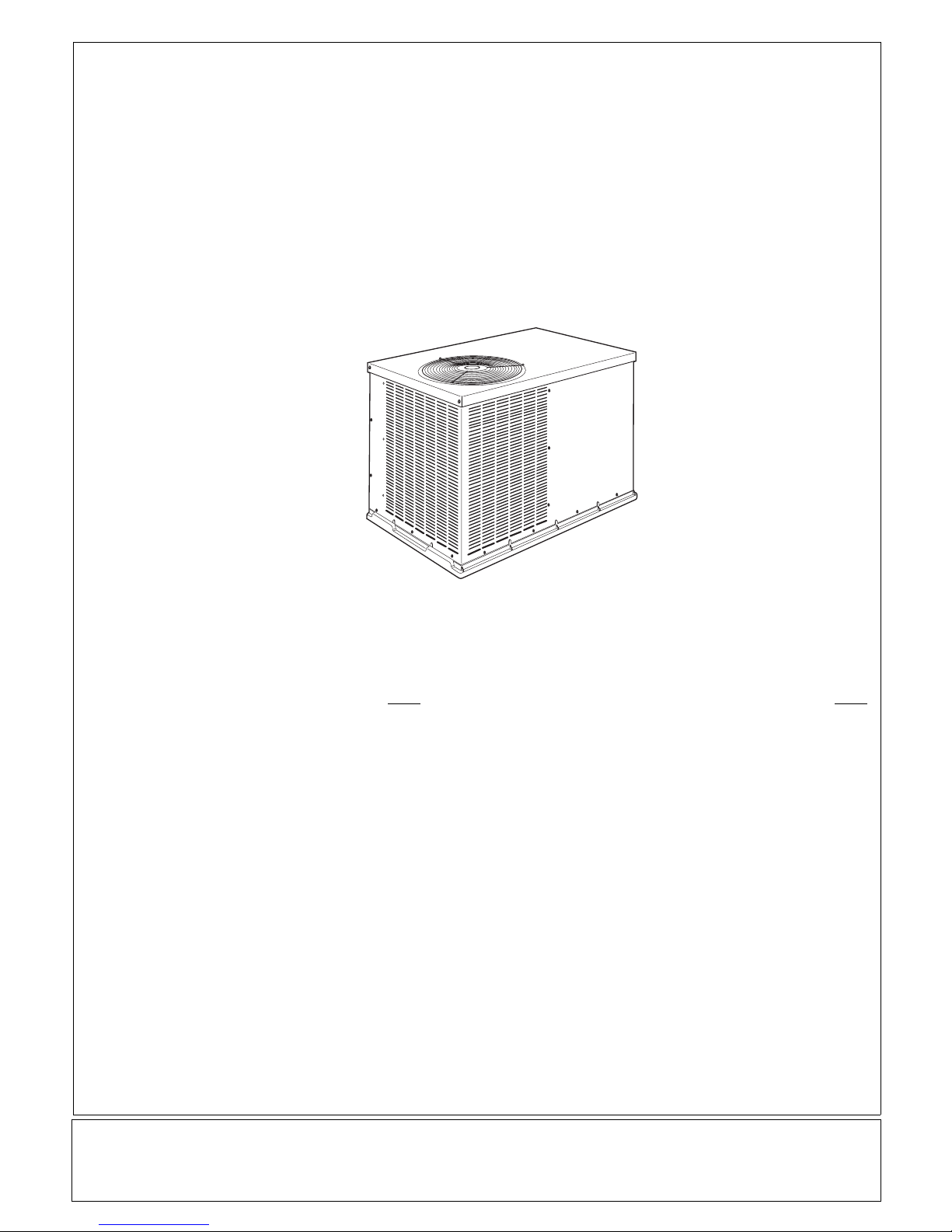
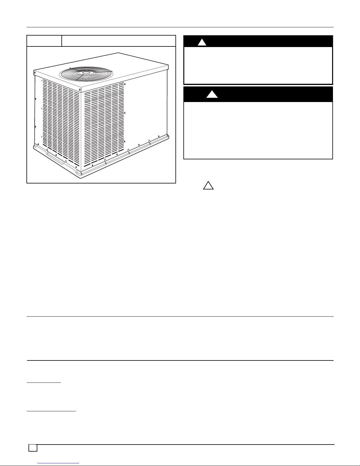
The packaged unit is a fully self--contained air conditioner
designed for outdoor installation (see Figure 3 for unit
dimensions). All unit sizes have return and discharge
openings for horizontal airflow.
RECEIVING AND INSTALLATION
STEP 1 — Check Equipment
Identify
The unit model number and serial number are stamped on
the unit information plate. Check this information against
shipping papers.
Inspect
Inspect for shipping damage while unit is still on shipping
pallet. If unit appears to be damaged or is torn loose from
its anchorage, have it examined by transportation
inspectors before removal.Forward claim papers directly to
2
Unit
Shipment
Units may be installed either on a rooftop, ground level
cement slab, or directly on the ground if local codes allow.
transportation company. Manufacturer is not responsible
for any damage incurred in transit. Check all items against
shipping list. Immediately notify the nearest equipment
distribution office if any item is missing. To prevent loss or
damage, leave all parts in original packages until
installation.
STEP 2 — Provide Unit Support
For hurricane tie downs, contact distributor for details and
PE (Professional Engineering) Certificate, if required.
Slab Mount
Place the unit on a solid, level concrete pad that is a
minimum of 4” (102mm) thick with 2” (51mm) above grade.
The slab should extend approximately 2” (51mm) beyond
the casing on all 4 sides of the unit. Do not secure the unit
to the slab except when required by local codes.
A 6” (152mm) wide gravel apronshould be used around the
flat surface to prevent airflow blockage by grass or shrubs.
The unit should be level within ¼”. This is necessary for the
unit drain to function properly.
Ground
Mount
The unit may be installed either on a slab or placed
directly on the ground, if local codes permit. Place the
unit on level ground prepared with gravel for condensate
discharge.
STEP 3 — Provide Clearances
The required minimum operating and service clearances
are shown in Figure 3. Adequate ventilation and condenser
air must be provided.
NOTE: Do not restrict outdoor airflow. An air restriction at
either the outdoor--air inlet or the fan discharge may be
detrimental to compressor life.
The condenser fan pulls air through the condenser coil and
discharges it through the top grille. Be sure that the fan
discharge does not recirculate to the condenser coil. Do not
locate the unit in either a corner or under an overhead
obstruction. The minimum clearance under a partial
overhang (such as a normal house overhang) is 48”
(1219mm). above the unit top. The maximum horizontal
extension of a partial overhang must not exceed 48”
(1219mm).
Do not place the unit where water, ice, or snow from an
overhang or roof will damage or flood the unit. Do not install
the unit on carpeting or other combustible materials.
Slab--mounted units should be at least 4” (102mm) above
the highest expected water and runoff levels. Do not use
unit if it has been under water.
Adhere to the following criteria when selecting, sizing, and
installing the duct system:
1. All units should have field--supplied filters installed in
the return--air side of the unit. Recommended sizes for
filters are shown in Table 1.
2. Avoid abrupt duct size increases and reductions.
Abrupt change in duct size adversely affects air
performance.
3. Size ductwork for cooling air quantity (CFM). The
minimum air quantity for proper electric heater
operation is listed in Table 10. Heater limit switches may
trip at air quantities below those recommended.
4. Seal, insulate, and weatherproof all external ductwork.
Seal, insulate and cover with a vapor barrier all
ductwork passing through conditioned spaces. Follow
latest Sheet Metal and Air Conditioning Contractors
National Association (SMACNA) and Air Conditioning
Contractors Association (ACCA) minimum installation
standards for residential heating and air conditioning
systems.
5. Secure all ducts to building structure. Flash,
weatherproof, and vibration--isolate duct openings in
wall or roof according to good construction practices.
6. Flash, weatherproof, and vibration isolate all openings
in building structure in accordance with local codesand
good building practices.
!
UNIT DAMAGE HAZARD
Failure to follow this caution may result in damage to unit
components.
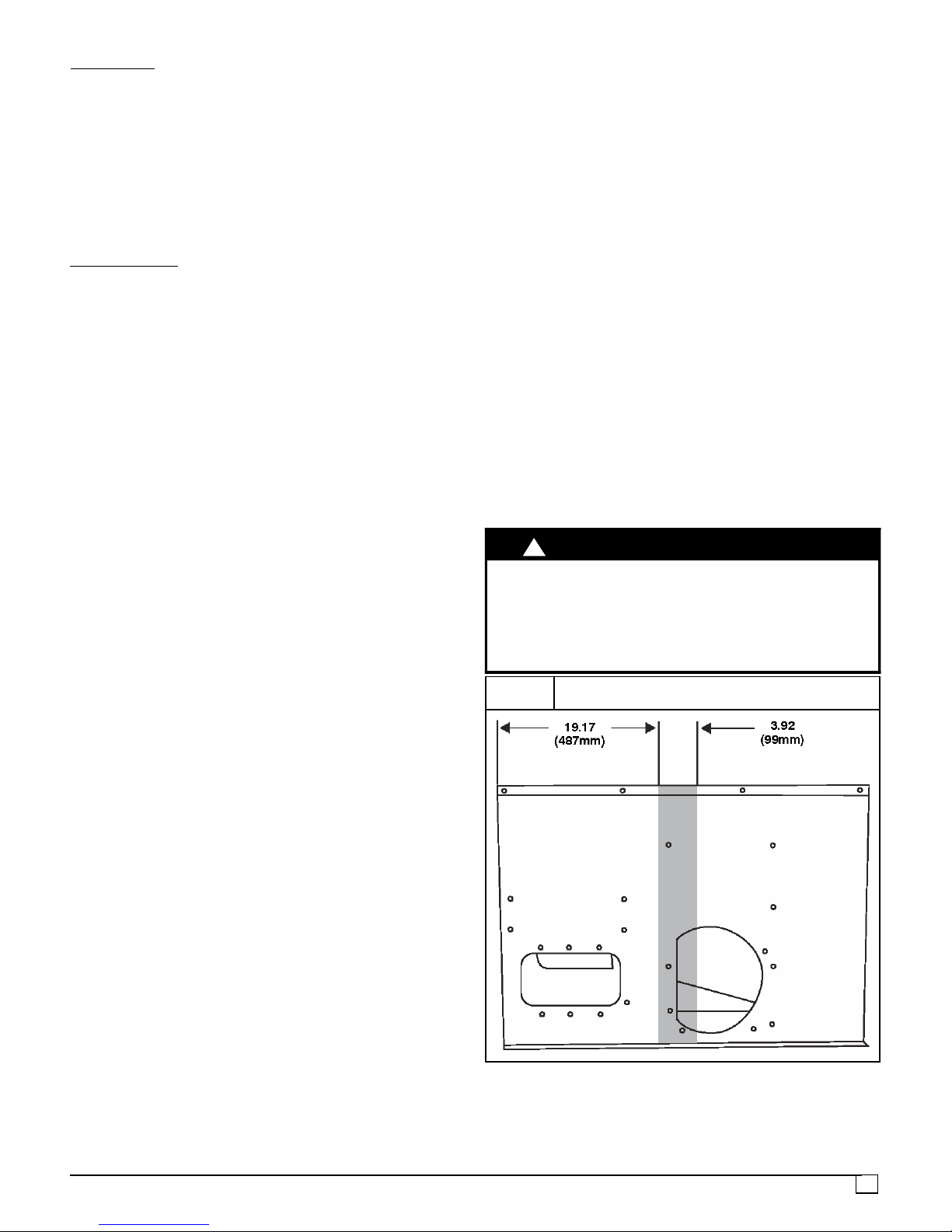
When connecting ductwork to unit, do not drill deeper than
¾” (19mm) in shaded area shown in Figure 2 or coil may be
damaged.
FIGURE 2
Do Not Drill Shaded Area Deeper Than ¾” (19mm)
CAUTION
STEP 4 — Install Duct Connections
The design and installation of the duct system must be in
accordance with the standards of the NFPA for
installation of non--residence type air conditioning and
ventilating systems, NFPA 90A or residence type, NFPA
90B and/or local codes and ordinances.
Select and size ductwork, supply air registers, and return
air grilles according to ASHRAE (American Society of
Heating, Refrigeration, and Air Conditioning Engineers)
recommendations.
Use the duct flanges provided on the supply and return
openings on theside of the unit. See Figure 3 for connection
sizes and locations. The 14” (356mm) round duct collars
are shipped inside the unit attached to the base pan in the
indoor blower compartment. They are for field installation
and must be removed from the indoor blower compartment
prior to start--up, even if they are not used for installation.
3
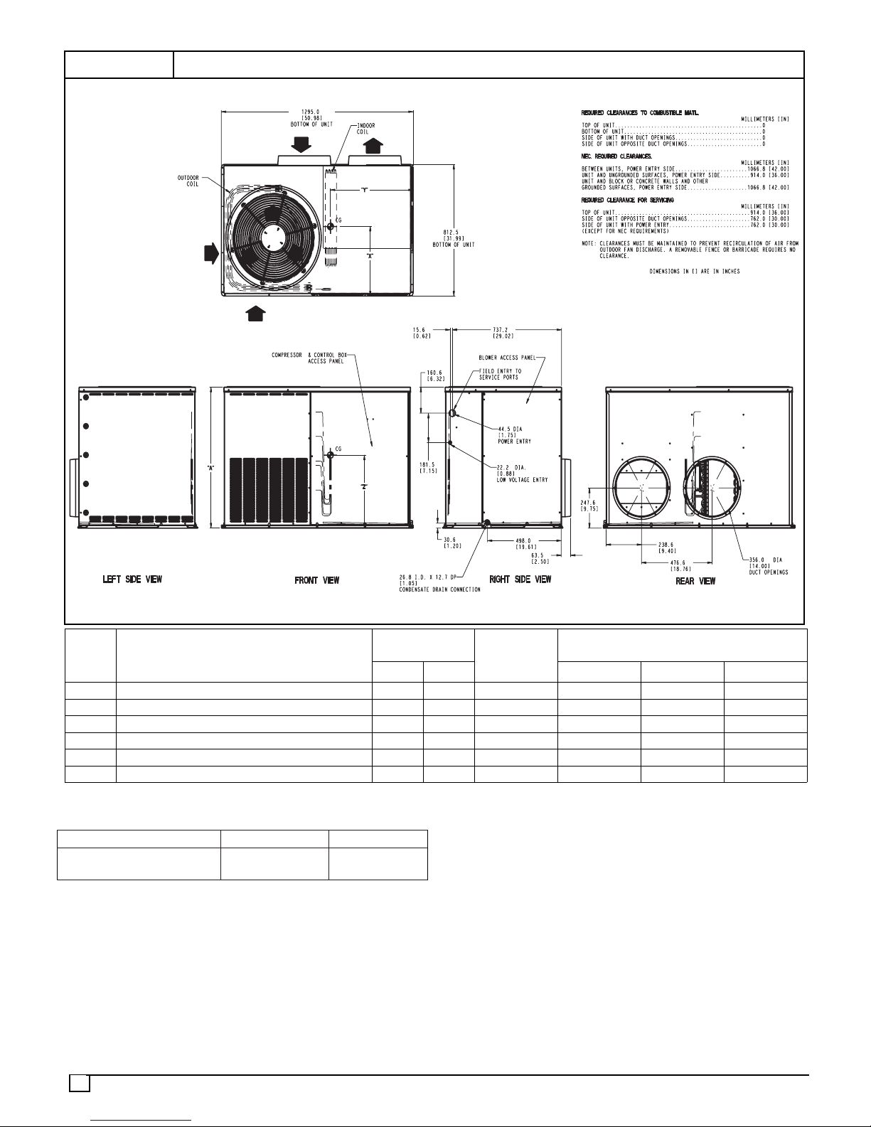
FIGURE 3
UNIT DIMENSIONS
Model
Size
24 208/230--1--60 268 121.6 30.13 [765] 14.0 [356] 19.0 [483] 15.0 [381]
30 208/230--1--60 299 135.6 34.13 [867] 14.0 [356] 19.0 [483] 16.0 [406]
36 208/230--1--60 352 159.7 42.13 [1070] 14.0 [356] 19.0 [483] 19.8 [503]
42 208/230--1--60 364 165.1 42.13 [1070] 14.0 [356] 19.0 [483] 21.9 [556]
48 208/230--1--60 359 162.8 42.13 [1070] 14.0 [356] 19.0 [483] 19.8 [503]
60 208/230--1--60 408 185.1 42.13 [1070] 14.0 [356] 19.0 [483] 21.9 [556]
ELECTRICAL
CHARACTERISTICS
UNIT WEIGHT
lbs kg X Y Z
UNIT
HEIGHT
in. [mm]
“A”
CENTER OF GRAVITY
inches [mm]
Table 1—Filter Data -- Throw--away Type
MODEL SIZE: 24, 30, 36 42, 48, 60
RETURN--AIR FILTER*
inches (mm)
24x24x1
(610x610x25)
30x30x1
(762x762x25)
* Required filter sizes shown are based on the larger of the
ARI (Air Conditioning and Refrigeration Institute) rated
cooling airflow or the heating airflow velocity of 300 feet per
minute for throwaway type or 450 feet per minute for
high--capacity type. Air filter pressure drop for
non--standard filters must not exceed 0.08 inches water
column.
4

STEP 5 — Connect Condensate Drain
NOTE: When installing condensate drain connection be
sure to comply with local codes and restrictions.
The packaged unit disposes of condensate water through
a w” NPT fitting which exits through the base on the
evaporator coil access side. See Figure 3 for location.
Condensate water can be drained directly onto the roof in
rooftop installations (where permitted) or onto a gravel
apron in ground level installations.Install a field--supplied 2”
(51mm) condensate trap at the end of condensate
connection to ensure proper drainage. Make sure that the
outlet of the trap is at least 1” (25mm) lower than the
drain--pan condensate connection to prevent the pan from
overflowing (see Figure 4). Prime the trap with water. When
using a gravel apron, make sure it slopes away from the
unit.
Connect a drain tube using a minimum of w” PVC or w”
copper pipe (all field--supplied) at the outlet end of the 2”
(51mm) trap. Do not undersize the tube. Pitch the draintube
downward at a slope of at least 1” (25mm). for every 10 feet
(3.0m) of horizontal run. Be sure to check the drain tube for
leaks.
FIGURE 4
Condensate Drain
!
UNIT COMPONENT DAMAGE HAZARD
Failure to follow this caution may result in damage to the
unit being installed.
1. Make all electrical connections in accordance with
NEC NFPA 70 (latest edition) and local electrical
codes governing such wiring. In Canada, all
electrical connections must be in accordance with
CSA standard C22.1 Canadian Electrical Code Part
1 and applicable local codes. Refer to unit wiring
diagram.
2. Use only copper conductor for connections between
field--supplied electrical disconnect switch and unit.
DO NOT USE ALUMINUM WIRE.
3. Be sure that high--voltage power to unit is within
operating voltage range indicated on unit rating
plate. Consult local power company for correction of
improper voltage and/or phase imbalance.
4. Insulate low--voltage wires for highest voltage
contained within conduit when low--voltage control
wires are in same conduit as high--voltage wires.
5. Do not damage internal components when drilling
through any panel to mount electrical hardware,
conduit, etc.
CAUTION
1” Min.
(25.4mm)
STEP 6 — Install Electrical Connections
!
ELECTRICAL SHOCK HAZARD
Failure to follow this warning could result in personal
injury or death.
The unit cabinet must have an uninterrupted, unbroken
electrical ground. This ground may consist of an
electrical wire connected to the unit ground screw in the
control compartment, or conduit approved for electrical
ground when installed in accordance with NEC, NFPA 70
National Fire Protection Association (latest edition) (in
Canada, Canadian Electrical Code CSA C22.1) and
local electrical codes.
WARNING
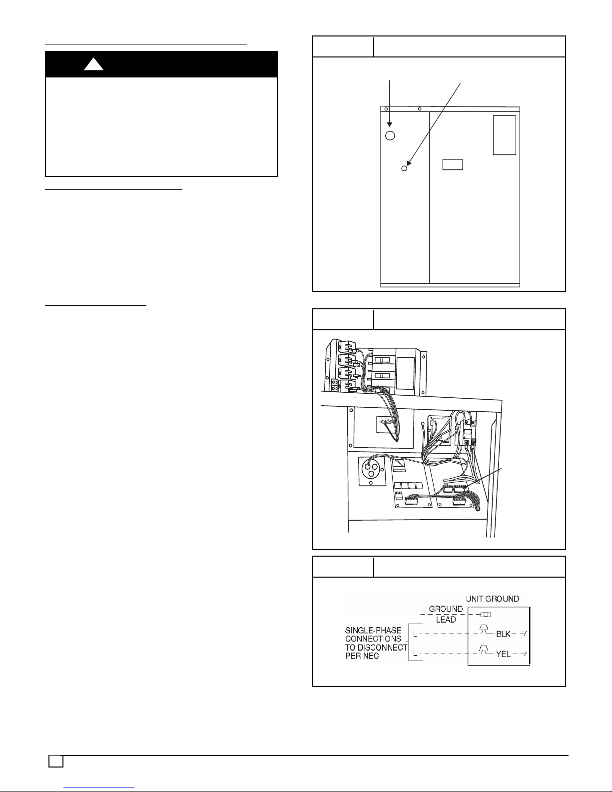
2” Min.
(51 mm)
High Voltage Connections
The unit must have a separate electrical service with a
field--supplied, waterproof disconnect switch mounted at, or
within sight from, the unit. Refer to the unit rating plate,NEC
and local codes for maximum fuse/circuit breaker size and
minimum circuit amps (ampacity) for wire sizing.
The field--supplied disconnect switch box may be mounted
on the unit over the high--voltage inlet hole when the
standard power and low--voltage entry points are used (see
Figure 3 and 5 for acceptable location).
When routing power leads into unit, use only copper wire
between disconnect and unit. The high voltage leads
should be in a conduit until they enter the duct panel;
conduit termination at the duct panel must be watertight.
See unit wiring label and Figures 10 -- 13 for reference when
making high voltage connections. Proceed as follows to
complete the high--voltage connections to the unit.
Single--phase units:
1. Run the high--voltage (L1, L2) and ground lead into the
control box.
2. Connect ground lead to chassis ground connection.
3. Locate the black and yellow wires connected to the line
side of the contactor.
4. Connect field L1 to black wire on connection 11 of the
compressor contactor.
5. Connect field wire L2 to yellow wire on connection 23 of
the compressor contactor.
5
Special Procedures For 208 Volt Operation
!
ELECTRICAL SHOCK HAZARD
Failure to follow this warning could result in personal
injury or death.
Before installing or servicing system, always turn off
main power to system. with disconnect switch open,
move black wire from transformer (x””) terminal marked
230 to terminal marked 208. This re--taps transformer to
primary voltage of 208 VAC.
WARNING
Control Voltage Connections
Do not use any type of power--stealing thermostat. Unit
control problems may result.
Use no. 18 American Wire Gage (AWG) color--coded,
insulated (35_C minimum) wires to make the control
voltage connections between the thermostat and the unit.
If the thermostat is located more than 100 feet from the unit
(as measured along the control voltage wires), use no. 16
AWG color--coded, insulated (35_C minimum) wires.
Standard
Connection
Form a drip--loop with the thermostat leads before routing
them into the unit. Route the thermostat leads through
grommeted hole provided in unit into unit control box (see
Figure 8). Connect thermostat leads and unit power leads
as shown in Figures 7, 8, and 9.
The unit transformer supplies 24 VAC power for the
complete system including accessory electrical heater.
Transformer is factory wired for 230 Volt operation.
Accessory Electric Heat W
iring
Refer to accessory electric heat installation instructions for
information on installingaccessory electric heat. Accessory
electric heat wiring is shown in Figure 12.
FIGURE 5
HIGH-VOLTAGE POWER
WIRING ENTRY HOLE
FIGURE 6
Electrical Entry Locations
LOW-VOLTAGE WIRING
ENTRY HOLE
Control Box Wiring
HEATER LOW
VOLTAGE PLUG
6
FIGURE 7
High Voltage (Line) Connections
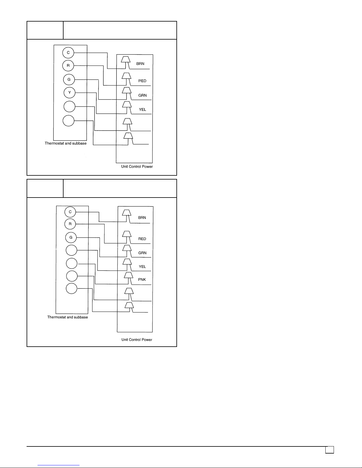
FIGURE 8
Low Voltage (Control) Connections,
Model Sizes 24, 30, 36, 42, 48
W2
FIGURE 9
W3
WHT
VIO
Low Voltage (Control) Connections,
Model Size 60
Y1
Y2
W2
W3
WHT
VIO
7
 Loading...