

International Comfort Products R2A318GKR100, R2A324GKR100, R2A330GKR100, R2A336GKR100, R2A342GKR100 User Manual
...
TECHNICAL SUPPORT MANUAL
Air Conditioner Component
R2A3**GKR
Safety Labeling and Signal Words
DANGER, WARNING, CAUTION, and
NOTE
The signal words DANGER, WARNING, CAUTION, and NOTE are used to identify levels of haz-
ard seriousness. The signal word DANGER is only
used on product labels to signify an immediate hazard. The signal words WARNING, CAUTION, and
NOTE will be used on product labels and throughout this manual and other manuals that may apply
to the product.
DANGER − Immediate hazards which will result in
severe personal injury or death.
WARNING − Hazards or unsafe practices which
could result in severe personal injury or death.
CAUTION − Hazards or unsafe practices which
may result in minor personal injury or product or
property damage.
NOTE − Used to highlight suggestions which will
result in enhanced installation, reliability, or operation.
Signal Words in Manuals
The signal word WARNING is used throughout this
manual in the following manner:
!
The signal word CAUTION is used throughout this
manual in the following manner:
!
Signal Words on Product Labeling
Signal words are used in combination with colors
and/or pictures on product labels.
WARNING
WARNING
CAUTION
TABLE OF CONTENTS
Wiring Diagram 2................................
Charging Chart 3.................................
Parts Drawing 4..................................
Parts List 5 − 6...................................
MODELS
R2A318GKR100
R2A324GKR100
R2A330GKR100
R2A336GKR100
R2A342GKR100
R2A348GKR100
R2A360GKR100
!
DEATH, PERSONAL INJURY, AND/OR PROPERTY
DAMAGE HAZARD
Failure to carefully read and follow this warning
could result in equipment malfunction, property
damage, personal injury and/or death.
Installation or repairs made by unqualified persons could result in equipment malfunction, property damage, personal injury and/or death.
The information contained in this manual is intended for use by a qualified service technician familiar with safety procedures and equipped with
the proper tools and test instruments.
Installation must conform with local building
codes and with the National Electrical Code
NFPA70 current edition or Canadian Electrical
Code Part 1 CSA C.22.1.
WARNING
421 04 6400 00 Feb 2011
2 421 04 6400 00
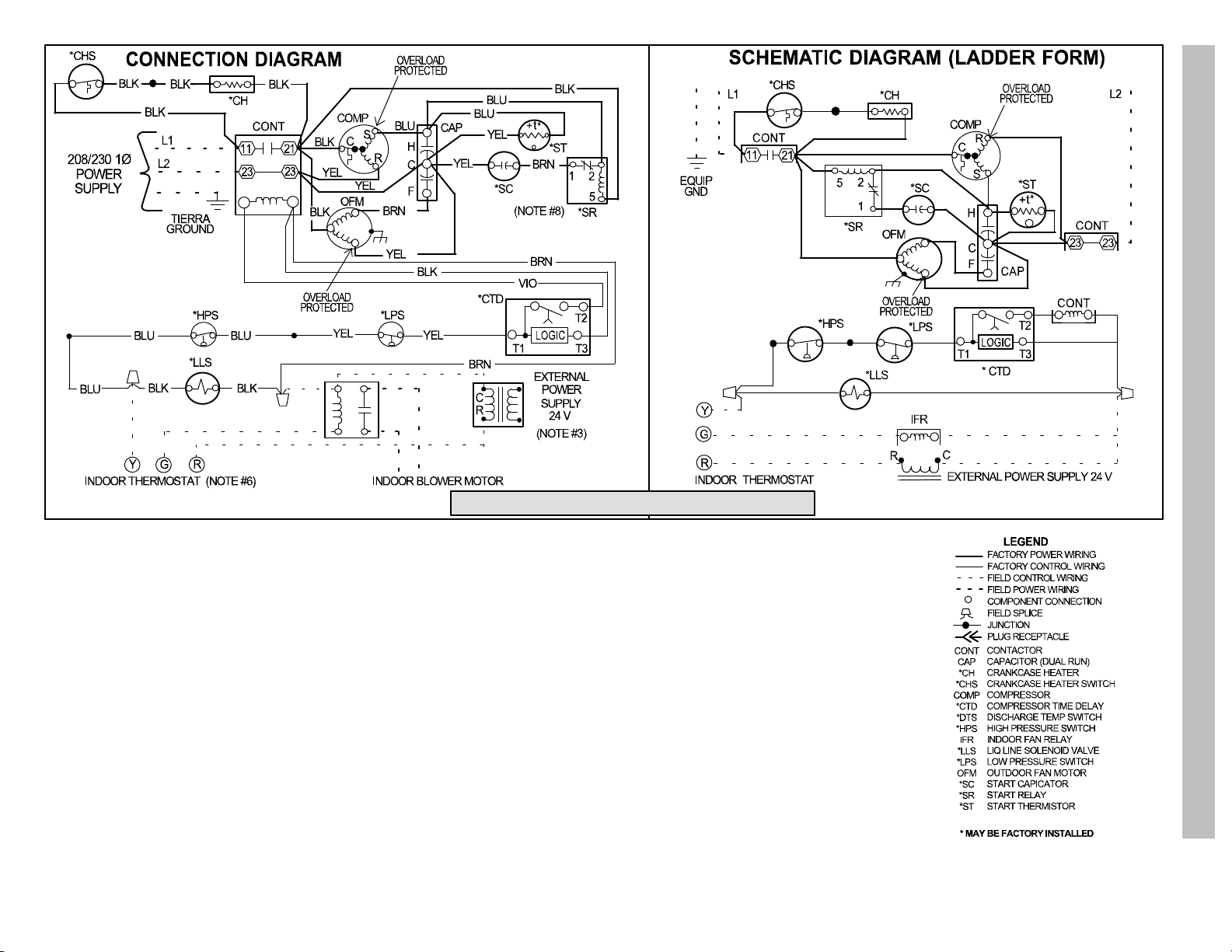
TECHNICAL SUPPORT MANUAL Air Conditioner Component: R2A3**GKR
Model Sizes: 18, 24, 30, 36, 42, 48, 60
1. Symbols are electrical representation only.
2. Compressor and fan motor furnished with inherent thermal protection.
3. To be wired in accordance with National Electric N.E.C. and local codes.
4. N.E.C. class 2, 24 V circuit, min. 40 VA required, 60 VA on units installed with LLS.
5. Use copper conductors only. Use conductors suitable for at least 75°C (167°F).
6. Connection for typical cooling only thermostat. For other arrangements see installation instructions.
7. If indoor section has a transformer with a grounded secondary, connect the grounded side to the BRN lead.
8. When start capacitor and relay are installed, start thermistor (PTC) is not used.
9. If any of the original wire, as supplied, must be replaced, use the same or equivalent wire.
10. Check all electrical connections inside control box for tightness.
11. Do not attempt to operate unit until service valves have been opened.
12. Do not rapid cycle compressor. Compressor must be off 3 minutes to allow pressures to equalize between high and low side before starting.
335780−101 REV. B

TECHNICAL SUPPORT MANUAL Air Conditioner Component: R2A3**GKR
R−22 CHARGING CHART
Rating Plate (required) Subcooling Temperature ° F (° C)
Measured Liquid
Pressure (psig)
163 83 28 78 26 73 23 68 20
171 86 30 81 27 76 24 71 22
179 89 32 84 29 79 26 74 23
187 92 33 87 31 82 28 77 25
196 95 35 90 32 85 29 80 27
205 98 37 93 34 88 31 83 28
214 101 38 96 36 91 33 86 30
223 104 40 99 37 94 34 89 32
233 107 42 102 39 97 36 92 33
243 110 43 105 41 100 38 95 35
253 113 45 108 42 103 39 98 37
264 116 47 111 44 106 41 101 38
274 119 48 11 4 46 109 43 104 40
285 122 50 117 47 112 44 107 42
297 125 52 120 49 115 46 11 0 43
309 128 53 123 51 118 48 11 3 45
° F (° C) ° F (° C) ° F (° C) ° F (° C)
5 3 10 6 15 8 20 11
R−22 Required Liquid Line Temperature ° F (° C)
421 04 6400 00 3

TECHNICAL SUPPORT MANUAL Air Conditioner Component: R2A3**GKR
NOTE: This illustration is for
reference only. Your unit may
differ in appearance or may not
include all components shown.
Please refer to Parts List for
exact parts listing.
Motor
Fan
2
Nut
B
Fan
Guard
L
32
Raceway
Fan
Top Cover
A
3
C
Condenser, Coil
Assembly
Compressor
6
1
Plug, Compressor
Grille
Inlet
F
Panel
Service
Box
D
Control
Box
E
Control.
Cover
T
Barrier
Low Volt
Support
N
9
Coil
Base
Pan
G
Valve Service
Suction
4 421 04 6400 00
7
Valve Service,
Liquid
8
Grommet
R
Lug Ground
11
Bolt, SHLDR (4)
Grommet
10
Compressor
33
Capacitor
4
Contactor
5
P
Strap
Capacitor

TECHNICAL SUPPORT MANUAL Air Conditioner Component: R2A3**GKR
R2A3**GKR PARTS LIST
KEY
NO.
DESCRIPTION PART NO.
R2A318GKR100
R2A324GKR100
R2A330GKR100
R2A336GKR100
R2A342GKR100
R2A348GKR100
01 COMP ZR16K5−PFV−130 ZR16K5PFV130 1 − − − − − −
01 COMP ZR21K5−PFV−130 ZR21K5PFV130 − 1 − − − − −
01 COMP ZR25K5−PFV−130 ZR25K5PFV130 − − 1 − − − −
01 COMP ZR32K5−PFV−130 ZR32K5PFV130 − − − 1 − − −
01 COMP ZR38K5−PFV−130 ZR38K5PFV130 − − − − 1 − −
01 COMP ZR44K5−PFV−130 ZR44K5PFV130 − − − − − 1 −
01 COMP ZR54K5−PFV−130 ZR54K5PFV130 − − − − − − 1
02 MOTOR CONDENSER FAN 1172706 1 1 − − − − −
02 MOTOR CONDENSER FAN 1172707 − − 1 − − − −
02 MOTOR CONDENSER FAN 1172775 − − − 1 − − −
02 MOTOR CONDENSER FAN 1172709 − − − − 1 1 1
03 FAN BLADE 1172027 1 1 − − − − −
03 FAN BLADE 1174760 − − 1 − − − −
03 FAN BLADE 1172713 − − − 1 − − −
03 FAN BLADE 1173854 − − − − 1 1 1
04 CONTACTOR 30 AMP 1172472 1 1 1 1 1 1 −
04 40 AMP 1176763 − − − − − − 1
05 CAPACITOR 370V 30+5 MFD 1172109 1 − − − − − −
05 CAPACITOR 370V 35+5 MFD 1172110 − 1 − − − − −
05 CAPACITOR 370V 40+5 MFD 1172147 − − 1 − − − −
05 50+5 MFD 370V 1172111 − − − 1 − − −
05 55+5 MFD 370V 1172123 − − − − 1 − −
05 60+5 MFD 370V 1172112 − − − − − 1 −
05 80+5 MFD 370V 1172113 − − − − − − 1
06 COIL ASY COND 1179190 1 − − − − − −
06 COIL ASY COND 1179191 − 1 − − − − −
06 COIL ASY COND 1179192 − − 1 − − − −
06 COIL ASY COND 1179193 − − − 1 − − −
06 COIL ASY COND 1179194 − − − − 1 − −
06 COIL ASY COND 1179195 − − − − − 1 −
06 COIL ASY COND 1179196 − − − − − − 1
07 SERVICE VALVE SUCTION 1172726 1 1 1 − − − −
07 SERVICE VALVE SUCTION 1172727 − − − 1 1 1 1
08 SERVICE VALVE LIQUID 1172728 1 1 1 1 1 1 1
09 PLUG COMPRESSOR HARNESS 1172729 1 1 1 − − − −
09 PLUG COMPRESSOR HARNESS 1172730 − − − 1 − − −
09 PLUG COMPRESSOR HARNESS 1172731 − − − − 1 1 −
09 PLUG COMPRESSOR HARNESS 1172732 − − − − − − 1
10 GROMMET COMPRESSOR 1171270 4 4 4 4 4 4 4
11 BOLT COMPRESSOR MOUNTING 1179201 4 4 4 4 4 4 4
32 RACEWAY 1174769 1 1 1 − − − −
32 RACEWAY 1171428 − − − 1 1 1 1
33 LUG GROUND 1172300 1 1 1 1 1 1 1
)( CAP SERVICE KIT 11/16−20 1175650 1 1 1 1 1 1 1
)( CAP SERVICE KIT 15/16−20 1175651 1 1 1 1 − − −
)( CAP SERVICE KIT 1−1/16−20 1175652 − − − − 1 1 1
)( DISTRUBITOR 1172021 − − − − 1 − −
)( DISTRUBITOR 1172022 − − − − − 1 −
− continued on next page −
R2A360GKR100
421 04 6400 00 5

TECHNICAL SUPPORT MANUAL Air Conditioner Component: R2A3**GKR
R2A3**GKR PARTS LIST
KEY
NO.
PART NO.DESCRIPTION
R2A348GKR100
R2A342GKR100
R2A336GKR100
R2A330GKR100
R2A324GKR100
R2A318GKR100
)( DISTRUBITOR 1173667 − − − − − − 1
A PANEL TOP 1176739 1 1 1 − − − −
A PANEL TOP 1176738 − − − 1 1 1 1
B NUT HEX 1172740 4 4 4 4 4 4 4
C GRILLE INLET 1176985 1 − − − − − −
C GRILLE INLET 1176986 − 1 1 − − − −
C GRILLE INLET 1176987 − − − 1 − − −
C GRILLE INLET 1176989 − − − − 1 − −
C GRILLE INLET 1176991 − − − − − 1 −
C GRILLE INLET 1176993 − − − − − − 1
D BOX CONTROL 1179198 1 1 1 1 1 1 1
E KIT COVER CONTROL BOX 1176753 1 1 1 1 1 1 1
F PANEL SERVICE 1176740 1 − − 1 − − −
F PANEL SERVICE 1176741 − 1 1 − − − −
F PANEL SERVICE 1176742 − − − − 1 − −
F PANEL SERVICE 1176744 − − − − − 1 −
F PANEL SERVICE 1176743 − − − − − − 1
G PAN BASE 1176737 1 1 1 − − − −
G PAN BASE 1176764 − − − 1 1 1 1
L GUARD FAN 1179199 1 1 1 − − − −
L GUARD FAN 1179200 − − − 1 1 1 1
N SUPPORT COIL 1174068 3 3 3 5 5 5 5
P STRAP CAPACITOR 1172734 1 1 1 1 − − −
P STRAP CAPACITOR 1172735 − − − − 1 1 1
R GROMMET 1179531 1 1 1 1 1 1 1
T BARRIER LOW VOLTAGE 1176762 1 1 1 1 1 1 1
)( PAINT TOUCH UP 1PT 1174762 1 1 1 1 1 1 1
)( SCREW 10 X 1/2 25 PACK 1174880 1 1 1 1 1 1 1
)( SCREW HEX HD 10AB 3/8 1176782 10 10 10 10 10 10 10
)( SCREW HEX HD 12AB 5/8 1176781 4 4 4 4 4 4 4
R2A360GKR100
International Comfort Products, LLC
Lewisburg, Tennessee 37091 USA
6 421 04 6400 00
 Loading...