

International comfort products N4H424GKF100, WCH4 Series, N4H418GKG101, N4H424GKF200, N4H424GKG101 Wiring Diagram Manual
...
WIRING DIAGRAM MANUAL
Split System Heat Pump
N4H4, R4H4, WCH4
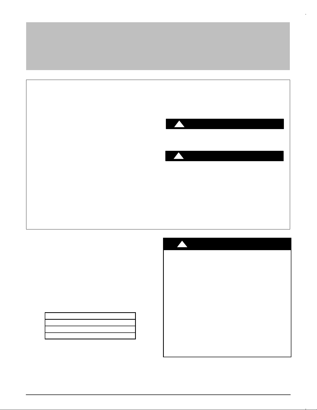
Safety Labeling and Signal Words
DANGER, WARNING, CAUTION, and
NOTE
The signal words DANGER, WARNING, CAUTION, and NOTE are used to identify levels of haz-
ard seriousness. The signal word DANGER is only
used on product labels to signify an immediate hazard. The signal words WARNING, CAUTION, and
NOTE will be used on product labels and throughout this manual and other manuals that may apply
to the product.
DANGER - Immediate hazards which will result in
severe personal injury or death.
WARNING - Hazards or unsafe practices which
could result in severe personal injury or death.
CAUTION - Hazards or unsafe practices which
may result in minor personal injury or product or
property damage.
NOTE - Used to highlight suggestions which will
result in enhanced installation, reliability, or operation.
Signal Words in Manuals
The signal word WARNING is used throughout this
manual in the following manner:
!
The signal word CAUTION is used throughout this
manual in the following manner:
!
Signal Words on Product Labeling
Signal words are used in combination with colors
and/or pictures on product labels.
WARNING
WARNING
CAUTION
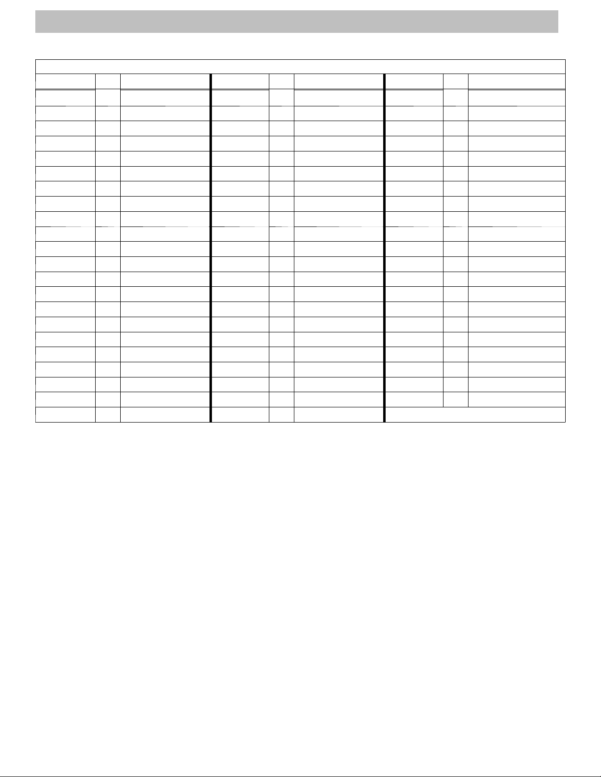
TABLE OF CONTENTS
Expanded Model List 2..................................
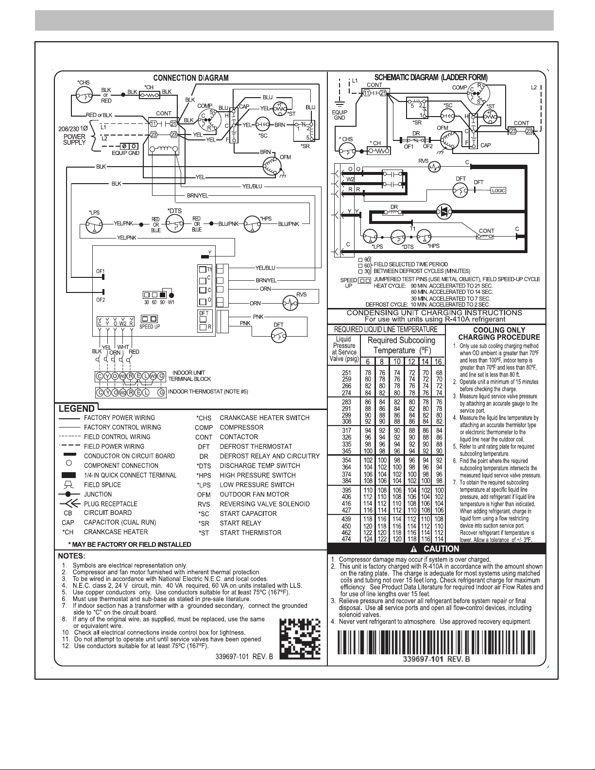
339697- 101 Wiring Diagram 3..........................
339701- 101 Wiring Diagram 4..........................
339903- 101 Wiring Diagram 5...........................
339904- 101 Wiring Diagram 6..........................
343064- 101 Wiring Diagram 7..........................
MODELS
208/230- 1- 60
N4H4
R4H4
WCH4
!
DEATH, PERSONAL INJURY, AND/OR PROPERTY
DAMAGE HAZARD
Failure to carefully read and follow this warning
could result in equipment malfunction, property
damage, personal injury and/or death.
Installation or repairs made by unqualified persons could result in equipment malfunction, property damage, personal injury and/or death.
The information contained in this manual is intended for use by a qualified service technician familiar with safety procedures and equipped with
the proper tools and test instruments.
Installation must conform with local building
codes and with the National Electrical Code
NFPA70 current edition or Canadian Electrical
Code Part 1 CSA C.22.1.
WARNING
Specifications subject to change without notice.
428 03 5203 01 3/21/2019
WIRING DIAGRAM MANUAL Split System Heat Pump
EXPANDED TABLE
DIAGRAM
339697- 101 3 N4H418GKF100 339904- 101
339697- 101 3 N4H418GKF200 339904- 101
339697- 101 3 N4H418GKG101 339904-101
339697- 101 3 N4H424GKF100 339701- 101
339697- 101 3 N4H424GKF200 339904- 101
339701- 101
339697- 101 3 N4H430GKF100 339701- 101
339697- 101 3 N4H430GKF200 339904- 101
339697- 101 3 N4H430GKG101 339904-101
339697- 101 3 N4H436GKF200 339904- 101
339697- 101 3 N4H436GKG101 339904-101
339697- 101 3 N4H437GKG101 339904-101
339697- 101 3 N4H442GKF100 339904- 101
339697- 101 3 N4H442GKF200 339904- 101
339697- 101 3 N4H442GKG101 339904-101
339697- 101 3 N4H448GKF100 339904- 101
339697- 101 3 N4H448GKF200 339904- 101
339697- 101 3 N4H448GKG101 339904-101
339697- 101 3 N4H460GKF100 339904- 101
339697- 101 3 N4H460GKF200 339904- 101
339697- 101 3 N4H460GKG101 339904-101
339904- 101
page
4
6
MODEL DIAGRAM
N4H424GKG101 339904-101
R4H418AKB100 343064- 101
page
6
6
6
4
6
6
4
6
6
6
6
6
6
6
6
6
6
6
6
6
6
7
MODEL DIAGRAM
R4H418GKA100 339903- 101
R4H418GKB100 339697- 101
R4H424AKB100 339697- 101
R4H424AKB101 339903- 101
R4H424GKA100 339904- 101
R4H424GKB100 339904- 101
R4H424GKB101 339904- 101
R4H430AKB100 339904- 101
R4H430GKA100 339701- 101
R4H430GKB100 339904- 101
R4H436AKB100 339904- 101
R4H436GKA100 339904- 101
R4H436GKB100 339904- 101
R4H437AKB100 339904- 101
R4H437GKB100 339904- 101
R4H442AKB100 339904- 101
R4H442GKA100 339904- 101
R4H442GKB100 339904- 101
R4H448AKB100 339697- 101
R4H448GKA100 339697- 101
R4H448GKB100 339903- 101
R4H449GKC100
page
5
4
3
5
6
6
6
6
4
6
6
6
6
6
6
6
6
6
3
3
5
MODEL
R4H460AKB100
R4H460GKA110
R4H460GKA210
R4H460GKB100
WCH4184GKA100
WCH4184GKB100
WCH4244GKA100
WCH4244GKB100
WCH4244GKB101
WCH4304GKA100
WCH4304GKB100
WCH4364GKA100
WCH4364GKB100
WCH4374GKB100
WCH4424GKA100
WCH4424GKB100
WCH4484GKA100
WCH4484GKB100
WCH4604GKA110
WCH4604GKA210
WCH4604GKB100
2 428 03 5203 01
Specifications subject to change without notice.
WIRING DIAGRAM MANUAL Split System Heat Pump
1- Phase 339697- 101
428 03 5203 01 3
Specifications subject to change without notice.
 Loading...