

International comfort products N4H3: C4H3, T4H3, H4H3, N4H4, NXH5 Installation Instructions Manual
...
INSTALLATION INSTRUCTIONS
R−410A Split System Heat Pump
N4H3, C4H3, H4H3, T4H3,
N4H4, NXH5, CXH5, HXH5, TXH5
These instructions must be read and understood completely before attempting installation.
Safety Labeling and Signal Words
DANGER, WARNING, CAUTION, and
NOTE
The signal words DANGER, WARNING,
CAUTION, and NOTE are used to identify levels of
hazard seriousness. The signal word DANGER is
only used on product labels to signify an immediate
hazard. The signal words WARNING, CAUTION,
and NOTE will be used on product labels and
throughout this manual and other manuals that may
apply to the product.
DANGER − Immediate hazards which will result in
severe personal injury or death.
WARNING − Hazards or unsafe practices which
could result in severe personal injury or death.
CAUTION − Hazards or unsafe practices which
may result in minor personal injury or product or
property damage.
NOTE − Used to highlight suggestions which
will result in enhanced installation, reliability, or
operation.
Signal Words in Manuals
The signal word WARNING is used throughout this
manual in the following manner:
WARNING
!
The signal word CAUTION is used throughout this
manual in the following manner:
!
Signal Words on Product Labeling
Signal words are used in combination with colors
and/or pictures on product labels.
WARNING
CAUTION
TABLE OF CONTENTS
Inspect New Unit 2...............................
Safety Considerations 2...........................
Location 2.......................................
Clearances 2 − 3.................................
Unit Support 4...................................
Refrigeration System 5 − 10.......................
Electrical Wiring 10 − 11...........................
Defrost System 12 − 13...........................
Start−up Procedure 14............................
Refrigerant Charge 14 − 17........................
Sequence of Operation 18.........................
Troubleshooting 18...............................
Maintenance 18..................................
Comfort Alertt Diagnostics Codes 19..............
R−410A Quick Reference Guide 20.................
!
DEATH, PERSONAL INJURY, AND/OR PROPERTY
DAMAGE HAZARD
Failure to carefully read and follow this warning
could result in equipment malfunction, property
damage, personal injury and/or death.
Installation or repairs made by unqualified persons could result in equipment malfunction, property damage, personal injury and/or death.
The information contained in this manual is intended for use by a qualified service technician familiar with safety procedures and equipped with
the proper tools and test instruments.
Installation must conform with local building
codes and with the National Electrical Code
NFPA70 current edition or Canadian Electrical
Code Part 1 CSA C.22.1.
WARNING
428 01 5106 00 12/13/12
INSTALLATION INSTRUCTIONS R−410A Split System Heat Pump
INSPECT NEW UNIT
After uncrating unit, inspect thoroughly for hidden
damage. If damage is found, notify the transportation
SAFETY CONSIDERATIONS
Consult a qualified installer, service agency, or the
dealer/distributor for information and assistance. The
qualified installer must use factory authorized kits and
accessories when modifying this product. Refer to the
individual instructions packaged with the kit or accessory
when installing.
The weight of the product requires careful and proper
handling procedures when lifting or moving to avoid
personal injury. Use care to avoid contact with sharp or
pointed edges.
Follow all safety codes. Wear safety glasses, protective
clothing, and work gloves. Use a heat sinking material −
such as a wet rag − during brazing operations. Keep a fire
extinguisher available. Consult local codes and the
National Electric Code (NEC) for special requirements.
Improper installation, adjustment, alteration, service or
maintenance can void the warranty.
company immediately and file a concealed damage
claim.
!
ELECTRICAL SHOCK HAZARD
Failure to turn off the main (remote) electrical disconnect device could result in personal injury or
death.
Before installing, modifying or servicing system,
turn OFF the main (remote) electrical disconnect
device. There may be more than one disconnect
device. Lock out and tag switch with a suitable
warning label.
!
PROPERTY DAMAGE HAZARD
Failure to follow this caution may result in property damage
R−410A systems operate at higher pressures than
R−22 systems. When working with R−410A systems, use only service equipment and replacement components specifically rated or approved
for R−410A service.
WARNING
CAUTION
LOCATION
Check local codes for regulations concerning zoning,
noise, platforms, and other issues.
Locate unit away from fresh air intakes, vents, or
bedroom windows. Noise may carry into the openings
and disturb people inside.
Locate unit in a well drained area, or support unit high
enough so that water runoff will not enter the unit.
Locate unit away from areas where heat, lint, or exhaust
fumes will be discharged onto unit (as from dryer vents).
CLEARANCES
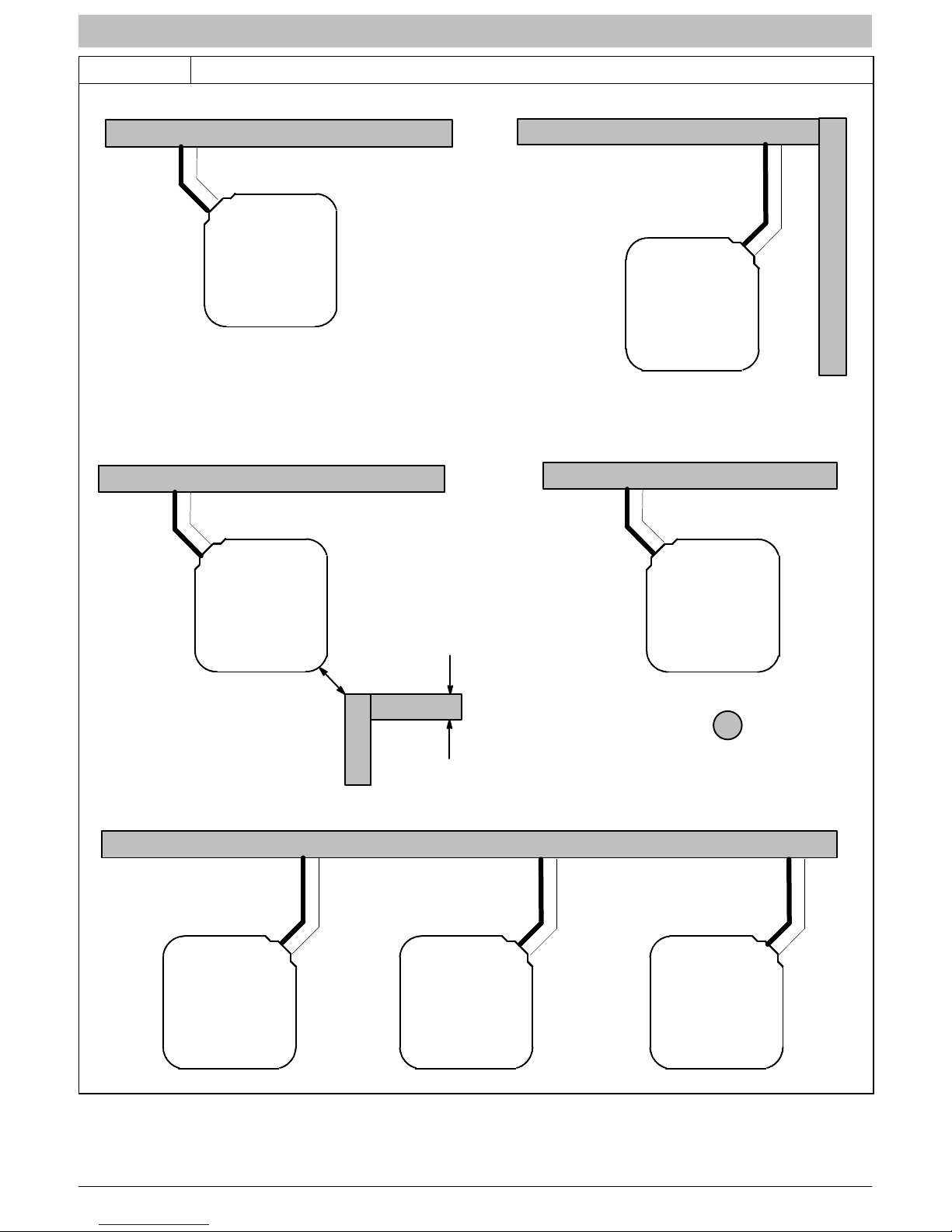
Nominal minimum clearances are 48 inches (1.2m)
above unit for discharge air and 18 inches (457mm) on
each side of the coil for intake air. Clearance on any one
side of the coil (normally between unit and structure) may
be reduced to 6 inches (152mm). Nominal minimum
clearances are based on a solid parallel object such as a
wall or roof overhang.
The clearance may be reduced for a single object with
small surface area, such as the end of a wall, outside
corner of a wall, fence section, post, etc. As a general
rule, the minimum clearance from the unit should equal
the width of the object. For example, a 6 inch (152mm)
fence post should be a minimum of 6 inches (152mm)
from the unit.
Locate unit away from recessed or confined areas where
recirculation of discharge air may occur (refer to
CLEARANCES section of this document).
Roof−top installation is acceptable providing the roof will
support the unit and provisions are made for water
drainage and noise/vibration dampening.
NOTE: Roof mounted units exposed to wind may require
wind baffles. Consult the manufacturer for additional
information.
Do not install unit under roof overhangs unless gutters are
present. A minimum vertical clearance of 48 inches
(1.2m) is required to the overhang.
Inside corner locations on single story structures require
evaluation. Large overhanging soffits may cause air
recirculation in a corner area even though recommended
minimum clearances are maintained. As a guide, locate
the unit far enough out so that half of the discharge grille is
out from under the soffit.
When placing two or more units side−by−side, provide a
minimum of 18 inches (457mm) between units.
Provide minimum service clearance of 24 inches
(610mm) from control box corner and side service panel.
Refer to Figure 1.
2 428 01 5106 00
INSTALLATION INSTRUCTIONS R−410A Split System Heat Pump
Figure 1 Clearances (various examples)
24”
(610mm)
Service
Wall
6”
(152mm)
18”
(457mm)
Wall
6”
(152mm)
18”
(457mm)
18”
(457mm)
Wall
24”
(610mm)
Service
Wall
6”
(152mm)
18”
(457mm)
Wall
6”
(152mm)
24”
(610mm)
Service
18”
(457mm)
24”
(610mm)
Service
4”
(102mm)
(457mm)
18”
(152mm)
18”
(102mm)
wide fence
Wall
24”
(610mm)
Service
4”
24”
(610mm)
Service
18”
(457mm)
18”
(457mm)
6”
(152mm)
6”
(152mm)
Post
24”
(610mm)
Service
18”
(457mm)
428 01 5106 00 3
INSTALLATION INSTRUCTIONS R−410A Split System Heat Pump
UNIT SUPPORT
NOTE: Unit must be level | 2 degrees {a inch rise or fall
per foot of run (10mm rise or fall per 305 mm of run) } or
compressor may not function properly.
A. GROUND LEVEL INSTALLATION
The unit must be level and supported above grade by
beams, platform, or a pad. Platform or pad can be of open
or solid construction but should be of permanent
materials such as concrete, bricks, blocks, steel, or
pressure− treated timbers approved for ground contact.
Soil conditions must be considered so that the platform or
pad does not shift or settle and leave the unit partially
supported. Minimum pad dimensions are shown in
Figure 2.
If beams or an open platform are used for support, it is
recommended that the soil be treated or area be graveled
to reduce the growth of grasses and weeds.
To minimize vibration or noise transmission, it is
recommended that supports not be in contact with the
building structure. However, slabs on grade constructions
with an extended pad are normally acceptable.
!
CAUTION
!
CAUTION
PROPERTY DAMAGE HAZARD
Failure to follow this caution may result in property damage.
Inadequate unit support may cause excessive vibration,
noise, and/or stress on the refrigerant lines, leading to refrigerant line failure.
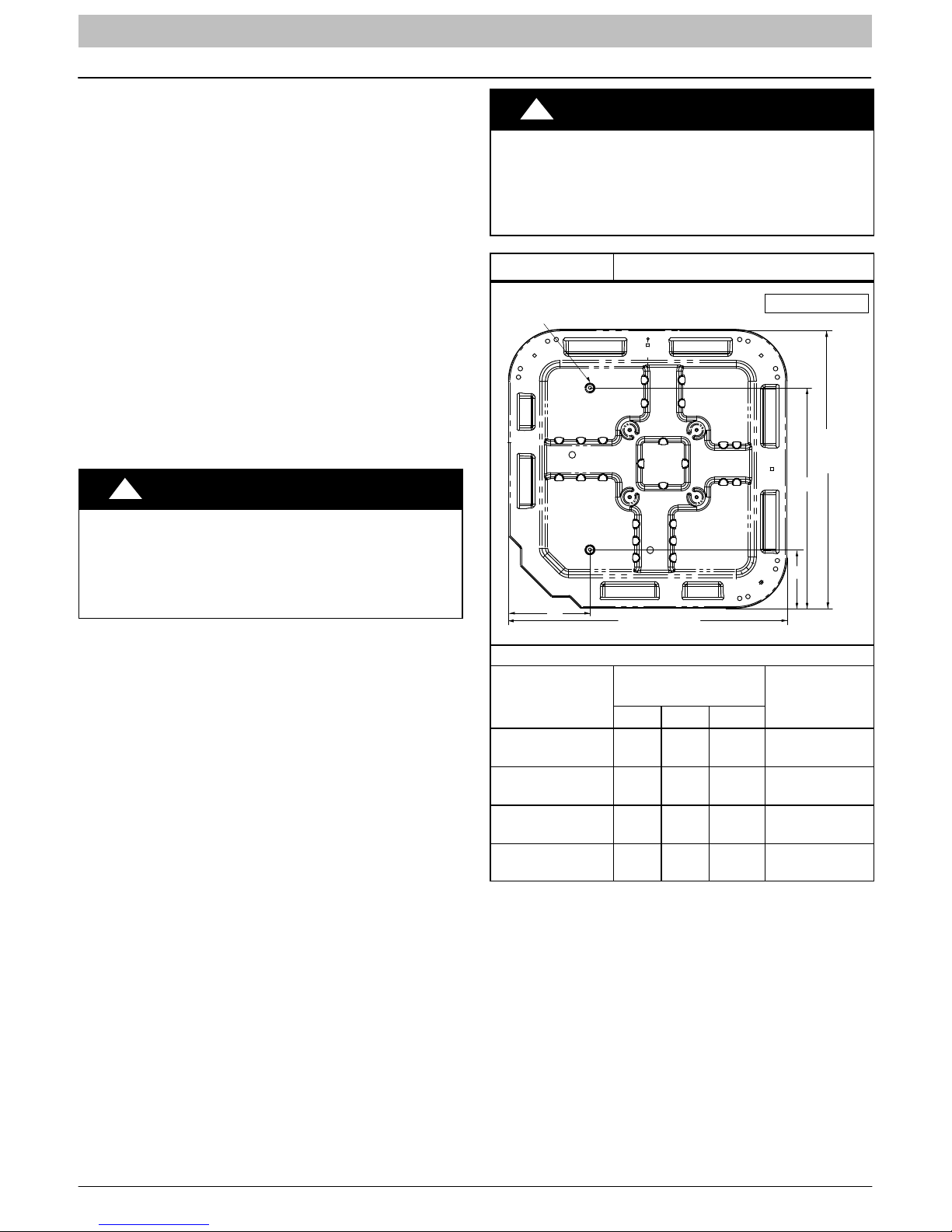
Figure 2 Tie Down Knockouts
a” (10mm) dia. Tie Down Knockouts
In Base Pan (2 places)
View From Top
Base
Pan
Depth
C
PROPERTY DAMAGE HAZARD
Failure to follow this caution may result in property damage.
Top surface of platform must be above estimated snowfall level to prevent snow blocking coil and to allow water
melt to drain from unit.
B. ROOF TOP INSTALLATION
This type of installation is not recommended on wood
frame structures where low noise levels are required.
Supporting structure or platform for the unit must be level.
If installation is on a flat roof, locate unit minimum 6 inches
(152mm) above roof level.
Place the unit over one or more load bearing walls. If there
are several units, mount them on platforms that are
self−supporting and span several load bearing walls.
These suggestions are to minimize noise and vibration
transmission through the structure. If the structure is a
home or apartment, avoid locating the unit over
bedrooms or study.
NOTE: When unit is to be installed on a bonded
guaranteed roof, a release must be obtained from the
building owner to free the installer from all liabilities.
C. FASTENING UNIT DOWN
If conditions or local codes require the unit be attached in
place, remove the knockouts in the base pan and install
tie down bolts through the holes (refer to Figure 2).
Contact local distributor for hurricane hold−down details and
the P.E. (Professional Engineer) certification, when
required.
A
Base Pan
Width x Depth
@# ~ @#
(584 x 584)
@%n ~ @%n
(652 x 652)
#!8 ~ #!8
(791 x 791)
#$, ~ #$,
(887 x 887)
Base Pan Width
Inches (mm)
Tie Down
Knockouts
A B C
&w
(197)$v(113)!*(457)
(z
(230)$v(113)
(z
(230)^2(165)
(z
(230)^2(165)
@!4
(540)
@$s
(625)
@*v
(722)
B
Minimum
Mounting Pad
Dimensions
@# X~ @#
(584 x 584)
@^ X~ @^
(660 x 660)
#!2 ~ #!2
(800 x 800)
#% ~ #%
(889 x 889)
4 428 01 5106 00
INSTALLATION INSTRUCTIONS R−410A Split System Heat Pump
REFRIGERATION SYSTEM
A. COMPONENT MATCHES
Check to see that the proper system components are in
place, especially the indoor coil.
R−410A outdoor units can only be used with R−410A
specific indoor coils. If there is a refrigerant mis−match,
consult the indoor coil manufacturer to determine if a
refrigerant conversion kit is available for the indoor coil.
This outdoor unit is designed to achieve maximum
efficiency when used with indoor coils that utilize a TXV
refrigerant metering device or Piston with Teflon ring
metering device. If any other type of metering device is
installed on the indoor coil, consult the indoor coil
manufacturer to determine if a conversion kit is available.
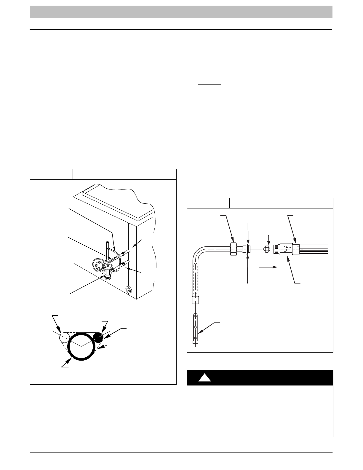
Installing with TXV.
When installing a TXV on an indoor coil, follow the
instructions provided with the new TXV.
A typical TXV installation is shown in Figure 3.
Figure 3 Typical TXV Installation
INDOOR
COIL
EQUALIZER
TUBE
Installing with Indoor Piston − cooling operation.
(Heat pumps also use an outdoor piston for heating
operation, refer to section F.)
Check piston size shipped with indoor unit to see if it
matches required indoor piston size shown on outdoor
unit rating plate.
If it does not match, replace indoor piston with cooling
piston, according to size marked on outdoor unit rating
plate. (Some outdoor models include a cooling piston in
the accessory bag.)
Heating piston is shipped in the service valve − refer to
section F.
Example fan coils with piston: FEM4P, FSM4P, FSU4P.
See Figure 4.
When changing indoor piston, use a back−up wrench.
Hand tighten hex nut, then tighten with wrench 1/2 turn.
Do not exceed 30 ft−lbs.The indoor piston contains a
Teflon ring (or seal) which is used to seat against the
inside of distributor body, and must be installed properly
to ensure proper seating in the direction for cooling
operation.
Figure 4 Indoor (cooling) Piston
BRASS
HEX NUT
TEFLON SEAL
DISTRIBUTOR
SENSING
BULB
TXV
10 O’Clock
7/8
2 O’Clock
SUCTION TUBE
IN. OD & SMALLER
STRAP
SUCTION
TUBE
LIQUID
TUBE
SENSING BULB
TEFLON RING
PISTON
FLOW IN
COOLING
PISTON
RETAINER
STRAINER
BRASS
HEX BODY
L10S017
!
PRODUCT OPERATION HAZARD
Failure to follow this caution may result in improper product
operation.
If using a TXV in conjunction with a single−phase reciprocating compressor, a compressor start capacitor and relay are
required. Consult outdoor unit pre−sale literature for start assist kit part number.
CAUTION
428 01 5106 00 5
INSTALLATION INSTRUCTIONS R−410A Split System Heat Pump
B. REFRIGERANT LINE SETS
The refrigerant line set must be properly sized to assure
maximum efficiency and proper oil circulation.
Refer to Product Specifications and Long Line
Applications Guideline for line set sizing.
NOTE: Total line set length must not exceed 200 feet
(61m).
NOTE: A crankcase heater must be used when the
refrigerant line length exceeds 80 feet (24.4m).
If outdoor unit is more than 10 feet (3m) higher than the
indoor coil, refer to the Long Line Applications Guideline
for instructions.
NOTE: When the outdoor unit is higher than the indoor
coil, the vertical separation must not exceed 100 feet
(30m).
NOTE: When the outdoor unit is lower than the indoor
coil, the vertical separation must not exceed 50 feet
(15.2m).
If it is necessary to add refrigerant line in the field, use
dehydrated or dry, sealed, deoxidized, copper
refrigeration tubing. Do not use copper water pipe.
Do not remove rubber plugs or caps from copper tubing
until connections are ready to be made.
Be extra careful when bending refrigeration tubing.
Tubing can “kink” easily, and if this occurs, the entire
length of tubing must be replaced.
!
PERSONAL INJURY HAZARD
Failure to relieve system pressure could result in
personal injury and/or death.
Relieve pressure and recover all refrigerant before
servicing existing equipment, and before final unit
disposal. Use all service ports and open all flow−
control devices, including solenoid valves.
!
UNIT OPERATION HAZARD
Failure to follow this caution may result in improper product operation.
Do not leave system open to atmosphere any longer than absolutely required for installation. Internal system components − especially refrigerant
oils − are extremely susceptible to moisture contamination. Keep ends of tubing sealed during
installation until the last possible moment.
WARNING
CAUTION
6 428 01 5106 00
INSTALLATION INSTRUCTIONS R−410A Split System Heat Pump
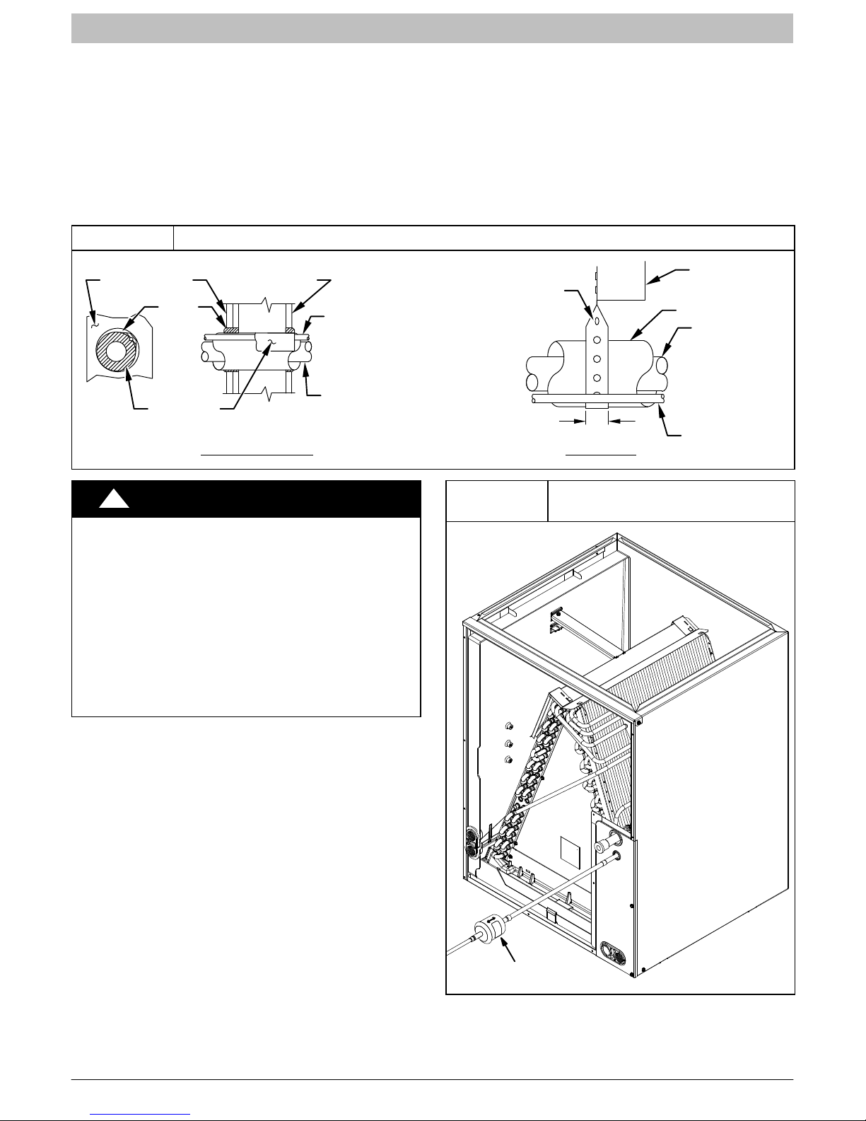
C. ROUTING AND SUSPENDING REFRIGERANT
LINES
Run refrigerant lines as straight and direct as possible,
avoiding unnecessary bends and turns. Always insulate
the entire suction line. Both lines should be insulated
when routed through an attic or when routed through an
underground raceway.
When routing refrigerant lines through a foundation or
wall, do not allow refrigerant lines to come in direct
contact with the building structure. Make openings large
Figure 5
OUTDOOR WALL INDOOR WALL
CAULK
INSULATION
THROUGH THE WALL SUSPENSION
Routing and Suspending Refrigerant Lines
LIQUID TUBE
SUCTION TUBE
enough so that lines can be wrapped with extra insulation.
Fill all gaps with RTV caulk. This will prevent noise
transmission between the tubing and the foundation or
wall.
Along floor or ceiling joists, suspend refrigerant lines so
that they do not contact the building structure, water
pipes, or ductwork. Use insulated or suspension type
hangers. Metal straps must be at least 1” (25mm)wide to
avoid cutting into the tube insulation. Keep the liquid and
suction lines separate. Refer to Figure 5.
JOIST
HANGER STRAP
(AROUND SUCTION
TUBE ONLY)
1” (25mm) MIN
INSULATION
SUCTION TUBE
LIQUID TUBE
!
CAUTION
UNIT OPERATION HAZARD
Failure to follow this caution may result in improper product operation.
Do not bury more than 36” (1m) of line set underground. Refrigerant may migrate to cooler buried
section during extended periods of unit shut−
down, causing refrigerant slugging and possible
compressor damage at start−up.
If ANY section of the line set is buried underground, provide a minimum 6” (152mm) vertical
rise at the service valve.
D. OUTDOOR UNIT HIGHER THAN INDOOR UNIT
Proper oil return to the compressor should be maintained
with suction gas velocity. If velocities drop below 1500
fpm (feet per minute), oil return will be decreased. To
maintain suction gas velocity, do not upsize vertical
suction risers.
E. LIQUID LINE FILTER−DRIER
Outdoor units are shipped with an appropriate filter−drier
for installation in the liquid line. Leave the plugs in the tube
ends until the filter−drier is installed. The optimal location
for the filter−drier is close to the indoor coil. Heat pump
filter−driers are “bi−flow” type. Either end can be pointed
towards indoor coil. Refer to Figure 6.
Figure 6
Liquid Line Filter−Drier
Installed at Indoor Coil
428 01 5106 00 7
Filter−Drier
38−11 −84
 Loading...