

International Comfort Products MF08B1500B1, MF12F1900B1, MF16J2200B1, MF20L2400B1 Installation Manual
INSTALLATION INSTRUCTIONS
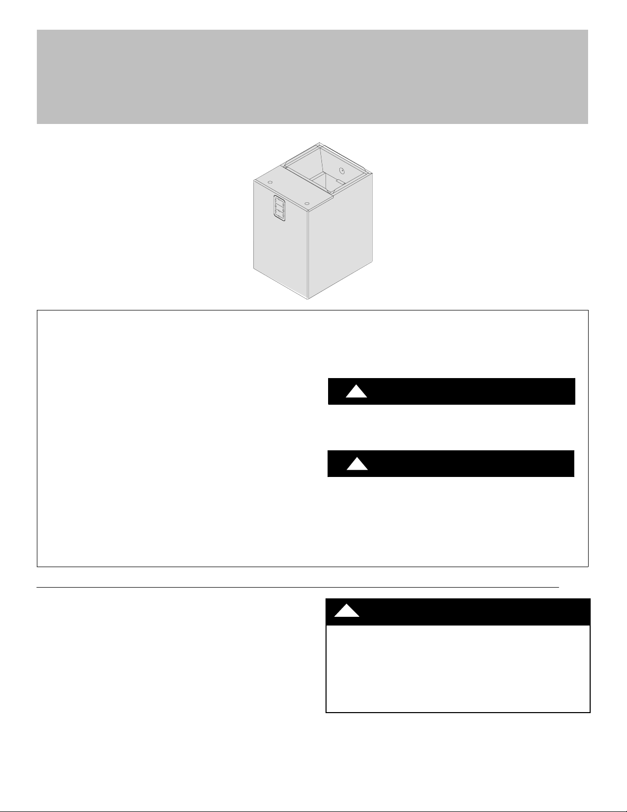
Modular Blower (Electric Furnace)
MF08B1500B1, MF12F1900B1, MF16J2200B1, MF20L2400B1
These instructions must be read and understood completely before attempting installation.
Safety Labeling and Signal Words
DANGER, WARNING, CAUTION, and NOTE
The signal words DANGER, WARNING, CAUTION, and
NOTE are used to identify levels of hazard seriousness.
The signal word DANGER is only used on product labels
to signify an immediate hazard. The signal words
WARNING, CAUTION, and NOTE will be used on
product labels and throughout this manual and other
manuals that may apply to the product.
DANGER -- Immediate hazards which will result in
severe personal injury or death.
WARNING -- Hazards or unsafe practices which could
result in severe personal injury or death.
CAUTION -- Hazards or unsafe practices which may
result in minor personal injury or product or property
damage.
NOTE -- Used to highlight suggestions which will result in
enhanced installation, reliability, or operation.
TABLE OF CONTENTS
General Information/Installation 2..................
Installation 2.....................................
Vertical/Horizontal Installation 3....................
Ductwork Connection 4...........................
Filter Installation 4................................
Electrical Connection 4...........................
Blower Performance 8............................
Sequence of Operation 9..........................
Wiring Diagram 10...............................
Replacement Parts 12............................
Signal Words in Manuals
The signal word WARNING is used throughout this
manual in the following manner:
WARNING
!
The signal word CAUTION is used throughout
this manual in the following manner:
!
Signal Words on Product Labeling
Signal words are used in combination with colors and/
or pictures on product labels.
!
ELECTRICAL SHOCK HAZARD
Failure to turn off electric power could result in personal injury or death.
Before installing or servicing system, turn off main
power to the system. There may be more than one disconnect switch, including accessory heater(s).
WARNING
CAUTION
WARNING
442 01 2205 01 Jan 2008
MODULAR BLOWER: MFINSTALLATION INSTRUCTIONS
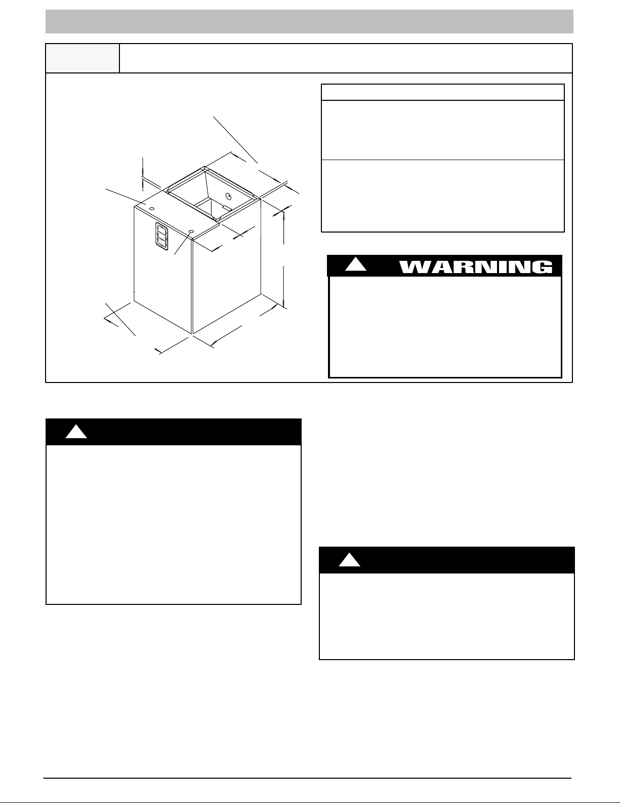
Figure 1
Low Voltage
Entrance
15w (2--22 Ton)
194 (3--32 Ton)
22d (4 Ton)
242 (5 Ton)
Nominal Installation Dimensions and Clearances
14a (2 -- 22 Ton)
17d (3 -- 32 Ton)
212 (4 Ton)
238 (5 Ton)
3/4”
8
Line Voltage
Entrance
ALL DIMENSIONS IN INCHES
1IN=25.4MM
12”
1
/2”
24”
1
20
/2”
NO HEATERS
All Sides 0”..................................
From Supply Duct 0”..........................
Recommended Service From Front 20”(508 mm)..........
(Service for blower, filter if installed)
WITH HEATERS
All Sides 0”..................................
From First Three Feet of Supply Duct
5/8”
to Combustibles 1”...........................
From Duct after Three Feet 0”.................
Recommended Service From Front 20” (508mm)..........
(Service for blower, heaters if installed)
CLEARANCES
!
FIRE HAZARD
Failure to follow this warning could result in
personal injury, death, and/or property damage.
When heaters are installed maintain clearances
from combustible materials as specified on unit
rating plate. Do not use plastic lined or combustible
flexible ducting within 36’’ (914 mm) of the supply
end of the modular unit.
GENERAL INFORMATION
!
PERSONAL INJURY, AND/OR PROPERTY DAMAGE
HAZARD
Failure to carefully read and follow this warning
could result in personal injury, death, equipment
malfunction, and/or property damage.
The information contained in this manual is intended for use by a qualified service technician familiar with safety procedures and equipped with the
proper tools and test instruments.
Installation must conform with local building codes
and with the National Electrical Code NFPA70 current edition.
INTRODUCTION
The MF modular blower cabinet uses a 208/230V PSC blower
motor, with an electronic fan control board. The MF may be used
for cooling or heat pump applications either with or without electric
heat. Installations without electric heat require a NO HEAT KIT
(EHIA00KN10). The cabinet can be installed in an upflow,
downflow or horizontal position. Refer to Figure 3 and 4.
LOCATION
Select the best position which suits the installation site conditions.
The location should provideadequatestructural support, space in
the front of the unit for service access, clearance for return air and
supply duct connections, space for refrigerant piping connections
and condensate drain line connections. If heaters are being
WARNING
installed, make sure adequate clearance is maintained from
supply ductwork, See Clearances and Warning in Figure 1.
If the unit is located in an area of high humidity, nuisance sweating
of casing may occur. On these installations a wrap of 2” (51mm)
fiberglass insulation with a vapor barrier should be used.
HEATER PACKAGES
Factory approved, field installed, UL listed heater packages are
available from the equipment supplier. See unit rating plate for a
list of factory approved heaters (electric heat accesso ry models
EHIA only). Heaters that are not factory approved could cause
damage which would not be covered under the equipment
warranty.
!
CAUTION
CUT HAZARD
Failure to follow this caution may result in personal
injury .
Sheet metal parts may have sharp edges or burrs.
Use care and wear appropriate protective clothing
and gloves when handling parts.
INSTALLATIONS
The unit is ready to install in any position without modifications.
Refer to the co il instructions for information on drain pan
configurations etc. Make sure coil is set up properly for desired
position of blower cabinet.
Coil must be secured to blower cabinet with the three tabs that are
part of the blower cabinet base. Bend the tabs out from the bottom
so they fit over the coil cabinet.
Position coil cabinet in relation to the blower so they will be correct
for desired application.
2
442 01 2205 01
MODULAR BLOWER: MF
INSTALLATION INSTRUCTIONS
For upflow and horizontal applications apply foam seal strip
around top of coil cabinet. For downflow application apply foam
seal strip around bottom of coil cabinet. Set blower on top of coil
cabinet so they are flush. Secure cabinets together using the
three tabs on the bottom of the cabinet. Bend the tab out from the
bottom so it fits over the coil cabinet. If no pilot holes are present,
drill a hole as required for a screw.
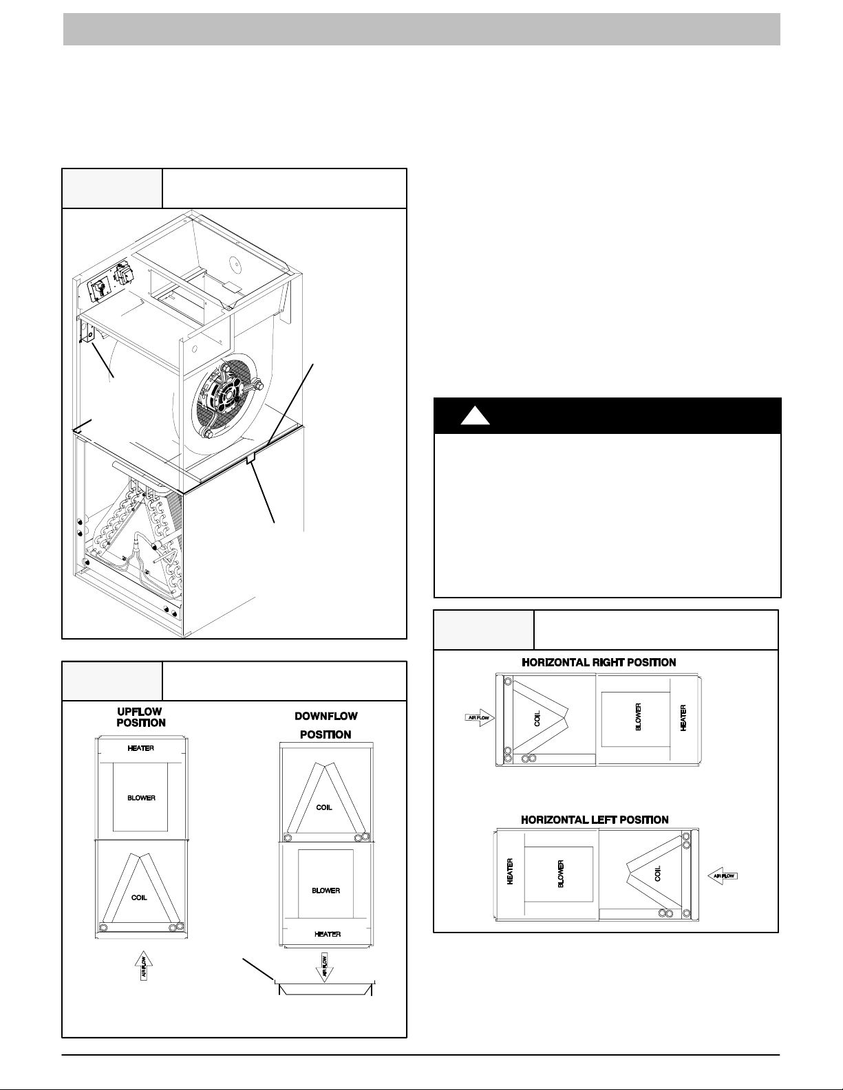
Figure 2
Attach Coil to Blower Cabinet
Panels removed
for clarity only
Place seal
on top of
Coil Cabinet
Low
voltage
around
perimeter
wiring
splice box
Bend Tabs (both sides
and back) on Bottom of
Blower Cabinet to Fit
over Coil Cabinet
DOWNFLOW INSTALLATIONS
Refer to instructions with Subbase Kit.
NON-DUCTED RETURN AIR CLOSET
INSTALLATION
Thecabinetcanbeinstalledinaclosetwithafalsebottomtoform
a return air plenum, or mounted on an open platform inside the
closet. Platform should be high enough to provide a free (open)
area for adequate return airflow into the bottom of the cabinet.
The open area can be on the front side or a combination of front
and sides, providing there is clearance on the sides between
cabinet and closet.Refer to ACCA Manual D for sizing and free
area recommendations.
NOTE: Local codes may limit application of systems without a
ducted return to single story dwellings.
HORIZONTAL LEFT AND RIGHT
INSTALLATIONS
The modular blower cabinets can be installed in either downflow,
horizontal left, or horizontalrightapplications. When a coil cabinet
is applied, refer to the coil installation manual for proper drain pan
and airflow requirements. They must have the drain pan
repositioned for right hand airflow. Refer to coil installation
manual.
!
PROPERTY DAMAGE HAZARD
Failure to follow this caution may result in property
damage.
A field fabricated auxiliary drain pan, with a separate
drain is REQUIRED for all installations over a finished living space or in any area that may be damaged by overflow from a restricted main drain pan.
In some localities, local codes require an auxiliary
drain pan for ANY horizontal installation.
CAUTION
Figure 3
Airflow Positions
Subbase
Accessory
Figure 4
Airflow Positions
SUSPENDED CABINET INSTALLATION
1. The cabinet may be supported on a frame or shelf, or it may
be suspended.
2. Use metal strapping or threaded rod with angle iron
supports under the auxiliary drain pan to suspend cabinet.
These supports MUST run parallel with the length of the
cabinet. Refer to Figure 5.
442 01 2205 01
3
MODULAR BLOWER: MFINSTALLATION INSTRUCTIONS
3. Ensure that there is adequate room to remove service and
access panels after installing supporting brackets.
4. Place field installed vibration isolators in auxiliary drain pan
to support cabinet.
DUCT CONNECTIONS
Supply Duct
Supply duct must be attached to the outside of flange on outlet
end of unit. Flexible connectors may be used if desired. Maintain
clearances from supply duct to combustibles when heaters are
installed. Refer to Figure 1 and unit rating plate.
Return Duct
Return duct should be attached to bottom of unit using sheet
metal screws or other fasteners.
FILTER INSTALLATION
Filters must be field supplied. A remote filter grille or other means
must be provided. Refer to ACCA Manual D for remote filter
sizing.
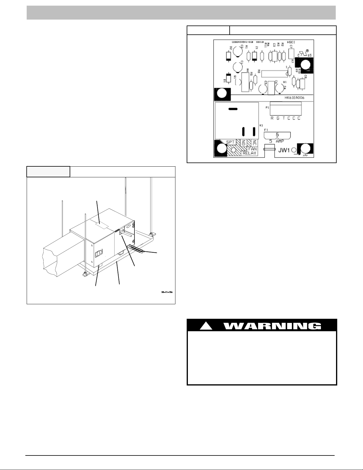
Figure 5
Supports MUST run parallel with blower cabinet
Horizontal Installation
See Note
Below
Refrigerant
Lines
Vibration
Isolators
Field-Fabricated
Drain Pan
Drain
Lines
Figure 6 Fan Control Board
All electrical work MUST conform with the requirements of local
codes and ordinances and the National Electrical Code NFPA 70
current edition.
The low voltage transformer and the fan control are standard on
all models and are prewired at the factory. Line voltage
connections are made to the heater accessory or the lugs on the
No Heat Kit.
OVERCURRENT PROTECTION
The power supply wiring to the unit MUST be provided with
overcurrent protection. Governing codes may require this to be
fuses ONLY or circuit breakers.
For blower cabinets without heaters, a 15 amp circuit may be
used.
Before proceeding with electrical connections, make certain that
supply voltage, frequency, phase, and circuit ampacity are as
specified on the unit rating plate. See unit wiring label for proper
field high and low voltage wiring. Make all electrical connections
in accordance with the NEC and any local codes or ordinances
that may apply. Use copper wire only. The unit must have a
separate branch electric circuit with a field--supplied disconnect
switch located within sight from and readily accessible from the
unit.
NOTE: When a pull--out type disconnect is removed from the unit,
only the Load side of the circuit is de--energized. The Line side
remains live until the main (remote) disconnect is turned off.
NOTE: If increased structural strength is needed in the horizontal position, use field supplied two connecting plates in
place of the tabs on the bottom of the blower.
ELECTRICAL CONNECTIONS
The MF modular blower utilizes an electronic fan control board
which has a low voltage circuit protective fuse (5 AMP), and pigtail
connections for thermostat hook up. The fan control also has a
relay for blower operation, and built in 90 second blower--off time
delay relay (TDR). To disable the TDR feature, snip the jumper
wire JW1. Refer to Figure 6.
4
!
ELECTRICAL SHOCK or UNIT DAMAGE HAZARD
Failure to follow this warning could result in personal injury, death, and/or property damage.
If a disconnect switch is to be mounted on unit,
select a location where drill and fasteners will not
contact electrical refrigeration components.
442 01 2205 01

MODULAR BLOWER: MF
!
ELECTRICAL SHOCK or UNIT DAMAGE HAZARD
Failure to follow this warning could result in personal injury, death, and/or property damage.
Turn OFF electric power at fuse box or service
panel before making any electrical connections
and ensure a proper ground connection is made
before connecting line voltage.
!
ELECTRICAL SHOCK HAZARD
Failure to follow this warning could result in personal injury or death.
Turn off the main (remote) disconnect device before working on incoming (field) wiring. Incoming
(field) wiring on the line side of the disconnect
found in the modular blower unit remains live,
even when the pull--out is removed. Service and
maintenance to incoming (field) wiring cannot be
performed until the main disconnect switch (remote to the unit) is turned off.
INSTALLATION INSTRUCTIONS
NOTE: Transformer is factory--wired for 230V operation. For
208V applications the transformer must be rewired to the 208V
tap. Refer to unit wiring label.
GROUNDING CONNECTION
Use a copper conductor(s) from the ground lug on the No Heat Kit
or ground lugs on the electric heater to a grounded connection in
the electric service panel or a properly installed grounding rod.
LOW VOLTAGE CONTROL CONNECTIONS
Wire low--voltage in accordance with wiring label on the blower
(also refer to Figures 8 -- 12. Use 18 AWG color--coded,
insulated (35°C minimum) wire to make the low--voltage
connections between: thermostat, indoor equipment, and
outdoor equipment. If thermostat is located more than 100 feet
from the unit (as measured along the low voltage wire), use 16
AWG color--coded, insulated (35° C minimum) wire. All wiring
must be NEC Class 1 and must be separated from incoming
power leads. Refer to outdoor unit wiring instructions for
additional wiring recommendations.
Field supplied low--voltage wiring should be field connected
inside control splice box area (secure with wire nuts), and strain
relief bushing or rubber grommet to seal cabinet opening.
Electrical ControlsFigure 7
Low Voltage
Connections
MF units installed without electric heat require the use of a
factory--authorized No Heat Kit (accessory part number
EHIA00KN10). This kit provides the electrical connections
necessary to supply the unit with 208/230V power when electric
heat is not present.
For units without electric heat:
1. Locate adapter and filler plates with screws inside
package. If necessary, adjust plates to allow for
installation of No Heat Kit required inside cabinet. Refer
to Figure 7.
2. Secure No Heat Kit accessory with four (4) screws.
3. Connect the 9--pin plug from No Heat Kit wiring into the
receptacle that attaches to fan control board.
4. Connect ground wire to unit ground lug.
5. Connect 208/230V power leads from field disconnect to
terminal block assembly on No Heat Kit.
For units with electric heat, see Electric Heater Installation
Instructions and blower airflow requirements.
Supply Circuit
Supply
Tab l e 1
MF08*
MF12*
MF16*
MF20*
* Modular blower without electric heat Conversion: 1 ft = .305 meter
Volts Phase Hertz
208
230
208
230
208
230
208
230
1 60 Single 1/3 2.5 3.1 15 2 14 105 1 14
1 60 Single 1/2 2.9 3.6 15 2 14 105 1 14
1 60 Single 1/2 2.9 3.6 15 2 14 105 1 14
1 60 Single 3/4 6.0 7.5 15 2 14 90 1 14
Circuit
No.
H.P.
Max.
Motor
Amps
MCA
Branch
Circuit
AMP
Filler Plate
Adapter Plate
No Heat Kit
Max Over-current
Protection
Devise
(Amps)
Lugs for
Line Voltage
and Ground
Connections
Supply Wire
75°C copper
#of
Wires
Control Splice Box
Recommended
Min
Max. Ft.
Size
Length
Ground Wire
#of
Wires
Min
Size
442 01 2205 01
5

MODULAR BLOWER: MFINSTALLATION INSTRUCTIONS
Figure 8
THERMOSTAT
R
G
W
Y
Figure 9
THERMOSTAT
R
G
W
Y
Figure 10
Wiring Layout Air Conditioning Unit
(Cooling Only)
RED
GRY
WHT
WHT
PINK
VIO
BRN
R
G
W
2
W
3
E
C
AIR COND.
Wiring Layout Air Conditioning Unit
(Cooling and Single--Stage Heat)
RED
GRY
WHT
WHT
PINK
VIO
BRN
R
G
W
2
W
3
E
C
AIR COND.
Wiring Layout Heat Pump Unit
(Cooling and Single--Stage Heat
with No Outdoor Thermostat)
Wiring Layout Heat Pump Unit
Figure 11
(Cooling and Two--Stage Heat with
One Outdoor Thermostat)
THERMOSTAT
RED
GRY
BRN
WHT
VIO
PINK
R
G
C
W
2
E
W
ODTS
3
R
G
C
W
2
E
C
Y
L
O
Y
HEAT PUMP
(CONTROL)
R
C
W
2
O
Y
Wiring Layout Heat Pump Unit
Figure 12
(Cooling and Two--Stage Heat with
Two Outdoor Thermostats)
THERMOSTAT
RED
GRY
BRN
WHT
VIO
PINK
R
G
C
W
2
E
W
ODTS
3
ODTS
R
G
C
W
C
Y
2
E
L
HEAT PUMP
(CONTROL)
R
C
W
2
THERMOSTAT
R
G
C
W
2
E
L
O
Y
6
RED
GRY
BRN
WHT
PINK
VIO
HEAT PUMP
(CONTROL)
R
G
C
W
2
W
3
E
R
C
W
2
O
Y
O
Y
O
Y
442 01 2205 01

MODULAR BLOWER: MF
INSTALLATION INSTRUCTIONS
CHANGING MOTOR SPEED
To change the blower speed, disconnect the black wire at the
blower motor terminal block and reconnect at the desired blower
speed tap (refer to Ta ble 4 ).
HEATER STAGING
The modular controls are factory circuited for single--stage
electric heat operation. Refer to Ta b l e 2 for available heaters and
Tab l e 3 for unit airflow based without a coil, filter, or electric heat
applied.
When two--stage electric heat is desired (refer to Table 2 -- Heat
Strip Staging), separate out the pink W3 wire from W2 & E
connections. Refer to Table 2 - -2 and wiring diagram Figure 11.
W3 can be separated and controlled by the indoor wall thermostat
(if multi--stage capable), or by an outdoor thermostat (ODTS).
Refer to ODTS kit instruction for proper wiring.
When three--stage electric heat is desired, cut the W2 wire nut off
and discard. Strip W2, W3, and E. Refer to Table 2 - -3, and wiring
diagram Figures 12. Connect according to the thermostat kit
instructions or ODTS kit instructions for proper wiring.
Table 2 Heat Strip Staging
2--1 2--2 2--3
Single--Stage
Operation
(no staging -- all
electric heat
together)
Single--
Phase
Three--
Phase
KB is single--phase with circuit breaker
KN is single--phase with terminal block (no--breaker)
HB is three--phase with circuit breaker
Table 3
EHIA05KB / KN EHIA15KB EHIA25KB10
EHIA07KB / KN EHIA20KB
EHIA10KB / KN EHIA25KB
EHIA15KB
EHIA20KB
EHIA25KB
EHIA10HB EHIA10HB EHIA20HB
EHIA15HB EHIA15HB EHIA25HB
EHIA20HB EHIA20HB
EHIA25HB EHIA25HB
Minimum Motor Speed Tap Selection For
Two--Stage
Capable
Electric Heater
Three--Stage
Capable
(with ODTS
only)
Electric Heater SIZE KW
Model
MF08
MF12
MF16
MF20
LOW = low speed tap selection
MED = medium speed tap selection
HIGH -- high speed tap selection
5kw 7.5 kw 10 kw 15 kw 20 kw 25 kw
LOW LOW LOW MED. -- -LOW LOW LOW LOW MED -LOW LOW LOW MED. MED HIGH
LOW LOW LOW LOW LOW MED.
AIR FLOW CHECK
For proper system operation, the air flow through the indoor coil
should be between 350 and 450 cfm per ton of cooling capacity.
The air flow through the unit can be determined by measuring the
external static pressure to the unit and selecting the motor speed
tap that will most closely provide the required air flow.
1. Set up to measure external static pressure at the supply
and return duct connections. Refer to Figure 13.
2. Drill holes in the ducts for pressure taps, pilot tubes, or
other accurate pressure sensing devices.
3. Connect these taps to a level inclined manometer or draft
gauge.
4. Ensure the coil and filter are clean, and all the registers are
open.
5. Determine the external static pressure with the blower
operating.
6. Refer to the Air Flow Data, Table 4, to find the speed setting
that will most closely provide the required air flow for the
system.
7. Refer to Motor Speeds and Airflow in these instructions if
the speed is to be changed.
8. Recheck the external static pressure with the new setting,
and confirm speed switch selection.
Figure 13
Static Pressure Check
Supply
Incline
Indoor
Section
Manometer
Return
TEMPERATURE RISE CHECK
Temperature rise is the difference between the supply and return
air temperatures.
NOTE: The temperature rise can be adjusted by changing the
heating speed tap at the unit’s blower terminal block. Refer to the
unit’s Installation Instructions for airflow information.
A temperature rise greater than 60°F (33.3°C) is not recommended.
1. To check the temperature rise through the unit, place thermometers in the supply and return air ducts as close to the
unit as possible,avoiding direct radiant heat from the heater elements.
2. Open ALL registers and duct dampers.
3. Set thermostat Heat--Cool selector to HEAT.
4. Set the thermostat temperature setting as high as it will go.
5. Turn electric power ON.
6. Operate unit AT L E A S T 5 minutes, then check temperature rise.
NOTE: The maximum outlet air temperature for all models is
200°F (93.3°C).
7. Set thermostat to normal temperature setting.
8. Be sure to seal all holes in ducts if any were created during
this process.
442 01 2205 01
7

MODULAR BLOWER: MFINSTALLATION INSTRUCTIONS
Airflow Based on no coil, no filter, no electric heat. Deduct heater static shown in heater static table. Deduct coil
static, See Coil Specification Sheet. Deduct .20 for Downflow Subbase Kit.
Table 4
MF08 ESP IN WC
SPEED VOL TS 0.2 0.3 0.4 0.5 0.6 0.7 0.8
Low
Med
High
MF12 ESP IN WC
SPEED VOL TS 0.2 0.3 0.4 0.5 0.6 0.7 0.8
Low
Med
High
MF16 ESP IN WC
SPEED VOL TS 0.2 0.3 0.4 0.5 0.6 0.7 0.8
Low
Med
High
MF20 ESP IN WC
SPEED VOL TS 0.2 0.3 0.4 0.5 0.6 0.7 0.8
Low
Med
High
230v 1029 1020 1007 985 960 915 862
208v 872 860 845 825 797 765 721
230v 1286 1270 1254 1220 1180 1125 1058
208v 1113 1105 1091 1070 1042 1000 947
230v 1500 1470 1432 1380 1315 1250 1168
208v 1317 1305 1286 1255 1220 1170 1008
230v 973 975 979 979 973 955 931
208v 811 815 816 810 797 780 749
230v 1284 1295 1301 1305 1302 1280 1246
208v 1084 1084 1084 1090 1089 1065 1030
230v 1663 1670 1671 1655 1631 1585 1519
208v 1383 1385 1390 1390 1383 1365 1328
230v 1020 1015 1009 1002 991 975 950
208v 858 845 830 815 801 780 749
230v 1379 1385 1386 1379 1364 1343 1309
208v 1156 1154 1149 1144 1134 1120 1098
230v 1776 1782 1783 1765 1738 1698 1643
208v 1496 1496 1496 1495 1495 1470 1433
230v 1492 1495 1492 1475 1451 1395 1308
208v 1246 1245 1238 1225 1203 1175 1125
230v 1969 1955 1935 1890 1818 1700 1570
208v 1641 1640 1633 1615 1584 1510 1406
230v 2696 2600 2492 2350 2192 2020 1844
208v 2417 2355 2287 2200 2092 1940 1774
Airflow is blower only, no coil attached
8
442 01 2205 01

MODULAR BLOWER: MF
ELECTRIC HEATER STATIC PRESSURE DROP -- ESP IN WC (MF)
Single--Phase
CFM EHIA05 EHIA07 EHIA10 EHIA15 EHIA20 EHIA25
600 0.01 0.01 0.01 -- -- -700 0.01 0.01 0.01 -- -- -800 0.01 0.01 0.01 0.01 -- --
900 0.01 0.01 0.01 0.01 -- -1000 0.01 0.01 0.01 0.01 0.02 -1100 0.01 0.01 0.01 0.02 0.02 -1200 0.01 0.01 0.01 0.02 0.02 -1300 0.01 0.02 0.02 0.02 0.02 -1400 0.01 0.02 0.02 0.02 0.03 0.03
1500 0.01 0.02 0.02 0.02 0.03 0.04
1600 0.01 0.02 0.02 0.03 0.03 0.04
1700 0.01 0.02 0.02 0.03 0.03 0.04
1800 0.01 0.02 0.02 0.03 0.04 0.04
1900 0.01 0.02 0.02 0.03 0.04 0.05
2000 0.01 0.02 0.02 0.03 0.04 0.05
Three--Phase
CFM -- -- EHIA10 EHIA15 EHIA20 EHIA25
600 -- -- 0.01 -- -- --
700 -- -- 0.01 -- -- --
800 -- -- 0.01 0.01 -- --
900 -- -- 0.01 0.01 -- -1000 -- -- 0.01 0.01 0.02 -1100 -- -- 0.01 0.02 0.02 -1200 -- -- 0.01 0.02 0.02 -1300 -- -- 0.02 0.02 0.02 -1400 -- -- 0.02 0.02 0.03 0.03
1500 -- -- 0.02 0.02 0.03 0.04
1600 -- -- 0.02 0.03 0.03 0.04
1700 -- -- 0.02 0.03 0.03 0.04
1800 -- -- 0.02 0.03 0.04 0.04
1900 -- -- 0.02 0.03 0.04 0.05
2000 -- -- 0.02 0.03 0.04 0.05
INSTALLATION INSTRUCTIONS
442 01 2205 01
9

MODULAR BLOWER: MFINSTALLATION INSTRUCTIONS
ACCESSORIES
ELECTRIC AIR CLEANER
The Electronic Air Cleaner may be connected to MF as shown in
Figure 14. This method requires a field supplied transformer. See
Electronic Air Cleaner literature for kit requirements.
Figure 14
WIRE
NUT
CONVERSION KIT
TRANSFORMER
TO
BLOWER
MOTOR
Wiring Layout of Electronic Air
Cleaner to Modular Blower
CONTROL BOARD
FAN RELAY
230 VAC
SPT
208/230V COM
NO NC
COM
NO NC
TO EAC
R
G C C
24VAC
COM
FROM MOLEX
PLUG AND
TRANSFORMER
(IN UNIT)
TC
COM
208/230V
Figure 16
THERMOSTAT
R
G
C
W
2
E
L
O
Y
FAN HUMIDIFIER
115V M
Wiring Layout of Humidifier to Heat
Pump
MODULAR BLOWER
(CONTROL)
RED
GRY
BRN
WHT
WHT
BLU
VIO
R
G
C
W
2
W
3
E
RELAY
HUMIDISTAT
HEAT PUMP
(CONTROL)
R
C
W
2
O
Y
HUMIDIFIER
Connect humidifier and humidistat to modular blower unit
as shown in Figures 15 and 16.
Figure 15
THERMOSTAT
R
G
W
Y
115V
M
Wiring Layout of Humidifier to Mod-
ular Blower with Electric Heat
MODULAR BLOWER
(CONTROL)
RED
GRY
WHT
WHT
BLU
VIO
BRN
R
G
W
2
W
3
E
C
HUMIDISTAT
AIR COND.
C
Y
SEQUENCE OF OPERATION
A. CONTINUOUS FAN
Thermostat closes R to G. G energizes fan relay on FAN
CONTROL BOARD which completes the high voltage circuit to
indoor blower motor. When G is de--energized, there is a built in
90 second blower--off time delay relay (TDR). To disable the TDR
feature, snip the jumper wire JW1.
B. COOLING MODE
Air Conditioner Only:
Thermostat energizes R to G and Y. G energizes fan relay on fan
control board which completes high--voltage circuit to indoor
blower motor. Y energizes the 24 low--voltage contactor in condensing unit. When call is satisfied, Y drops out and there is a 90
second blower TDR before fan relay opens.
Heat Pump:
Same as above -- except thermostat will also energize O for reversing valve operation in cooling mode. O will typically remain
energized by the thermostat (after cooling call is satisfied), or until
the mode is changed to heating.
C. HEAT PUMP
Cooling Mode:
Thermostat energizes R to G, Y and O. G energizes indoor an relay on fan control board which completes high--voltage circuit to
indoor blower motor. Y energizes the outdoor 24V low--voltage
circuit in heat pump to energize compressor. O energizes reversing valve in cooling mode and typically remains energized until
the mode is changed to heating. When thermostat cooling call is
satisfied. Y drops out. O remains energized, and there is a 90
second TDR before indoor fan relay opens.
10
442 01 2205 01

MODULAR BLOWER: MF
INSTALLATION INSTRUCTIONS
Heating Mode:
Thermostat energizes R to G and Y only (no O signal in heating).
G energizes indoor fan relay on fan control board which completes high--voltage circuit to indoor blower motor. Y energizes
the outdoor 24V low--voltage circuit in heat pump to energize
compressor. The reversing valve is not energized in heating unless a defrost cycle should occur. When call is satisfied, Y drops
out and there is a 90 second TDR before indoor fan relay opens.
D. HEAT PUMP HEATING WITH AUXILIARY
ELECTRIC HEAT
Cooling Mode:
Same operation as above in Heat Pump Cooling Mode.
Heating Mode:
Same operation as above in Heat Pump Heating Mode with the
addition of W. Thermostat energizes R to G, Y, and W. W energizes electric heat relay(s) which completes circuit to heater element(s). When W is de--energized, electric heat relay(s) open,
turning off heater elements. The White wire in pigtail connects
W2, W3, and E together. This maybe separated for heater staging
when available, see electric heat kit for more information.
E. ELECTRIC HEAT OR EMERGENCY HEAT
MODE
Thermostat closes R to W. W energizes electric heat relay(s)
which completes circuit to heater elements(s). Blower motor is
energized through N.C. (normally closed) contacts on fan relay.
When W is de--energized, electric heat relay(s) opens.
CARE AND MAINTENANCE
The system should be regularly inspected by a qualified service
technician. Consult the servicing dealer for recommended frequency. Between visits, the only consumer service recommended or required is air filter maintenance and condensate drain
operation.
AIR FILTER
Inspect air filters at least monthly and replace or clean as required. Disposable type filters should be replaced. Reusable type
filters may be cleaned by soaking in mild detergent and rinsing
with cold water. The frequency of cleaning depends upon the
hours of operation and the local atmospheric conditions. Install filters with the arrows on the side pointing in the direction of air flow.
Clean filters keep unit efficiency high.
LUBRICATION
The bearings of the blower motor are permanently lubricated.
CONDENSATE DRAINS
During the cooling season check the condensate drain lines to be
sure that condensate is flowing from the primary drain but not
from the secondary drain. If condensate ever flows from the
secondary drain, the unit should be promptly shut off and the
condensate pan and drains cleaned to insure a free flowing
primary drain.
442 01 2205 01
11

INSTALLATION INSTRUCTIONS
Replacement Parts
MODULAR BLOWER: MF
KEY
DESCRIPTION PART NUMBER
NO.
MF12F1900B1
MF08B1500B1
1 Board, Fan Control 1171734 1 1 1 1
2 Transformer 208/230>24V 40VA 1082611 1 1 1 1
3 Motor, Blower 1/3--hp / 3--Spd 1083044 1 -- -- --
1/2--hp / 3--Spd 1083045 -- 1 1 -3/4--hp / 3--Spd 1083046 -- -- -- 1
4 Motor Mount Arm 3.2” 614069 3 3 3 --
Arm 4.5” 609197 -- -- -- 3
5 Wheel, Blower DD10x7x1/2 CW CV 600586 1 -- -- --
DD10x8x1/2 CW CV 600587 -- 1 -- -DD10x9x1/2 CW CV 96839 -- -- 1 1
7 Capacitor, Run 370V 10 MFD 1171729 1 1 1 --
370V 15 MFD 1171730 -- -- -- 1
A Clamp, Capacitor 1176307 1 1 1 1
B Door, Blower 1176308 1 -- -- --
1176309
1176310
1176311
C Plate, Heater Adapter 1084606 -- 1 1 1
D Plate, Heater Filler 1084608 -- -- 1 1
E Panel, Back Wrapper 1176312 1 -- -- --
1176313
1176314
1176315
F Panel, L.H. Side Wrapper 1176316 1 1 1 1
G Panel, R.H. Side Wrapper 1176317 1 1 1 1
H Low Voltage Barrier 1176335 1 1 1 1
J Brace, Bottom Front 1069603 1 -- -- --
1069604
1069605
1087670
-- 1 -- --
-- -- 1 --
-- -- -- 1
-- 1 -- --
-- -- 1 --
-- -- -- 1
-- 1 -- --
-- -- 1 --
-- -- -- 1
MF16J2200B1
MF20L2400B1
KEY
DESCRIPTION PART NUMBER
NO.
MF12F1900B1
MF08B1500B1
K Panel, Rear Blower Deck 1176318 1 -- -- --
1176319
1176320
1176321
L Panel, Front Blower Deck 1176322 1 -- -- --
1176323
1176324
1176325
M Panel, Side Blower Deck 1176326 2 -- -- --
1176327
1176328
1176329
P Panel, Top 1176330 1 -- -- --
1176331
1176332
1176333
Q Blower Housing Assy DD10--7A 1176353 1 -- -- --
Blower Housing Assy DD10--8A 1176354 -- 1 -- -Blower Housing Assy DD10--9A 1176355 -- -- 1 1
R Panel, Cutoff 1082607 1 -- -- --
1082616
1082949
S Rail, Blower R.H. 1085504 1 1 1 1
T Rail, Blower L.H. 1085521 1 1 1 1
][ PARTS NOT SHOWN
][ Bracket, Control Mounting 1176334 1 1 1 1
][ Harness, Wire 1089050 1 1 1 1
][ Manual, Installation 44201220501 1 1 1 1
][ Warranty Certificate 40106403004 1 1 1 1
-- 1 -- --
-- -- 1 --
-- -- -- 1
-- 1 -- --
-- -- 1 --
-- -- -- 1
-- 2 -- --
-- -- 2 --
-- -- -- 2
-- 1 -- --
-- -- 1 --
-- -- -- 1
-- 1 -- --
-- -- 1 1
MF16J2200B1
MF20L2400B1
Replacement Parts Expanded View
1
D
C
B
L
H
T
12
S
R
7
A
Q
M
2
P
K
F
E
G
5
3
4
J
442 01 2205 01
 Loading...