

International Comfort Products EMA2X24DA1, EMA2X36DA1, EMA2X48DA1, EMA2X24DAT1, EMA2X36DAT1 User Manual
...
TECHNICAL SUPPORT MANUAL
Coils for Manufactured Housing
EMA2X, EMA4X
Safety Labeling and Signal Words
DANGER, WARNING, CAUTION, and
NOTE
The signal words DANGER, WARNING, CAUTION, and NOTE are used to identify levels of haz-
ard seriousness. The signal word DANGER is only
used on product labels to signify an immediate hazard. The signal words WARNING, CAUTION, and
NOTE will be used on product labels and throughout this manual and other manuals that may apply
to the product.
DANGER − Immediate hazards which will result in
severe personal injury or death.
WARNING − Hazards or unsafe practices which
could result in severe personal injury or death.
CAUTION − Hazards or unsafe practices which
may result in minor personal injury or product or
property damage.
NOTE − Used to highlight suggestions which will
result in enhanced installation, reliability, or operation.
Signal Words in Manuals
The signal word WARNING is used throughout this
manual in the following manner:
!
The signal word CAUTION is used throughout this
manual in the following manner:
!
Signal Words on Product Labeling
Signal words are used in combination with colors
and/or pictures on product labels.
WARNING
WARNING
CAUTION
TABLE OF CONTENTS
Exploded Drawings 2 − 3. . . . . . . . . . . . . . . . . . . . . . . . . .
EMA2X (Standard) Parts List 4. . . . . . . . . . . . . . . . . . . .
EMA2X (Tin Coated Copper) Parts List 5. . . . . . . . . . . .
EMA4X (Standard) Parts List 6. . . . . . . . . . . . . . . . . . . .
EMA4X (Tin Coated Copper) Parts List 7. . . . . . . . . . . .
Airflow vs. Static Pressure Chart 8. . . . . . . . . . . . . . . . .
Model Number Identification 8. . . . . . . . . . . . . . . . . . . . .
R−410A Quick Reference Guide 9. . . . . . . . . . . . . . . . . .
!
ELECTRICAL SHOCK HAZARD
Failure to turn off electric power could result in
personal injury or death.
Before installing or servicing system, turn off
main power to the system. There may be more than
one disconnect switch, including accessory heater(s).
WARNING
484 04 5600 00 December 2005
TECHNICAL SUPPORT MANUAL Coils for Manufactured Housing: EMA2X, EMA4X
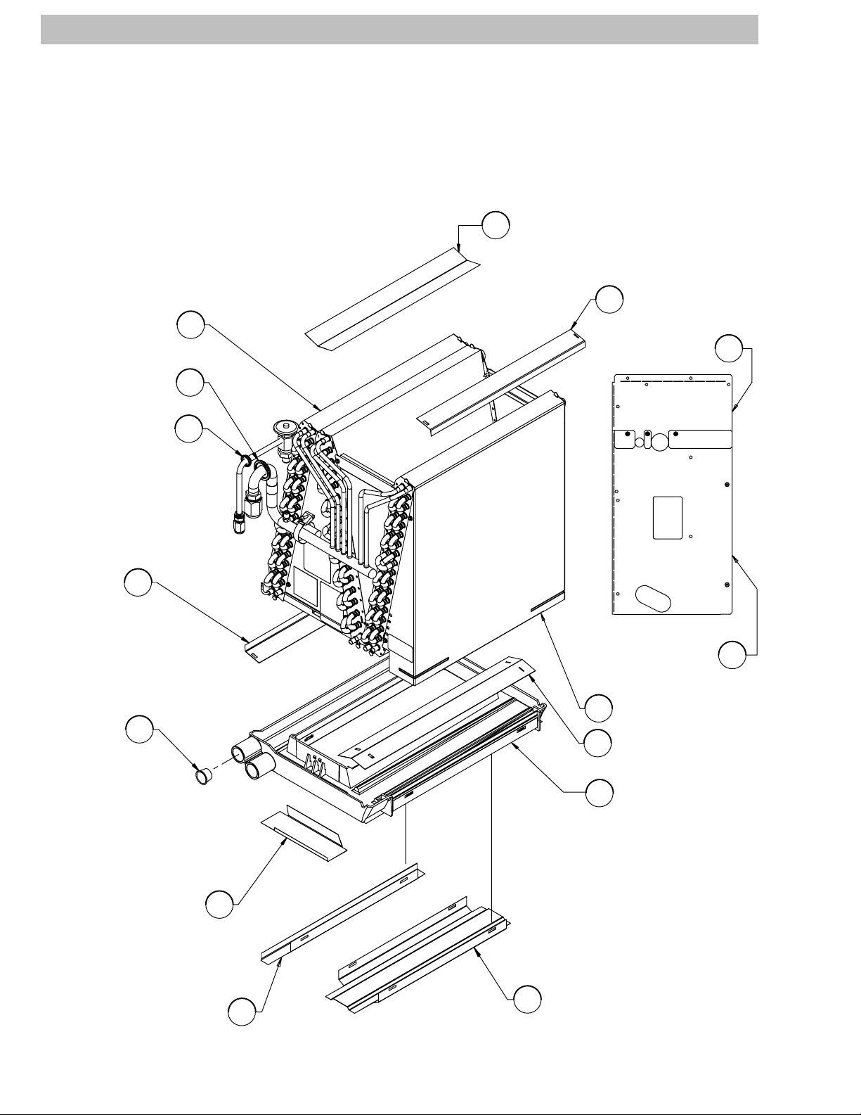
EMA
NOTE: This illustration is for
reference only. Your unit may
differ in appearance or may not
include all components shown.
Shield, Left / Center Coil
E
Shield
A
Coil Assembly
Suction Line Grommet
Liquid Line Grommet
Shield
Drain Plug
A
D
1
M
N
Panel, Front Upper
Cover Assembly
Panel, Front Lower
Enclosure, Coil
G
Shield, Right Coil
F
L
P
Pan, Condensate
7
Shield, Cond. Pan Front
Shield, Cond. Pan Left
2 484 04 5600 00
K
H
J
Shield, Cond. Pan Right
38−11 −85
TECHNICAL SUPPORT MANUAL Coils for Manufactured Housing: EMA2X, EMA4X
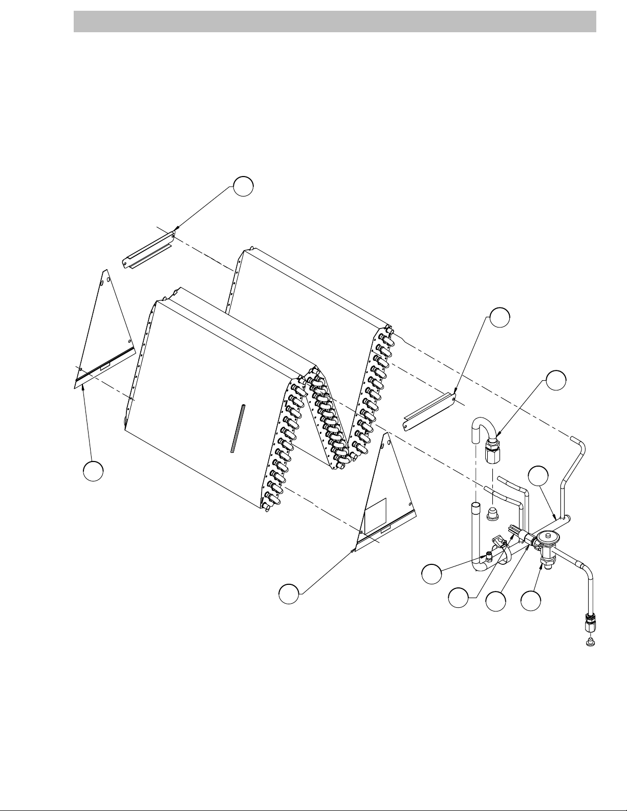
EMA
NOTE: This illustration is for
reference only. Your unit may
differ in appearance or may not
include all components shown.
Bracket, Tie
C
Bracket, Tie
C
B
Plate, Delta
B
Plate, Delta
Access
Fitting 5
Distributor
Assembly
6
Distributor
2
Coupling
Assembly
S
Suction,
Header
Assembly
2
4
TXV
38−11 −85a
484 04 5600 00 3

TECHNICAL SUPPORT MANUAL Coils for Manufactured Housing: EMA2X, EMA4X
EMA2X24DA1−EMA2X48DA1 SERIES PARTS LIST
KEY
NO.
DESCRIPTION PART NO.
EMA2X24DA1
EMA2X36DA1
1 Evap. Coil Assy (Ref. Only) 1173358 1
1 1173376 − 1
1 1173382 − − 1
2 Suction Header Asy. 1173359 1
2 1173377 − 1
2 1173383 − − 1
3 Distributor 1173360 1
3 1173093 − 1 1
4 Thermo Expansion Valve (TXV) 1173165 1 1
4 1173166 − − 1
5 Access Fitting 1171507 1 1 1
6 Distributor Assembly 1173361 1
6 1173139 − 1 1
7 Condensate Pan 1173362 1 1 1
A Shield 1173364 2 2 2
B Plate Delta (Triangle) 1173365 2
B 1173379 − 2
B 1173384 − − 2
C Tie Bracket 1173366 2
C 1173380 − 2 2
D Drain Plug 1085010 1 1 1
E Shield, Left/Center Coil 1173367 1 1 1
F Shield, Right Coil 1173368 1 1 1
G Coil Enclosure 1173369 1
G 1173381 − 1
G 1173385 − − 1
H Shield, Condensate Pan Left 1173370 1 1 1
J Shield, Condensate Pan Right 1173371 1 1 1
K Shield, Condensate Pan Front 1173372 1 1 1
L Panel, Front Upper 1173373 1 1 1
M Grommet, Suction Line 1173158 1
M 1173159 − 1
M 1173160 − − 1
N Grommet, Liquid Line 1173157 1 1 1
P Panel, Front Lower 1173374 1 1 1
)( Strainer 1171739 1 1 1
)( Drain Assy 1173375 1 1 1
)( Warranty 40106403001 1 1 1
)( Installation Instruction Manual 48401320000 1 1 1
EMA2X48DA1
4 484 04 5600 00

TECHNICAL SUPPORT MANUAL Coils for Manufactured Housing: EMA2X, EMA4X
EMA2X24DAT1−EMA2X48DAT1 SERIES PARTS LIST (Tin Coated)
KEY
NO.
DESCRIPTION PART NO.
EMA2X24DAT1
EMA2X36DAT1
1 Evap. Coil Assy (Ref. Only) 1173598 1
1 1173599 − 1
1 1173600 − − 1
2 Suction Header Asy. 1173359 1
2 1173377 − 1
2 1173383 − − 1
3 Distributor 1173360 1
3 1173093 − 1 1
4 Thermo Expansion Valve (TXV) 1173165 1 1
4 1173166 − − 1
5 Access Fitting 1171507 1 1 1
6 Distributor Assembly 1173361 1
6 1173139 − 1 1
7 Condensate Pan 1173362 1 1 1
A Shield 1173364 2 2 2
B Plate Delta (Triangle) 1173365 2
B 1173379 − 2
B 1173384 − − 2
C Tie Bracket 1173366 2
C 1173380 − 2 2
D Drain Plug 1085010 1 1 1
E Shield, Left/Center Coil 1173367 1 1 1
F Shield, Right Coil 1173368 1 1 1
G Coil Enclosure 1173369 1
G 1173381 − 1
G 1173385 − − 1
H Shield, Condensate Pan Left 1173370 1 1 1
J Shield, Condensate Pan Right 1173371 1 1 1
K Shield, Condensate Pan Front 1173372 1 1 1
L Panel, Front Upper 1173373 1 1 1
M Grommet, Suction Line 1173158 1
M 1173159 − 1
M 1173160 − − 1
N Grommet, Liquid Line 1173157 1 1 1
P Panel, Front Lower 1173374 1 1 1
)( Strainer 1171739 1 1 1
)( Drain Assy 1173375 1 1 1
)( Warranty 40106403001 1 1 1
)( Installation Instruction Manual 48401320000 1 1 1
EMA2X48DAT1
484 04 5600 00 5

TECHNICAL SUPPORT MANUAL Coils for Manufactured Housing: EMA2X, EMA4X
EMA4X24DA1−EMA4X48DA1 SERIES PARTS LIST
KEY
NO.
DESCRIPTION PART NO.
EMA4X24DA1
EMA4X36DA1
1 Evap. Coil Assy (Ref. Only) 1173386 1
1 1173388 − 1
1 1173390 − − 1
2 Suction Header Asy. 1173359 1
2 1173377 − 1
2 1173383 − − 1
3 Distributor 1173360 1
3 1173093 − 1 1
4 Thermo Expansion Valve (TXV) 1173387 1
4 1173389 − 1
4 1173391 − − 1
5 Access Fitting 1171507 1 1 1
6 Distributor Assembly 1173361 1
6 1173138 − 1
6 1173139 − − 1
7 Condensate Pan 1173362 1 1 1
A Shield 1173364 2 2 2
B Plate Delta (Triangle) 1173365 2
B 1173379 − 2
B 1173384 − − 2
C Tie Bracket 1173366 2
C 1173380 − 2 2
D Drain Plug 1085010 1 1 1
E Shield, Left/Center Coil 1173367 1 1 1
F Shield, Right Coil 1173368 1 1 1
G Coil Enclosure 1173369 1
G 1173381 − 1
G 1173385 − − 1
H Shield, Condensate Pan Left 1173370 1 1 1
J Shield, Condensate Pan Right 1173371 1 1 1
K Shield, Condensate Pan Front 1173372 1 1 1
L Panel, Front Upper 1173373 1 1 1
M Grommet, Suction Line 1173158 1
M 1173159 − 1
M 1173160 − − 1
N Grommet, Liquid Line 1173157 1 1 1
P Panel, Front Lower 1173374 1 1 1
)( Strainer 1171739 1 1 1
)( Drain Assy 1173375 1 1 1
)( Warranty 40106403001 1 1 1
)( Installation Instruction Manual 48401320000 1 1 1
EMA4X48DA1
6 484 04 5600 00

TECHNICAL SUPPORT MANUAL Coils for Manufactured Housing: EMA2X, EMA4X
EMA4X24DAT1−EMA4X48DAT1 SERIES PARTS LIST (Tin Coated)
KEY
NO.
DESCRIPTION PART NO.
EMA4X24DAT1
EMA4X36DAT1
1 Evap. Coil Assy (Ref. Only) 1173607 1
1 1173608 − 1
1 1173609 − − 1
2 Suction Header Asy. 1173359 1
2 1173377 − 1
2 1173383 − − 1
3 Distributor 1173360 1
3 1173093 − 1 1
4 Thermo Expansion Valve (TXV) 1173387 1
4 1173389 − 1
4 1173391 − − 1
5 Access Fitting 1171507 1 1 1
6 Distributor Assembly 1173361 1
6 1173138 − 1
6 1173139 − − 1
7 Condensate Pan 1173362 1 1 1
A Shield 1173364 2 2 2
B Plate Delta (Triangle) 1173365 2
B 1173379 − 2
B 1173384 − − 2
C Tie Bracket 1173366 2
C 1173380 − 2 2
D Drain Plug 1085010 1 1 1
E Shield, Left/Center Coil 1173367 1 1 1
F Shield, Right Coil 1173368 1 1 1
G Coil Enclosure 1173369 1
G 1173381 − 1
G 1173385 − − 1
H Shield, Condensate Pan Left 1173370 1 1 1
J Shield, Condensate Pan Right 1173371 1 1 1
K Shield, Condensate Pan Front 1173372 1 1 1
L Panel, Front Upper 1173373 1 1 1
M Grommet, Suction Line 1173158 1
M 1173159 − 1
M 1173160 − − 1
N Grommet, Liquid Line 1173157 1 1 1
P Panel, Front Lower 1173374 1 1 1
)( Strainer 1171739 1 1 1
)( Drain Assy 1173375 1 1 1
)( Warranty 40106403001 1 1 1
)( Installation Instruction Manual 48401320000 1 1 1
EMA4X48DAT1
484 04 5600 00 7

TECHNICAL SUPPORT MANUAL Coils for Manufactured Housing: EMA2X, EMA4X
STATIC PRESSURE DROP ACROSS COIL AT A GIVEN CFM
Static Pressure Drop Across Coil (Inches Water Column)
Coil Size CFM Across Coil
24
2 tons
36
3 tons
48
4 tons
* Excessive pressure drop, application not recommended.
700
800
900
1000
1100
1200
1300
1400
1400 0.322 0.348
1500 0.366 0.396
1600 0.413 0.446
1700 * *
1800 * *
Dry Wet
0.182 0.214
0.233 0.269
0.290 0.336
0.189 0.236
0.221 0.276
0.259 0.315
0.299 0.361
0.341 0.413
COIL MODEL NUMBER IDENTIFICATION GUIDE
E M A 2 X 24 D A 1
E = Evaporator
D = Deluxe
B = Builder
M = Manufactured Home
H = Horizontal Slab TYPE
M = Cased, Multipositon
D = Cased, Upflow / Downflow
A = Loose APPLICATION
2 = R−22
4 = Environmentally Sound R−410A REFRIGERANT
X = TXV METERING DEVICE
18 = 18,000 BTUH = 1½ tons
24 = 24,000 BTUH = 2 tons
30 = 30,000 BTUH = 2½ tons
36 = 36,000 BTUH = 3 tons
42 = 42,000 BTUH = 3½ tons
48 = 48,000 BTUH = 4 tons
60 = 60,000 BTUH = 5 tons NOMINAL CAPACITY
A = 11.8”
B = 15.5”
D = 17.9”
F = 19.1”
J = 22.8”
L = 24.5” WIDTH
A = Standard
AT = Tin Coated Copper Tubes for Additional Corrosion Protection SALES CODE / FEATURES
Engineering Revision
8 484 04 5600 00

TECHNICAL SUPPORT MANUAL Coils for Manufactured Housing: EMA2X, EMA4X
R−410A QUICK REFERENCE GUIDE
• R−410A refrigerant operates at 50% − 70% higher pressures than R−22. Be sure that servicing equipment and
replacement components are designed to operate with R−410A.
• R−410A refrigerant cylinders are rose colored.
• Recovery cylinder service pressure rating must be 400 psig, DOT 4BA400 or DOT BW400.
• R−410A systems should be charged with liquid refrigerant. Use a commercial type metering device in the
manifold hose.
• Manifold sets should be 750 psig high−side and 200 psig low−side with 520 psig low−side retard.
• Use hoses with 750 psig service pressure rating.
• Leak detectors should be designed to detect HFC refrigerant.
• R−410A, as with other HFC refrigerants, is only compatible with POE oils.
• Vacuum pumps will not remove moisture from oil.
• Do not use liquid line filter−driers with rated working pressures less than 600 psig.
• Do not install a suction line filter−drier in liquid line.
• POE oils absorb moisture rapidly. Do not expose oil to atmosphere.
• POE oils may cause damage to certain plastics and roofing materials.
• Wrap all filter−driers and service valves with wet cloth when brazing.
• A liquid line filter−drier is required on every unit.
• Do not use with an R−22 TXV.
• If indoor unit is equipped with an R−22 TXV, it must be changed to an R−410A TXV.
• Never open system to atmosphere while it is under a vacuum.
• When system must be opened for service, break vacuum with dry nitrogen and replace all filter−driers.
• Do not vent R−410A into the atmosphere.
• Do not use capillary tube indoor coils.
• Observe all WARNINGS, CAUTIONS, NOTES, and bold text.
International Comfort Products, LLC
Lewisburg, Tennessee 37091
484 04 5600 00 9
 Loading...