

International comfort products R-410A, HC4A3 Series Installation Instructions Manual
INSTALLATION INSTRUCTIONS
WARNING
R−410A Ducted Horizontal Air Conditioner
Product Family: HC4A3
Fig. 1 - HC4A3
NOTE: Read the entire instruction manual before starting
the installation.
TABLE OF CONTENTS
PAGE
SAFETY CONSIDERATIONS 1. . . . . . . . . . . . . . . . . . . . . . . .
INSTALLATION 2 − 9. . . . . . . . . . . . . . . . . . . . . . . . . . . . . . . . .
Step 1 − Complete Pre−Installation Checks 2. . . . . . . .
Step 2 − Rig and Mount Unit 2. . . . . . . . . . . . . . . . . . . . .
Step 3 − Complete Refrigerant Piping Connections 5. .
Step 4 − Make Electrical Connections 8. . . . . . . . . . . . .
START−UP 11. . . . . . . . . . . . . . . . . . . . . . . . . . . . . . . . . . . . . . .
SERVICE 11. . . . . . . . . . . . . . . . . . . . . . . . . . . . . . . . . . . . . . . .
MAINTENANCE 15. . . . . . . . . . . . . . . . . . . . . . . . . . . . . . . . . . .
TROUBLESHOOTING 15. . . . . . . . . . . . . . . . . . . . . . . . . . . . .
SAFETY CONSIDERATIONS
Improper installation, adjustment, alteration, service,
maintenance, or use can cause explosion, fire, electrical
shock, or other conditions which may cause death, personal
injury, or property damage. Consult a qualified installer,
service agency, or your distributor or branch for information
or assistance. The qualified installer or agency must use
factory−authorized kits or accessories when modifying this
product. Refer to the individual instructions packaged with
the kits or accessories when installing.
Follow all safety codes. Wear safety glasses, protective
clothing, and work gloves. Use quenching cloth for brazing
operations. Have fire extinguisher available. Read these
instructions thoroughly and follow all warnings or cautions
included in literature and attached to the unit. Consult local
building codes and National Electrical Code (NEC) for
special requirements.
Recognize safety information. This is the safety−alert
symbol
instructions or manuals, be alert to the potential for personal
injury. Understand these signal words; DANGER,
WARNING, and CAUTION. These words are used with the
safety−alert symbol. DANGER identifies the most serious
hazards which will result in severe personal injury or death.
WARNING signifies hazards which could result in personal
injury or death. CAUTION is used to identify unsafe
practices which would result in minor personal injury or
product and property damage. NOTE is used to highlight
suggestions which will result in enhanced installation,
reliability, or operation.
!
!
When you see this symbol on the unit and in
!
ELECTRICAL SHOCK HAZARD
Failure to follow this warning could result in
personal injury or death.
Before installing, modifying, or servicing system,
main electrical disconnect switch must be in the
OFF position. There may be more than 1
disconnect switch. Lock out and tag switch with a
suitable warning label.
421 01 9701 00 May 2009
INSTALLATION
!
UNIT OPERATION AND SAFETY HAZARD
Failure to follow this warning could result in personal
injury or equipment damage.
R−410A refrigerant systems operate at higher
pressures than standard R−22 systems. Do not use
R−22 service equipment or components on R−410A
refrigerant equipment.
PERSONAL INJURY AND EQUIPMENT DAMAGE
HAZARD
Failure to follow this caution may result in personal
injury and / or equipment damage.
DO NOT operate the unit without a filter or with grille
removed.
Step 1 —Complete Pre−Installation Checks
Unpack Unit
Move the unit to final location. Remove unit from carton,
being careful not to damage service valves and grilles.
Inspect Shipment
File a claim with the shipping company if shipment is
damaged or incomplete. Check the unit nameplates to
ensure units match job requirements.
WARNING
!
CAUTION
Consider System Requirements
Consult local building codes and NEC for special installation
requirements.
Allow sufficient space for airflow clearance, wiring,
refrigerant piping, and servicing unit. See Fig. 2.
Locate unit so that condenser airflow is unrestricted on both
sides. Refer to Fig. 2.
Unit may be mounted on a level pad directly on base legs or
mounted on raised pads at support points. See Fig. 2 for
center of gravity.
Matching the Condensing Unit to an Indoor Unit
The HC4A318−60 ducted condensing units can be matched
to corresponding indoor units. The HC4A3 unit can be
matched with under−ceiling and residential fan coils and
evaporator coils. Refer to separate indoor unit literature for
more information.
Step 2 —RIG AND MOUNT UNIT
Mounting on Ground
Mount unit on a solid, level concrete pad. Position unit so
water or ice from roof does not fall directly onto unit.
Accessory stacking kits can be used when units are to be
stacked. See installation instructions provided with the
accessory kit. Use field−provided snow stand or ice rack
where prolonged subfreezing temperatures or heavy snow
occurs.
If conditions or local codes require unit be fastened to a pad,
6 field−supplied tiedown bolts should be used and fastened
through slots provided in unit mounting feet.
Mounting on Roof
Mount unit on a level platform or frame at least 6 in. (152.4
mm) above roof surface. Isolate unit and tubing from
structure.
2 421 01 9701 00

1
SHIPPING
DIMENSIONS (L x W x H)
FIELD POWER SUPPLY CONN.
HOLE SIZES PROVIDED:
7/8−1/2TRADE
1 3/16−3/4TRADE
1 3/8−1TRADE
SHIPPING
WEIGHT(lbs)
WEIGHT(lbs)
OPERATING
1. REQUIRED CLEARANCES: WITH COIL FACING WALL; ALLOW 6 MIN
CLEARANCE ON COIL SIDE AND COIL END AND 36 MIN CLEARANCE
ON COMPRESSOR END AND FAN SIDE. WITH FAN FACING WALL; ALLOW 8 MIN
CLEARANCE ON FAN SIDE AND COIL END AND 36 MIN CLEARANCE
ON COMPRESSOR END AND COIL SIDE. WITH MULTI UNIT APPLICATION;
ARRANGE UNITS SO DISCHARGE OF ONE DOES NOT ENTER INLET OF ANOTHER.
2. MINIMUM OUTDOOR OPERATING AMBIENT IN COOLING
MODE IS 55 $F, MAX. 125 $F.
3. SERIES DESIGNATION IS THE 10TH POSITION OF THE
UNIT MODEL NUMBER.
4. CENTER OF GRAVITY
5. ALL DIMENSIONS ARE IN INCHES UNLESS NOTED.
2 1/2
4 3/16
1 7/16
JUNCTION BOX FOR
POWER SUPLLY AND
CONTROL CONNECTIONS
1 1/2
FIELD CONTROL SUPPLY
WIRE ENTRY
7/8 HOLE W/GROMMET
H
G
L
VAPOR LINE CONN.
M
FEMALE SWEAT CONN.
8
3/8 LIQUID LINE
MEASUREMENT− ENGLISH
4 1/2
1
FEMALE SWEAT CONN.
P
N
AIR
ABC DE FG H J K L MNP
1/8 36 15/16 14 9/16 16 23 7/16 17 3/16 17 1/8 22 13 6 5/8 11 1/4 5/8 2 15/16 6 155 171 42 9/10 X 18 X 28 1/10
3/16 44 9/16 17 1/16 18 7/16 30 1/2 19 5/8 35 3/16 40 1/16 14 1/2 8 1/2 18 7/8 7/8 3 7/16 6 1/2 284 309 50 1/2 X 20 1/2 X 46 2/
3/16 44 9/16 17 1/16 18 7/16 30 1/2 19 5/8 29 3/16 34 1/16 13 11/16 8 1/8 15 7/8 3/4 3 7/16 6 1/2 200 223 50 1/2 X 20 1/2 X 40 2/
X = YES
O = NO
E
460−3−60
208/230−3−60
ELECTRICAL
CHARACTERISTICS
UNIT SERIES
HC4A324**A 1,2 XOOO311/8 36 15/16 14 9/16 16 23 7/16 17 3/16 23 1/8 28 14 6 3/4 11 5/8 5/8 2 15/16 6 180 198 42 9/10 X 18 X 34 1/10
HC4A330**A 1 XOOO37
HC4A336**A 1 XOXX373/16 44 9/16 17 1/16 18 7/16 30 1/2 19 5/8 29 3/16 34 1/16 13 11/16 8 1/8 15 7/8 3/4 3 7/16 6 1/2 218 240 50 1/2 X 20 1/2 X 40 2/1HC4A348**A 1,2 XOXX43
HC4A318**A 1 XOOO25
HC4A360**A 1,2 XOXX433/16 44 9/16 17 1/16 18 7/16 30 1/2 19 5/8 35 3/16 40 1/16 14 1/2 8 1/2 18 7/8 7/8 3 7/16 6 1/2 294 319 50 1/2 X 20 1/2 X 46 2/
230−1−60
208−230−1−60
421 01 9701 00 3
K
J
7 1/2
AIR
11/16
FDC
Fig. 2 - HC4A3 Unit Dimensions
B
A
MINIMUM
DIMENSIONS
MOUNTING PAD
18,24 23 X 42
UNIT SIZE
30,36,48,60 24 X 50
3
SHIPPING
DIMENSIONS (L x W x H)
FIELD POWER SUPPLY CONN.
HOLE SIZES PROVIDED:
22.22 − 12.70 TRADE
30.16 − 19.05 TRADE
34.92 − 25.40 TRADE
SHIPPING
WEIGHT(KG)
WEIGHT(KG)
OPERATING
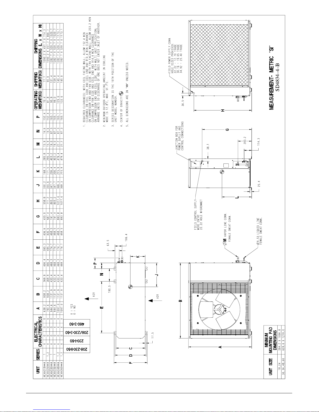
1. REQUIRED CLEARANCES: WITH COIL FACING WALL; ALLOW 152.4 MIN
CLEARANCE ON COIL SIDE AND COIL END AND 914.4 MIN CLEARANCE
ON COMPRESSOR END AND FAN SIDE. WITH FAN FACING WALL; ALLOW 203.2 MIN
CLEARANCE ON FAN SIDE AND COIL END AND 914.4 MIN CLEARANCE
ON COMPRESSOR END AND COIL SIDE. WITH MULTI UNIT APPLICATION;
ARRANGE UNITS SO DISCHARGE OF ONE DOES NOT ENTER INLET OF ANOTHER.
2. MINIMUM OUTDOOR OPERATING AMBIENT IN COOLING
MODE IS 12.8 $C, MAX. 51.7 $C.
3. SERIES DESIGNATION IS THE 10TH POSITION OF THE
UNIT MODEL NUMBER.
4. CENTER OF GRAVITY
5. ALL DIMENSIONS ARE IN MM UNLESS NOTED.
JUNCTION BOX FOR
POWER SUPLLY AND
63.5
106.4
K
P
36.5
CONTROL CONNECTIONS
FIELD CONTROL SUPPLY
WIRE ENTRY
22.22 HOLE W/GROMMET
38.1
H
G
L
VAPOR LINE CONN.
M
FEMALE SWEAT CONN.
203.2
MEASUREMENT− METRIC SI
114.3
25.4
9.53 LIQUID LINE
FEMALE SWEAT CONN.
N
N
AIR
ABCD EFGH JKLM NP
X = YES
O = NO
E
460−3−60
208/230−3−60
ELECTRICAL
CHARACTERISTICS
UNIT SERIES
HC4A318**A 1 XOOO 638.2 938.2 369.9 406.4 595.3 436.6 435.0 558.8 330.2 168.3 285.8 15.9 74.6 152.4 70.4 77.7 1090.2 X 457.7 X 714.
HC4A324**A 1,2 XOOO 790.6 938.2 369.9 406.4 595.3 436.6 587.4 711.2 355.6 171.5 295.3 15.9 74.6 152.4 81.8 90.0 1090.2 X 457.7 X 866.
HC4A330**A 1 XOOO 944.6 1131.9 433.4 468.3 774.7 498.5 741.4 865.2 347.7 206.4 403.2 19.0 87.3 165.1 90.9 101.4 1282.7 X 520.7 X 1020.
HC4A336**A 1 XOXX 944.6 1131.9 433.4 468.3 774.7 498.5 741.4 865.2 347.7 206.4 403.2 19.0 87.3 165.1 99.0 109.0 1282.7 X 520.7 X 1020.
HC4A348**A 1,2 XOXX 1097.0 1131.9 433.4 468.3 774.7 498.5 893.8 1017.6 368.3 215.9 479.4 22.2 87.3 165.1 129.0 140.4 1282.7 X 520.7 X 1173.1
HC4A360**A 1,2 XOXX 1097.0 1131.9 433.4 468.3 774.7 498.5 893.8 1017.6 368.3 215.9 479.4 22.2 87.3 165.1 133.6 145.0 1282.7 X 520.7 X 1173.1
230−1−60
208−230−1−60
4 421 01 9701 00
J
190.5
AIR
17.5
FDC
Fig. 3 - HC4A3 Unit Dimensions
B
A
MINIMUM
DIMENSIONS
MOUNTING PAD
18,24 584.2 X 1066.8
UNIT SIZE
30,36,48,60 609.6 X 1270.0
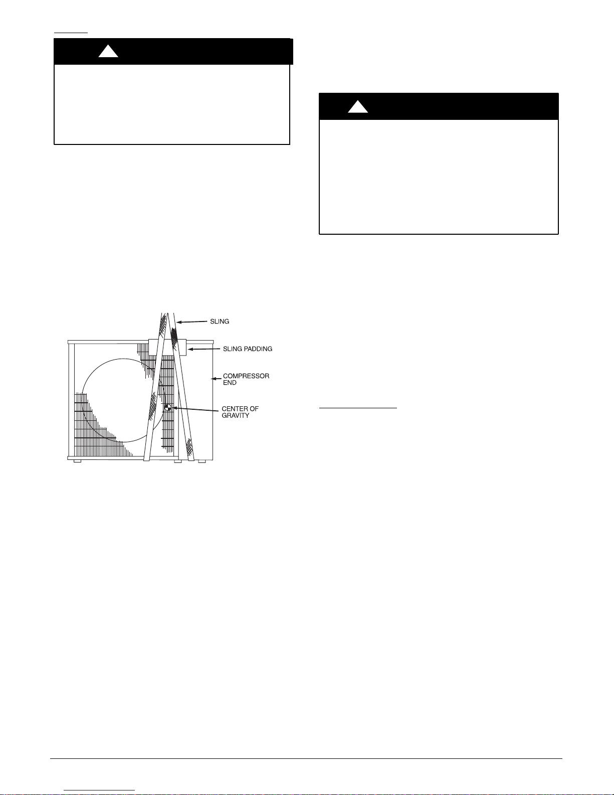
Rigging
!
CAUTION
PERSONAL INJURY AND/OR EQUIPMENT
DAMAGE HAZARD
Failure to follow this caution may result in personal
injury and/or equipment damage.
Be sure unit panels are securely in place prior to
rigging.
Keep the unit upright and lift unit using a sling. Use
cardboard or padding under the sling, and spreader bars to
prevent sling damage to the unit. See Fig. 4. See Fig. 2 for
center of gravity reference. Install the unit so that the coil
does not face into prevailing winds. If this is not possible
and constant winds above 25 mph are expected, use
accessory wind baffle. See installation instructions provided
with the accessory kit.
NOTE: Accessory wind baffles should be used on all units
with accessory low ambient temperature control.
Field−fabricated snow or ice stands may be used to raise
unit when operation will be required during winter months.
Units may also be wall mounted using the accessory wall
mounting kit.
A07396
Fig. 4 - Lifting Unit with Sling
Step 3 —COMPLETE REFRIGERANT PIPING
CONNECTIONS
Outdoor units may be connected to indoor units using
field−supplied tubing of refrigerant grade and condition. See
Table 1 for correct line sizes. Do not use less than 10 ft
(3.05 m) of interconnecting tubing.
!
UNIT DAMAGE HAZARD
Failure to follow this caution may result in equipment
damage or improper operation.
If any section of pipe is buried, there must be a 6 in.
(152.4 mm) vertical rise to the valve connections on
the outdoor unit. If more than the recommended
length is buried, refrigerant may migrate to cooler,
buried section during extended periods of system
shutdown. This causes refrigerant slugging and
could possibly damage the compressor at start−up.
When more than 80 ft (24.38 m) of interconnecting tubing
and more than 20 ft (6.10 m) of vertical lift is used, consult
the residential Long Line Application Guide for required
accessories. If either refrigerant tubing or indoor coil is
exposed to the atmosphere, the system must be evacuated
following good refrigeration practices.
Run refrigerant tubes as directly as possible, avoiding
unnecessary turns and bends. Suspend refrigerant tubes so
they do not damage insulation on vapor tube and do not
transmit vibration to structure. Also, when passing
refrigerant tubes through a wall, seal the opening so that
vibration is not transmitted to structure. Leave some slack in
refrigerant tubes between structure and outdoor unit to
absorb vibration. Refer to separate indoor unit installation
instructions for additional information.
Expansion Device
A hard shutoff, thermostatic expansion valve (TXV) is
required at the indoor section of the system for proper
operation of these products. If the indoor section of the
system is not equipped with a hard shutoff TXV, refer to
Spec Sheet for the correct TXV kit to be installed. Follow
the instructions in the kit for proper installation.
CAUTION
421 01 9701 00 5
 Loading...