

International comfort products C9MPV050F12D1, C9MPT050F12C1, H9MPT050F12C1, T9MPT050F12C1, C9MPT075F14C1 Technical Support Manual
...
Four Position Furnace
Models
Dual Certified
*9MPT050F12C1
*9MPT075F14C1
*9MPT100J16C1
*9MPT125L20C1
*9MPV050F12D1
*9MPV075F12D1
*9MPV100J20D1
*9MPV125L20D1
*9MVX040F12A1
*9MVX060F12A1
*9MVX080J20A1
*9MVX100L20A1
Technical Support (*9MPT) 2................
Circulation Air Blower Data (*9MPT) 3.........
Wiring Diagram (*9MPT) 4..................
Parts (*9MPT) 5..........................
Technical Support (*9MPV) 8...............
Circulation Air Blower Data (*9MPV) 9.........
Exploded Parts View (*9MPV & *9MVX) 17......
Parts (*9MPV) 19..........................
Technical Support (*9MVX) 20...............
Circulation Air Blower Data (*9MVX) 21.........
Parts (*9MVX) 30..........................
Wiring Diagram (*9MPV & *9MVX) 32...........
Save This Manual For Future Reference
440 04 2024 01 Feb. 2009
* Denotes Brand (C, H, T)
International Comfort Products, LLC
Lewisburg, TN 37091 U.S.A.
1
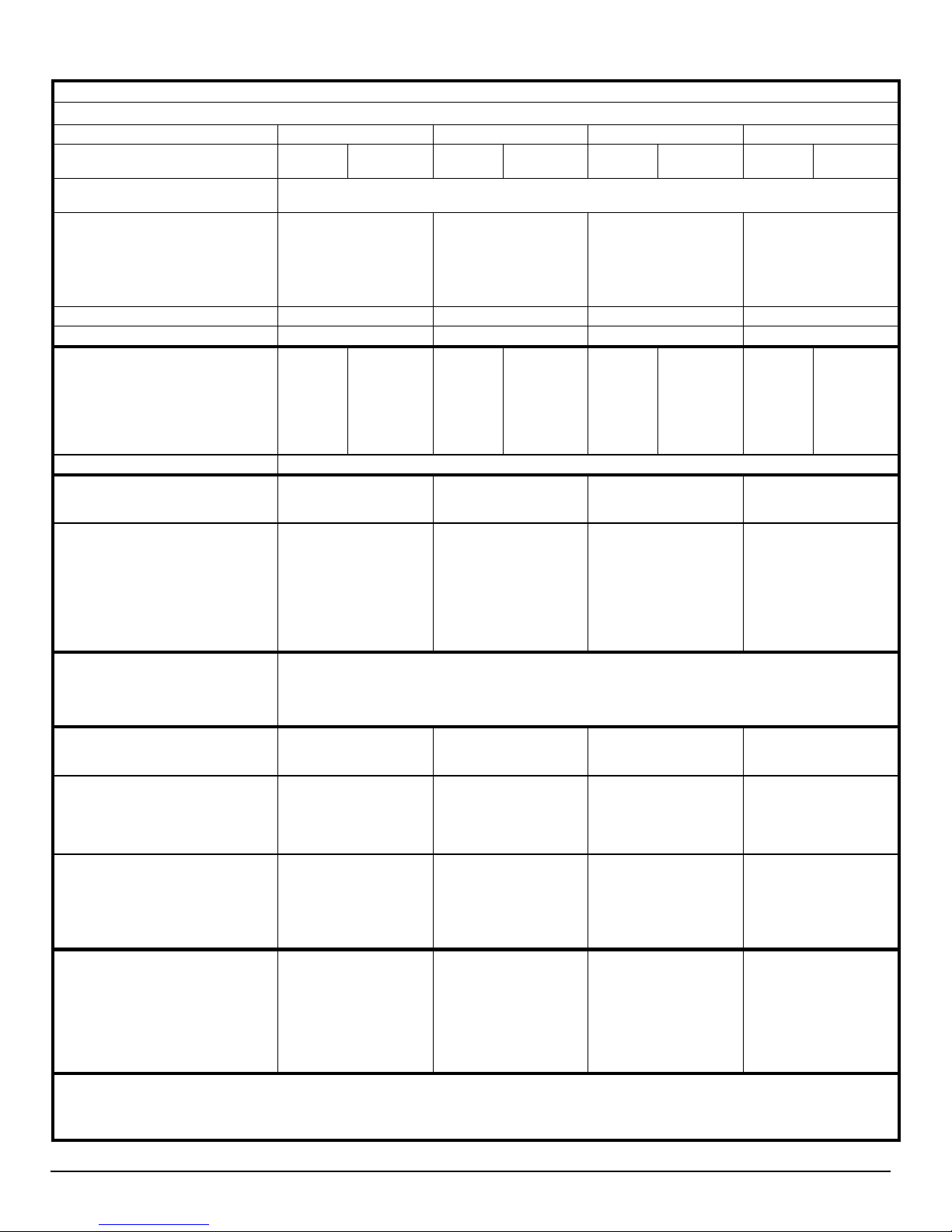
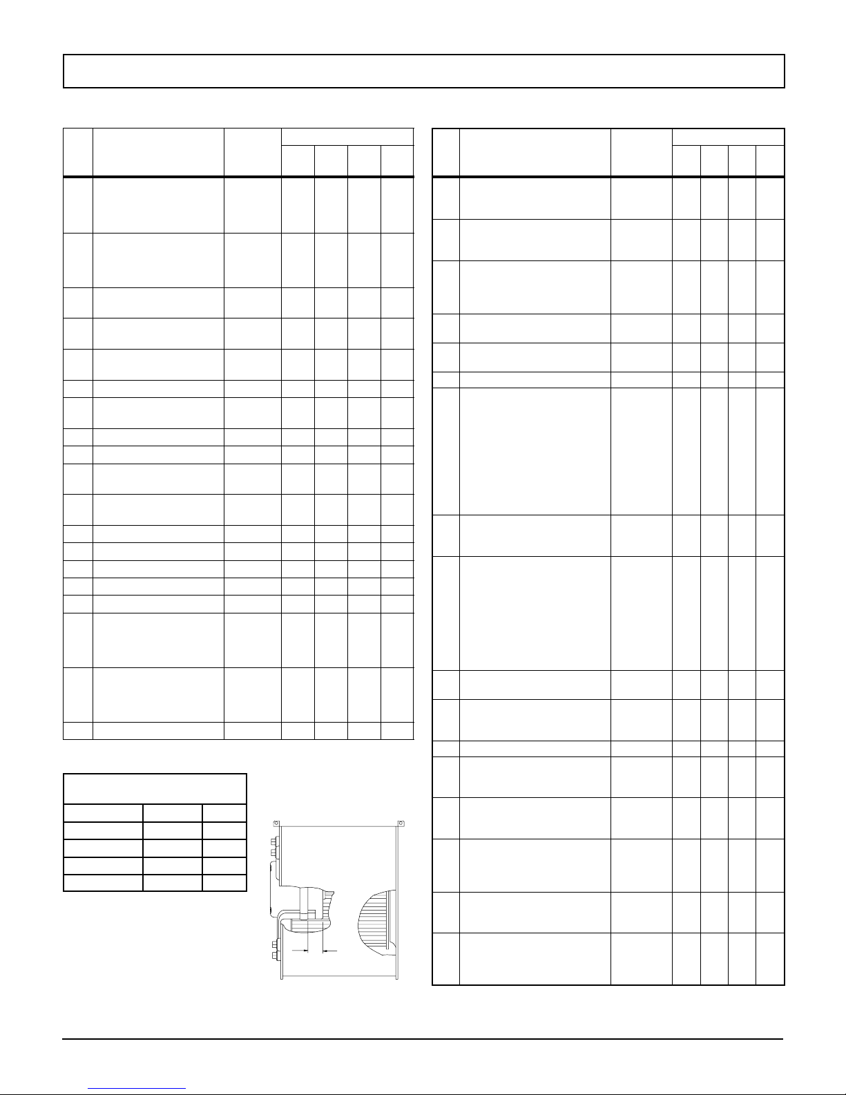
TECHNICAL SUPPORT
Manufacturers Number (Mfr No --SeeRatingPlate) ALL Models
Specifications
*9MPT050F12 *9MPT075F14 *9MPT100J16 *9MPT125L20
General
Gas Type
Transformer Size (VA)
T’stat Heat Anticipator
Input (Btuh) Std/Alt. HI Heat
LO Heat
Output (Btuh) Std/Alt. HI Heat
Tem p. Ri s e (
oF/o
LO Heat
C) HI Heat
LO Heat
Electrical (Volts/Hz) 115/60 115/60 115/60 115/60
Rating Plate Amps 11. 8 11. 8 11. 8 14.0
Gas & Ignition
Gas Type
Std. Main Orifices (No/Size)
Gas Valve (Honeywell)
Regulation Type
Manifold Press. HI Heat (in wc/Pa)
LO Heat (in wc/Pa)
Ignition Type/Series Hot Surface
Combustion
Flue Outlet Size (Inches)
Std. Outlet Temp (
oF/o
C)
@Blower/ @ Transition Box (HI Heat)
Std. Pressures (in wc/Pa)
5′ No Elbows
40′ +5--90° DWV Elbows
@Blower/ @ Transition Box (LO Heat)
Std. Pressures (in wc/Pa)
5′ No Elbows
40′ +5--90° DWV Elbows
Furnace Controls
Furnace Control (Type)
Furnace Control On
(Timed--secs) Off
Limits & Controls
Rollout Switch (
Limit Control Setting (
oF/o
C)
oF/o
C)
Std. Pressure Sw. (in wc/Pa) Part No
Blower Switch Pressure (Close)
Blower Switch Pressure (Open)
Transition Switch Pressure (Close)
Transition Switch Pressure (Open)
High Alt. Pressure Sw. (in wc/Pa)
Part No
Blower Switch Pressure (Close)
Blower Switch Pressure (Open)
Transition Switch Pressure (Close)
Transition Switch Pressure (Open)
Blower Data
Blower Size -- D x W inches(mm)
Motor Amps/RPM
Motor Type/H.P.
Cap. Mfd/Volts
Filter Type & Size (qty.) in(mm)
Cool Cap. (Tons) @ .5 in wc (125 Pa)
L, ML, MHi & HI
Gas Conversion Kits All Models
Nat to Propane NAHA002LP (1172959*)
Propane to Nat NAHA002NG (1172961*)
*Order from Service Parts
Nat Propane Nat Propane Nat Propane Nat Propane
40
.50
50,000
35,000
46,000
32,000
35--65/19--46
25--55/14--30
Nat.
2/42
VR8205Q
SNAP
3.5/872
1.7/423
Propane
2/54
VR8205Q
SNAP
10.0/2490
4.9/1221
2
<140/60
--1.80/--2.60(--448/--647)
--1.30/--2.30(--324/--573)
--1.20/--1.90(--299/--473)
--1.00/--1.80(--249/--448)
VR8205Q
3.5/872
1.7/423
--1.80/--2.60(--448/--647)
--1.30/--2.30(--324/--573)
--1.20/--1.90(--299/--473)
--1.00/--1.80(--249/--448)
Nat.
3/42
SNAP
75,000
53,000
70,000
49,000
40--70/22--38
30--60/17--33
Propane
VR8205Q
10.0/2490
4.9/1221
2
<140/60
3/54
SNAP
100,000
70,000
93,000
65,000
40--70/22--38
30--60/17--33
Nat.
4/42
VR8205Q
SNAP
3.5/872
1.7/423
Propane
4/54
VR8205Q
SNAP
10.0/2490
4.9/1221
3
<140/60
--1.80/--2.60(--448/--647)
--1.70/--2.50(--423/--623)
--1.20/--1.90(--299/--473)
--1.00/--1.80(--249/--448)
125,000
87,500
117,000
82,000
40--70/22--38
30--60/17--33
Nat.
5/42
VR8205Q
SNAP
3.5/872
1.7/423
3
<140/60
--1.80/--2.60(--448/--647)
--1.70/--2.50(--423/--623)
--1.30/--2.30(--324/--573)
--1.20/--2.20(--299/--548)
Integrated
30 HI /45 LO
60,100,140,180
300/149
260/127
1013515
0.95(237)
0.80(199)
1.70(423)
1.50(374)
1013165
0.70(174)
0.55(137)
1.40(349)
1.20(299)
11 x 8(279 x 203)
10/1050
1
/
PSC/
2
10/370
16x25x1
1.5 thru 3
300/149
210/99
1013515
0.95(237)
0.80(199)
1.70(423)
1.50(374)
1013165
0.70(174)
0.55(137)
1.40(349)
1.20(299)
11 x 10(279 x 254)
10/1050
1
/
PSC/
2
10/370
16x25x1
1.5 thru 3.5
300/149
240/116
1013515
0.95(237)
0.80(199)
1.70(423)
1.50(374)
1013165
0.70(174)
0.55(137)
1.40(349)
1.20(299)
11 x 10(279 x 254)
10/1050
1
/
PSC/
2
10/370
16x25x1
2.5 thru 4
300/149
180/82
1013166
1.30(324)
1.10(274)
1.80(448)
1.60(398)
1013157
0.85(212)
0.70(174)
1.70(423)
1.50(374)
11 x 10(279 x 254)
13/900
PSC/
40/370
16x25x1 (2)
3.5 thru 5
Propane
5/54
VR8205Q
SNAP
10.0/2490
4.9/1221
3
/
4
2
Specifications are subject to change without notice.
440 04 2024 01
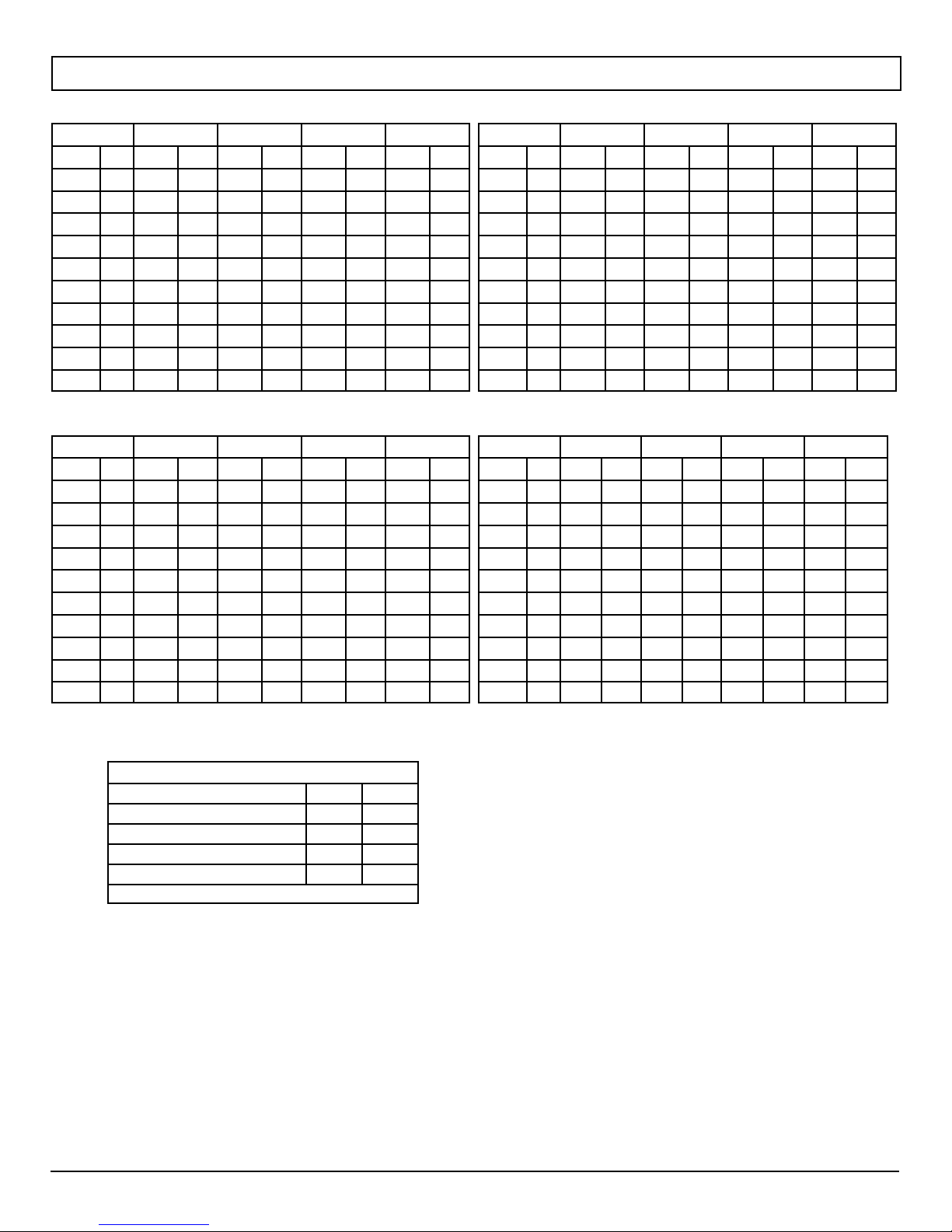
Circulation Air Blower Data - *9MPT
*9MPT050F12 (1) * Denotes Brand
Speed Tap
in wc Pa CFM L/s CFM L/s CFM L/s CFM L/s
0.1 25 826 389 1083 511 1301 614 1408 667
0.2 50 804 379 1050 495 1242 586 1347 638
0.3 75 770 363 1028 485 1195 564 1295 611
0.4 100 735 346 985 465 1153 544 1237 583
0.5 125 698 329 952 499 1093 516 1183 558
0.6 150 657 310 909 429 1040 491 111 8 528
0.7 175 -- -- -- -- -- -- 863 407 935 441 1053 497
0.8 200 -- -- -- -- -- -- 812 383 865 408 976 461
0.9 225 -- -- -- -- -- -- -- -- -- -- -- -- 802 378 887 419
1.0 250 -- -- -- -- -- -- -- -- -- -- -- -- 720 340 787 371
Low Med L Med H Hi
*9MPT100J16 (1) * Denotes Brand
Speed Tap
in wc Pa CFM L/s CFM L/s CFM L/s CFM L/s
0.1 25 823 388 1109 523 1527 721 1850 873
0.2 50 795 375 1087 513 1482 699 1791 845
0.3 75 747 353 1056 498 1426 673 1720 812
0.4 100 677 319 1016 479 1382 652 1648 778
0.5 125 617 591 970 458 1317 622 1575 743
0.6 150 544 257 857 403 1245 588 1485 701
0.7 175 -- -- -- -- -- -- 763 360 1154 545 1401 661
0.8 200 -- -- -- -- -- -- 652 308 1043 492 1284 606
0.9 225 -- -- -- -- -- -- -- -- -- -- -- -- 905 427 1161 548
1.0 250 -- -- -- -- -- -- -- -- -- -- -- -- 737 348 1028 485
Low Med L Med H Hi
*9MPT075F14 (1) * Denotes Brand *9MPT125L20 (2) * Denotes Brand
Speed Tap
in wc Pa CFM L/s CFM L/s CFM L/s CFM L/s
0.1 25 395 328 1025 484 1455 687 1724 814
0.2 50 374 318 1001 472 1410 655 1662 784
0.3 75 653 308 951 449 1365 644 1601 756
0.4 100 631 298 921 435 1309 3118 1530 722
0.5 125 609 287 891 420 1252 591 1460 689
0.6 150 569 268 845 399 1187 560 1380 651
0.7 175 529 250 799 377 1122 529 1300 613
0.8 200 490 231 730 345 1030 486 1190 562
0.9 225 -- -- -- -- -- -- 680 321 950 448 1080 510
1.0 250 -- -- -- -- -- -- -- -- -- -- -- -- 831 392 969 457
Low Med L Med H Hi
Speed Tap Low Med L Med H Hi
in wc Pa CFM L/s CFM L/s CFM L/s CFM L/s
0.1 25 1720 812 1910 901 2127 1004 2315 1092
0.2 50 1686 796 1881 888 2087 985 2268 1070
0.3 75 1644 776 1833 912 2024 955 2201 1039
0.4 100 1600 755 1777 839 1961 925 2131 1006
0.5 125 1533 723 1720 812 1891 892 2029 958
0.6 150 1494 705 1647 777 1804 851 1948 919
0.7 175 1413 667 1571 741 1708 806 1820 859
0.8 200 1306 616 1470 694 1604 757 1730 816
0.9 225 -- -- -- -- -- -- 1349 637 1484 700 1614 762
1.0 250 -- -- -- -- -- -- -- -- -- -- -- -- 1328 627 1430 675
NOTE: (1) Data based on Bottom Only or One Side return.
(2) Data based on Both Sides or Bottom plus One Side
MAX CFM (L/s) for Factory Washable Filters
Filter Size (in/mm) CFM L/s
14″ X25″ (356 x 635) 1400 661
16″ X25″ (406 x 635) 1600 755
20″ X25″ (508 x 635) 2000 944
24″ X25″ (610 x 635) 2500 1180
Max CFM (L/s) based on 600 FPM (3.0 m/s)
NOTE: Disposable filters are typically rated at 300 FPM (1.5 m/s). These filters
only allow half the airflow when compared to 600 FPM (3.0 m/s) filters.
# CFM -- Cubic feet per minute airflow (L/s -- Liters per second) Filter
required for each return--air inlet. Airflow performance includes 1″ (25.4mm)
washable 600 FPM (283 m/s) max filter media.
440 04 2024 01
Specifications are subject to change without notice.
3
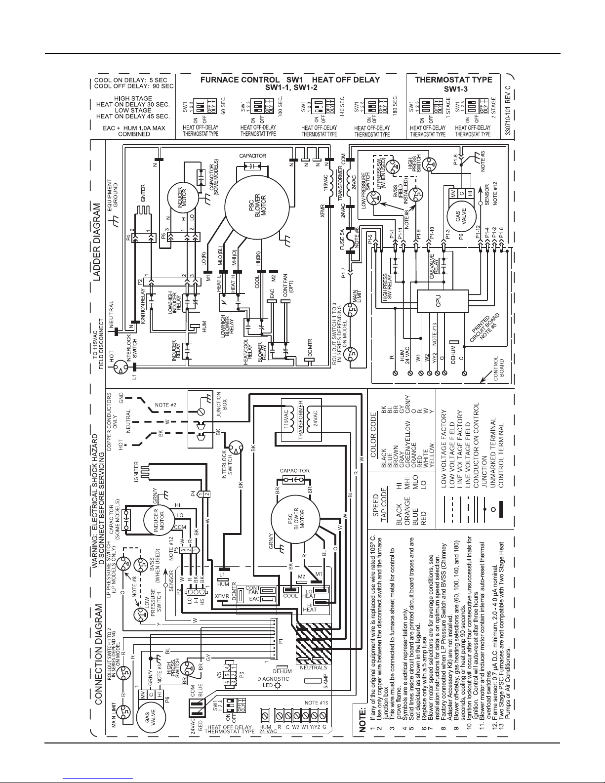
Wiring Diagram *9MPT (Two Stage Heating with PSC Motor)
4
Specifications are subject to change without notice.
440 04 2024 01
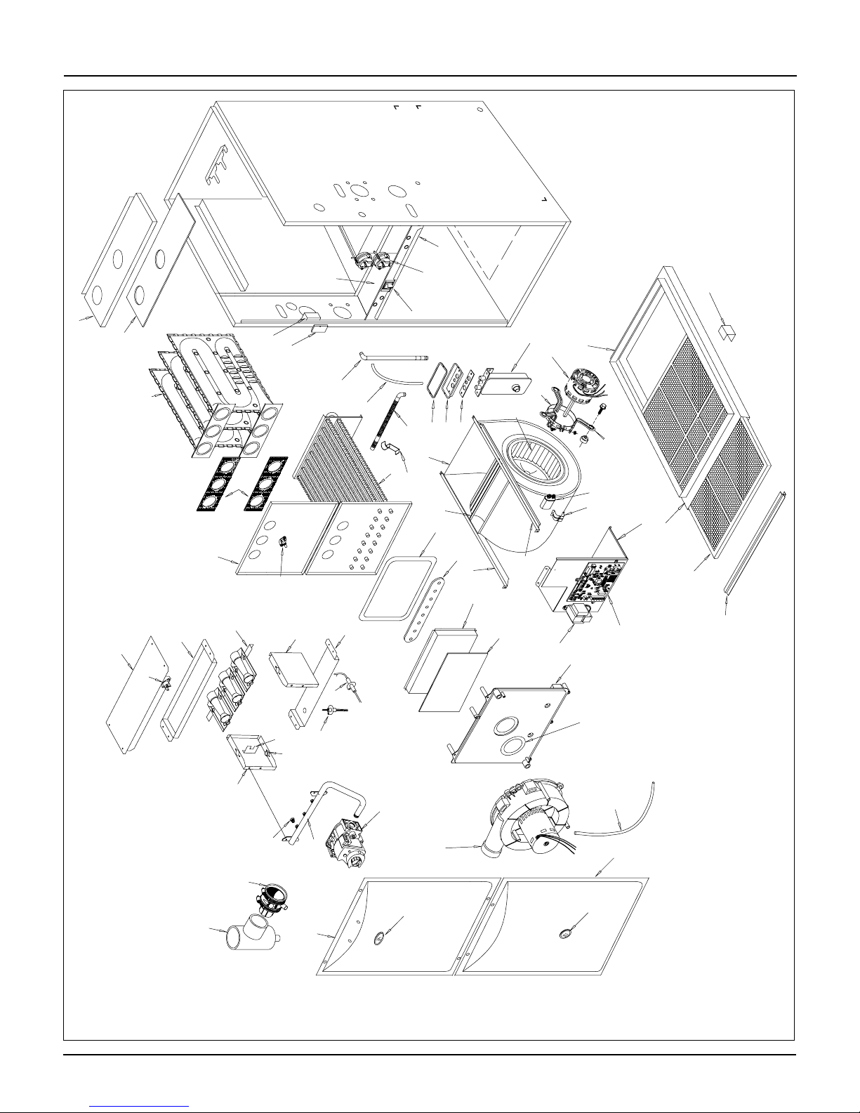
*9MPT Parts
25--24- -75a--4
M
TT
9
10
SSHRR
QQ
PP
KK
MM
3
4
5
F
A
B
1
Y
X
UU
VV
2
W
V
18
XX
7
J
U
T
K
K
D
HH
NN
20
S
OO
EE
DD
17
FF
CC
R
8
6
P
16
13
Q
14
GG
16
FF
Representative drawing only, some models may vary in appearance.
15
WW
YY
12
BB
N
O
F
F
O
11
LL
N
Specifications are subject to change without notice.
JJ
L
ZZ
5440 04 2024 01
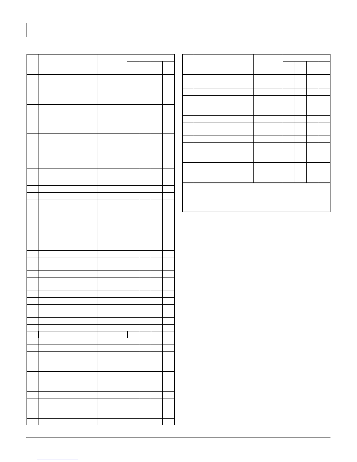
Replacement Parts - *9MPT
Models -- *9MPT050F12C1, *9MPT075F14C1, *9MPT100J16C1 & *9MPT125L20C1 (Natural Gas)
Replacement part supplied will be current active part. For parts not listed, consult place of purchase.
Key
No.
1 Heat Exchanger, Primary 1012850
2 Heat Exchanger, Secondary 1013762
3 Motor, Blower 1/1151/2CCW
4
5 Wheel, Blower 1013011
6 Transformer 1172810 1 1 1 1
7 Capacitor, 10Mfd., 370V
8 Control 1175594 1 1 1 1
9 Switch, Interlock 1171981 1 1 1 1
10 Switch, Pressure 1013166
11 Blower, Exhaust 1172826
12 Valve, Gas Nat. 2 Stage 1172822 1 1 1 1
13 Flame Sensor 1172827 1 1 1 1
14 Igniter 1172533 1 1 1 1
15 Orifice, Burner #42 Nat. 1011351 2 3 4 5
16 Switch, Limit (Rollout) 1013102 2 2 2 2
17 Burner Assembly 1172884
18 Switch, Limit (Main) 1320366
20 Filter,HH 16X25X1/2” 1010365 1 1 2 2
*See Table below for bellyband location on motor
Model *9MPT inches mm
050F12 2.09 53.1
075F14 1.81 46
100J16 1.81 46
125L20 1.65 41.9
Description
Functional
3
/4CCW
1/115
Mount, Motor kit*
40Mfd., 370V
Bellyband Location
on Motor -- A Dimensions
Part
Number
1012854
1012858
1012862
1013763
1013765
1013767
1172488
11724891--
1014824
10148231--
10114201--
1171929
11719821--
1013515--1--1
11728251--
1172965
1172966
1172967
34335002
1008445
34335001
050
F12
*9MPT
075
100
F14
J16
1
--
--
--
--
1
--
--
--
1
--
--
--
1
--
--
--
A
--
1
--
--
1
--
--
--
--
1
--
--
1
--
--
1
1
--
--
--
--
1
1
--
--
1
1
1
1
--
--
-1
1
1
--
--
--
--
1
--
-- --
1
-- --
--
--
--
--
1
--
--
1
--
125
L20
Key
No.
--
--
-1
--
--
-1
-1
-1
-1
-1
1
--
-1
--
--
-1
--
-1
--
A Panel, Top 1012866
B Gasket, Top Panel 1012603
F Partition, Blower 1172008
H Housing, Blower 1172885
J Panel, Blower Cutoff 721020013
K Hanger, Blower 1012328 2 2 2 2
L Door, Blower (Comfortmaker only)
M Bracket Asy., Door Filler 1172232
N Door, Front (Comfortmaker only)
O Clamp, Capacitor 1170643
P Transition Assembly 1172228
Q Gasket, Blower 1014425 1 1 1 1
R Board, Insulating 1012418
S Box, Collector 1012244
T Gasket, Transition 1013263
U Gasket, Collector Box 1012594
V Partition, Front Heat Exchanger 1012650
Description
Non- Functional
(Comfortmaker only)
(Comfortmaker only)
(Heil only)
(Heil only)
(Heil only)
(Tempstar only)
(Tempstar only)
(Tempstar only)
(Comfortmaker only)
(Comfortmaker only)
(Heil only)
(Heil only)
(Heil only)
(Tempstar only)
(Tempstar only)
(Tempstar only)
Part
Number
1012867
1012868
1012604
1012605
1172005
1172006
1172007
11729691----1--1--1
7210200081----1--1--1
1173035
1173036
1173073
1173038
1173039
1173076
1173078
1173079
1173080
1172233
1172234
1013148
1013149
1013150
1013145
1013146
1013147
1173086
1173087
1173088
10143151--1--1----1
1172229
1172230
1012419
1012420
1012245
1012246
1013080
1013083
1013084
1012595
1012596
1012648
1012651
1012653
050
F12
*9MPT
075
F14
1
1
--
--
--
--
1
1
--
--
--
--
1
--
--
1
--
--
--
--
1
1
--
--
--
--
1
1
--
--
--
--
1
1
--
--
--
--
1
1
--
--
--
--
1
1
--
--
--
--
1
1
--
--
--
--
1
1
--
--
--
--
1
1
--
--
--
--
1
1
--
--
--
--
1
1
--
--
--
--
1
--
--
1
--
--
--
--
1
1
--
--
--
--
1
--
--
1
--
--
--
--
100
J16
125
L20
--
--
1
--
--
1
--
--
1
--
--
1
--
--
--
--
1
--
--
1
--
--
1
--
--
1
--
--
1
--
--
1
--
--
1
--
--
1
--
--
1
--
--
1
--
--
1
--
--
1
--
--
1
--
--
1
--
--
1
--
--
1
--
--
1
--
--
1
--
--
1
--
--
1
--
--
1
--
--
1
--
--
--
--
1
--
--
1
--
--
1
--
--
1
--
--
--
--
1
--
--
1
6
Specifications are subject to change without notice.
440 04 2024 01
Replacement Parts - *9MPT
Models -- *9MPT050F12C1, *9MPT075F14C1, *9MPT100J16C1 & *9MPT125L20C1 (Natural Gas)
Replacement part supplied will be current active part. For parts not listed, consult place of purchase.
Key
No.
W Gasket, Attachment Plate 1012542
X Cover, Junction Box 1012350 1 1 1 1
Y Box, Junction 1172860 1 1 1 1
BB Manifold 1012970
CC Bottom, Burner Box 1172847
DD Baffle, Burner Box 1012338
EE Top, Burner Box 1013702
FF Bracket, Manifold Support 1012377 2 2 2 2
GG Bracket, Burner Box Side 1012532 2 2 2 2
HH Bracket, Control Mounting 1172845 1 1 1 1
JJ Tube, Sensor 1172238
KK Trap, Drain Assembly 1171917 1 1 1 1
LL Sightglass
MM Wrapper, Filter Rack 741010039 1 1 2 2
NN Front, Filter Rack 741020001 1 1 2 2
OO Cover, Filter 2791043 1 1 2 2
PP Clip, Filter 1008482 3 3 3 3
QQ Gasket, Trap 1013701 1 1 1 1
RR Bracket, Trap 1171986 1 1 1 1
SS Gasket, Trap Bracket 1171987 1 1 1 1
TT Tube, Drain Coll. Box5/8″ ID 1172245 1 1 1 1
UU Tube, Drain Tee1/2″ ID 1171989 1 1 1 1
VV Tube, Relief 1172012 1 1 1 1
WW Drain Vent 1014003 1 1 1 1
XX Clip, Retainer 1175788 1 1 1 1
YY Tee, Drain 1171915 1 1 1 1
ZZ Sightglass 1172768 1 1 1 1
)( PART NOT ILLUSTRATED
)( Door Screws 1014488 4 4 4 4
)( Door Screw Grommets 1171990 4 4 4 4
)( Coupling, Air Intake 1012284 1 1 1 1
)( Gasket, Air Intake 1012583 1 1 1 1
)( Clamp, Hose5/8” 1012975 4 4 4 4
)( Clamp, Hose3/4” 1012976 2 2 2 2
)( Coupling, Discharge 1002522 1 1 1 1
)( Clamp Hose 1013830 4 4 4 4
)( Grommet, Vent 1012697 1 1 1 1
)( Bushing, Strain Relief 1945287 1 1 1 1
)( Grommet, Vinyl (Gas Inlet) 1009535 1 1 1 1
)( Harness, Wire 1172818 1 1 1 1
)( Grommet,Casing 1171997 1 1 1 1
Description
Functional
(Tempstar only)
Part
Number
1012543
1012544
1012545
1012971
1012278
1012279
1172849
1172850
1012339
1012340
1013703
1013704
117224111111111
1013235
101323611111111
050
F12
*9MPT
075
100
F14
J16
2
--
--
--
--
1
--
--
-1
--
--
1
--
--
1
--
--
--
2
--
--
2
--
--
--
--
1
--
--
1
--
--
1
--
--
1
--
--
1
--
--
1
--
--
1
--
--
1
--
--
125
L20
Key
No.
--
--
-2
--
--
-1
--
-1
--
-1
--
-1
)( Trap, Drain Tee 1171916 1 1 1 1
)( Tube, Drain1/2”IDDrain 1171991 1 1 1 1
)( Tube,1/2” Elbow 1171992 2 2 2 2
)( Coupling,1/2” Barbed 1171993 1 1 1 1
)( Tubing,5/8”IDDrain 1171994 1 1 1 1
)( Connector,3/4”X1/2” 1171995 1 1 1 1
)( Elbow,1/2” CPVC street 1171996 1 1 1 1
)( Tube, Relief Ext. 1172239 1 1 1 1
)( Connector, Relief Tube 1171998 1 1 1 1
)( Plate, Cover 1171999 1 1 1 1
)( Gasket, Cover Plate 1172000 1 1 1 1
)( Cap, Drain Tee 1172255 1 1 1 1
)( Clamp, Tee Cap 1172256 1 1 1 1
)( Manual, Users 44102201200 1 1 1 1
)( Manual, Installation 44001202401 1 1 1 1
)( Manual, Technical 44004202401 1 1 1 1
Gas Conversion Kits -- All models
Nat to Propane NAHA002LP (1172959*)
Propane to Nat NAHA002NG (1172961*)
* Must be ordered from Service Parts
Description
Functional
Number
Part
050
F12
*9MPT
075
F14
100
J16
125
L20
440 04 2024 01
Specifications are subject to change without notice.
7
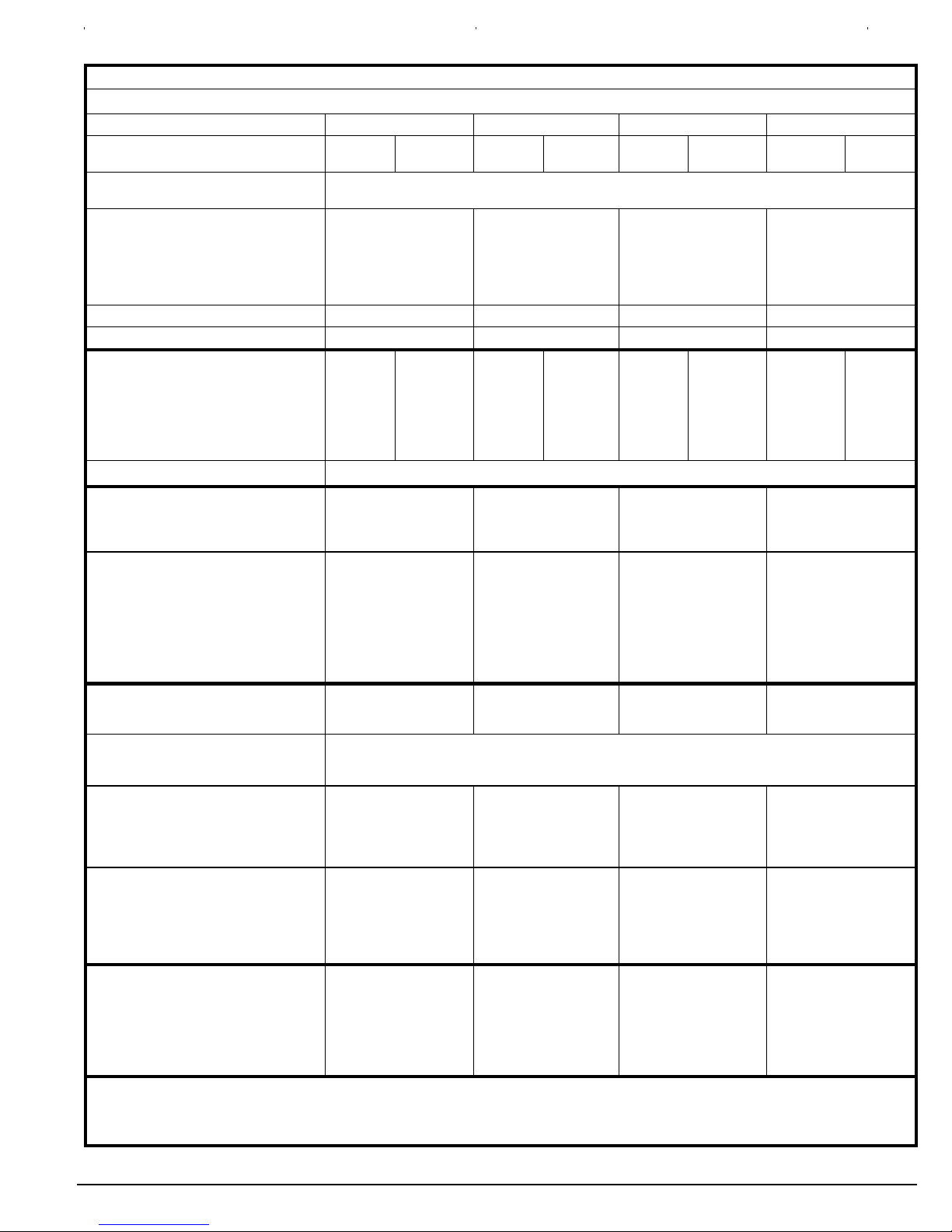
TECHNICAL SUPPORT
Manufacturers Number (Mfr No --SeeRatingPlate) ALL Models
Specifications
*9MPV050F12 *9MPV075F12 *9MPV100J20 *9MPV125L20
General
Gas Type
Transformer Size (VA)
T’stat Heat Anticipator
Input (Btuh) Std/Alt. HI Heat
LO Heat
Output (Btuh) Std/Alt. HI Heat
Tem p. Ri s e (
oF/o
LO Heat
C) HI Heat
LO Heat
Electrical (Volts/Hz) 115/60 115/60 115/60 115/60
Rating Plate Amps 9.5 11.4 14.6 15.4
Gas & Ignition
Gas Type
Std. Main Orifices (No/Size)
Gas Valve Honeywell
Regulation Type
Manifold Press. HI Heat (in wc/Pa)
LO Heat (in wc/Pa)
Ignition Type
Combustion
Flue Outlet Size (Inches)
Std. Outlet Temp (less than)
Comb. Blower (MFD/Volts)
@Blower/ @ Transition Box (HI Heat)
Std. Pressures in wc(Pa)
5′ No Elbows
40′ +5--90° DWV Elbows
@Blower/ @ Transition Box (LO Heat)
Std. Pressures in wc(Pa)
5′ No Elbows
40′ +5--90° DWV Elbows
Limits & Controls
Rollout Switch (
Limit Control Setting (
oF/o
C)
oF/o
C)
Furnace Control (Type)
Furnace Control On
(Timed--secs) Off
Std. Pressure Sw. in wc(Pa) Part No
(HI Heat)Blwer Switch Press (Close)
Blower Switch Pressure (Open)
(LO Heat)Trans Switch Press (Close)
Transition Switch Pressure (Open)
High Alt. Pressure Sw. in wc(Pa)
Part No
(HI Heat)Blwer Switch Press (Close)
Blower Switch Pressure (Open)
(LO Heat)Trans Switch Press (Close)
Transition Switch Pressure (Open)
Blower Data
Wheel Size D x W in(mm)
FLA Motor Amps/Max RPM
Motor Type/H.P.
Filter Type & Size in(mm) (qty)
Min. Cool Cap. (Tons)
Max. Cool Cap. (Tons)
Gas Conversion Kits All Models
Nat to Propane NAHA002LP (1172959*)
Propane to Nat NAHA002NG (1172961*)
*Order from Service Parts
Nat Propane Nat Propane Nat Propane Nat Propane
40
.50
Nat.
2/42
VR8205Q
SNAP
3.5/872
1.7/423
50,000
35,000
46,000
32,000
35--65/19--46
35--65/19--46
Propane
2/54
VR8205Q
SNAP
10.0/2490
4.9/1221
40--70/22--38
40--70/22--38
Nat.
3/42
VR8205Q
SNAP
3.5/872
1.7/423
75,000
52,500
70,000
48,000
Propane
3/54
VR8205Q
SNAP
10.0/2490
4.9/1221
40--70/22--38
40--70/22--38
Nat.
4/42
VR8205Q
SNAP
3.5/872
1.7/423
100,000
70,000
93,000
65,000
Propane
4/54
VR8205Q
SNAP
10.0/2490
4.9/1221
125,000
87,500
118,000
82,000
40--70/22--38
40--70/22--38
Nat.
5/42
VR8205Q
SNAP
3.5/872
1.7/423
Hot Surface
2
o
140
F/60oC
4/370
--1.80/--2.60(--448/--647)
--1.30/--2.30(--324/--573)
--1.20/--1.90(--299/--473)
--1.00/--1.80(--249/--448
300/149
260/127
--1.80/--2.60(--448/--647)
--1.30/--2.30(--324/--573)
--1.20/--1.90(--299/--473)
--1.00/--1.80(--249/--448
140
2
o
F/60oC
4/370
300/149
210/99
3
o
140
F/60oC
4/370
--1.80/--2.60(--448/--647)
--1.70/--2.50(--423/--623)
--1.20/--1.90(--299/--473)
--1.00/--1.80(--249/--448
300/149
240/116
3
o
140
F/60oC
4/370
--1.80/--2.60(--448/--647)
--1.70/--2.50(--423/--623)
--1.30/--2.30(--324/--573)
--1.20/--2.20(--299/--548)
300/149
190/88
Integrated
30 HI /45 LO
60,100,140,180
1013515
0.95(237)
0.80(199)
1.70(423)
1.50(374)
1013165
0.70(174)
0.55(137)
1.40(349)
1.20(299)
11 x 8(279 x 203)
7.7/1240
1
/
ECM/
16x25x1(406x635x25)
2
1.5
3
1013515
0.95(237)
0.80(199)
1.70(423)
1.50(374)
1013165
0.70(174)
0.55(137)
1.40(349)
1.20(299)
11 x 10(279 x 254)
9.6/1240
3
/
ECM/
16x25x1(406x635x25)
4
1.5
3
1013515
0.95(237)
0.80(199)
1.70(423)
1.50(374)
1013165
0.70(174)
0.55(137)
1.40(349)
1.20(299)
11 x 10(279 x 254)
12.8/1240
ECM/1
16x25x1(406x635x25) (2)
2
5
1013166
1.30(324)
1.10(274)
1.80(448)
1.60(398)
1013157
0.85(212)
0.70(174)
1.70(423)
1.50(374)
11 x 10(279 x 254)
12.8/1240
ECM/1
16x25x1(406x635x25) (2)
2
5
Propane
5/54
VR8205Q
SNAP
10.0/2490
4.9/1221
8
Specifications are subject to change without notice.
440 04 2024 01

Circulation Air Blower Data - *9MPV050
Cooling Adjustment Heating Rise Adjustment
DIP Switch
(OFF = 0 and
ON = 1)
High Cool @ .50
in wc(125 Pa)
Low Cool (80%
of High Cool)
** Adjust
Jumper
DIP Switch
(OFF = 0 and
Setting
5&6 CFM L/s CFM L/s 3&4
ON = 1)
High Heat
Rise
Change @
0.20 in wc
(50 Pa)
Low Heat
Rise
Change at
Resultant
Static
00 1246 588 997 471 + 00 -- 4 -- 3
*00 1211 571 969 457 *NOM *00 0 0
00 1122 529 898 424 -- 00 5 5
01 1105 521 884 417 + 01 3 4
01 1027 485 822 388 NOM 01 7 7
01 945 446 756 357 -- 01 13 14
10 892 421 714 337 + 10 -- 1 0
10 820 387 656 310 NOM 10 4 5
10 745 352 596 281 -- 10 9 9
11 688 325 550 260 + 11 -- 1 5 -- 1 5
11 609 287 487 230 NOM 11 -- 1 3 -- 1 2
11 541 255 433 204 -- 11 -- 9 -- 9
Airflow performance includes 1” washable filter media.
*Factory Setting
**Adjust Jumper Setting (+, NOM, --) is applied to both Cooling and Heating
Note 1: HP Mode Jumper provides a 10% reduction in airflow when in Comfort position and a call for low or high cooling is
present with the ”O” line off. This feature is to provide lower airflow for running in HP Heating Mode if desirable.
Note 2: DEHUM mode (24VAC on DEHUM terminal) provides a 20% airflow reduction during cooling calls.
Note 3: Low Heat ESP is a result of High Heat ESP (-- is decrease in rise).
Note 4: High and low heat rise values are approximate air temperature change from return air temperature when at factory
default settings.
Table 2 Airflow
DIP Switch
(OFF=0andON=1)
Continuous Fan @
0.10 in wc (25 Pa) ESP
1&2 CFM L/s
*00 592 279
01 1021 482
Table 3 SW2 DIP Assignments
DIP Switch Blower Parameter
1&2 Cont Fan Adj
3&4 Heat Speed Adj
5&6 Cool Speed Adj
7&8 Cool On/Off Delay
10 1346 635
11 1346 635
* Factory Setting
Table 4
DIP SW2 -- 7/8
(OFF=0andON=1)
ON DELAY OFF DELAY
Timed ON (sec)
Cooling Delay Options (SW2 -- 7, 8)
Airflow during on
delay
Timer OFF (sec)
Airflow during off
delay
*00 5 OFF 90 100%
01 5 OFF 0 OFF
10 30 50% 30 100%
11 30 50% 180 50%
Airflow % is of High Cool airflow demand determined from SW2--5/6 Table 1
Airflow resumes to 100% after on delay time is completed
Airflow stops (or switches to continuous fan speed) after off delay time is completed
* Factory Setting
MAX CFM (L/s) for Factory Washable Filters
Filter Size (in/mm) CFM L/s
14″ X25″ (356 x 635) 1400 661
16″ X25″ (406 x 635) 1600 755
20″ X25″ (508 x 635) 2000 944
24″ X25″ (610 x 635) 2500 1180
Max CFM (L/s) based on 600 FPM (3.0 m/s)
NOTE: Disposable filters are typically rated at 300 FPM (1.5 m/s).
These filters only allow half the airflow when compared to 600 FPM
(3.0 m/s) filters.
440 04 2024 01
Specifications are subject to change without notice.
9
1600
1400
1200
1000
CFM
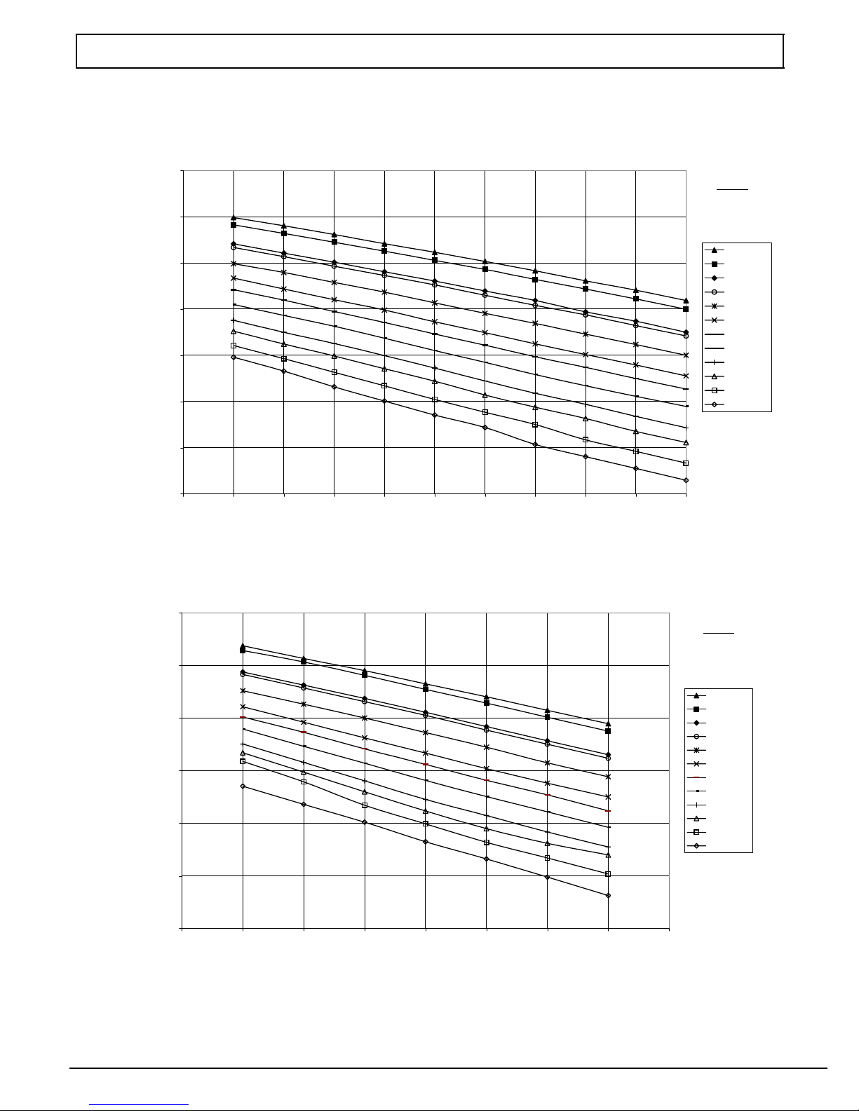
Circulation Air Blower Data - *9MPV050
Cooling Airflow Settings
High Cooling Airflows
*9MPV050F12
800
600
400
Legend
Airflow
Selection is
from Highest to
Lowest
00 (+)
00 (NOM)
00 (-)
01 (+)
01 (NOM)
01 (-)
10 (+)
10 (NOM)
10 (-)
11 (+)
11 (NOM)
11 (-)
200
0 0.1 0.2 0.3 0.4 0.5 0.6 0.7 0.8 0.9 1
ESP (in. w.c.)
Low Cooling Airflows
*9MPV050F12
1200
1000
800
600
CFM
400
200
Legend
Airflow
Selection is
from Highest to
Lowest
00 (+)
00 (NOM)
00 (-)
01 (+)
01 (NOM)
01 (-)
10 (+)
10 (NOM)
10 (-)
11 (+)
11 (NOM)
11 (-)
0
0 0.1 0.2 0.3 0.4 0.5 0.6 0.7 0.8
NOTE: OFF = 0 and ON = 1
10
ESP (in. w.c.)
Specifications are subject to change without notice.
440 04 2024 01

Circulation Air Blower Data - *9MPV075
Cooling Adjustment Heating Rise Adjustment
DIP Switch
(OFF = 0 and
ON = 1)
High Cool @ .50
in wc(125 Pa)
Low Cool (80%
of High Cool)
** Adjust
Jumper
DIP Switch
(OFF = 0 and
Setting
5&6 CFM L/s CFM L/s 3&4
ON = 1)
High Heat
Rise
Change @
0.20 in wc
(50 Pa)
Low Heat
Rise
Change at
Resultant
Static
00 1342 633 1074 507 + 00 -- 4 -- 4
*00 1210 571 968 457 *NOM *00 0 0
00 1053 497 842 397 -- 00 5 4
01 1135 536 908 429 + 01 1 1
01 1020 481 816 385 NOM 01 6 5
01 872 412 698 329 -- 01 12 10
10 965 455 772 364 + 10 -- 1 -- 1
10 840 396 672 317 NOM 10 3 3
10 680 321 544 256 -- 10 9 8
11 708 334 566 267 + 11 -- 6 -- 6
11 590 278 472 223 NOM 11 -- 2 -- 3
11 488 230 390 184 -- 11 3 2
Airflow performance includes 1” washable filter media.
*Factory Setting
**Adjust Jumper Setting (+, NOM, --) is applied to both Cooling and Heating
Note 1: HP Mode Jumper provides a 10% reduction in airflow when in Comfort position and a call for low or high cooling is
present with the ”O” line off. This feature is to provide lower airflow for running in HP Heating Mode if desirable.
Note 2: DEHUM mode (24VAC on DEHUM terminal) provides a 20% airflow reduction during cooling calls.
Note 3: Low Heat ESP is a result of High Heat ESP (-- is decrease in rise).
Note 4: High and low heat rise values are approximate air temperature change from return air temperature when at factory
default settings.
Table 2 Airflow
DIP Switch
(OFF=0andON=1)
Continuous Fan @
0.10 in wc (25 Pa) ESP
1&2 CFM L/s
*00 612 289
01 1096 517
Table 3 SW2 DIP Assignments
DIP Switch Blower Parameter
1&2 Cont Fan Adj
3&4 Heat Speed Adj
5&6 Cool Speed Adj
7&8 Cool On/Off Delay
10 1403 662
11 1403 662
* Factory Setting
Table 4
DIP SW2 -- 7/8
(OFF=0andON=1)
ON DELAY OFF DELAY
Timed ON (sec)
Cooling Delay Options (SW2 -- 7, 8)
Airflow during on
delay
Timer OFF (sec)
Airflow during off
delay
*00 5 OFF 90 100%
01 5 OFF 0 OFF
10 30 50% 30 100%
11 30 50% 180 50%
Airflow % is of High Cool airflow demand determined from SW2--5/6 Table 1
Airflow resumes to 100% after on delay time is completed
Airflow stops (or switches to continuous fan speed) after off delay time is completed
* Factory Setting
MAX CFM (L/s) for Factory Washable Filters
Filter Size (in/mm) CFM L/s
14″ X25″ (356 x 635) 1400 661
16″ X25″ (406 x 635) 1600 755
20″ X25″ (508 x 635) 2000 944
24″ X25″ (610 x 635) 2500 1180
Max CFM (L/s) based on 600 FPM (3.0 m/s)
NOTE: Disposable filters are typically rated at 300 FPM (1.5 m/s).
These filters only allow half the airflow when compared to 600 FPM
(3.0 m/s) filters.
440 04 2024 01
Specifications are subject to change without notice.
11

1800
1600
1400
1200
1000
CFM
Circulation Air Blower Data - *9MPV075
Cooling Airflow Settings
High Cooling Airflows
*9MPV075F12
800
600
400
Legend
Airflow
Selection is
from Highest to
Lowest
00 (+)
00 (NOM)
01 (+)
00 (-)
01 (NOM)
10 (+)
01 (-)
10 (NOM)
11 (+)
10 (-)
11 (NOM)
11 (-)
200
0 0.1 0.2 0.3 0.4 0.5 0.6 0.7 0.8 0.9 1
ESP (in. w.c.)
Low Cooling Airflows
*9MPV075F12
1400
1200
1000
800
CFM
600
400
200
Legend
Airflow
Selection is
from Highest to
Lowest
00 (+)
00 (NOM)
01 (+)
00 (-)
01 (NOM)
10 (+)
01 (-)
10 (NOM)
11 (+)
10 (-)
11 (NOM)
11 (-)
0
0 0.1 0.2 0.3 0.4 0.5 0.6 0.7 0.8
NOTE: OFF = 0 and ON = 1
12
ESP (in. w.c.)
Specifications are subject to change without notice.
440 04 2024 01

Circulation Air Blower Data - *9MPV100
Cooling Adjustment Heating Rise Adjustment
DIP Switch
(OFF = 0 and
ON = 1)
High Cool @ .50
in wc(125 Pa)
Low Cool (80%
of High Cool)
** Adjust
Jumper
DIP Switch
(OFF = 0 and
Setting
5&6 CFM L/s CFM L/s 3&4
ON = 1)
High Heat
Rise
Change @
0.20 in wc
(50 Pa)
Low Heat
Rise
Change at
Resultant
Static
00 2144 1012 1715 809 + 00 -- 4 -- 4
*00 2013 950 1610 760 *NOM *00 0 0
00 1842 869 1474 696 -- 00 5 5
01 1772 836 1418 669 + 01 2 1
01 1624 766 1299 613 NOM 01 8 7
01 1471 694 1177 555 -- 01 14 14
10 1367 645 1094 516 + 10 0 -- 1
10 1227 579 982 463 NOM 10 6 5
10 1077 508 862 407 -- 10 13 11
11 930 439 744 351 + 11 -- 6 -- 7
11 808 380 646 305 NOM 11 -- 2 -- 2
11 634 299 507 239 -- 11 3 3
Airflow performance includes 1” washable filter media.
*Factory Setting
**Adjust Jumper Setting (+, NOM, --) is applied to both Cooling and Heating
Note 1: HP Mode Jumper provides a 10% reduction in airflow when in Comfort position and a call for low or high cooling is
present with the ”O” line off. This feature is to provide lower airflow for running in HP Heating Mode if desirable.
Note 2: DEHUM mode (24VAC on DEHUM terminal) provides a 20% airflow reduction during cooling calls.
Note 3: Low Heat ESP is a result of High Heat ESP (-- is decrease in rise).
Note 4: High and low heat rise values are approximate air temperature change from return air temperature when at factory
default settings.
Table 2 Airflow
DIP Switch
(OFF=0andON=1)
Continuous Fan @
0.10 in wc (25 Pa) ESP
1&2 CFM L/s
*00 1007 475
01 1742 822
Table 3 SW2 DIP Assignments
DIP Switch Blower Parameter
1&2 Cont Fan Adj
3&4 Heat Speed Adj
5&6 Cool Speed Adj
7&8 Cool On/Off Delay
10 2204 1040
11 2204 1040
* Factory Setting
Table 4
DIP SW2 -- 7/8
(OFF=0andON=1)
ON DELAY OFF DELAY
Timed ON (sec)
Cooling Delay Options (SW2 -- 7, 8)
Airflow during on
delay
Timer OFF (sec)
Airflow during off
delay
*00 5 OFF 90 100%
01 5 OFF 0 OFF
10 30 50% 30 100%
11 30 50% 180 50%
Airflow % is of High Cool airflow demand determined from SW2--5/6 Table 1
Airflow resumes to 100% after on delay time is completed
Airflow stops (or switches to continuous fan speed) after off delay time is completed
* Factory Setting
MAX CFM (L/s) for Factory Washable Filters
Filter Size (in/mm) CFM L/s
14″ X25″ (356 x 635) 1400 661
16″ X25″ (406 x 635) 1600 755
20″ X25″ (508 x 635) 2000 944
24″ X25″ (610 x 635) 2500 1180
Max CFM (L/s) based on 600 FPM (3.0 m/s)
NOTE: Disposable filters are typically rated at 300 FPM (1.5 m/s).
These filters only allow half the airflow when compared to 600 FPM
(3.0 m/s) filters.
440 04 2024 01
Specifications are subject to change without notice.
13

2700
A
2200
1700
CFM
1200
Circulation Air Blower Data - *9MPV100
Cooling Airflow Settings
High Cooling Airflows
*9MPV100J20
Legend
Airflow
Selection is
from Highest to
Lowest
00 (+)
00 (NOM)
00 (-)
01 (+)
01 (NOM)
01 (-)
10 (+)
10 (NOM)
10 (-)
11 (+)
11 (NOM)
11 (-)
700
200
0 0.1 0.2 0.3 0.4 0.5 0.6 0.7 0.8 0.9 1
ESP (in. w.c.)
Low Cooling Airflows
*9MPV100J20
2000
1800
1600
1400
1200
1000
CFM
800
600
400
Legend
irflow Selection
is from Highest
to Lowest
00 (+)
00 (NOM)
00 (-)
01 (+)
01 (NOM)
01 (-)
10 (+)
10 (NOM)
10 (-)
11 (+)
11 (NOM)
11 (-)
200
0
0 0.1 0.2 0.3 0.4 0.5 0.6 0.7 0.8
NOTE: OFF = 0 and ON = 1
14
ESP (in. w.c.)
Specifications are subject to change without notice.
440 04 2024 01

Circulation Air Blower Data - *9MPV125
Cooling Adjustment Heating Rise Adjustment
DIP Switch
(OFF = 0 and
ON = 1)
High Cool @ .50
in wc(125 Pa)
Low Cool (80%
of High Cool)
** Adjust
Jumper
DIP Switch
(OFF = 0 and
Setting
5&6 CFM L/s CFM L/s 3&4
ON = 1)
High Heat
Rise
Change @
0.20 in wc
(50 Pa)
Low Heat
Rise
Change at
Resultant
Static
00 2150 1015 1720 812 + 00 -- 4 -- 4
*00 2025 956 1620 764 *NOM *00 0 0
00 1856 876 1485 700 -- 00 4 5
01 1755 828 1404 663 + 01 1 2
01 1615 762 1292 610 NOM 01 6 7
01 1452 685 1162 548 -- 01 12 13
10 1338 631 1070 505 + 10 -- 1 0
10 1201 567 961 454 NOM 10 3 4
10 1069 504 855 403 -- 10 9 10
11 909 429 727 343 + 11 -- 6 -- 6
11 800 377 640 302 NOM 11 -- 3 -- 3
11 627 296 502 237 -- 11 3 3
Airflow performance includes 1” washable filter media.
*Factory Setting
**Adjust Jumper Setting (+, NOM, --) is applied to both Cooling and Heating
Note 1: HP Mode Jumper provides a 10% reduction in airflow when in Comfort position and a call for low or high cooling is
present with the ”O” line off. This feature is to provide lower airflow for running in HP Heating Mode if desirable.
Note 2: DEHUM mode (24VAC on DEHUM terminal) provides a 20% airflow reduction during cooling calls.
Note 3: Low Heat ESP is a result of High Heat ESP (-- is decrease in rise).
Note 4: High and low heat rise values are approximate air temperature change from return air temperature when at factory
default settings.
Table 2 Airflow
DIP Switch
(OFF=0andON=1)
Continuous Fan @
0.10 in wc (25 Pa) ESP
1&2 CFM L/s
*00 1032 487
01 1778 839
Table 3 SW2 DIP Assignments
DIP Switch Blower Parameter
1&2 Cont Fan Adj
3&4 Heat Speed Adj
5&6 Cool Speed Adj
7&8 Cool On/Off Delay
10 2178 1028
11 2178 1028
* Factory Setting
Table 4
DIP SW2 -- 7/8
(OFF=0andON=1)
ON DELAY OFF DELAY
Timed ON (sec)
Cooling Delay Options (SW2 -- 7, 8)
Airflow during on
delay
Timer OFF (sec)
Airflow during off
delay
*00 5 OFF 90 100%
01 5 OFF 0 OFF
10 30 50% 30 100%
11 30 50% 180 50%
Airflow % is of High Cool airflow demand determined from SW2--5/6 Table 1
Airflow resumes to 100% after on delay time is completed
Airflow stops (or switches to continuous fan speed) after off delay time is completed
* Factory Setting
MAX CFM (L/s) for Factory Washable Fil-
ters
Filter Size (in/mm) CFM L/s
14″ X25″ (356 x 635) 1400 661
16″ X25″ (406 x 635) 1600 755
20″ X25″ (508 x 635) 2000 944
24″ X25″ (610 x 635) 2500 1180
Max CFM (L/s) based on 600 FPM (3.0 m/s)
NOTE: Disposable filters are typically rated at 300 FPM (1.5 m/s).
These filters only allow half the airflow when compared to 600 FPM
(3.0 m/s) filters.
440 04 2024 01
Specifications are subject to change without notice.
15

2700
2200
1700
CFM
1200
Circulation Air Blower Data - *9MPV125
Cooling Airflow Setting
High Cooling Airflows
*9MPV125L20
Legend
Airflow
Selection is
from Highest to
Lowest
00 (+)
00 (NOM)
00 (-)
01 (+)
01 (NOM)
01 (-)
10 (+)
10 (NOM)
10 (-)
11 (+)
11 (NOM)
11 (-)
700
CFM
200
0 0.1 0.2 0.3 0.4 0.5 0.6 0.7 0.8 0.9 1
ESP (in. w.c.)
Low Cooling Airflows
*9MPV125L20
2000
1800
1600
1400
1200
1000
800
600
400
Legend
Airflow
Selection is
from Highest to
Lowest
00 (+)
00 (NOM)
00 (-)
01 (+)
01 (NOM)
01 (-)
10 (+)
10 (NOM)
10 (-)
11 (+)
11 (NOM)
11 (-)
200
0
0 0.1 0.2 0.3 0.4 0.5 0.6 0.7 0.8
NOTE: OFF = 0 and ON = 1
16
ESP (in. w.c.)
Specifications are subject to change without notice.
440 04 2024 01

*9MPV & *9MVX Parts
MM
PP
M
F
B
A
V
GG
EE
14
17
FF
Y
X
UU
VV
W
18
24
25
DD
CC
10
9
KK
2
5
QQ
SSHRR
TT
2
XX
T
J
K
K
U
S
22
R
P
21
3
4
NN
HH
20
OO
(2) CELL MODEL ONLY
24
*9MVX040 UNIT ONLY
23
8
6
Representative drawing only, some models may vary in appearance.
GG
13
16
FF
YY
440 04 2024 01
15
WW
16
12
BB
LL
N
Specifications are subject to change without notice.
Q
JJ
11
L
ZZ
17

Replacement Parts - *9MPV
Models -- *9MPV050F12D1, *9MPV075F12D1, *9MPV100J20D1 & *9MPV125L20D1 (Natural Gas)
Replacement part supplied will be current active part. For parts not listed, consult place of purchase.
Key
No.
1 Heat Exchanger, Primary 1012850
2 Ht Exchanger, Secondary 1013762
3 Motor, Blower 1172828
4
5 Wheel, Blower 1013011
6 Transformer 1172810 1 1 1 1
8 Control 1175594 1 1 1 1
9 Switch, Interlock 1171981 1 1 1 1
10 Switch, Pressure 1013166
11 Blower, Exhaust 1172826
12 Valve, Gas Nat. 2 Stg 1172822 1 1 1 1
13 Flame Sensor 1172827 1 1 1 1
14 Igniter 1172533 1 1 1 1
15 Orifice, Burner #42 Nat. 1011351 2 3 4 5
16 Switch, Limit (Rollout) 1013102 2 2 2 2
17 Burner Assembly 1172884
18 Switch, Limit (Main) 1320366
20 Filter,HH 16X25X1/2” 1010365 1 1 2 2
22 Board, Tap Select Interface 1174894 1 1 1 1
21 Control, Motor Variable Spd 1174887
23 Choke, Power 1172838 -- -- 1 1
*See Table below for bellyband
location on motor
Model *9MPV inches mm
040F12 13/
060F12 27/
080J20 27/
100L20 27/
Description
Functional
Mount, Motor kit*
Bellyband Location
on Motor -- A Dimensions
8
8
8
8
Part
Number
1012854
1012858
1012862
1013763
1013765
1013767
11728291--
1014822 1 1 1 1
11721291--
1013515--1
11728251--
1172965
1172966
1172967
34335001
1320367
1008445
1174888
1174889
1174895
34.9
73
73
73
050
F12
1
--
--
-1
--
--
--
1
--
--
-1
--
--
--
1
--
--
--
075
F12
*9MPV
-1
--
--
-1
--
--
-1
-1
-1
1
--
-1
--
--
-1
--
--
-1
--
--
100
J20
--
-1
--
--
-1
--
-1
-1
-1
1
--
--
-1
--
--
-1
--
--
-1
--
125
L20
Key
No.
--
--
--
1
--
--
-1
-1
-1
1
--
-1
--
--
-1
--
--
-1
--
--
-1
A Panel, Top 1012866
B Gasket, Top Panel 1012603
F Partition, Blower 1172008
H Housing, Blower 1172885
J Panel, Blower Cutoff 721020013
K Hanger, Blower 1012328 2 2 2 2
L Door, Blwer (Cmaker only)
M Bracket Asy., Door Filler 1172232
N Door, Front (Cmaker only)
P Transition Assembly 1172228
Q Gasket, Exhaust Blower 1014425 1 1 1 1
R Board, Insulating 1012418
S Box, Collector 1012244
T Gasket, Transition 1013263
U Gasket, Collector Box 1012594
Description
(Cmaker only)
(Cmaker only)
(Heil only)
(Heil only)
(Heil only)
(Tstar only)
(Tstar only)
(Tstar only)
(Cmaker only)
Cmaker only)
(Heil only)
(Heil only)
(Heil only)
(Tstar only)
(Tstar only)
(Tstar only)
Part
Number
1012867
1012868
1012604
1012605
1172005
1172006
1172007
11729691--
7210200081--
1175025
1175026
1175042
1175028
1175029
1175043
1175031
1175032
1175044
1172233
1172234
1013148
1013149
1013150
1013145
1013146
1013147
1173086
1173087
1173088
1172229
1172230
1012419
1012420
1012245
1012246
1013080
1013083
1013084
1012595
1012596
050
F12
1
--
--
1
--
--
1
--
--
--
1
--
-1
--
-1
--
--
1
--
--
1
--
-1
--
-1
--
--
1
--
--
1
--
--
1
--
--
1
--
--
--
1
--
--
*9MPV
075
F12
1
--
--
1
--
--
--
1
--
--
--
1
--
1
1
--
--
1
--
--
1
--
--
1
--
--
1
--
--
1
--
--
1
--
--
1
--
--
1
--
--
1
--
--
--
1
--
--
1
--
--
100
J20
125
L20
--
--
1
--
--
1
--
--
1
--
--
1
--
--
--
--
1
--
--
1
--
--
1
1
--
--
1
1
--
--
1
--
--
1
--
--
1
--
--
1
--
--
1
--
--
1
--
--
1
--
--
1
--
--
1
--
--
1
--
--
1
--
--
1
--
--
1
--
--
1
--
--
1
--
--
1
--
--
1
--
--
1
--
--
1
--
--
1
--
--
--
--
1
--
--
1
--
--
1
--
--
1
18
A
Specifications are subject to change without notice
440 04 2024 01

Replacement Parts - *9MPV
Models -- *9MPV050F12D1, *9MPV075F12D1, *9MPV100J20D1 & *9MPV125L20D1 (Natural Gas)
Replacement part supplied will be current active part. For parts not listed, consult place of purchase.
*9MPV
075
F12
Key
No.
V Partition, Front Ht Exchger 1012650
W Gasket, Attachment Plate 1012542
X Cover, Junction Box 1012350 1 1 1 1
Y Box, Junction 1172860 1 1 1 1
BB Manifold 1012970
CC Bottom, Burner Box 1172847
DD Baffle, Burner Box 1012338
EE Top, Burner Box 1013702
FF Bracket, Manifold Support 1012377 2 2 2 2
GG Bracket, Burner Box Side 1012532 2 2 2 2
HH Bracket, Control Mounting 1172845 1 1 1 1
JJ Tube, Sensor 1172238
KK Trap, Drain Assembly 1171917 1 1 1 1
LL Sightglass
MM Wrapper, Filter Rack 741010039 1 1 2 2
NN Front, Filter Rack 741020001 1 1 2 2
OO Cover, Filter 2791043 1 1 2 2
PP Clip, Filter 1008482 3 3 3 3
QQ Gasket, Trap 1013701 1 1 1 1
RR Bracket, Trap 1171986 1 1 1 1
SS Gasket, Trap Bracket 1171987 1 1 1 1
TT Tube, Drain Coll. Box5/8″ ID 1172245 1 1 1 1
UU Tube, Drain Tee1/2″ ID 1171989 1 1 1 1
VV Tube, Relief 1172012 1 1 1 1
WW Drain Vent 1014003 1 1 1 1
XX Clip, Retainer 1175788 1 1 1 1
YY Tee, Drain 1171915 1 1 1 1
ZZ Sightglass 1172768 1 1 1 1
Description
(Tstar only)
Part
Number
1012648
1012651
1012653
1012543
1012544
1012545
1012971
1012278
1012279
1172848
1172849
1172850
1012339
1012340
1013703
1013704
117224111
1013235
101323611
050
F12
1
--
--
--
2
--
--
--
1
--
--
--
1
--
--
--
1
--
--
1
--
--
075
F12
-1
--
--
-2
--
--
-1
--
--
-1
--
--
1
--
--
1
--
--
1
1
1
1
*9MPV
100
J20
125
L20
--
-1
--
--
-2
--
--
-1
--
--
-1
--
-1
--
-1
--
1
1
1
1
Key
No.
)( PART NOT ILLUSTRATED
-)( Door Screws 1014488 4 4 4 4
--
--
)( Door Screw Grommets 1171990 4 4 4 4
1
)( Coupling, Air Intake 1012284 1 1 1 1
--
)( Gasket, Air Intake 1012583 1 1 1 1
-)( Clamp, Hose5/8” 1012975 4 4 4 4
-)( Clamp, Hose3/4” 1012976 2 2 2 2
2
)( Coupling, Discharge 1002522 1 1 1 1
)( Clamp Hose 1013830 2 2 2 2
)( Grommet, Vent 1012697 1 1 1 1
-)( Bushing, Strain Relief 1945287 1 1 1 1
--
--
)( Grommet, Vinyl (Gas Inlet) 1009535 1 1 1 1
1
)( Harness, Wire 1172818 1 1 1 1
--
)( Harness, Wire Blower V.S. 1174758 1 1 1 1
-)( Trap, Drain Tee 1171916 1 1 1 1
-)( Tube, Drain1/2”IDDrain 1171991 1 1 1 1
1
)( Tube,1/2” Elbow 1171992 2 2 2 2
-)( Coupling,1/2” Barbed 1171993 1 1 1 1
--
1
)( Tubing,5/8”IDDrain 1171994 1 1 1 1
--
)( Connector,3/4”X1/2” 1171995 1 1 1 1
-)( Elbow,1/2” CPVC street 1171996 1 1 1 1
1
)( Grommet, Casing 1171997 1 1 1 1
)( Tube, Relief Ext. 1172239 1 1 1 1
)( Connector, Relief Tube 1171998 1 1 1 1
)( Plate, Cover 1171999 1 1 1 1
)( Gasket, Cover Plate 1172000 1 1 1 1
1
1
)( Cap, Drain Tee 1172255 1 1 1 1
)( Clamp, Tee Cap 1172256 1 1 1 1
)( Manual, Users 44102201200 1 1 1 1
1
1
)( Manual, Installation 44001202401 1 1 1 1
)( Manual, Technical 44004202401 1 1 1 1
Gas Conversion Kits -- All models
Nat to Propane NAHA002LP (1172959*)
Propane to Nat NAHA002NG (1172961*)
* Must be ordered from Service Parts
Description
Part
Number
050
F12
100
J20
125
L20
440 04 2024 01
Specifications are subject to change without notice.
19

TECHNICAL SUPPORT
Manufacturers Number (Mfr No --SeeRatingPlate)
ALL Models
Specifications
*9MVX040F12 *9MVX060F12 *9MVX080J20 *9MVX100L20
General
Gas Type
Transformer Size (VA)
T’stat Heat Anticipator
Input (Btuh) Std/Alt. HI Heat
LO Heat
Output (Btuh) Std/Alt. HI Heat
Tem p. Ri s e (
oF/o
LO Heat
C) HI Heat
LO Heat
Electrical (Volts/Hz) 115/60 115/60 115/60 115/60
Rating Plate Amps 9.5 11. 4 14.6 14.6
Gas & Ignition
Gas Type
Std. Main Orifices (qty/size)
Gas Valve Honeywell
Regulation Type
Manifold Press. HI Heat (in wc/Pa)
LO Heat (in wc/Pa)
Nat Propane Nat Propane Nat Propane Nat Propane
40
.50
25--55/14--31
25--55/14--31
Nat.
2/44
VR8205Q
SNAP
3.5/872
1.7/423
40000
28000
38000
27000
Propane
2/55
VR8205Q
SNAP
10/2490
4.9/1221
30--60/17--33
30--60/17--33
Nat.
3/44
VR8205Q
SNAP
3.5/872
1.7/423
60000
42000
58000
41000
Propane
3/55
VR8205Q
SNAP
10/2490
4.9/1221
30--60/17--33
30--60/17--33
Nat.
4/44
VR8205Q
SNAP
3.5/872
1.7/423
80000
56000
77000
54000
Propane
4/55
VR8205Q
SNAP
10/2490
4.9/1221
100000
70000
96000
67000
30--60/17--33
30--60/17--33
Nat.
5/44
VR8205Q
SNAP
3.5/872
1.7/423
Propane
5/55
VR8205Q
SNAP
10/2490
4.9/1221
Ignition Type Hot Surface
Combustion
Flue Outlet Size inches(mm)
Std. Outlet Temp (less than)
Comb. Blower (MFD/Volts)
(oF/o
2(50.8)
C)
140/60
4/370
2(50.8)
140/60
4/370
@Blower/ @ Transition Box (HI Heat)
Std. Pressures -- in wc(Pa)
54 No Elbows
404 +5--905 DWV Elbows
2.10/3.47(523/864)
--3.38/--1.90(--842/--473)
2.26/3.52(563/877)
--2.77/--1.52(--690/--378)
--3.28/--1.93(--817/--481)
@Blower/ @ Transition Box (LO Heat)
Std. Pressures -- in wc(Pa)
54 No Elbows
404 +5--905 DWV Elbows
Limits & Controls
Rollout Switch (
Limit Control Setting (
oF/o
C)
oF/o
C)
Furnace Control (Type)
Furnace Control On
(Timed--secs) Off
Std. Pressure Sw. -- in wc(Pa) Part No
(HI Heat)Blwer Switch Press (Close)
Blower Switch Pressure (Open)
(LO Heat)Trans Switch Press (Close)
Transition Switch Pressure (Open)
High Alt Pressure Sw.--in wc(Pa) Part No
(HI Heat)Blwer Switch Press (Close)
Blower Switch Pressure (Open)
(LO Heat)Trans Switch Press (Close)
Transition Switch Pressure (Open)
1.38/2.29(344/570)
--2.21/--1.22(--550/--304)
300/149
210/99
1177762
0.65(162)
0.50(125)
1.85(461)
2.11(525)
1177766
0.65(162)
0.50(125)
1.58(393)
1.40(349)
1.50/2.35(374/585)
--2.06/--1.16(--513/--289)
300/149
230/110
30 HI /45 LO
60,100,140,180
1177767
0.58(144)
0.43(107)
1.73(431)
1.70(423)
1177767
0.58(144)
0.43(107)
1.48(369)
1.31(326)
--2.34/--1.33(--583/--331)
Integrated
Blower Data
Wheel Size D x W in(mm)
FLA Motor Amps/Max RPM
Motor Type/H.P.
Filter Type & Size (qty.) Permanent -- in(mm)
Min. Cool Cap. (Tons)
Max. Cool Cap. (Tons)
11 x 8(279 x 203)
1
ECM/
/
16x25x1(406x635x25)
2
1.5
3
11 x 10(279 x 254)
3
ECM/
/
16x25x1(406x635x25)
4
1.5
3
16x25x1(406x635x25) (2)
Gas Conversion Kits All Models
Nat to Propane NAHA00601LP
Propane to Nat NAHA00601NG
3(76.2)
140/60
4/370
2.05/3.34(510/832)
1.55/2.45(386/610)
300/149
240/116
1177764
0.95(237)
0.80(199)
1.89(471)
1.55(386)
1177768
0.95(237)
0.80(199)
1.61(401)
1.43(356)
11 x 10(279 x 254)
ECM/1
2
5
3(76.2)
140/60
4/370
2.34/3.45(583/859)
--3.29/--2.16(--819/--538)
1.84/2.70(458/672)
--2.61/--1.72(--650/--428)
300/149
180/82
1177765
1.56(396)
1.38(344)
2.32(578)
1.66(413)
1177769
1.30(324)
1.14(384)
1.97(491)
1.78(443)
11 x 10(279 x 254)
ECM/1
16x25x1(406x635x25) (2)
2
5
20
Specifications are subject to change without notice.
440 04 2024 01

Circulation Air Blower Data - *9MVX040
Cooling Adjustment Heating Rise Adjustment
DIP Switch
(OFF = 0
ON = 1)
High Cool @ .50
in wc(125 Pa)
Low Cool (80%
of High Cool)
** Adjust
Jumper
DIP Switch
Setting
5&6 CFM L/s CFM L/s 3&4
(OFF = 0
ON = 1)
High Heat
Rise
Change @
0.20 in wc
(50 Pa)
Low Heat
Rise
Change at
Resultant
Static
00 1244 587 995 470 + 00 -- 3 -- 3
*00 1206 569 965 455 *NOM *00 0 0
00 1126 531 901 425 -- 00 4 4
01 1109 523 887 419 + 01 2 2
01 1032 487 826 390 NOM 01 6 6
01 941 444 753 355 -- 01 13 10
10 901 425 721 340 + 10 0 -- 1
10 828 391 662 313 NOM 10 3 3
10 757 357 606 286 -- 10 8 7
11 705 333 564 266 + 11 -- 1 2 -- 1 3
11 633 299 506 239 NOM 11 -- 1 0 -- 1 0
11 556 262 445 210 -- 11 -- 8 -- 8
Airflow performance includes 1” washable filter media.
*Factory Setting
**Adjust Jumper Setting (+, NOM, --) is applied to both Cooling and Heating
Note 1: HP Mode Jumper provides a 10% reduction in airflow when in Comfort position and a call for low or high cooling is
present with the ”O” line off. This feature is to provide lower airflow for running in HP Heating Mode if desirable.
Note 2: DEHUM mode (24VAC on DEHUM terminal) provides a 20% airflow reduction during cooling calls.
Note 3: Low Heat ESP is a result of High Heat ESP (-- is decrease in rise).
Note 4: High and low heat rise values are approximate air temperature change from return air temperature when at factory
default settings.
Table 2 Airflow
DIP Switch
(OFF = 0 / ON = 1)
Continuous Fan @
0.10 in wc (25 Pa) ESP
1&2 CFM L/s
*00 592 279
01 1021 482
Table 3 SW2 DIP Assignments
DIP Switch Blower Parameter
1&2 Cont Fan Adj
3&4 Heat Speed Adj
5&6 Cool Speed Adj
7&8 Cool On/Off Delay
10 1346 635
11 1346 635
* Factory Setting
Table 4
DIP SW2 -- 7/8
(OFF = 0 / ON = 1)
ON DELAY OFF DELAY
Timed ON (sec)
Cooling Delay Options (SW2 -- 7, 8)
Airflow during on
delay
Timer OFF (sec)
Airflow during off
delay
*00 5 OFF 90 100%
01 5 OFF 0 OFF
10 30 50% 30 100%
11 30 50% 180 50%
Airflow % is of High Cool airflow demand determined from SW2--5/6 Table 1
Airflow resumes to 100% after on delay time is completed
Airflow stops (or switches to continuous fan speed) after off delay time is completed
* Factory Setting
MAX CFM (L/s) for Factory Washable Filters
Filter Size (in/mm) CFM L/s
14″ X25″ (356 x 635) 1400 661
16″ X25″ (406 x 635) 1600 755
20″ X25″ (508 x 635) 2000 944
24″ X25″ (610 x 635) 2500 1180
Max CFM (L/s) based on 600 FPM (3.0 m/s)
NOTE: Disposable filters are typically rated at 300 FPM (1.5 m/s).
These filters only allow half the airflow when compared to 600 FPM
(3.0 m/s) filters.
440 04 2024 01
Specifications are subject to change without notice.
21

1400
1200
1000
CFM
Circulation Air Blower Data - *9MVX040
Cooling Airflow Settings
*9MVX040F12
High Cool Airflow
800
600
400
200
00 +
00 NOM
00 01 +
01 NOM
01 10 +
10 NOM
10 11 +
11 NOM
11 -
0
0.0 0.1 0.2 0.3 0.4 0.5 0.6 0.7 0.8 0.9 1.0
ESP (inches of wc)
*9MVX040F12
Low Cool Airflow
1200
1000
800
600
CFM
400
200
00 +
00 NOM
00 01 +
01 NOM
01 10 +
10 NOM
10 11 +
11 NOM
11 -
0
0.0 0.1 0.2 0.3 0.4 0.5 0.6 0.7 0.8 0.9 1.0
NOTE: OFF = 0 and ON = 1
22
ESP ( inches of wc)
Specifications are subject to change without notice.
440 04 2024 01

Circulation Air Blower Data - *9MVX060
Cooling Adjustment Heating Rise Adjustment
DIP Switch
(OFF = 0
ON = 1)
High Cool @ .50
in wc(125 Pa)
Low Cool (80%
of High Cool)
** Adjust
Jumper
DIP Switch
Setting
5&6 CFM L/s CFM L/s 3&4
(OFF = 0
ON = 1)
High Heat
Rise
Change @
0.20 in wc
(50 Pa)
Low Heat
Rise
Change at
Resultant
Static
00 1377 650 1102 650 + 00 -- 3 -- 3
*00 1239 585 991 585 *NOM *00 0 0
00 1097 518 878 518 -- 00 3 3
01 1165 550 932 550 + 01 1 2
01 1044 493 835 493 NOM 01 4 4
01 889 420 711 420 -- 01 8 8
10 966 456 773 456 + 10 -- 1 0
10 848 400 678 400 NOM 10 2 2
10 715 337 572 337 -- 10 7 7
11 74 353 599 353 + 11 -- 5 -- 4
11 650 307 520 307 NOM 11 -- 2 -- 2
11 523 247 418 247 -- 11 1 1
Airflow performance includes 1” washable filter media.
*Factory Setting
**Adjust Jumper Setting (+, NOM, --) is applied to both Cooling and Heating
Note 1: HP Mode Jumper provides a 10% reduction in airflow when in Comfort position and a call for low or high cooling is
present with the ”O” line off. This feature is to provide lower airflow for running in HP Heating Mode if desirable.
Note 2: DEHUM mode (24VAC on DEHUM terminal) provides a 20% airflow reduction during cooling calls.
Note 3: Low Heat ESP is a result of High Heat ESP (-- is decrease in rise).
Note 4: High and low heat rise values are approximate air temperature change from return air temperature when at factory
default settings.
Table 2 Airflow
DIP Switch
(OFF = 0 / ON = 1)
Continuous Fan @
0.10 in wc (25 Pa) ESP
1&2 CFM L/s
*00 612 475
01 1096 822
Table 3 SW2 DIP Assignments
DIP Switch Blower Parameter
1&2 Cont Fan Adj
3&4 Heat Speed Adj
5&6 Cool Speed Adj
7&8 Cool On/Off Delay
10 1403 1040
11 1403 1040
* Factory Setting
Table 4
DIP SW2 -- 7/8
(OFF = 0 / ON = 1)
ON DELAY OFF DELAY
Timed ON (sec)
Cooling Delay Options (SW2 -- 7, 8)
Airflow during on
delay
Timer OFF (sec)
Airflow during off
delay
*00 5 OFF 90 100%
01 5 OFF 0 OFF
10 30 50% 30 100%
11 30 50% 180 50%
Airflow % is of High Cool airflow demand determined from SW2--5/6 Table 1
Airflow resumes to 100% after on delay time is completed
Airflow stops (or switches to continuous fan speed) after off delay time is completed
* Factory Setting
MAX CFM (L/s) for Factory Washable Fil-
ters
Filter Size (in/mm) CFM L/s
14″ X25″ (356 x 635) 1400 661
16″ X25″ (406 x 635) 1600 755
20″ X25″ (508 x 635) 2000 944
24″ X25″ (610 x 635) 2500 1180
Max CFM (L/s) based on 600 FPM (3.0 m/s)
NOTE: Disposable filters are typically rated at 300 FPM (1.5 m/s).
These filters only allow half the airflow when compared to 600 FPM
(3.0 m/s) filters.
440 04 2024 01
Specifications are subject to change without notice.
23

CFM
Circulation Air Blower Data - *9MVX060
Cooling Airflow Settings
*9MVX060F12
High Cool Ai r flow chart
1800
1600
1400
1200
1000
800
600
400
200
00+
00NOM
0001+
01NOM
0110+
10NOM
1011+
11NOM
11-
0
0 0.1 0.2 0.3 0.4 0.5 0.6 0.7 0.8 0.9 1
ESP (inches of wc)
*9M VX06 0F12
Low Cool Airflow chart
1400
1200
1000
800
CFM
600
400
200
00+
00NOM
0001+
01NOM
0110+
10NOM
1011+
11NOM
11-
0
0 0.1 0.2 0.3 0.4 0.5 0.6 0.7
NOTE: OFF = 0 and ON = 1
24
ESP (inches of wc)
Specifications are subject to change without notice.
440 04 2024 01

Circulation Air Blower Data - *9MVX080
Cooling Adjustment Heating Rise Adjustment
DIP Switch
(OFF = 0
ON = 1)
High Cool @ .50
in wc(125 Pa)
Low Cool (80%
of High Cool)
** Adjust
Jumper
DIP Switch
Setting
5&6 CFM L/s CFM L/s 3&4
(OFF = 0
ON = 1)
High Heat
Rise
Change @
0.20 in wc
(50 Pa)
Low Heat
Rise
Change at
Resultant
Static
00 2146 1013 1717 1013 + 00 -- 3 -- 3
*00 2009 948 1607 948 *NOM *00 0 0
00 1843 870 1474 870 -- 00 5 5
01 1779 840 1423 840 + 01 3 3
01 1645 776 1316 776 NOM 01 6 8
01 1498 707 1198 707 -- 01 11 11
10 1409 665 1127 665 + 10 0 0
10 1294 611 1035 611 NOM 10 6 4
10 1147 541 918 541 -- 10 10 9
11 1005 474 804 474 + 11 -- 5 -- 6
11 887 419 710 419 NOM 11 -- 2 -- 2
11 757 357 606 357 -- 11 3 2
Airflow performance includes 1” washable filter media.
*Factory Setting
**Adjust Jumper Setting (+, NOM, --) is applied to both Cooling and Heating
Note 1: HP Mode Jumper provides a 10% reduction in airflow when in Comfort position and a call for low or high cooling is
present with the ”O” line off. This feature is to provide lower airflow for running in HP Heating Mode if desirable.
Note 2: DEHUM mode (24VAC on DEHUM terminal) provides a 20% airflow reduction during cooling calls.
Note 3: Low Heat ESP is a result of High Heat ESP (-- is decrease in rise).
Note 4: High and low heat rise values are approximate air temperature change from return air temperature when at factory
default settings.
Table 2 Airflow
DIP Switch
(OFF = 0 / ON = 1)
Continuous Fan @
0.10 in wc (25 Pa) ESP
1&2 CFM L/s
*00 1007 475
01 1742 822
Table 3 SW2 DIP Assignments
DIP Switch Blower Parameter
1&2 Cont Fan Adj
3&4 Heat Speed Adj
5&6 Cool Speed Adj
7&8 Cool On/Off Delay
10 2204 1040
11 2204 1040
* Factory Setting
Table 4
DIP SW2 -- 7/8
(OFF = 0 / ON = 1)
ON DELAY OFF DELAY
Timed ON (sec)
Cooling Delay Options (SW2 -- 7, 8)
Airflow during on
delay
Timer OFF (sec)
Airflow during off
delay
*00 5 OFF 90 100%
01 5 OFF 0 OFF
10 30 50% 30 100%
11 30 50% 180 50%
Airflow % is of High Cool airflow demand determined from SW2--5/6 Table 1
Airflow resumes to 100% after on delay time is completed
Airflow stops (or switches to continuous fan speed) after off delay time is completed
* Factory Setting
MAX CFM (L/s) for Factory Washable Fil-
ters
Filter Size (in/mm) CFM L/s
14″ X25″ (356 x 635) 1400 661
16″ X25″ (406 x 635) 1600 755
20″ X25″ (508 x 635) 2000 944
24″ X25″ (610 x 635) 2500 1180
Max CFM (L/s) based on 600 FPM (3.0 m/s)
NOTE: Disposable filters are typically rated at 300 FPM (1.5 m/s).
These filters only allow half the airflow when compared to 600 FPM
(3.0 m/s) filters.
440 04 2024 01
Specifications are subject to change without notice.
25

2400
2000
1600
1200
CFM
Circulation Air Blower Data - *9MVX080
Cooling Airflow Settings
*9MVX080J20
High Cool Airflows
00 +
00 NOM
00 01 +
01 NOM
0110 +
10 NOM
10 11 +
11 NOM
11 -
800
400
0
0.0 0.1 0.2 0.3 0.4 0.5 0.6 0.7 0.8 0.9 1.0
ESP (inches of wc)
*9MVX 080J20
Low Cool A irflow
2000
1800
1600
1400
1200
1000
CFM
800
600
400
00 +
00 NOM
00 01 +
01 NOM
01 10 +
10 NOM
10 11 +
11 NOM
11 -
200
0
0.0 0.1 0.2 0.3 0.4 0.5 0.6 0.7 0.8 0.9 1.0
NOTE: OFF = 0 and ON = 1
26
ES P (inches of wc)
Specifications are subject to change without notice.
440 04 2024 01

Circulation Air Blower Data - *9MVX100
Cooling Adjustment Heating Rise Adjustment
DIP Switch
(OFF = 0
ON = 1)
High Cool @ .50
in wc(125 Pa)
Low Cool (80%
of High Cool)
** Adjust
Jumper
DIP Switch
Setting
5&6 CFM L/s CFM L/s 3&4
(OFF = 0
ON = 1)
High Heat
Rise
Change @
0.20 in wc
(50 Pa)
Low Heat
Rise
Change at
Resultant
Static
00 2108 995 1686 995 + 00 -- 3 -- 3
*00 1974 932 1579 932 *NOM *00 0 0
00 1812 855 1450 855 -- 00 4 5
01 1712 808 1370 808 + 01 1 1
01 1587 749 1270 749 NOM 01 4 5
01 1422 671 1138 671 -- 01 9 10
10 1312 619 1050 619 + 10 -- 2 -- 1
10 1197 565 958 565 NOM 10 1 2
10 1056 498 845 498 -- 10 5 7
11 919 434 735 434 + 11 -- 5 -- 6
11 797 376 638 376 NOM 11 -- 3 -- 3
11 641 303 513 303 -- 11 2 2
Airflow performance includes 1” washable filter media.
*Factory Setting
**Adjust Jumper Setting (+, NOM, --) is applied to both Cooling and Heating
Note 1: HP Mode Jumper provides a 10% reduction in airflow when in Comfort position and a call for low or high cooling is
present with the ”O” line off. This feature is to provide lower airflow for running in HP Heating Mode if desirable.
Note 2: DEHUM mode (24VAC on DEHUM terminal) provides a 20% airflow reduction during cooling calls.
Note 3: Low Heat ESP is a result of High Heat ESP (-- is decrease in rise).
Note 4: High and low heat rise values are approximate air temperature change from return air temperature when at factory
default settings.
Table 2 Airflow
DIP Switch
(OFF = 0 / ON = 1)
Continuous Fan @
0.10 in wc (25 Pa) ESP
1&2 CFM L/s
*00 1032 487
01 1778 839
Table 3 SW2 DIP Assignments
DIP Switch Blower Parameter
1&2 Cont Fan Adj
3&4 Heat Speed Adj
5&6 Cool Speed Adj
7&8 Cool On/Off Delay
10 2178 1028
11 2178 1028
* Factory Setting
Table 4
DIP SW2 -- 7/8
(OFF = 0 / ON = 1)
ON DELAY OFF DELAY
Timed ON (sec)
Cooling Delay Options (SW2 -- 7, 8)
Airflow during on
delay
Timer OFF (sec)
Airflow during off
delay
*00 5 OFF 90 100%
01 5 OFF 0 OFF
10 30 50% 30 100%
11 30 50% 180 50%
Airflow % is of High Cool airflow demand determined from SW2--5/6 Table 1
Airflow resumes to 100% after on delay time is completed
Airflow stops (or switches to continuous fan speed) after off delay time is completed
* Factory Setting
MAX CFM (L/s) for Factory Washable Fil-
ters
Filter Size (in/mm) CFM L/s
14″ X25″ (356 x 635) 1400 661
16″ X25″ (406 x 635) 1600 755
20″ X25″ (508 x 635) 2000 944
24″ X25″ (610 x 635) 2500 1180
Max CFM (L/s) based on 600 FPM (3.0 m/s)
NOTE: Disposable filters are typically rated at 300 FPM (1.5 m/s).
These filters only allow half the airflow when compared to 600 FPM
(3.0 m/s) filters.
440 04 2024 01
Specifications are subject to change without notice.
27

CFM
2600
2200
1800
1400
1000
600
Circulation Air Blower Data - *9MVX100
Cooling Airflow Settings
*9MVX 100L20
High Cooling Airflows
00 (+)
00 (NOM)
00(-)
01(+)
01(NOM)
01(-)
10(+)
10(NOM)
10(-)
11(+)
11(NOM)
11(-)
200
0.0 0.1 0.2 0.3 0.4 0.5 0.6 0.7 0.8 0.9 1.0
ESP (inches of wc)
*9MVX100L20
Low Cool Airflow
2000
1800
1600
1400
1200
1000
CFM
800
600
400
00+
00NOM
0001+
01 NOM
01 10+
10 NOM
10 11+
11 NOM
11 -
200
0
0.0 0.2 0.4 0.6 0.8 1.0
NOTE: OFF = 0 and ON = 1
28
ESP (inches of wc)
Specifications are subject to change without notice.
440 04 2024 01

Variable Speed (9MPV & 9MVX) Tap Select Interface Board (TSIB)
TO FURNACE BOARD
P3
BLU WHT
GRN BLK
BRN YEL
TO FURNACE
CONTROL24VAC
FROM 24V
TRANS RED
ON = 1
18
OFF
= 0
J1
+NOM --
P7
RED
SW2
1234 6578
ON
OFF
CONT
HEAT
FAN
+NOM--
BLOWER ADJUST
COOL
COOL
DLY
J1
J2
AC/HP EFFICIENCY
HP COMFORT
SELECTION
HP MODE
SELECT
Y1
O
SW2
1234 6578
CONT
FAN
HEAT
COOL
COOL
DLY
BLOWER ADJUST
INCREASE/NO CHANGE/DECREASE
J2
AC/HP EFFICIENCY
HP COMFORT
HP MODE
SELECT
HEAT PUMP EFFICIENCY OR
HP COMFORT SELECTION
CONTINUOUS
CFM SELECT
HEATING RISE
SELECT
COOLING CFM
SELECT
COOLING ON/OFF
DELAY PROFILES
25--25--54
440 04 2024 01
International Comfort Products, LLC
Lewisburg, TN 37091 U.S.A.
Specifications are subject to change without notice.
29

Replacement Parts - *9MVX
Models -- *9MVX040F12A1, *9MVX060F12A1, *9MVX080J20A1 & *9MVX100L20A1 (Natural Gas)
Replacement part supplied will be current active part. For parts not listed, consult place of purchase.
A
060
F12
*9MVX
-1
--
--
-1
--
--
-1
-1
-1
--
--
-1
--
--
-1
--
--
-1
--
--
-1
--
--
080
J20
--
-1
--
--
-1
--
-1
-1
--
-1
--
--
-1
--
--
-1
--
--
-1
--
--
-1
--
Key
No.
1 Heat Exchanger, Primary 1012850
2 Ht Exchanger, Secondary 1177461
3 Motor, Blower 1172828
4
5 Wheel, Blower 1013011
6 Transformer 1172810 1 1 1 1
8 Control 1175594 1 1 1 1
9 Switch, Interlock 1171981 1 1 1 1
10 Switch, Pressure 1177762
11 Blower, Exhaust 1177466
12 Valve, Gas Nat. Two--Stg 1172822 1 1 1 1
13 Flame Sensor 1172827 1 1 1 1
14 Igniter 1172533 1 1 1 1
15 Orifice, Burner #44 Nat. 1013797 2 3 4 5
16 Switch, Limit (Rollout) 1013102 2 2 2 2
17 Burner Assembly 1172884
18 Switch, Limit (Main) 1320366
20 Filter,HH 16X25X1/2” 1010365 1 1 2 2
22 Board, Tap Select Interface 1174894 1 1 1 1
21 Control, Motor Variable Spd 1174887
23 Choke, Power 1172838 -- -- 1 1
24 Baffle, Flue 1177823 1 -- -- -24 Baffle, Right 1177824 -- 1 1 1
25 Baffle, Left 1177825 -- 1 1 1
*See Table below for bellyband
location on motor
Model *9MVX inches mm
040F12 13/
060F12 27/
080J20 27/
100L20 27/
Description
Functional
Mount, Motor kit*
Bellyband Location
on Motor -- A Dimensions
8
8
8
8
Part
Number
1012854
1012858
1012862
1013763
1013765
1013767
11728291-1014822 1 1 1 1
11721291--
1177763
1177764
1177765
1177467
1177468
1177469
1172965
1172966
1172967
1320361
1320367
1008445
1174888
1174889
1174895
34.9
73
73
73
040
F12
1
--
--
-1
--
--
--
1
--
--
-1
--
--
--
1
--
--
-1
--
--
--
1
--
--
--
100
L20
Key
No.
--
--
-1
--
--
-1
-1
-1
--
--
-1
--
--
-1
--
--
-1
--
--
-1
--
--
-1
A Panel, Top 1012866
B Gasket, Top Panel 1012603
F Partition, Blower 1172008
H Housing, Blower 1172885
J Panel, Blower Cutoff 721020013
K Hanger, Blower 1012328 2 2 2 2
L Door, Blwer (Cmaker only)
M Bracket Asy., Door Filler 1172232
N Door, Front (Cmaker only)
P Transition Assembly 1172228
Q Gasket, Exhaust Blower 1014425 1 1 1 1
R Board, Insulating 1012418
S Box, Collector 1012244
T Gasket, Transition 1013263
U Gasket, Collector Box 1012594
Description
(Cmaker only)
(Cmaker only)
(Heil only)
(Heil only)
(Heil only)
(Tstar only)
(Tstar only)
(Tstar only)
(Cmaker only)
Cmaker only)
(Heil only)
(Heil only)
(Heil only)
(Tstar only)
(Tstar only)
(Tstar only)
Part
Number
1012867
1012868
1012604
1012605
1172005
1172006
1172007
11729691--
7210200081--
1175025
1175026
1175042
1175028
1175029
1175043
1175031
1175032
1175044
1172233
1172234
1013148
1013149
1013150
1013145
1013146
1013147
1173086
1173087
1173088
1172229
1172230
1012419
1012420
1012245
1012246
1013080
1013083
1013084
1012595
1012596
040
F12
1
--
--
1
--
--
1
--
--
--
1
--
-1
--
-1
--
--
1
--
--
1
--
-1
--
-1
--
--
1
--
--
1
--
--
1
--
--
1
--
--
--
1
--
--
*9MVX
060
F12
1
--
--
1
--
--
--
1
--
--
--
1
--
1
1
--
--
1
--
--
1
--
--
1
--
--
1
--
--
1
--
--
1
--
--
1
--
--
1
--
--
1
--
--
--
1
--
--
1
--
--
080
J20
100
L20
--
--
1
--
--
1
--
--
1
--
--
1
--
--
--
--
1
--
--
1
--
--
1
1
--
--
1
1
--
--
1
--
--
1
--
--
1
--
--
1
--
--
1
--
--
1
--
--
1
--
--
1
--
--
1
--
--
1
--
--
1
--
--
1
--
--
1
--
--
1
--
--
1
--
--
1
--
--
1
--
--
1
--
--
1
--
--
1
--
--
--
--
1
--
--
1
--
--
1
--
--
1
30
Specifications are subject to change without notice.
440 04 2024 01

Replacement Parts - *9MVX
Models -- *9MVX040F12A1, *9MVX060F12A1, *9MVX080J20A1 & *9MVX100L20A1 (Natural Gas)
Replacement part supplied will be current active part. For parts not listed, consult place of purchase.
*9MVX
060
F12
Key
No.
V Partition, Front Ht Exchger 1012650
W Gasket, Attachment Plate 1012542
X Cover, Junction Box 1012350 1 1 1 1
Y Box, Junction 1172860 1 1 1 1
BB Manifold 1012970
CC Bottom, Burner Box 1172847
DD Baffle, Burner Box 1012338
EE Top, Burner Box 1013702
FF Bracket, Manifold Support 1012377 2 2 2 2
GG Bracket, Burner Box Side 1012532 2 2 2 2
HH Bracket, Control Mounting 1172845 1 1 1 1
JJ Tube, Sensor 1172238
KK Trap, Drain Assembly 1171917 1 1 1 1
LL Sightglass
MM Wrapper, Filter Rack 741010039 1 1 2 2
NN Front, Filter Rack 741020001 1 1 2 2
OO Cover, Filter 2791043 1 1 2 2
PP Clip, Filter 1008482 3 3 3 3
QQ Gasket, Trap 1013701 1 1 1 1
RR Bracket, Trap 1171986 1 1 1 1
SS Gasket, Trap Bracket 1171987 1 1 1 1
TT Tube, Drain Coll. Box5/8″ ID 1172245 1 1 1 1
UU Tube, Drain Tee1/2″ ID 1171989 1 1 1 1
VV Tube, Relief 1172012 1 1 1 1
WW Drain Vent 1014003 1 1 1 1
XX Clip, Retainer 1175788 1 1 1 1
YY Tee, Drain 1171915 1 1 1 1
ZZ Sightglass 1172768 1 1 1 1
Description
(Tstar only)
Part
Number
1012648
1012651
1012653
1012543
1012544
1012545
1012971
1012278
1012279
1172848
1172849
1172850
1012339
1012340
1013703
1013704
117224111
1013235
101323611
040
F12
1
--
--
--
2
--
--
--
1
--
--
--
1
--
--
--
1
--
--
1
--
--
060
F12
-1
--
--
-2
--
--
-1
--
--
-1
--
--
1
--
--
1
--
--
1
1
1
1
*9MVX
080
J20
100
L20
--
-1
--
--
-2
--
--
-1
--
--
-1
--
-1
--
-1
--
1
1
1
1
Key
No.
)( PART NOT ILLUSTRATED
-)( Door Screws 1014488 4 4 4 4
--
--
)( Door Screw Grommets 1171990 4 4 4 4
1
)( Coupling, Air Intake 1012284 1 1 1 1
--
)( Gasket, Air Intake 1012583 1 1 1 1
-)( Clamp, Hose5/8” 1012975 4 4 4 4
-)( Clamp, Hose3/4” 1012976 2 2 2 2
2
)( Coupling, Discharge 1002522 1 1 1 1
)( Clamp Hose 1013830 2 2 2 2
)( Grommet, Vent 1012697 1 1 1 1
-)( Bushing, Strain Relief 1945287 1 1 1 1
--
--
)( Grommet, Vinyl (Gas Inlet) 1009535 1 1 1 1
1
)( Harness, Wire 1172818 1 1 1 1
--
)( Harness, Wire Blower V.S. 1174758 1 1 1 1
-)( Trap, Drain Tee 1171916 1 1 1 1
-)( Tube, Drain1/2”IDDrain 1171991 1 1 1 1
1
)( Tube,1/2” Elbow 1171992 2 2 2 2
-)( Coupling,1/2” Barbed 1171993 1 1 1 1
--
1
)( Tubing,5/8”IDDrain 1171994 1 1 1 1
--
)( Connector,3/4”X1/2” 1171995 1 1 1 1
-)( Elbow,1/2” CPVC street 1171996 1 1 1 1
1
)( Grommet, Casing 1171997 1 1 1 1
)( Tube, Relief Ext. 1172239 1 1 1 1
)( Connector, Relief Tube 1171998 1 1 1 1
)( Plate, Cover 1171999 1 1 1 1
)( Gasket, Cover Plate 1172000 1 1 1 1
1
1
)( Cap, Drain Tee 1172255 1 1 1 1
)( Clamp, Tee Cap 1172256 1 1 1 1
)( Manual, Users 44102201200 1 1 1 1
1
1
)( Manual, Installation 44001202401 1 1 1 1
)( Manual, Technical 44004202401 1 1 1 1
Gas Conversion Kits -- All models
Nat to Propane NAHA00601LP
Propane to Nat NAHA00601NG
Description
Part
Number
040
F12
080
J20
100
L20
440 04 2024 01
Specifications are subject to change without notice.
31

Wiring Diagram *9MPV & *9MVX (Variable Speed Blower Motor)
32
Specifications are subject to change without notice.
440 04 2024 01
 Loading...