

International comfort products N9MP1, N9MP2, H9MPD, C9MPD, T9MPD Service Manual
MULTI POSITION
90% SINGLE STAGE
GAS FURNACES
Part Number
440 08 2011 00
N9MP1, N9MP2 & *9MPD
* Denotes brand H, C, T
Manufactured by:
This manual supports single stage “C” series and later condensing gas furnaces
© 2006 International Comfort Products LLC
2/2006

N9MP1 − Indoor combustion air (1 pipe only)
N9MP2 − Direct Vent ONLY (2 pipe only)
*9MPD − Dual Certified Venting (1 or 2 pipes)
* Denotes Brand (T, C or H)

Service Manual
Single Stage Multi Position Furnace
TABLE OF CONTENTS
1. INTRODUCTION 2. . . . . . . . . . . . . . . . . . . . . . . . . . . . . . . . . . . . . . . . . . . . . . . . . . . . . . . . . . . .
2. UNIT IDENTIFICATION 3. . . . . . . . . . . . . . . . . . . . . . . . . . . . . . . . . . . . . . . . . . . . . . . . . . . . .
3. FURNACE THEORY OF OPERATION 3. . . . . . . . . . . . . . . . . . . . . . . . . . . . . . . . . . . . . . . .
4. ELECTRICAL SUPPLY 4. . . . . . . . . . . . . . . . . . . . . . . . . . . . . . . . . . . . . . . . . . . . . . . . . . . . . .
5. INTERLOCK SWITCH 5. . . . . . . . . . . . . . . . . . . . . . . . . . . . . . . . . . . . . . . . . . . . . . . . . . . . . .
6. GAS SUPPLY 5. . . . . . . . . . . . . . . . . . . . . . . . . . . . . . . . . . . . . . . . . . . . . . . . . . . . . . . . . . . . . .
7. L.P. PRESSURE SWITCH 10. . . . . . . . . . . . . . . . . . . . . . . . . . . . . . . . . . . . . . . . . . . . . . . . . . .
8. HONEYWELL VR8205S GAS VALVE 11. . . . . . . . . . . . . . . . . . . . . . . . . . . . . . . . . . . . . . . . .
9. HIGH ALTITUDE OPERATION 11. . . . . . . . . . . . . . . . . . . . . . . . . . . . . . . . . . . . . . . . . . . . . . .
10. CHECKING TEMPERATURE RISE 11. . . . . . . . . . . . . . . . . . . . . . . . . . . . . . . . . . . . . . . . . .
11. ROOM THERMOSTATS 12. . . . . . . . . . . . . . . . . . . . . . . . . . . . . . . . . . . . . . . . . . . . . . . . . . . .
12. CONTROL WIRING 12. . . . . . . . . . . . . . . . . . . . . . . . . . . . . . . . . . . . . . . . . . . . . . . . . . . . . . .
13. TWINNING KITS 13. . . . . . . . . . . . . . . . . . . . . . . . . . . . . . . . . . . . . . . . . . . . . . . . . . . . . . . . . .
14. LIMIT SWITCHES 13. . . . . . . . . . . . . . . . . . . . . . . . . . . . . . . . . . . . . . . . . . . . . . . . . . . . . . . . .
15. PRESSURE SWITCHES 14. . . . . . . . . . . . . . . . . . . . . . . . . . . . . . . . . . . . . . . . . . . . . . . . . . .
16. HIGHER/LOWER NEGATIVE PRESSURES 16. . . . . . . . . . . . . . . . . . . . . . . . . . . . . . . . . .
17. VENT/COMBUSTION AIR PIPING 17. . . . . . . . . . . . . . . . . . . . . . . . . . . . . . . . . . . . . . . . . .
18. STANDARD VENT TERMINATION 17. . . . . . . . . . . . . . . . . . . . . . . . . . . . . . . . . . . . . . . . . .
19. CONCENTRIC VENT TERMINATION 21. . . . . . . . . . . . . . . . . . . . . . . . . . . . . . . . . . . . . . . .
20. COMBUSTION BLOWER 22. . . . . . . . . . . . . . . . . . . . . . . . . . . . . . . . . . . . . . . . . . . . . . . . . .
21. CONDENSATE DRAIN TRAP 23. . . . . . . . . . . . . . . . . . . . . . . . . . . . . . . . . . . . . . . . . . . . . . .
22. SEQUENCE OF OPERATION 24. . . . . . . . . . . . . . . . . . . . . . . . . . . . . . . . . . . . . . . . . . . . . .
23. CHECKING FLAME CURRENT 26. . . . . . . . . . . . . . . . . . . . . . . . . . . . . . . . . . . . . . . . . . . . .
24. CAPACITORS 26. . . . . . . . . . . . . . . . . . . . . . . . . . . . . . . . . . . . . . . . . . . . . . . . . . . . . . . . . . . .
25. BLOWER ASSEMBLY 26. . . . . . . . . . . . . . . . . . . . . . . . . . . . . . . . . . . . . . . . . . . . . . . . . . . . .
BLOWER PERFORMANCE DATA 29. . . . . . . . . . . . . . . . . . . . . . . . . . . . . . . . . . . . . . . . . . . . . .
WIRING DIAGRAM 30. . . . . . . . . . . . . . . . . . . . . . . . . . . . . . . . . . . . . . . . . . . . . . . . . . . . . . . . . . .
TECHNICAL SERVICE DATA (N9MP1 C1) 31. . . . . . . . . . . . . . . . . . . . . . . . . . . . . . . . . . . . . . .
TECHNICAL SERVICE DATA (N9MP2 C1) 32. . . . . . . . . . . . . . . . . . . . . . . . . . . . . . . . . . . . . . .
TECHNICAL SERVICE DATA (*9MPD C1) 33. . . . . . . . . . . . . . . . . . . . . . . . . . . . . . . . . . . . . .
TROUBLE SHOOTING GUIDE 34. . . . . . . . . . . . . . . . . . . . . . . . . . . . . . . . . . . . . . . . . . . . . . . . .
DIAGNOSTIC CODE SECTION 35. . . . . . . . . . . . . . . . . . . . . . . . . . . . . . . . . . . . . . . . . . . . . . . .
TROUBLE SHOOTING CHART #1 36. . . . . . . . . . . . . . . . . . . . . . . . . . . . . . . . . . . . . . . . . . . . . .
TROUBLE SHOOTING CHART #2 37. . . . . . . . . . . . . . . . . . . . . . . . . . . . . . . . . . . . . . . . . . . . . .
TROUBLE SHOOTING CHART #3 38. . . . . . . . . . . . . . . . . . . . . . . . . . . . . . . . . . . . . . . . . . . . . .
INDEX
40. . . . . . . . . . . . . . . . . . . . . . . . . . . . . . . . . . . . . . . . . . . . . . . . . . . . . . . . . . . . . . . . . . . . . .
Service Manual
Single Stage Multi Position Furnace
INTRODUCTION
This service manual is designed to be used in conjunction
with the installation manual and/or technical support manual provided with each furnace.
These furnaces represent the very latest in high efficiency
gas furnace technology. Consequently, they incorporate
the use of certain controls that contain highly sophisticated
electronic components which are not user serviceable.
Therefore, it is essential that only competent, qualified, service personnel attempt to install, service, or maintain this
product.
This Service manual was written to assist the professional
This service manual covers the following models;
*9MPD− − − − − − C or later, *9MP1 − − − − − − C or
later and *9MP2 − − − − − − C or later models. The overall
operation of all of these models is essentially the same.
This manual, therefore, will deal with all subjects in a general nature (I.E. all text will pertain to all models) unless that
subject is unique to a particular model or family, in which
case it will be so indicated.
It will be necessary then for you to accurately identify the
unit you are servicing, so you may be certain of a proper
diagnosis and repair. (See Unit Identification, Page 3)
HVAC service technician to quickly and accurately diagnose and repair any malfunction of this product.
SAFETY REQUIREMENTS
Recognize safety information. This is the safety−alert symbol . When you see this symbol on the furnace and in instructions manuals be alert to
the potential for personal injury.
Understand the signal words DANGER, WARNING, or CAUTION. These words are used with the safety−alert symbol. DANGER identifies the most
serious hazards, those that will result in severe personal injury or death. WARNING signifies a hazard that could result in personal injury or death.
CAUTION is used to identify unsafe practices that could result in minor personal injury or product and property damage. NOTE is used to highlight
suggestions that will result in enhanced installation, reliability, or operation.
Installing and servicing heating equipment can be hazardous due to gas and electrical components. Only trained and qualified personnel should
install, repair, or service heating equipment.
Untrained service personnel can perform basic maintenance functions such as cleaning and replacing air filters. All other operations must be performed by trained service personnel. When working on heating equipment, observe precautions in the literature, on tags, and on labels attached to or
shipped with the unit and other safety precautions that may apply.
Follow all safety codes. In the United States, follow all safety codes including the current edition National Fuel Gas Code (NFGC) ANSI
Z223.1−2002/NFPA No. 54−2002. In Canada, refer to the current edition of the National Standard of Canada Natural Gas and Propane Installation
Code (NSCNGPIC) CSA B149.1−05. Wear safety glasses and work gloves. Have fire extinguisher available during start−up and adjustment proce-
dures and service calls.
These instructions cover minimum requirements and conform to existing national standards and safety codes. In some instances, these instructions
exceed certain local codes and ordinances, especially those that may not have kept up with changing residential construction practices. We require
these instructions as a minimum for a safe installation.
!
4
c
International Comfort Products LLC
Lewisburg, TN 37091
440 08 2011 00
Single Stage Multi Position Furnace
UNIT IDENTIFICATION
Service Manual
The unit’s rating plate contains important information for the
service technician. It also lists the complete Model
Manufacturing and Serial Numbers.
placement parts (example, in certain model families a unit
having a MARKETING REVISION of “C” is likely to be
equipped with one or more different components.
These complete numbers are required to obtain correct re-
MODEL NUMBER IDENTIFICATION GUIDE
* 9 M P D 0 75 B 1 2 C 1
Brand Identifier Engineering Rev.
T = Tempstar Denotes major changes
C = Comfortmaker Marketing Digit
H = Heil Denotes major change
A = Arcoaire
N = Non−Brand Specific (Generic) Cooling Airflow
Brand Identifier 08 = 800 CFM
8 = Non−Condensing, 80+% Gas Furnace 12 = 1200 CFM
9 = Condensing, 90+% Gas Furnace 14 = 1400 CFM
Installation Configuration 16 = 1600 CFM
UP = Upflow DN = Downflow UH = Upflow/Horizontal 20 = 2000 CFM
HZ = Horizontal DH = Downflow/Horizontal
MP = Multiposition, Upflow/Downflow/Horizontal Cabinet Width
Major Design Feature B = 15.5″ Wide
1 = One (Single) Pipe N = Single Stage F = 19.1″ Wide
2 = Two Pipe P = PVC Vent J = 22.8″ Wide
D = 1 or 2 Pipe T = Two Stage L = 24.5″ Wide
L = Low NOx V = Variable Speed Input (Nominal MBTUH)
FURNACE THEORY OF OPERATION
The high efficiencies and lower profile (compared to past
series) of this furnace have been obtained using design
techniques not typical of traditional furnace designs. A brief
description of these new design techniques and the purpose they serve follows.
1. Reducing the height of the furnace while maintaining
the high efficiency of pervious models required maintaining the surface area of the heat exchanger and
yet minimizing the overall size.
The design required to achieve these results is the “SERPENTINE” design, wherein the flue gasses must follow a
serpent shaped passage through the heat exchanger via
convection.
This “Serpentine” path is resistive to normal convective
flow, and requires that a partial vacuum be created at the
outlet of the heat exchanger to maintain the flow of flue
products through the heat exchanger.
2. The serpentine heat exchanger design does not lend
itself well to the ribbon type, or slotted port type burner
found in more traditional design furnaces for the following reasons:
A. The secondary combustion airflows at right angles
to the burner flame, making it likely to “pull” the
flame off a ribbon or slotted port type burner.
B. The flame “height” of a ribbon or slotted port type
burner would make it difficult (if not impossible) to
prevent impingement of the flame on the heat exchanger surfaces whole maintaining the low profile
heat exchanger.
For these reasons, an “INSHOT” type burner is used in this
series. The inshot burner (also called a “jet” burner) fires a
flame straight out its end. This burner is designed to fire into
a tube style heat exchanger, making it an ideal application
in the tube−like passages of the serpentine heat exchanger.
3. In order to extract the maximum amount of heat possible from the flue gasses, a secondary heat exchanger (condenser) is connected to the outlet of the
primary heat exchanger. This condenser removes
additional heat from the flue gasses, causing their
temperature to drop below dew point. This results in
the forming of condensation (water) which then must
be routed to a drain.
4. The placement of the secondary heat exchanger at
the outlet of the primary heat exchanger creates additional resistance to the flow of gasses.
5. To overcome the resistance to convective flow of the
Primary and Secondary heat exchangers requires the
use of an Induced Draft Combustion Blower Assembly.
440 08 2011 00
5
Service Manual
Single Stage Multi Position Furnace
6. The Combustion Blower Assembly is mounted on the
outlet side of the Secondary heat exchanger, This
blower creates a partial vacuum (negative pressure)
within the heat exchangers drawing the flue products
out of the furnace.
7. A pressure switch (Air Proving Switch) is used as a
safety device that prevents the ignition system from
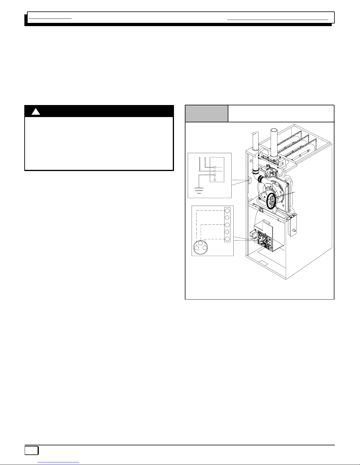
ELECTRICAL SUPPLY
!
ELECTRICAL SHOCK HAZARD.
Failure to turn off power could result in death or
personal injury.
Turn OFF electrical power at fuse box or service
panel before making any electrical connections
and ensure a proper ground connection is made
before connecting line voltage.
SUPPLY CIRCUIT
The furnace cannot be expected to operate correctly unless
it is properly connected (wired) to an adequately sized
single branch circuit. Line voltage wires should conform to
temperature limitation of 63° F (35° C) rise and be sized for
the unit maximum amps stated on the rating plate. Add the
full load amps for potential field − installed accessories that
would receive power from the furnace control. Consult NEC
or local codes for proper wire and circuit sizing.
WARNING
firing the furnace until it senses that a proper draft has
been established through the furnace.
SEQUENCE OF OPERATION − HEATING
Refer to the ignition control section for sequence of operation.
Figure 1
NOTE: Junction Box can be
mounted to either the left or right
side.
115V. 60 Hz
HOT
NEUT.
Connection
Box
Ground
Low Voltage
Terminal Board
W
R
G
Electrical Connections
W
BK
O
N
O
G
R
G
W
Y
G
FF
Models may
have 1 or 2
pressure
switches
SUPPLY VOLTAGE
Supply voltage to the furnace should be a nominal 115 volts.
It MUST be between 104 volts and 127 volts. Supply voltage to the furnace should be checked WITH THE FURNACE IN OPERATION. Voltage readings outside the specified range can be expected to cause operating problems.
Their cause MUST be investigated and corrected.
ELECTRICAL GROUND
Proper grounding of the electrical supply to THE FURNACE
IS REQUIRED for safety and operational reasons.
POLARITY
CORRECT POLARITY of the line voltage supply to the furnace is also required for safety and operational reasons.
The furnace control MUST have proper line voltage polarity
to operate properly.
25−24−90−2
NOTE: 115 VAC/60Hz/single−phase
Operating voltage range*: 127 VAC max, 104 VAC min.
* Permissible limits of voltage at which unit will operate satisfactorily
CHECKING GROUNDING AND POLARITY
Grounding may be verified as follows:
1. Turn the power supply “OFF”.
2. Using an Ohmmeter check for continuity between the
Neutral (white) wire and Ground wire (green) of the
supply circuit.
3. With the Ohmmeter set on the R x 1 scale, the read-
ing should be zero Ohms.
4. A zero Ohm reading indicates that the neutral is
grounded back to the main panel.
6
440 08 2011 00
Single Stage Multi Position Furnace
Service Manual
5. An alternate check would be to check for continuity
from the Neutral to a cold water pipe, (Pipe must be
metal, and must have a continuous, uninterrupted
connection to ground) or to a continuous, uninterrupted connection to ground) or to a driven ground
rod.
6. Any readings other than zero Ohms would indicate
a poor ground, or no ground.
Polarity may be verified as follows:
1. Turn the power supply “ON”.
2. Using a Voltmeter check for voltage between the Hot
(Black) and Neutral (White) wire of supply circuit.
3. Reading should be Line (Supply) Voltage.
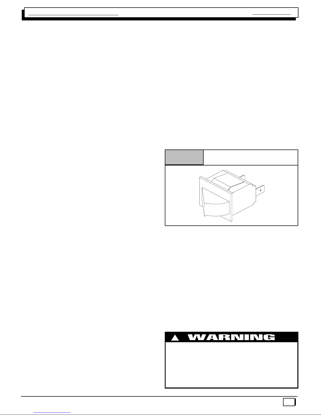
INTERLOCK SWITCH
The blower compartment door of all models is equipped
with an interlock switch. (See Figure 2) This switch is “Normally Open” (closes when the door is on the furnace) and
interrupts furnace operation when the door is open. This interlock switch is a safety device, and SHOULD NEVER BE
BY−PASSED.
Since this is a single pole switch, (breaking only one side of
the line) proper line polarity is essential to insure that furnace components are not “HOT” when switch is open. (See
Checking Grounding and Polarity)
4. Check for Voltage between the Neutral (White) wire
and Ground wire of the supply circuit.
5. Reading should be zero Volts. (if line voltage is read,
polarity is reversed)
6. A zero Volt reading indicates there is no voltage potential on Neutral wire.
7. Double check by checking for voltage between the
Hot (Black) wire and Ground wire of the supply circuit.
8. Reading should be Line (supply) Voltage. (if zero
volts is read, there is no ground, or polarity is reversed.)
Figure 2
Typical Interlock Switch
GAS SUPPLY
An adequately sized gas supply to the furnace is required
for proper operation. Gas piping which is undersized will not
provide sufficient capacity for proper operation. Piping
should be sized in accordance with accepted industry standards. Refer to NFGC and ANSI Z223.1 for proper gas pipe
size.
NATURAL GAS
Inlet (Supply) pressure to the furnace should be checked (at
the gas valve) with ALL OTHER GAS FIRED APPLIANCES
OPERATING. Inlet (Supply) pressure to the furnace under
these conditions MUST be within minimum and maximum
values listed on rating plate. If the inlet pressure is less, it
may be an indication of undersized piping or regulator problems.
10−12−96
L.P. GAS
Inlet (Supply) pressure to the furnace should be checked in
the same manner as for Natural Gas, however with L.P.
Gas, the inlet pressure MUST be a minimum of 11″ W.C. If
this cannot be obtained, problems are indicated in either the
regulator or pipe sizing.
CHECKING INPUT (FIRING) RATE
Once it has been determined that the gas supply is correct
to the furnace, it is necessary to check the input (firing) rate.
This can be done in two (2) ways. First by checking and adjusting (as necessary) the manifold (Outlet) pressure. The
second way is to “Clock” the gas meter.
!
FIRE OR EXPLOSION HAZARD.
Turn OFF gas at shut off before connecting
manometer.
Failure to turn OFF gas at shut off before
connecting manometer can result in death,
personal injury and/or property damage.
440 08 2011 00
7
Service Manual
Single Stage Multi Position Furnace
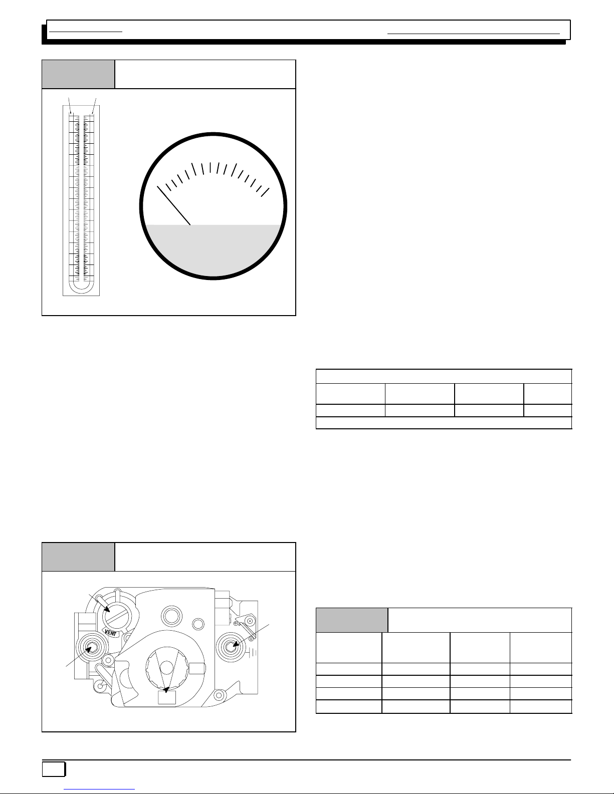
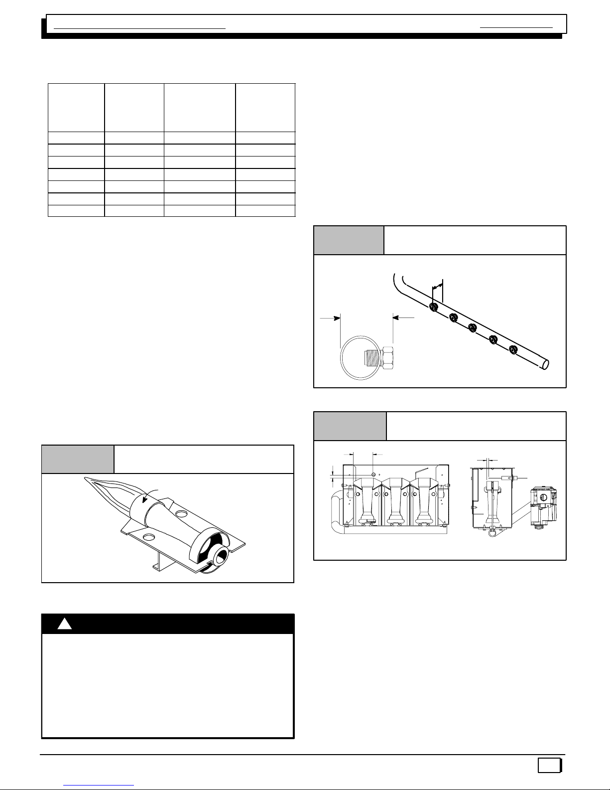
Figure 3
Pressure Connections
7
6
5
4
3
2
1
0
1
2
3
4
5
6
7
Typical U" Tube
Manometer
Gas Pressure Testing Devices
INCHES OF WATER
510
0
MAGNEHELIC
MAX. PRESSURE 15 PSIG
15
CHECKING MANIFOLD PRESSURE
NOTE: Make adjustment to manifold pressure with burners
operating.
1. Remove the burner compartment door.
2. With gas OFF, connect manometer to outlet tapped
opening on gas valve. Use manometer with a 0 to 15″
water column range.
3. Turn gas on. Remove the blower compartment door.
Operate the furnace by jumpering R to W on the furnace control board.
4. Remove manifold pressure adjustment screw cover
on furnace gas control valve. Turn adjusting screw
counterclockwise to decrease manifold pressure and
clockwise to increase pressure.
NOTE: Adjustment screw cover MUST be replaced on gas
control valve before reading manifold pressure and operating furnace.
5. Obtain gas heating value and installation site altitude.
6. Set manifold pressure to value shown in Table 2,
Table 3, Table 4 or Table 5.
7. When the manifold pressure is properly set, replace
the adjustment screw cover on the gas control valve.
8. Remove jumper wire from thermostat connection on
furnace control board. Remove manometer connection from manifold pressure tap, and replace plug in
valve.
9. Check for leaks at plug.
10. Replace the burner compartment and blower
compartment door.
Natural Gas Input Rating Check
NOTE: The gas meter can be used to measure input to furnace. Rating is based on a natural gas BTU content of 1,000
BTU’s per cubic foot. Check with gas supplier for actual
BTU content.
1. Make sure burner compartment door is in place before performing the following steps.
2. Turn OFF gas supply to all appliances and start fur-
nace.
Example
Natural Gas
BTU Content
1,000 3,600 48 75,000
No. of Seconds
Per Hour
1,000 x 3,600 ÷ 48 = 75,000 BTUH
Time Per Cubic
Foot in Seconds
BTU Per
Hour
3. Time how many seconds it takes the smallest (normally 1 cfh) dial on the gas meter to make one complete revolution. Refer to Example.
4. Relight all appliances and ensure all pilots are operating.
NOTE: If meter uses a 2 cubic foot dial, divide results (seconds) by two.
Alternate BTUH Input Ratings (USA Only)
Figure 4
Manifold Regulator
Adjustment
Under Cap
INLET
Inlet
Pressure
Tap 1/8 NPT
Typical Gas Control Valve Honeywell
HONEYWELL
V
T
ON
OFF
8
25−24−98a
Outlet
Pressure
Tap
1
/8 NPT
OUTLET
The input rating of these furnaces can be changed from the
standard input rating to the alternate input rating shown in
Table 1, by changing the main burner orifices. Changing of
burner orifices MUST be done by a qualified service technician. See section on changing orifices on page 9.
Table 1 Alternate Input Ratings, USA ONLY.
BTUH
Standard
Rating
50,000 40,000 #44 #55
75,000 60,000 #44 #55
100,000 80,000 #44 #55
125,000
BTUH
Alternate
Rating
100,000 #44 #55
Natural
Gas
Orifice*
Gas
Orifice**
LP
* See Table 4 for High Altitude.
** See Table 5 for High Altitude
440 08 2011 00
Single Stage Multi Position Furnace
MANIFOLD PRESSURE AND ORIFICE SIZE FOR HIGH ALTITUDE APPLICATIONS
Service Manual
Table 2
HEATING
VALUE
at ALTITUDE
BTU/CU. FT.
700 −− −− −− −− −− −− −− −− −− −− −− −− 41 3.7
725 −− −− −− −− −− −− −− −− −− −− 41 3.7 41 3.4
750 −− −− −− −− −− −− −− −− −− −− 41 3.5 42 3.6
775 −− −− −− −− −− −− −− −− 41 3.6 42 3.6 42 3.3
800 −− −− −− −− −− −− 41 3.6 42 3.7 42 3.4 42 3.1
825 −− −− −− −− 41 3.7 41 3.4 42 3.5 42 3.2 42 2.9
850 −− −− −− −− 41 3.5 42 3.6 42 3.3 42 3.0 42 2.8
875 −− −− 41 3.6 42 3.6 42 3.4 42 3.1 42 2.8 42 2.6
900 −− −− 42 3.7 42 3.4 42 3.2 42 2.9 42 2.7 42 2.5
925 41 3.7 42 3.5 42 3.3 42 3.0 42 2.8 42 2.5 44 3.3
950 41 3.5 42 3.3 42 3.1 42 2.9 42 2.6 42 2.4 44 3.1
975 42 3.7 42 3.2 42 2.9 42 2.7 42 2.5 44 3.2 45 3.6
1000 42 3.5 42 3.0 42 2.8 42 2.6 42 2.4 45 3.7 45 3.4
1050 42 3.2 42 2.7 42 2.5 44 3.3 45 3.6 −− −− −− −−
1100 43 3.6 42 2.5 44 3.2 45 3.6 −− −− −− −− −− −−
NATURAL GAS MANIFOLD PRESSURE ( w.c.)
MEAN ELEVATION FEET ABOVE SEA LEVEL
Orifice
No.
0 to
2000
Manifold
Pressure
Orifice
No.
2001 to
3000
Manifold
Pressure
Orifice
No.
3001 to
4000
Manifold
Pressure
4001 to
5000
Orifice
No.
Manifold
Pressure
Orifice
No.
5001 to
6000
Manifold
Pressure
Orifice
No.
6001 to
7000
Manifold
Pressure
Orifice
No.
7001 to
8000
Manifold
Pressure
NOTE: Natural gas data is based on 0.60 specific gravity. For fuels with different specific gravity consult the National Fuel Gas Code ANSI
Z223.1−2002/NFPA 54−2002 or National Standard of Canada, Natural Gas And Propane Installation Code CSA B149.1−05.
Bold indicated the factory shipped orifice size #42.
Table 3
HEATING VALUE
at ALTITUDE
BTU/CU. FT.
2500 10.0 10.0 10.0 10.0 9.4 8.5 10.0
Orifice Size #55 #55 #55 #55 #55 #55 #56
NOTE: Propane data is based on 1.53 specific gravity. For fuels with different specific gravity consult the National Fuel Gas Code ANSI Z223.1−2002/NFPA
54−2002 or National Standard Of Canada, Natural Gas And Propane Installation Code CSA B149.1−05.
LPG or PROPANE GAS MANIFOLD PRESSURE ( w.c.)
FOR THE 90% 80,000 BTUH MODEL AND ALTERNATE INPUT RATINGS
MEAN ELEVATION FEET ABOVE SEA LEVEL
0 to
2000
2001 to
3000
3001 to
4000
4001 to
5000
5001 to
6000
6001 to
7000
7001 to
8000
NOTE: The derating of these furnaces at 2% (Natural Gas) and 4% (Propane Gas) has been tested and design−certified by
CSA. In Canada, the input rating must be derated 5% (Natural Gas) and 10% (Propane Gas) for altitudes of 2,000 to 4,500
above sea level. Use the 2001 to 3000 column in Table 2, Table 3, Table 4 and Table 5.
The burner orifice part nos. are as follows:
Orifice #41 1096942 Orifice #42 1011351
Orifice #43 1011377 Orifice #44 1011352
Orifice #47 1011378 Orifice #48 1113201
Orifice #49 1113202 Orifice #54 1011376
Orifice #55 1011354 Orifice #56 1011355
Orifice #45 1011353 Orifice #46 1011744
440 08 2011 00
9
Service Manual
Single Stage Multi Position Furnace
Table 4
HEATING
VALUE
at ALTITUDE
BTU/CU. FT.
700 −− −− −− −− −− −− −− −− −− −− −− −− −− −−
725 −− −− −− −− −− −− −− −− −− −− −− −− −− −−
750 −− −− −− −− −− −− −− −− −− −− 41 3.6 41 3.6
775 −− −− −− −− −− −− −− −− 41 3.4 41 3.4 41 3.4
800 −− −− −− −− −− −− 42 3.5 42 3.5 42 3.5 42 3.5
825 −− −− −− −− 42 3.3 42 3.3 42 3.3 42 3.3 42 3.3
850 −− −− −− −− 42 3.1 42 3.1 42 3.1 42 3.1 42 3.1
875 −− −− 43 3.5 43 3.6 43 3.6 43 3.6 43 3.6 43 3.6
900 −− −− 43 3.3 43 3.4 43 3.4 43 3.4 43 3.4 43 3.4
925 44 3.7 44 3.7 44 3.7 44 3.7 44 3.7 44 3.7 44 3.7
950 44 3.5 44 3.5 44 3.5 44 3.5 44 3.5 44 3.5 44 3.5
975 44 3.3 44 3.3 44 3.3 44 3.3 44 3.3 44 3.3 44 3.3
1000 44 3.2 44 3.2 44 3.2 44 3.2 44 3.2 44 3.2 44 3.2
1050 46 3.6 46 3.6 46 3.6 46 3.6 46 3.6 −− −− −− −−
1100 46 3.3 46 3.3 46 3.3 46 3.3 −− −− −− −− −− −−
NATURAL GAS MANIFOLD PRESSURE ( w.c.) FOR THE90% 80,000 BTUH MODEL AND
ALTERNATE INPUT MODELS
MEAN ELEVATION FEET ABOVE SEA LEVEL
Orifice
No.
0 to
2000
Manifold
Pressure
Orifice
No.
2001 to
3000
Manifold
Pressure
Orifice
No.
3001 to
4000
Manifold
Pressure
Orifice
No.
4001 to
5000
Manifold
Pressure
Orifice
No.
5001 to
6000
Manifold
Pressure
Orifice
No.
6001 to
7000
Manifold
Pressure
Orifice
No.
7001 to
8000
Manifold
Pressure
NOTE: Natural gas data is based on 0.60 specific gravity. For fuels with different specific gravity consult the National Fuel Gas Code ANSI
Z223.1−2002/NFPA 54−2002 or National Standard of Canada, Natural Gas And Propane Installation Code CSA B149.1−05.
Bold indicated the factory shipped orifice size #44.
Table 5
HEATING VALUE
at ALTITUDE
BTU/CU. FT.
2500 10.0 10.0 9.0 10.0 9.4 8.5 10.0
Orifice Size #54 #54 #54 #55 #55 #55 #56
LPG or PROPANE GAS MANIFOLD PRESSURE ( w.c.)
FOR THE 80,000 BTUH MODEL AND ALTERNATE INPUT MODELS
MEAN ELEVATION FEET ABOVE SEA LEVEL
0 to
2000
2001 to
3000
3001 to
4000
4001 to
5000
5001 to
6000
6001 to
7000
7001 to
8000
NOTE: Propane data is based on 1.53 specific gravity. For fuels with different specific gravity consult the National Fuel Gas Code ANSI
Z223.1−2002/NFPA 54−2002 or National Standard Of Canada, Natural Gas And Propane Installation Code CSA B149.1−05.
NOTE: The derating of these furnaces at 2% (Natural Gas) and 4% (Propane Gas) has been tested and design−certified by
CSA.
In Canada, the input rating must be derated 5% (Natural Gas) and 10% (Propane Gas) for altitudes of 2,000 to 4,500 above
sea level. Use the 2001 to 3000 column in Table 2, Table 3, Table 4 and Table 5.
General Derating Rules
as per Table 3. Orifices can be ordered through your
distributor. (See Figure 6)
1. These furnaces may be used at full input rating when
installed at altitudes up to 2,000′. When installed
above 2,000′, the input must be decreased 2% (natural) or 4% (LP) for each 1000′ above sea level in the
USA. In Canada, the input rating must be derated 5%
(natural) or 10% (LP) for each 1000′ above sea level.
See Table 4 or Table 5 for required high altitude in-
put rate.
2. For operation with natural gas at altitudes above
2,000′, orifice change and/or manifold pressure adjustments may be required for the gas supplied. First
consult your local gas supplier, then refer to Table 2
for required pressure change and/or orifice change
for high altitudes.
3. For operation with LP gas, gas orifices MUST be
changed and manifold pressure MUST be maintained
Nameplate Sea Level Input Rate x (Multiplier)
Elevation
0′ - 2000′ 1.00 1.00 0.80
2001′ - 3000′ 0.90 1.00 0.80
3001′ - 4000′ 0.86 1.00 0.80
4001′ - 5000′ 0.82 1.00 0.80
5001′ - 6000′ 0.78 0.96 0.76
6001′ - 7000′ 0.74 0.92 0.72
7001′ - 8000′ 0.70 0.88 0.68
* Based on mid−range of elevation.
*High Altitude Input Rate =
High Altitude
Multiplier
LP Gas*
Standard Input
High Altitude
Multiplier
LP Gas*
80,000 BTUH Input
Model
High Altitude
Multiplier
LP Gas*
Alternate Input
10
440 08 2011 00
Single Stage Multi Position Furnace
Service Manual
Nameplate Sea Level Input Rate x (Multiplier)
Elevation
0′ - 2000′ 1.00 1.00 0.80
2001′ - 3000′ 0.95 1.00 0.80
3001′ - 4000′ 0.93 1.00 0.80
4001′ - 5000′ 0.91 1.00 0.80
5001′ - 6000′ 0.89 1.00 0.80
6001′ - 7000′ 0.87 1.00 0.80
7001′ - 8000′ 0.85 1.00 0.80
* Based on mid−range of elevation.
*High Altitude Input Rate =
High Altitude
Multiplier
Natural Gas*
Standard Input
High Altitude
Multiplier
Natural Gas*
80,000 BTUH Input
Model
High Altitude
Multiplier
Natural Gas*
Alternate Input
4. In cases where Table 2 or Table 3 is not applicable,
eg. alternate input rate application, refer to Table 4 or
Table 5 for required high altitude input rate.
Main Burner Flame Check
Allow the furnace to run approximately 10 minutes. Then inspect
the main burner flames. See Figure 5.
Check for the following:
• Stable and blue flames. Dust may cause orange tips
or wisps of yellow, but flames MUST NOT have solid,
yellow tips.
• Flames extending directly from burner into heat exchanger.
• Flames do NOT touch sides of heat exchanger
NOTE: Main burner orifices can be changed for high alti-
tudes.
1. Disconnect gas line from gas valve.
2. Remove manifold from furnace.
3. Remove the orifices from the manifold and replace
them with properly sized orifices.
4. Tighten the orifices so they are seated and gas tight
approximately 11/8″ from the face of the orifice to the
back of the manifold pipe. (See Figure 6) Make sure
orifice is installed straight so that it forms a right angle
(90°) to the manifold.
5. Reinstall manifold. Ensure burners do NOT bind on
new orifices.
Figure 6
Changing Orifices
Measure from face of orifice
to the back side of the
manifold.
11/8″ to 13/16″
NOTE: For Ignitor location see Figure 7.
If any problems with main burner flames are noted, it may
be necessary to adjust gas pressures or check for drafts.
Figure 5
Main Burner
Burner Face
10−10−78
Changing Orifices for High Altitude
!
ELECTRICAL SHOCK, FIRE OR EXPLOSION
HAZARD
Failure to properly install orifices could result in
death, personal injury and/or property damage.
Turn OFF electric power (at disconnect) and gas
supply (at manual valve in gas line) when installing
orifices. Installation of orifices requires a qualified
service technician.
WARNING
Figure 7
1/
2
5
/
16
NOTE: Flame sensor has a different orientation for all
050 models and alternate 040 input.
Ignitor Location
16
all dimensions are in inches.
1
/
4
High Altitude Installation
Gas input rate on the furnace rating plate is for installation at up to
2000′. The #54 burner orifices supplied in this kit are sized for Propane Gas at full rate ONLY, for use between 0−2000′ elevation. Do
not use them above 2000′(except when noted by Table 3 or
Table 5). Orifices for conversion at high altitude and alternate input
must be ordered from Service Parts.
Standard Input:
Units may be installed at full input rating (25,000 BTUH per heat
exchanger) when installed at altitudes up to 2000′.
80,000 BTUH model and Alternate Input (Conversions): See unit
instructions to determine if model may be converted to alternate input.
Units may be installed at full input rating (20,000 BTUH per heat
exchanger) when installed at altitudes up to 5000′.
440 08 2011 00
11
Service Manual
Single Stage Multi Position Furnace
In the USA, for furnaces fired on standard rate, the input rating for
altitudes above 2000′ (5,000 for 80,000 BTUH and alternate in-
put) must be derated by 4% for each 1000′ above sea level (see
Table 3 and Table 5)
In Canada, the input rating for altitudes above 2000′ (5,000 for
80,000 BTUH) must be reduced by 10% for altitudes of 2000′ to
4500′ above sea level. Use the 2001 to 3000 column in Table 3
and Table 5.
Alternate BTUH Input Ratings (USA Only)
The input rating of these furnaces can be changed from the standard input rating to the alternate input rating shown in Table 6, by
Table 6 Alternate Input Ratings, USA ONLY.
BTUH
Standard
Rating
50,000 40,000 #55
75,000 60,000 #55
100,000 80,000 #55
125,000
* See Table 5 for High Altitude
changing the main burner orifices. Changing of burner orifices
MUST be done by a qualified service technician. See section on
changing orifices.
CAUTION: See unit instructions to determine if model may be
converted to alternate input.
MANIFOLD PRESSURE AND ORIFICE SIZE FOR HIGH ALTITUDE APPLICATIONS
Table 7
HEATING VALUE
at ALTITUDE
BTU/CU. FT.
2500 10.0 10.0 9.0 10.0 9.4 8.5 10.0
Orifice Size #54 #54 #54 #55 #55 #55 #56
LPG or PROPANE GAS MANIFOLD PRESSURE ( w.c.)
EXCEPT FOR THE 90% 80,000 BTUH MODEL AND ALTERNATE INPUT RATINGS
MEAN ELEVATION FEET ABOVE SEA LEVEL
0 to
2000
2001 to
3000
3001 to
4000
4001 to
5000
5001 to
6000
BTUH
Alternate
Rating
100,000 #55
6001 to
7000
Gas
Orifice*
LP
7001 to
8000
Table 8
HEATING VALUE
at ALTITUDE
BTU/CU. FT.
2500 10.0 10.0 10.0 10.0 9.4 8.5 10.0
Orifice Size #55 #55 #55 #55 #55 #55 #56
NOTE: Propane data is based on 1.53 specific gravity. For fuels with different specific gravity consult the National Fuel Gas Code ANSI Z223.1−2002/NFPA
54−2002 or National Standard Of Canada, Natural Gas And Propane Installation Code CSA B149.1−05.
LPG or PROPANE GAS MANIFOLD PRESSURE ( w.c.)
FOR THE 90% 80,000 BTUH MODEL AND ALTERNATE INPUT RATINGS
MEAN ELEVATION FEET ABOVE SEA LEVEL
0 to
2000
2001 to
3000
3001 to
4000
4001 to
5000
5001 to
6000
6001 to
7000
7001 to
8000
NOTE: In the USA, for furnaces fired on standard rate, the input rating for altitudes above 2000′ (5,000 for 80,000 BTUH and alternate
input) must be derated by 4% for each 1000′ above sea level (see Table 3 and Table 5)
In Canada, the input rating for altitudes above 2000′ (5,000 for 80,000 BTUH) must be reduced by 10% for altitudes of 2000′ to 4500′
above sea level. Use the 2001 to 3000 column in Table 3 and Table 5.
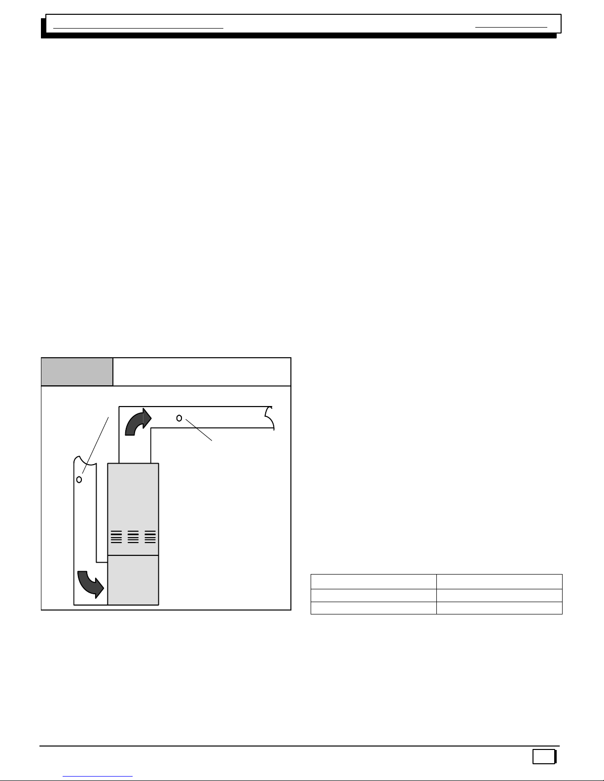
L.P. PRESSURE SWITCH
Models equipped for or converted to operate on LP Gas will
be equipped with an LP Pressure Switch. If so equipped,
the switch will be located in the gas supply line (in a “Tee”
fitting), just ahead of the gas valve.
The purpose of this switch is to prevent furnace operating
under low line (Supply) pressure conditions. Operating under low line pressure conditions, can create problems such
as incomplete combustion, flashback, sooting, etc.
The switch is a “Normally Open” pressure operated switch
that is wired in series with the furnace (air proving) pressure
switch. The L.P. Pressure Switch closes when line (Supply)
pressure is 8.0″ W.C. or higher. the L.P. Pressure Switch
Opens if line pressure falls below 6.0″+ 0.6″ W.C. interrupting power to the gas valve.
Figure 8
Typical L.P. Pressure Switch
12
440 08 2011 00
Single Stage Multi Position Furnace
HONEYWELL VR8205S Gas Valve
Service Manual
The VR8205S Gas Valve is a REDUNDANT type valve.
This means that it consists of two (2) valves (internally) with
independent operators (solenoids) that both must be energized before gas can flow through the valve. This redundancy provides an added safety measure. In case one of the
valves sticks open (Mechanically), the second operator will
close preventing the flow of gas.
If the valve does not open, check for 24 Volts across the two
HIGH ALTITUDE OPERATION
These furnaces are designed to operate in the majority of
the country without modifications. At altitudes over 2,000′
above sea level, however, certain measures need to be taken to insure continued, safe reliable operation. For example, units must be de−rated for altitude (by adjusting manifold pressure and/or changing orifice size) based upon the
type of fuel (I.E. Natural Gas or L.P. gas), Btu content of the
gas, and installed altitude.
Altitudes over 4,000′ may require a different air proving
pressure switch than the one installed at the factory. Check
CHECKING TEMPERATURE RISE
Figure 9
Thermometer:
Return Air Temp.
Return
Checking Temperature Rise
Supply
Air Flow
Thermometer;
Supply Air Temp.
wires to the valve during a call for heat. This check MUST
be made IMMEDIATELY following the igniter warm−up peri-
od (17 seconds). 24 Volts will be present ONLY for a period
of 7 seconds after the igniter warm−up if flame is not proven.
If 24 Volts is present during the above check and the valve
will NOT open, then replace the valve. If 24 Volts IS NOT
present, problems are indicated in the control and/or wiring
to the gas valve.
parts list for pressure switch and consult your distributor for
part number and availability. In Canada, provincial codes
may govern installation or switch. Check with governing authorities.
When servicing a unit installed at altitudes above 2,000′ insure that it has been properly modified to operate at that altitude. See the sections on Gas pressure (Page 10), and
pressure switches (Page 15) to obtain specific information
for you particular installation altitude.
To check temperature rise,use the following procedure:
1. Place thermometers in supply and return air registers
as close to furnace as possible, avoiding direct radiant heat from heat exchangers.
2. Operate furnace continuously for 15 minutes with all
registers and duct dampers open.
3. Take reading and compare with range specified on
rating plate.
4. If the correct amount of temperature rise is NOT ob-
tained, it may be necessary to change blower speed.
A higher blower speed will lower the temperature rise.
A lower blower speed will increase the temperature
rise.
NOTE: BEFORE CHECKING TEMPERATURE RISE BE
CERTAIN THAT MANIFOLD PRESSURE IS PROPERLY
ADJUSTED.
Air Flow
Temperature Rise Check
The blower speed MUST be set to give the correct air temperature rise through the furnace as marked on the rating
plate. Temperature rise is the difference between supply
and return air temperatures.
440 08 2011 00
ALLOWABLE TEMPERATURE RISE ALL MODELS
Model
50, 80 Mbtu 35°F − 65°F
75, 100 & 125 Mbtu 40°F − 70°F
Example:
Supply Temp. 170°
Return Temp. 70°
Temperature Rise 100° = Too High
Solution: Increase Blower Speed
Range
13
 Loading...