

International comfort products N2A4 Series, H2A3 Series, T2A3 Series, C2A3 Series, N4A3 Series Installation Instructions Manual
...
INSTALLATION INSTRUCTIONS
R-22 Split System Air Conditioner
Product Family: N2A3, C2A3, H2A3, T2A3, N2A4
These instructions must be read and understood completely before attempting installation.
Safety Labeling and Signal Words
DANGER, WARNING, CAUTION, and
NOTE
The signal words DANGER, WARNING,
CAUTION, and NOTE are used to identify levels of
hazard seriousness. The signal word DANGER is
only used on product labels to signify an immediate
hazard. The signal words WARNING, CAUTION,
and NOTE will be used on product labels and
throughout this manual and other manuals that may
apply to the product.
DANGER - Immediate hazards which will result in
severe personal injury or death.
WARNING - Hazards or unsafe practices which
could result in severe personal injury or death.
CAUTION - Hazards or unsafe practices which
may result in minor personal injury or product or
property damage.
NOTE - Used to highlight suggestions which will
result in enhanced installation, reliability, or operation.
Signal Words in Manuals
The signal word WARNING is used throughout this
manual in the following manner:
WARNING
!
The signal word CAUTION is used throughout this
manual in the following manner:
!
Signal Words on Product Labeling
Signal words are used in combination with colors
and/or pictures on product labels.
WARNING
CAUTION
TABLE OF CONTENTS
Inspect New Unit 2. . . . . . . . . . . . . . . . . . . . . . . . . . . . . . .
Safety Considerations 2. . . . . . . . . . . . . . . . . . . . . . . . . . .
Location 2. . . . . . . . . . . . . . . . . . . . . . . . . . . . . . . . . . . . . . .
Clearances 2 - 3. . . . . . . . . . . . . . . . . . . . . . . . . . . . . . . . .
Unit Support 4. . . . . . . . . . . . . . . . . . . . . . . . . . . . . . . . . . .
Refrigeration System 5 - 8. . . . . . . . . . . . . . . . . . . . . . . .
Electrical Wiring 9 - 10. . . . . . . . . . . . . . . . . . . . . . . . . . . .
Start-up Procedure 11. . . . . . . . . . . . . . . . . . . . . . . . . . . .
Refrigerant Charge 11. . . . . . . . . . . . . . . . . . . . . . . . . . . .
Sequence of Operation 11. . . . . . . . . . . . . . . . . . . . . . . . .
Troubleshooting 12. . . . . . . . . . . . . . . . . . . . . . . . . . . . . . .
Maintenance 12. . . . . . . . . . . . . . . . . . . . . . . . . . . . . . . . . .
Comfort Alertt Diagnostics Codes 13. . . . . . . . . . . . . .
!
DEATH, PERSONAL INJURY, AND/OR PROPERTY
DAMAGE HAZARD
Failure to carefully read and follow this warning
could result in equipment malfunction, property
damage, personal injury and/or death.
Installation or repairs made by unqualified per‐
sons could result in equipment malfunction, prop‐
erty damage, personal injury and/or death.
The information contained in this manual is in‐
tended for use by a qualified service technician fa‐
miliar with safety procedures and equipped with
the proper tools and test instruments.
Installation must conform with local building
codes and with the National Electrical Code
NFPA70 current edition or Canadian Electrical
Code Part 1 CSA C.22.1.
WARNING
421 01 5001 00 March 2008
INSTALLATION INSTRUCTIONS R-22 Split System Air Conditioner
INSPECT NEW UNIT
After uncrating unit, inspect thoroughly for hidden
damage. If damage is found, notify the transportation
SAFETY CONSIDERATIONS
Consult a qualified installer, service agency, or the
dealer/distributor for information and assistance. The
qualified installer must use factory authorized kits and
accessories when modifying this product. Refer to the
individual instructions packaged with the kit or accessory
when installing.
The weight of the product requires careful and proper
handling procedures when lifting or moving to avoid
personal injury. Use care to avoid contact with sharp or
pointed edges.
Follow all safety codes. Wear safety glasses, protective
clothing, and work gloves. Use a heat sinking material such as a wet rag - during brazing operations. Keep a fire
extinguisher available. Consult local codes and the
National Electric Code (NEC) for special requirements.
Improper installation, adjustment, alteration, service or
maintenance can void the warranty.
LOCATION
Check local codes for regulations concerning zoning,
noise, platforms, and other issues.
Locate unit away from fresh air intakes, vents, or
bedroom windows. Noise may carry into the openings
and disturb people inside.
Locate unit in a well drained area, or support unit high
enough so that water runoff will not enter the unit.
Locate unit away from areas where heat, lint, or exhaust
fumes will be discharged onto unit (as from dryer vents).
company immediately and file a concealed damage
claim.
!
ELECTRICAL SHOCK HAZARD
Failure to turn off the main (remote) electrical dis‐
connect device could result in personal injury or
death.
Before installing, modifying or servicing system,
turn OFF the main (remote) electrical disconnect
device. There may be more than one disconnect
device.
Locate unit away from recessed or confined areas where
recirculation of discharge air may occur (refer to
CLEARANCES section of this document).
Roof-top installation is acceptable providing the roof will
support the unit and provisions are made for water
drainage and noise/vibration dampening.
NOTE: Roof mounted units exposed to wind may require
wind baffles. Consult the manufacturer for additional
information.
WARNING
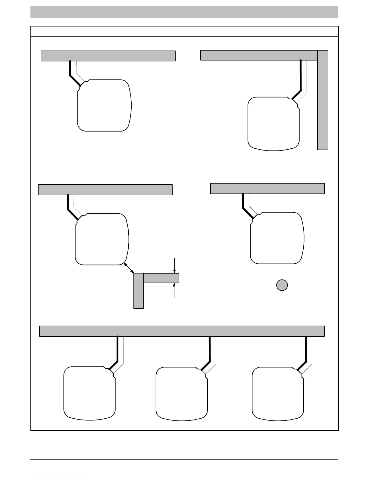
CLEARANCES
Nominal minimum clearances are 48 inches above unit
for discharge air and 18 inches on each side of the coil for
intake air. Clearance on any one side of the coil (normally
between unit and structure) may be reduced to 6 inches.
Nominal minimum clearances are based on a solid
parallel object such as a wall or roof overhang.
The clearance may be reduced for a single object with
small surface area, such as the end of a wall, outside
corner of a wall, fence section, post, etc. As a general
rule, the minimum clearance from the unit should equal
the width of the object. For example, a 6 inch fence post
should be a minimum of 6 inches from the unit.
Do not install unit under roof overhangs unless gutters are
present. A minimum vertical clearance of 48 inches is
required to the overhang.
Inside corner locations on single story structures require
evaluation. Large overhanging soffits may cause air
recirculation in a corner area even though recommended
minimum clearances are maintained. As a guide, locate
the unit far enough out so that half of the discharge grille is
out from under the soffit.
When placing two or more units side-by-side, provide a
minimum of 18 inches between units.
Provide minimum service clearance of 24 inches from
control box corner and side service panel.
Refer to Figure 1.
2 421 01 5001 00
INSTALLATION INSTRUCTIONS R-22 Split System Air Conditioner
Figure 1 Clearances (various examples)
24”
Service
Wall
6”
18”
Wall
6”
18”
18”
Wall
24”
Service
Wall
6”
18”
Wall
6”
24”
Service
18”
24”
Service
4”
18”
18”
4”
wide fence
Wall
24”
Service
24”
Service
18”
18”
6”
6”
Post
24”
Service
18”
421 01 5001 00 3
INSTALLATION INSTRUCTIONS R-22 Split System Air Conditioner
UNIT SUPPORT
NOTE: Unit must be level 2 degrees ( inch rise or fall
per foot of run) or compressor may not function properly.
A. GROUND LEVEL INSTALLATION
The unit must be level and supported above grade by
beams, platform, or a pad. Platform or pad can be of open
or solid construction but should be of permanent
materials such as concrete, bricks, blocks, steel, or
pressure- treated timbers approved for ground contact.
Soil conditions must be considered so that the platform or
pad does not shift or settle and leave the unit partially
supported. Minimum pad dimensions are shown in Figure
2.
If beams or an open platform are used for support, it is
recommended that the soil be treated or area be graveled
to reduce the growth of grasses and weeds.
To minimize vibration or noise transmission, it is
recommended that supports not be in contact with the
building structure. However, slabs on grade constructions
with an extended pad are normally acceptable.
B. ROOF TOP INSTALLATION
This type of installation is not recommended on wood
frame structures where low noise levels are required.
Supporting structure or platform for the unit must be level.
If installation is on a flat roof, locate unit minimum 6 inches
above roof level.
Place the unit over one or more load bearing walls. If there
are several units, mount them on platforms that are
self-supporting and span several load bearing walls.
These suggestions are to minimize noise and vibration
transmission through the structure. If the structure is a
home or apartment, avoid locating the unit over
bedrooms or study.
NOTE: When unit is to be installed on a bonded
guaranteed roof, a release must be obtained from the
building owner to free the installer from all liabilities.
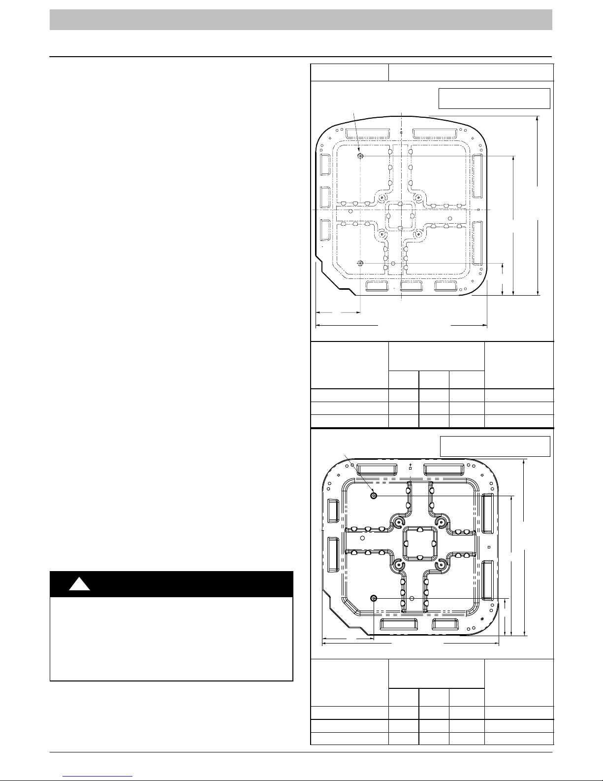
C. FASTENING UNIT DOWN
If conditions or local codes require the unit be attached in
place, remove the knockouts in the base pan and install
tie down bolts through the holes (refer to Figure 2).
Contact local distributor for hurricane hold-down details
and the P.E. (Professional Engineer) certification, when
required.
Figure 2 Tie Down Knockouts
” dia. Tie Down Knockouts
In Base Pan (2 places)
A
Base Pan Width
Base Pan
(Bumpout)
Width x Depth
(inches)
A B C
Tie Down
Knockouts
View From Top
Product Family: C,H,T series
C
B
Minimum
Mounting Pad
Dimensions
” dia. Tie Down Knockouts
In Base Pan (2 places)
View From Top
Product Family: N series
C
Base
Pan
Depth
Base
Pan
Depth
!
CAUTION
PROPERTY DAMAGE HAZARD
Failure to follow this caution may result in proper‐
ty damage.
Inadequate unit support may cause excessive
vibration, noise, and/or stress on the refrigerant
lines, leading to refrigerant line failure.
4 421 01 5001 00
B
A
Base Pan
(Square)
Width x Depth
(inches)
Base Pan Width
Tie Down
Knockouts
A B C
Minimum
Mounting Pad
Dimensions
 Loading...