

International comfort products H2A336G D200 series, H2A342G D200 series, H2A348G D200, series, H2A360G D300 series Technical Support Manual
TECHNICAL SUPPORT MANUAL
Split System Air Conditioner
H2A3, 3−Phase
Safety Labeling and Signal Words
DANGER, WARNING, CAUTION, and
NOTE
The signal words DANGER, WARNING, CAUTION, and NOTE are used to identify levels of haz-
ard seriousness. The signal word DANGER is only
used on product labels to signify an immediate hazard. The signal words WARNING, CAUTION, and
NOTE will be used on product labels and throughout this manual and other manuals that may apply
to the product.
DANGER − Immediate hazards which will result in
severe personal injury or death.
WARNING − Hazards or unsafe practices which
could result in severe personal injury or death.
CAUTION − Hazards or unsafe practices which
may result in minor personal injury or product or
property damage.
NOTE − Used to highlight suggestions which will
result in enhanced installation, reliability, or operation.
Signal Words in Manuals
The signal word WARNING is used throughout this
manual in the following manner:
!
The signal word CAUTION is used throughout this
manual in the following manner:
!
Signal Words on Product Labeling
Signal words are used in combination with colors
and/or pictures on product labels.
WARNING
WARNING
CAUTION
TABLE OF CONTENTS
Wiring Diagram 2. . . . . . . . . . . . . . . . . . . . . . . . . . . . . . . .
Charging Chart 3. . . . . . . . . . . . . . . . . . . . . . . . . . . . . . . . .
Tech Labels (Expanded Data) 4 − 7. . . . . . . . . . . . . . . . .
Condenser Only Data 8 − 9. . . . . . . . . . . . . . . . . . . . . . . .
Cooling Multipying Factors 10 − 13. . . . . . . . . . . . . . . . . .
Model Number Identification 14. . . . . . . . . . . . . . . . . . . .
MODELS
H2A336G*D200
H2A342G*D200
H2A348G*D200
H2A360G*D300
* = H or L
!
DEATH, PERSONAL INJURY, AND/OR PROPERTY
DAMAGE HAZARD
Failure to carefully read and follow this warning
could result in equipment malfunction, property
damage, personal injury and/or death.
Installation or repairs made by unqualified persons could result in equipment malfunction, property damage, personal injury and/or death.
The information contained in this manual is intended for use by a qualified service technician familiar with safety procedures and equipped with
the proper tools and test instruments.
Installation must conform with local building
codes and with the National Electrical Code
NFPA70 current edition or Canadian Electrical
Code Part 1 CSA C.22.1.
WARNING
501 04 2502 00 Aug 2009
TECHNICAL SUPPORT MANUAL Split System Air Conditioner: H2A3, 3−Phase
2 501 04 2502 00
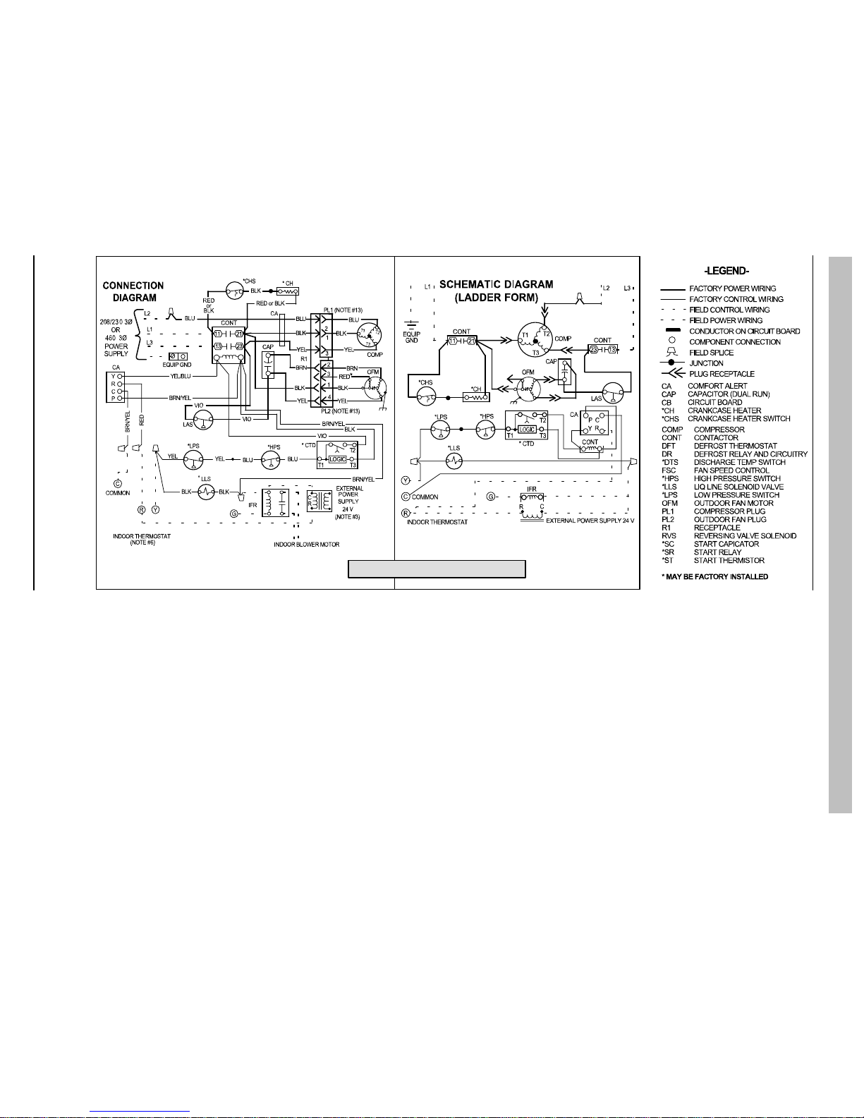
Model Sizes: 36, 42, 48, 60
334996−101_A
1. Symbols are electrical representation only.
2. Compressor and fan motor furnished with inherent thermal protection.
3. To be wired in accordance with National Electric N.E.C. and local codes.
4. N.E.C. class 2, 24 V circuit, min. 40 VA required, 60 VA on units installed with LLS.
5. Use copper conductors only. Use conductors suitable for at least 75°C (167°F).
6. Connection for typical cooling only thermostat. For other arrangements see installation instructions.
7. If indoor section has a transformer with a grounded secondary, connect the grounded side to the BRN/YEL lead.
8. When start capacitor and relay are installed, start thermistor is not used.
9. CH not used on all units.
10. If any of the original wire, as supplied, must be replaced, use the same or equivalent wire.
11. Check all electrical connections inside control box for tightness.
12. Do not attempt to operate unit until service valves have been opened.
13. Do not rapid cycle compressor. Compressor must be off 3 minutes to allow pressures to equalize between high and low side before starting.
14. It is imperative to connect 3−phase field power to unit with correct phasing. If phasing is reversed, interchange any two of the three power connections on field side.
15. Wire not present if HPS, LPS or CTD are used.
16. Not for interrupting current.
TECHNICAL SUPPORT MANUAL Split System Air Conditioner: H2A3, 3−Phase
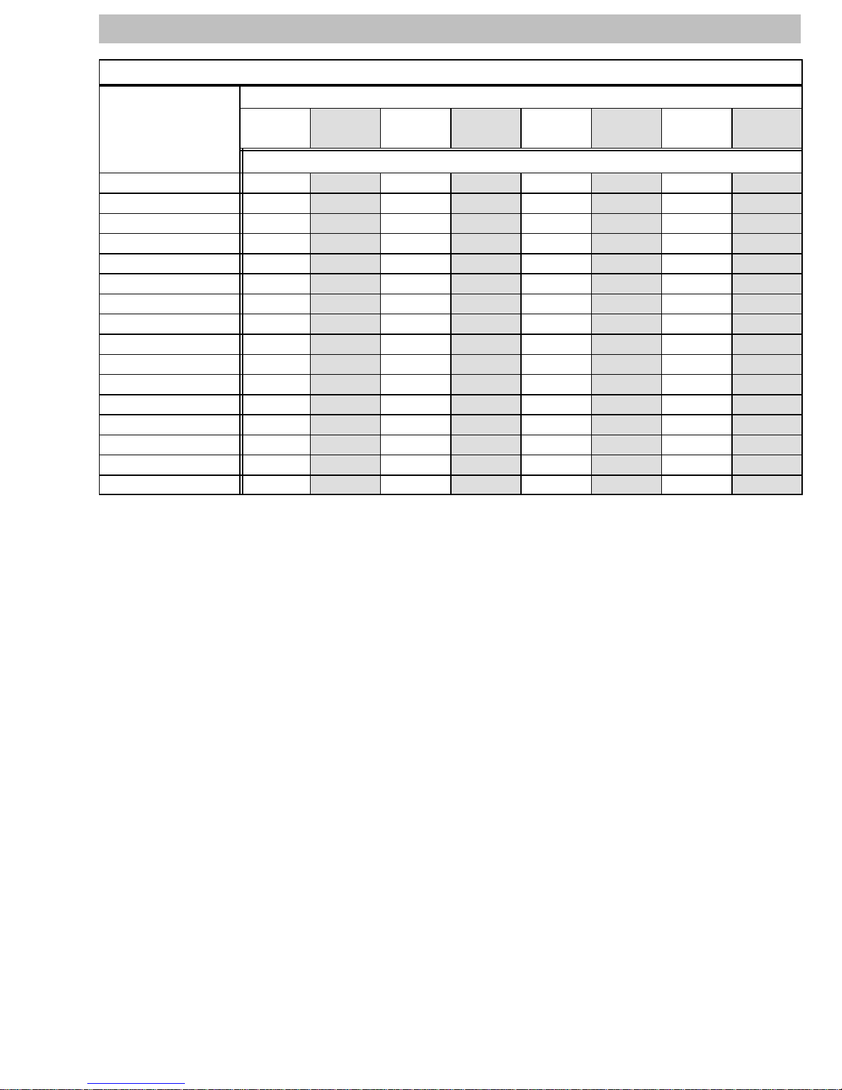
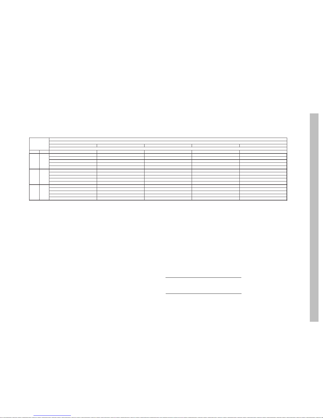
R−22 CHARGING CHART
Rating Plate (required) Subcooling Temperature ° F (° C)
Measured Liquid
Pressure (psig)
163 83 28 78 26 73 23 68 20
171 86 30 81 27 76 24 71 22
179 89 32 84 29 79 26 74 23
187 92 33 87 31 82 28 77 25
196 95 35 90 32 85 29 80 27
205 98 37 93 34 88 31 83 28
214 101 38 96 36 91 33 86 30
223 104 40 99 37 94 34 89 32
233 107 42 102 39 97 36 92 33
243 110 43 105 41 100 38 95 35
253 113 45 108 42 103 39 98 37
264 116 47 111 44 106 41 101 38
274 119 48 114 46 109 43 104 40
285 122 50 117 47 112 44 107 42
297 125 52 120 49 115 46 110 43
309 128 53 123 51 118 48 113 45
° F (° C) ° F (° C) ° F (° C) ° F (° C)
5 3 10 6 15 8 20 11
R−22 Required Liquid Line Temperature ° F (° C)
501 04 2502 00 3
TECHNICAL SUPPORT MANUAL Split System Air Conditioner: H2A3, 3−Phase
4 501 04 2502 00
CFM 72 67 63†† 62 57 72 67 63†† 62 57 72 67 63†† 62 57 72 67 63†† 62 57 72 67 63†† 62 57
MBh†
39.31 35.87 33.37 32.92 32.17 37.99 34.65 32.22 31.82 31.27 36.55 33.31 30.95 30.63 30.27 34.98 31.84 29.55 29.32 29.15 33.27 30.24 28.01 27.93 27.91
S/T‡
0.52 0.70 0.72 0.90 1.00 0.52 0.71 0.74 0.92 1.00 0.53 0.72 0.75 0.93 1.00 0.54 0.73 0.76 0.95 1.00 0.54 0.75 0.78 0.99 1.00
*AMPS
11.56 11.44 11.30 11.28 11.23 12.51 12.40 12.26 12.24 12.21 13.59 13.48 13.35 13.33 13.31 14.83 14.74 14.61 14.60 14.59 16.29 16.21 16.09 16.09 16.09
HI PR
164 162 161 161 160 194 191 189 189 189 226 223 221 220 220 260 257 254 254 254 297 294 291 291 291
LO PR
86 78 72 71 69 87 79 73 72 71 89 80 74 74 73 90 82 76 75 75 92 83 77 77 77
MBh†
39.89 36.44 33.93 33.69 33.42 38.52 35.18 32.75 32.58 32.46 37.03 33.80 31.44 31.35 31.40 35.42 32.30 30.00 30.22 30.22 33.66 30.65 28.42 28.91 28.92
S/T‡
0.53 0.73 0.76 0.94 1.00 0.54 0.74 0.77 0.96 1.00 0.55 0.75 0.78 1.00 1.00 0.55 0.77 0.80 1.00 1.00 0.57 0.79 0.82 1.00 1.00
*AMPS
11.82 11.72 11.59 11.58 11.56 12.76 12.67 12.55 12.54 12.54 13.84 13.75 13.63 13.63 13.64 15.08 15.01 14.89 14.91 14.91 16.53 16.48 16.37 16.40 16.40
HI PR
165 163 161 161 161 194 192 190 190 190 226 223 221 221 221 261 258 255 256 256 298 295 292 293 293
LO PR
88 80 74 73 73 89 81 75 75 74 91 82 76 76 76 92 84 77 78 78 93 85 79 80 80
MBh†
40.31 36.89 34.38 34.40 34.45 38.90 35.58 33.16 33.43 33.43 37.37 34.17 31.82 32.31 32.32 35.72 32.63 30.35 31.08 31.08 33.92 30.95 28.74 29.72 29.72
S/T‡
0.55 0.76 0.79 1.00 1.00 0.56 0.77 0.80 1.00 1.00 0.56 0.79 0.81 1.00 1.00 0.57 0.81 0.83 1.00 1.00 0.59 0.83 0.86 1.00 1.00
*AMPS
12.07 11.99 11.87 11.87 11.88 13.01 12.94 12.83 12.85 12.85 14.08 14.02 13.91 13.94 13.94 15.32 15.27 15.17 15.21 15.21 16.77 16.74 16.64 16.69 16.69
HI PR
165 163 162 162 162 195 192 190 191 191 227 224 222 222 222 261 258 256 257 257 299 295 292 294 294
LO PR
90 82 75 76 76 91 83 76 77 77 92 84 77 79 79 93 85 79 81 81 95 86 80 83 83
1050
COOLING
36 Size Outdoor With EB*2X36F** Indoor Cooling
Outdoor Ambient Temperature − Degrees F, Dry Bulb
75
Entering Indoor Temperature − Degrees F, Wet Bulb
5115015958
1200
1350
† Total capacities are net (I.D. blower heat subtracted) system capacities based on 25’ line set.
If additional tubing length and/or indoor unit is located above outdoor unit, a slight variation in capacity may occur.
†† At TVA rating indoor condition (75 °F db, 63 °F wb), all other indoor air temperatures are at 80 ° F db
If additional tubing length and/or indoor unit is located above outdoor unit, a slight variation in capacity may occur.
^ System amps are total of indoor and outdoor amps.
‡ Chart data is for 80° F indoor dry bulb. For indoor db temperatures other than 80° F, measure Indoor db and Indoor CFM, and plug these into the
formula below. Measure outdoor db and indoor wet bulb, apply these to the chart above, find MBh and S/T, and plug these into the formula below.
(Note: if indoor db is the only thing changing, total capacity, MBh, stays the same.)
Sensible Capacity at Indoor db LOWER than 80 ° F = ( MBh x S/T ) −
( 80 − Indoor db ) x 835 x Indoor CFM
1000
(
)
Sensible Capacity at Indoor db HIGHER than 80 °F = ( MBh x S/T ) +
( Indoor db − 80 ) x 835 x Indoor CFM
1000
(
)
TECHNICAL SUPPORT MANUAL Split System Air Conditioner: H2A3, 3−Phase
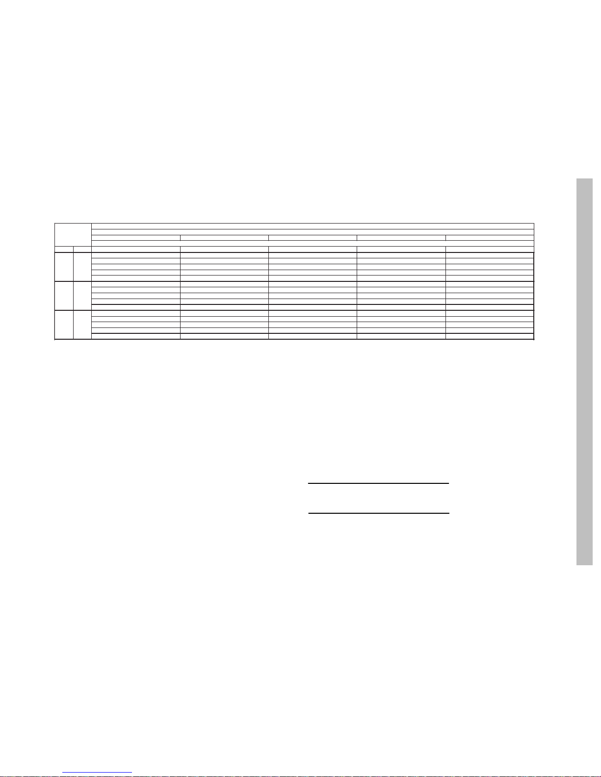
501 04 2502 00 5
CFM 72 67 63†† 62 57 72 67 63†† 62 57 72 67 63†† 62 57 72 67 63†† 62 57 72 67 63†† 62 57
MBh†
47.43 43.05 39.93 39.38 38.53 45.76 41.50 38.48 38.01 37.39 44.00 39.88 36.96 36.58 36.20 42.17 38.19 35.37 35.10 34.93 40.25 36.42 33.71 33.54 33.60
S/T‡
0.53 0.71 0.74 0.92 1.00 0.53 0.73 0.75 0.94 1.00 0.54 0.74 0.77 0.96 1.00 0.55 0.75 0.78 0.98 1.00 0.56 0.77 0.80 1.00 1.00
*AMPS
12.93 12.80 12.70 12.69 12.67 14.28 14.14 14.05 14.03 14.01 15.79 15.64 15.53 15.52 15.51 17.45 17.29 17.17 17.16 17.15 19.26 19.08 18.94 18.94 18.94
HI PR
166 165 163 163 163 196 194 192 192 192 228 226 224 223 223 264 260 258 258 258 302 298 295 295 295
LO PR
85 77 71 70 69 86 78 72 71 70 87 79 73 73 72 89 81 75 74 74 90 82 76 76 76
MBh†
48.20 43.77 40.62 40.32 40.04 46.45 42.17 39.12 38.94 38.83 44.63 40.50 37.55 37.49 37.56 42.73 38.76 35.92 36.22 36.22 40.74 36.94 34.20 34.80 34.80
S/T‡
0.54 0.75 0.77 0.97 1.00 0.55 0.76 0.79 0.98 1.00 0.56 0.77 0.80 1.00 1.00 0.57 0.79 0.82 1.00 1.00 0.58 0.81 0.84 1.00 1.00
*AMPS
13.25 13.11 13.01 13.01 13.00 14.59 14.46 14.36 14.35 14.35 16.10 15.95 15.84 15.85 15.85 17.76 17.60 17.48 17.50 17.50 19.57 19.40 19.26 19.30 19.30
HI PR
167 165 164 164 164 197 194 193 193 193 229 226 224 224 224 264 261 259 259 259 302 299 296 297 297
LO PR
87 79 73 72 72 88 80 74 74 74 89 81 75 75 75 90 82 76 77 77 92 84 78 79 79
MBh†
48.78 44.37 41.19 41.24 41.30 46.97 42.72 39.65 40.02 40.02 45.10 41.00 38.03 38.68 38.68 43.15 39.21 36.35 37.27 37.27 41.10 37.34 34.60 35.78 35.79
S/T‡
0.56 0.78 0.81 1.00 1.00 0.57 0.79 0.82 1.00 1.00 0.58 0.81 0.84 1.00 1.00 0.59 0.83 0.86 1.00 1.00 0.60 0.85 0.88 1.00 1.00
*AMPS
13.55 13.42 13.32 13.32 13.33 14.90 14.76 14.66 14.68 14.68 16.41 16.26 16.15 16.18 16.18 18.07 17.91 17.79 17.83 17.83 19.88 19.71 19.58 19.64 19.64
HI PR
167 165 164 164 164 197 195 193 193 193 229 227 225 225 225 265 262 259 260 260 303 299 297 298 298
LO PR
88 80 74 75 75 89 81 75 76 76 91 83 77 78 78 92 84 78 80 80 93 85 79 82 82
511501
Entering Indoor Temperature − Degrees F, Wet Bulb
1225
1400
1575
COOLING
42 Size Outdoor With ED*4X42J** Indoor Cooling
Outdoor Ambient Temperature − Degrees F, Dry Bulb
595857
† Total capacities are net (I.D. blower heat subtracted) system capacities based on 25’ line set.
If additional tubing length and/or indoor unit is located above outdoor unit, a slight variation in capacity may occur.
†† At TVA rating indoor condition (75 °F db, 63 °F wb), all other indoor air temperatures are at 80 ° F db
If additional tubing length and/or indoor unit is located above outdoor unit, a slight variation in capacity may occur.
^ System amps are total of indoor and outdoor amps.
‡ Chart data is for 80° F indoor dry bulb. For indoor db temperatures other than 80° F, measure Indoor db and Indoor CFM, and plug these into the
formula below. Measure outdoor db and indoor wet bulb, apply these to the chart above, find MBh and S/T, and plug these into the formula below.
(Note: if indoor db is the only thing changing, total capacity, MBh, stays the same.)
Sensible Capacity at Indoor db LOWER than 80 ° F = ( MBh x S/T ) −
( 80 − Indoor db ) x 835 x Indoor CFM
1000
(
)
Sensible Capacity at Indoor db HIGHER than 80 °F = ( MBh x S/T ) +
( Indoor db − 80 ) x 835 x Indoor CFM
1000
(
)
 Loading...