

International comfort products G9MXT0401410A, G9MXT1002116A, G9MXT0601714A, G9MXT0801716A, G9MXT1202422A Service And Technical Support Manual
...
SERVICE AND TECHNICAL
SUPPORT MANUAL
TwoStage, ECM Blower Motor
35” Tall, High Efficiency Condensing Gas Furnace
(F/G)9MXT
Save this manual for future reference.
Safety Labeling and Signal Words
DANGER, WARNING, CAUTION, and NOTE
The signal words DANGER, WARNING,
CAUTION, and NOTE are used to identify levels of
hazard seriousness. The signal word DANGER is
only used on product labels to signify an immediate
hazard. The signal words WARNING, CAUTION,
and NOTE will be used on product labels and
throughout this manual and other manual that may
apply to the product.
DANGER Immediate hazards which will result in
severe personal injury or death.
WARNING Hazards or unsafe practices which
could result in severe personal injury or death.
CAUTION Hazards or unsafe practices which
may result in minor personal injury or product or
property damage.
NOTE Used to highlight suggestions which will
result in enhanced installation, reliability, or
operation.
Signal Words in Manuals
The signal word WARNING is used throughout
this manual in the following manner:
!
WARNING
The signal word CAUTION is used throughout
this manual in the following manner:
!
CAUTION
Signal Words on Product Labeling
Signal words are used in combination with
colors and/or pictures or product labels.
Safetyalert symbol
When you see this symbol on the unit and in
instructions or manuals, be alert to the
potential for personal injury.
TABLE OF CONTENTS
STARTUP, ADJUSTMENT, AND SAFETY CHECK 4...........
THERMOSTAT SETUP SWITCH 4...........................
PRIME CONDENSATE TRAP WITH WATER 4.................
PURGE GAS LINES 4......................................
ADJUSTMENTS 5.........................................
ADJUST TEMPERATURE RISE 9............................
ADJUST BLOWER OFF DELAY (HEAT MODE) 9..............
ADJUST COOLING AIRFLOW 9.............................
ADJUST CONTINUOUS FAN AIRFLOW 10....................
ADJUST THERMOSTAT HEAT ANTICIPATOR 10...............
CHECK SAFETY CONTROLS 10.............................
CHECKLIST 10.............................................
SERVICE AND MAINTENANCE PROCEDURES 12.............
ELECTRICAL CONTROLS AND WIRING 12...................
TROUBLESHOOTING 12....................................
CLEANING AND/OR REPLACING AIR FILTER 14..............
BLOWER MOTOR AND WHEEL MAINTENANCE 14............
CLEANING BURNERS AND FLAME SENSOR 16...............
SERVICING HOT SURFACE IGNITER 17......................
FLUSHING COLLECTOR BOX AND DRAINAGE SYSTEM 17....
CLEANING CONDENSATE DRAIN AND TRAP 18..............
CLEANING HEAT EXCHANGERS 18..........................
SERVICE LABEL 20.........................................
WIRING DIAGRAM 21.......................................
SEQUENCE OF OPERATION 24.............................
PARTS REPLACEMENT INFORMATION GUIDE 28.............
PRODUCT NOMENCLATURE 29.............................
MODELS
(F/G)9MXT0401410A
(F/G)9MXT0601714A
(F/G)9MXT0801716A
(F/G)9MXT1002116A
(F/G)9MXT1202422A
Use of the AHRI Certified TM Mark indicates a
manufacturer’s participation in the program.
For verification of certification for individual
products, go to www.ahridirectory.org .
Printed in U.S.A. 440 04 4321 02 Aug. 2011
SAFETY CONSIDERATIONS
Improper installation, adjustment, alteration, service,
maintenance, or use can cause explosion, fire, electrical shock,
or other conditions which may cause death, personal injury, or
property damage. Consult a qualified installer, service agency,
or your distributor or branch for information or assistance. The
qualified installer or agency must use factoryauthorized kits or
accessories when modifying this product. Refer to the individual
instructions packaged with the kits or accessories when
installing.
Follow all safety codes. Wear safety glasses, protective clothing,
and work gloves. Use quenching cloth for brazing operations.
Have fire extinguisher available. Read these instructions
thoroughly and follow all warnings or cautions included in
literature and attached to the unit. Consult local building codes,
the current editions of the National Fuel Gas Code (NFCG)
NFPA 54/ANSI Z223.1, and the National Electrical Code (NEC)
NFPA 70.
In Canada refer to the current editions of the National standards
of Canada CAN/CSAB149.1 and .2 Natural Gas and Propane
Installation Codes, and Canadian Electrical Code CSA C22.1.
Recognize safety information. This is the safetyalert symbol
. When you see this symbol on the unit and in instructions or
manuals, be alert to the potential for personal injury.
Understand these signal words; DANGER, WARNING, and
CAUTION. These words are used with the safetyalert symbol.
DANGER identifies the most serious hazards which will result in
severe personal injury or death. WARNING signifies hazards
which could result in personal injury or death. CAUTION is used
to identify unsafe practices which may result in minor personal
injury or product and property damage. NOTE is used to
highlight suggestions which will result in enhanced installation,
reliability, or operation.
!
WARNING
PERSONAL INJURY, AND/OR PROPERTY
DAMAGE HAZARD
Failure to carefully read and follow this warning could
result in equipment malfunction, property damage,
personal injury and/or death.
Installation or repairs made by unqualified persons could
result in equipment malfunction, property damage,
personal injury and/or death.
The information contained in this manual is intended for
use by a qualified service technician familiar with safety
procedures and equipped with proper tools and test
instruments.
Installation must conform with local building codes and
with the Natural Fuel Gas Code (NFCG) NFPA 54/ANSI
Z223.1, and National standards of Canada
CAN/CSAB149.1 and .2 Natural Gas and Propane
Installation Codes.
!
ELECTRICAL SHOCK HAZARD
Failure to follow this warning could cause personal
injury or death.
Before performing service or maintenance operations
on unit, always turn off main power switch to unit and
install lockout tag. Unit may have more than one power
switch.
!
WARNING
WARNING
CARBON MONOXIDE POISONING AND FIRE
HAZARD
Failure to follow safety warnings could result in personal
injury, death, and/or property damage.
This furnace is not designed for use in mobile homes,
trailers or recreational vehicles.
!
CAUTION
CUT HAZARD
Failure to follow this caution may result in damage
personal injury.
Sheet metal parts may have sharp edges or burrs. Use
care and wear appropriate protective clothing, safety
glasses and gloves when handling parts and servicing
furnaces.
2
Specifications are subject to change without notice.
440 04 4321 02
SERVICE AND TECHNICAL MANUAL Gas Furnace: (F/G)9MXT
STARTUP CHECK SHEET
For PSC Models (F/G)9MXT
(This sheet is optional. Keep for future reference.)
Date of StartUp:
Dealer Name:
Address:
City, State(Province), Zip or Postal Code:
Phone:
Owner Name:
Address:
City, State(Province), Zip or Postal Code:
Model Number:
Serial Number:
Setup Checks
Check the box when task is complete.
All Electrical Connections Tight?
Have hoses been relocated for furnace U/D/H application?
Calculated Input (BTU) Rate: (See Checks and Adjustments
Section).
Heating Check
Measured Line Pressure During High Heat:
Measured Manifold Pressure: High Heat
Low Heat
Temperature of Supply Air: High Heat
Low Heat
Temperature of Return Air:
Temperature Rise (Supply Return): High Heat
Low Heat
In Rise Range (see furnace rating plate)?
Static Pressure (Ducts) High Heat: Supply
Return
The Blower Speed Tap used for: High Heat
Low Heat
Optional Check: CO?
CO2?
Cooling Check
Condensate Drain Connected?
Condensate Drain Trapped?
Manual Gas Shutoff Upstream of Furnace/Drip Leg
Gas Valve turned ON?
Type of Gas: Natural: Propane:
Filter Type and Size:
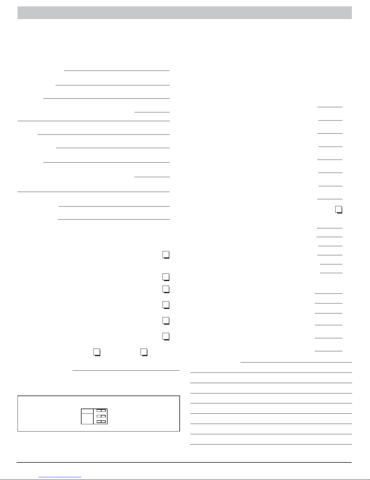
Shade in Heating Fan “Time OFF” Setting and Thermostat
Type setting:
OFF
ON
TT
OFF
DLY
1 2 3
Temperature of Supply Air:
Temperature of Return Air:
Temperature Difference:
Static Pressure (Ducts) Cooling: Supply
Return
The Blower Speed Tap used for: Cooling
Dealer Comments:
440 04 4321 02 3
Specifications subject to change without notice.
SERVICE AND TECHNICAL SUPPORT MANUAL Gas Furnace: (F/G)9MXT
STARTUP, ADJUSTMENT, AND SAFETY
CHECK
General
1. Furnace must have a 115-V power supply properly
connected and grounded.
NOTE: Proper polarity must be maintained for 115-V wiring.
Control status indicator light flashes code 10 and furnace does
not operate if polarity is incorrect.
2. Thermostat wire connections at terminals R, W/W1, G,
and Y/Y2 must be made at 24-V terminal block on
furnace control.
3. Natural gas service pressure must not exceed 0.5 psig
(14- in. w.c.), but must be no less than 0.16 psig (4.5-in.
w.c.).
4. Blower door must be in place to complete 115-V
electrical circuit to furnace.
!
CAUTION
UNIT OPERATION HAZARD
Failure to follow this caution may result in intermittent unit
operation or performance satisfaction.
These furnaces are equipped with a manual reset limit
switch in burner assembly. This switch opens and shuts off
power to the gas valve is an overheat condition (flame
rollout) occurs in burner assembly. Correct inadequate
combustionair supply or improper venting condition before
resetting switch. DO NOT jumper this switch.
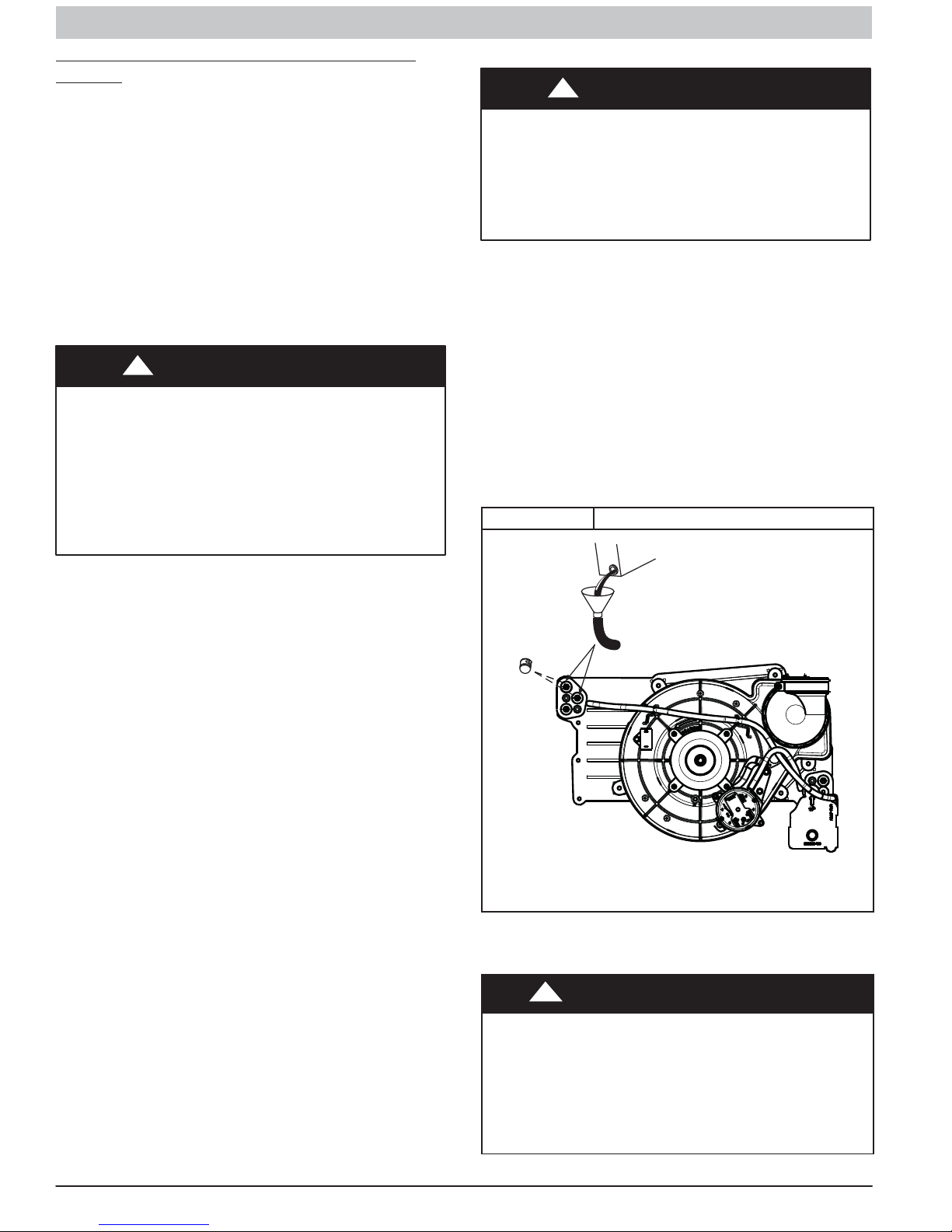
Prime Condensate Trap with Water
!
CAUTION
UNIT OPERATION HAZARD
Failure to follow this caution may result in intermittent unit
operation or performance satisfaction.
Condensate trap must be PRIMED or proper draining may
not occur. The condensate trap has two internal chambers
which can ONLY be primed by pouring water into the
inducer drain side of condensate trap.
1. Remove upper and middle collector box drain plugs
opposite of the condensate trap. (See Figure 1)
2. Connect field-supplied 1/2-in. (13 mm) OD tube to upper
collector box drain connection.
3. Insert field-supplied funnel into tube.
4. Pour one quart of water into funnel/tube. Water should
run through collector box, overfill condensate trap, and
flow into open field drain.
5. Remove funnel; replace collector box drain plug.
6. Connect field-supplied 1/2-in. (13 mm) OD tube to middle
collector box drain port.
7. Pour one quart of water into funnel/tube. Water should
run through collector box, overfill condensate trap, and
flow into open field drain.
8. Remove funnel and tube from collector box and replace
collector box drain plug.
Figure 1 Priming Condensate Drain
Before operating furnace, check flame rollout manual reset
switch for continuity. If necessary, press button to reset switch.
EAC-1 terminal is energized whenever blower operates. HUM
terminal is only energized when low pressure switch is closed
during a call for heat.
There are two humidifier outputs on the furnace control. The
115 VAC HUM terminal is energized when the Induced Draft
Relay closes. The 24 VAC HUM terminal is energized when
the low pressure closes during a call for heat. Connect an
accessory 115 VAC accessory humidifier to the 115 VAC HUM
terminal and L2 on the furnace control. Connect a 24 VAC
humidifier to the 24 VAC HUM terminal and C screw terminal
strip on the control board thermostat strip.
Thermostat Setup Switch
This furnace can be installed with either a singlestage heating
or a twostage heating thermostat. Setup switch (TT) is used to
configure the furnace for single or two stage thermostat
operation. (See Figure 4)
For singlestage thermostats, connect thermostat W to W/W1
at furnace control terminal block. (See Figure 7) For
singlestage thermostats, the control will operate for 12
minutes on low heat, then switch to high heat if heat call
remains. Setup switch (TT) must be in the factoryshipped OFF
position. See Figure 7 and Figure 15 for setup switch
information.
If a twostage heating thermostat is to be used, move setup
switch (TT) to ON position before starting furnace. This
overrides builtin control process for selecting high and low fire
and allows the twostage thermostat to select gas heating
modes. The W2 from thermostat must be connected to W2 on
control terminal block.
Representative drawing only, some models may vary in appearance.
L11F065
Purge Gas Lines
If not previously done, purge the lines after all connections
have been made and check for leaks.
! WARNING
FIRE OR EXPLOSION HAZARD
Failure to follow this warning could result in personal injury,
death, and/or property damage.
Never purge a gas line into a combustion chamber. Never
test for gas leaks with an open flame. Use a commercially
available soap solution made specifically for the detection of
leaks to check all connections. A fire or explosion may result
causing property damage, personal injury or loss of life.
4 440 04 4321 02
Specifications subject to change without notice.
SERVICE AND TECHNICAL SUPPORT MANUAL Gas Furnace: (F/G)9MXT
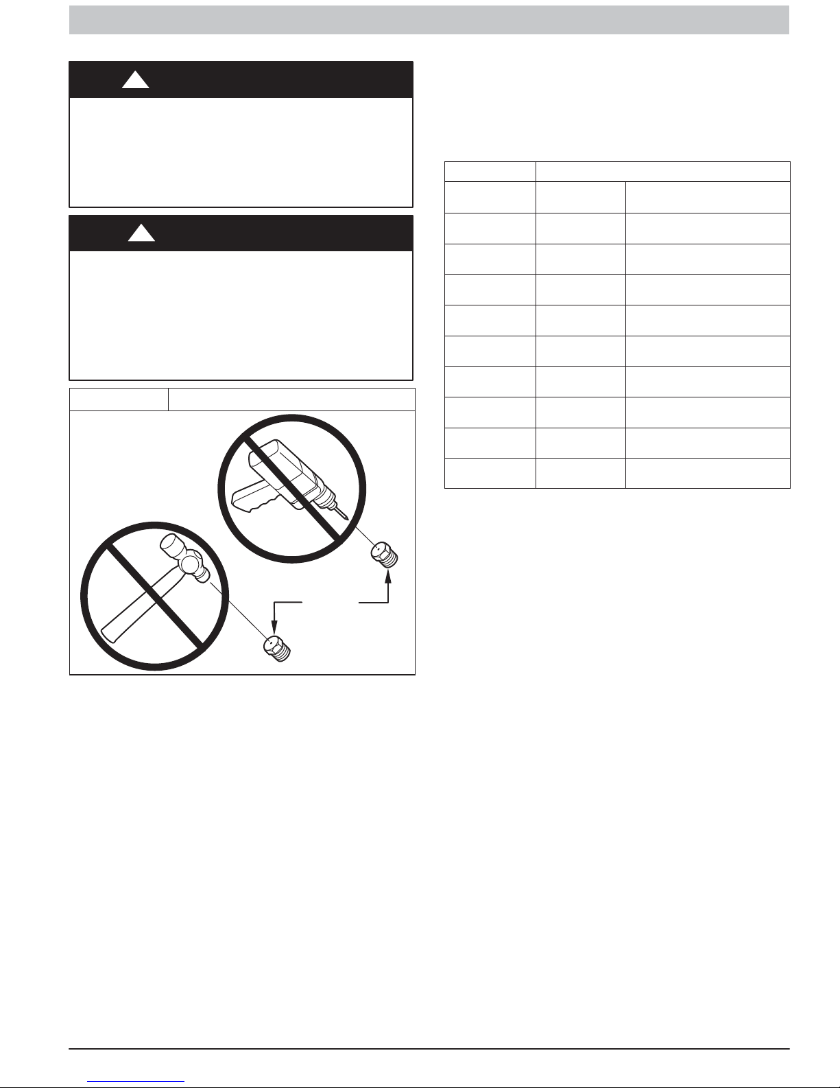
Adjustments
!
FIRE HAZARD
Failure to follow this warning could result in personal
injury, death and/or property damage.
DO NOT bottom out gas valve regulator adjusting screw.
This can result in unregulated manifold pressure and
result in excess overfire and heat exchanger failures.
FURNACE DAMAGE HAZARD
Failure to follow this caution may result in reduced furnace
life.
DO NOT redrill orifices. Improper drilling (burrs,
outofround holes, etc.) can cause excessive burner
noise and misdirection of burner flames. This can result in
flame impingement of heat exchangers, causing failures.
(See Figure 2)
Figure 2 Orifice Hole
For proper operation and long term reliability the furnace input
rate must be within +2 percent of input rate on furnace rating
plate.
The gas input rate on rating plate is for installation at altitudes
up to 2000 ft. (610 M).
In the U.S.A., the input rating for altitudes above 2000 ft. (610
M) must be reduced by 2 percent for each 1000 ft. (305 M)
above sea level refer to Table 1.
In Canada, the input rating must be derated by 5 percent for
altitudes of 2000 ft. (610 M) to 4500 ft. (1372 M) above sea
level.
To adjust manifold pressure to obtain the proper input rate, first,
determine if the furnace has the correct orifice installed. At
higher altitudes or different gas heat contents, it may be
necessary to change the factory orifice to a different orifice.
Tables have been provided in the furnace Service and
Technical Manual to match the required orifice to the manifold
pressure to the heat content and specific gravity of the gas. to
do this:
a. Obtain average yearly gas heat value (at installed
altitude) from local gas supplier.
b. Obtain average yearly gas specific gravity from local
gas supplier.
c. Find installation altitude in Table 2.
WARNING
!
CAUTION
BURNER
ORIFICE
A93059
d. Find closest natural gas heat value and specific
gravity in Table 2.
e. Follow heat value and specific gravity lines to point of
intersection to find orifice size and lowand highheat
manifold pressure settings for proper operation.
f. Check and verify burner orifice size in furnace.
NEVER ASSUME ORIFICE SIZE. ALWAYS CHECK
AND VERIFY.
Table 1 Altitude Derate Multiplier for U.S.A.
ALTITUDE
FT. (M)
0–2000
(0610)
2001–3000
(610914)
3001–4000
(9141219)
4001–5000
(12191524)
5001–6000
(15241829)
6001–7000
(18292134)
7001–8000
(21342438)
8001–9000
(24382743)
9001–10,000
(27433048)
* Derate multiplier factors are based on midpoint altitude for altitude range.
NOTE: For Canadian altitudes of 2000 to 4500 ft. (610 to
1372 M), use USA altitudes of 2001 to 3000 ft. (610 to 914
M)
NOTE: If orifice hole appears damaged or it is suspected to
have been redrilled, check orifice hole with a numbered drill bit
of correct size. Never redrill an orifice. A burrfree and squarely
aligned orifice hole is essential for proper flame characteristics.
g. Replace orifice with correct size, if required by
Table 2. Use only factorysupplied orifices. See
EXAMPLE.
EXAMPLE: 0 - 2000 ft. (0 - 609.6M) altitude
Heating value = 1050 Btu/cu ft.
Specific gravity = 0.62
Therefore: Orifice No. 44
Manifold pressure: 3.4-in. w.c. for high heat, 1.4-in. w.c. for low
heat
* Furnace is shipped with No. 44 orifices. In this example, all
main burner orifices are the correct size and do not need to be
changed to obtain proper input rate.
1. Adjust manifold pressure to obtain low fire input rate.
(See Figure 3)
a. Turn gas valve ON/OFF switch to OFF.
b. Remove manifold pressure tap plug from gas valve.
c. Connect a water column manometer or similar device
to manifold pressure tap.
d. Turn gas valve ON/OFF switch to ON.
e. Move setup switch (TT) on furnace control to ON
position to lock furnace in lowheat operation. (See
Figure 4 and Figure 15)
f. Manually close blower door switch.
g. Jumper R and W/W1 thermostat connections on
control to start furnace. (See Figure 4)
h. Remove regulator adjustment cap from low heat gas
valve pressure regulator (See Figure 3) and turn
lowheat adjusting screw (3/16 or smaller flattipped
PERCENT
OF DERATE
0 1.00
46 0.95
68 0.93
810 0.91
1012 0.89
1214 0.87
1416 0.85
1618 0.83
1820 0.81
DERATE MULTIPLIER
FACTOR*
440 04 4321 02 5
Specifications subject to change without notice.
SERVICE AND TECHNICAL SUPPORT MANUAL Gas Furnace: (F/G)9MXT
screwdriver) counterclockwise (out) to decrease input
rate or clockwise (in) to increase input rate.
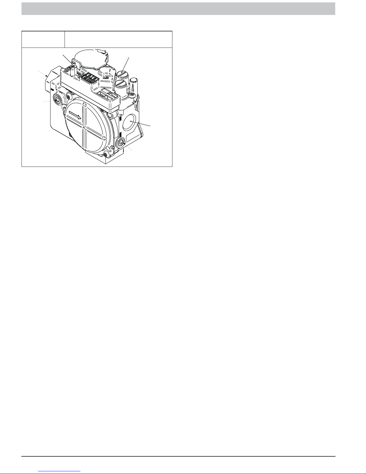
Figure 3
1/2” NPT Inlet
1/8” NPT Inlet
Pressure Tap
Redundant Automatic Gas Control
Valve (2Stage)
ON/OFF Switch
Regulator Seal Cap
Regulator Adjustment
Regulator Seal Cap under Cap
1/8” NPT Manifold
Pressure Tap
1/2” NPT Outlet
A11152
NOTE: DO NOT set lowheat manifold pressure less than
1.3in. w.c. or more than 1.7in. w.c. for natural gas. If manifold
pressure is outside this range, change main burner orifices.
i. Install lowheat regulator adjustment cap.
j. Move setup switch switch (TT) to off position after
completing lowheat adjustment.
k. Leave manometer or similar device connected and
proceed to Step 4.
2. Adjust manifold pressure to obtain high fire input rate.
(See Figure 3)
a. Jumper R to W/W1 and W2 thermostat connections
on furnace control. This keeps furnace locked in
highheat operation.
b. Remove regulator adjustment cap from highheat
gas valve pressure regulator (See Figure 3) and turn
high heat adjusting screw (3/16in. or smaller
flattipped screwdriver) counterclockwise (out) to
decrease input rate or clockwise (in) to increase input
rate.
NOTE: DO NOT set highheat manifold pressure less than
3.2in. w.c. or more than 3.8 in. w.c. for natural gas. If manifold
pressure is outside this range, change main burner orifices to
obtain manifold pressure in this range.
c. When correct input is obtained, replace caps that
conceal gas valve regulator adjustment screws. Main
burner flame should be clear blue, almost
transparent. (See Figure 13)
d. Remove jumpers R to W/W1 and R to W2.
3. Verify natural gas input rate by clocking meter.
a. Turn off all other gas appliances and pilots served by
the meter.
b. Move setup switch switch to ON position. This keeps
furnace locked in lowheat operation.
c. Jumper R to W/W1.
d. Run furnace for 3 minutes in lowheat operation.
e. Measure time (in sec) for gas meter to complete 1
revolution and note reading. The 2 or 5 cubic feet dial
provides a more accurate measurement of gas flow.
f. Refer to Table 5 for cubic ft. of gas per hr.
g. Multiply gas rate cu ft./hr by heating value (Btuh/cu
ft.) to obtain input. If clocked rate does not match
required input from Step 1, increase manifold
pressure to increase input or decrease manifold
pressure to decrease input. Repeat steps b through e
until correct lowheat input is achieved. Reinstall
low heat regulator seal cap on gas valve.
h. Move setup switch switch (TT) to OFF position and
jumper R to W/W1, and W2. This keeps furnace
locked in highheat operation. Repeat items d
through g for highheat operation.
6 440 04 4321 02
Specifications subject to change without notice.
SERVICE AND TECHNICAL SUPPORT MANUAL Gas Furnace: (F/G)9MXT
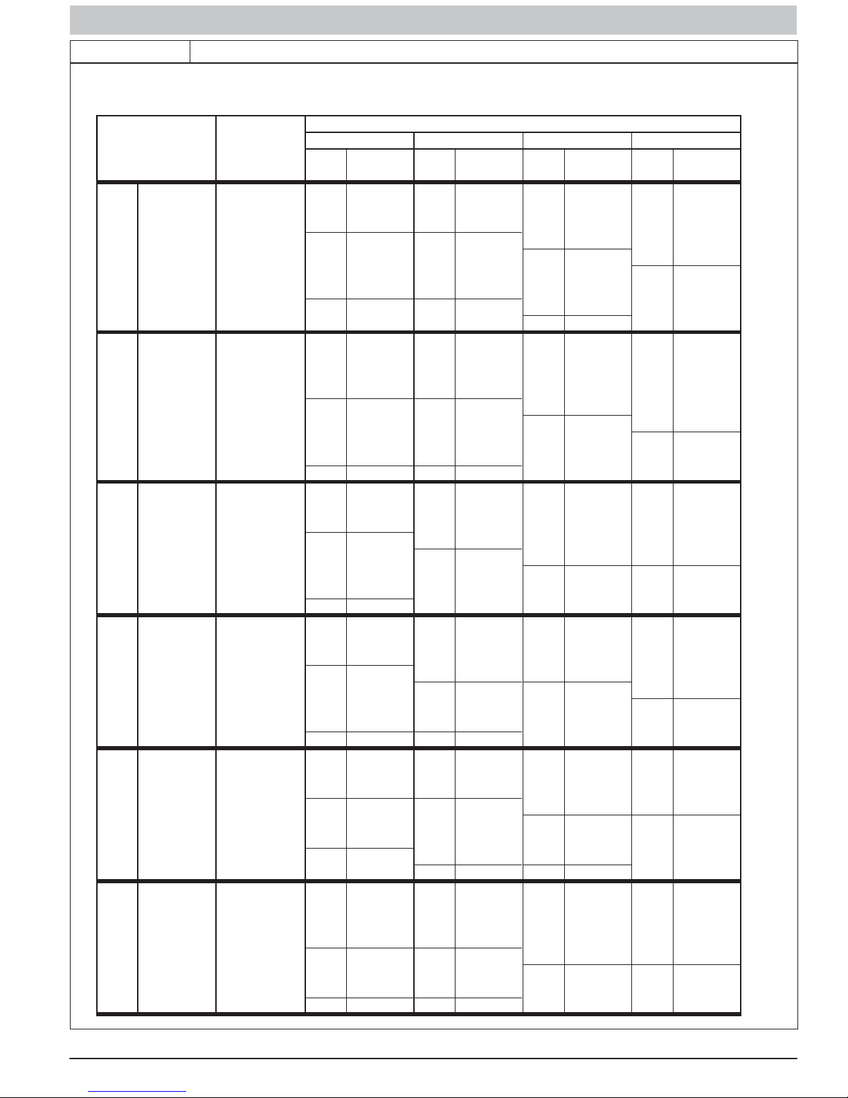
Table 2
Orifice Size and Manifold Pressure (in. w.c.) for Gas Input Rate
TWO-STAGE FURNACE
(TABULATED DATA BASED ON 20,000 BTUH HIGH-HEAT / 13,000 BTUH LOW-HEAT PER BURNER,
DERATED 2%/1000 FT (305M) ABOVE SEA LEVEL)
ALTITUDE
RANGE
ft (m)
092543 3.6 / 1.5 43 3.7 / 1.6 43 3.8 / 1.6 42 3.2 / 1.4
(0) 950 43 3.4 / 1.4 43 3.5 / 1.5 43 3.6 / 1.5 43 3.7 / 1.6
to 1000 44 3.5 / 1.5 44 3.6 / 1.5 44 3.8 / 1.6 43 3.4 / 1.4
U.S.A. and CanadaU.S.A. On
y U.S.A. Only U.S.A. and Canada
l
U.S.A. On
ly
ly
U.S.A. On
2000 1050 44 3.2 / 1.3 44 3.3 / 1.4 44 3.4 / 1.4 44 3.5 / 1.5
(610) 1075 45 3.7 / 1.6 45 3.8 / 1.6 44 3.3 / 1.4 44 3.4 / 1.4
U.S.A. 800 42 3.4 / 1.4 42 3.5 / 1.5 42 3.6 / 1.5 42 3.7 / 1.6
2001 (611) 825 43 3.8 / 1.6 42 3.3 / 1.4 42 3.4 / 1.4 42 3.5 / 1.5
to 850 43 3.6 / 1.5 43 3.7 / 1.6 42 3.2 / 1.3 42 3.3 / 1.4
3000 (914) 875 43 3.4 / 1.4 43 3.5 / 1.5 43 3.7 / 1.5 43 3.8 / 1.6
Canada 925 44 3.5 / 1.5 44 3.6 / 1.5 44 3.8 / 1.6 43 3.4 / 1.4
2001 (611) 950 44 3.3 / 1.4 44 3.4 / 1.5 44 3.6 / 1.5 44 3.7 / 1.6
to 975 44 3.2 / 1.3 44 3.3 / 1.4 44 3.4 / 1.4 44 3.5 / 1.5
4500 (1372) 1000 46 3.8 / 1.6 45 3.8 / 1.6 44 3.2 / 1.4 44 3.3 / 1.4
3001 800 43 3.8 / 1.6 42 3.2 / 1.4 42 3.3 / 1.4 42 3.4 / 1.4
(915) 825 43 3.6 / 1.5 43 3.7 / 1.6 43 3.8 / 1.6 42 3.2 / 1.4
to
4000 900 44 3.4 / 1.4 44 3.5 / 1.5 44 3.7 / 1.5 44 3.8 / 1.6
(1219) 925 44 3.2 / 1.4 44 3.4 / 1.4 44 3.5 / 1.5 44 3.6 / 1.5
4001 775 43 3.7 / 1.6 43 3.8 / 1.6 42 3.3 / 1.4 42 3.4 / 1.4
(1220) 800 43 3.5 / 1.5 43 3.6 / 1.5 43 3.7 / 1.6 43 3.8 / 1.6
to
5000 875 44 3.3 / 1.4 44 3.5 / 1.5 44 3.6 / 1.5 44 3.7 / 1.6
(1524) 900 44 3.2 / 1.3 44 3.3 / 1.4 44 3.4 / 1.4 44 3.5 / 1.5
5001 750 43 3.7 / 1.5 43 3.8 / 1.6 42 3.2 / 1.4 42 3.3 / 1.4
(1525) 775 43 3.4 / 1.4 43 3.5 / 1.5 43 3.7 / 1.5 43 3.8 / 1.6
to
6000 850 44 3.3 / 1.4 44 3.4 / 1.4 44 3.5 / 1.5 44 3.6 / 1.5
(1829) 875 45 3.7 / 1.6 44 3.2 / 1.3 44 3.3 / 1.4 44 3.4 / 1.4
6001 700 42 3.2 / 1.3 42 3.3 / 1.4 42 3.4 / 1.4 42 3.5 / 1.5
(1830) 725 43 3.6 / 1.5 43 3.7 / 1.6 43 3.8 / 1.6 42 3.3 / 1.4
to
7000 800 44 3.4 / 1.4 44 3.5 / 1.5 44 3.6 / 1.5 44 3.7 / 1.6
(2133) 825 44 3.2 / 1.3 44 3.3 / 1.4 44 3.4 / 1.4 44 3.5 / 1.5
HEATVALUE0.580.600.620.64
AT ALTITUDE Orifice Mnfld Press Orifice Mnfld Press Orifice Mnfld Press Orifice Mnfld Press
(Btu/cu ft) No. High/Low No. High/Low No. High/Low No. High/Low
900 43 3.8 / 1.6 42 3.2 / 1.4 42 3.3 / 1.4 42 3.4 / 1.4
975 44 3.7 / 1.6 44 3.8 / 1.6 43 3.4 / 1.5 43 3.6 / 1.5
1025 44 3.3 / 1.4 44 3.5 / 1.5 44 3.6 / 1.5 44 3.7 / 1.6
1100 46 3.7 / 1.6 46 3.8 / 1.6 45 3.8 / 1.6 44 3.2 / 1.4
900 44 3.7 / 1.6 44 3.8 / 1.6 43 3.5 / 1.5 43 3.6 / 1.5
775 42 3.3 / 1.4 42 3.4 / 1.4 42 3.5 / 1.5 42 3.6 / 1.5
850 44 3.8 / 1.6 43 3.5 / 1.5 43 3.6 / 1.5 43 3.7 / 1.6
875 44 3.6 / 1.5 44 3.7 / 1.6 43 3.4 / 1.4 43 3.5 / 1.5
950 45 3.7 / 1.6 44 3.2 / 1.3 44 3.3 / 1.4 44 3.4 / 1.4
750 42 3.3 / 1.4 42 3.4 / 1.4 42 3.5 / 1.5 42 3.6 / 1.5
825 44 3.8 / 1.6 43 3.4 / 1.4 43 3.5 / 1.5 43 3.6 / 1.5
850 44 3.5 / 1.5 44 3.7 / 1.5 44 3.8 / 1.6 43 3.4 / 1.4
925 46 3.8 / 1.6 45 3.7 / 1.6 44 3.2 / 1.4 44 3.3 / 1.4
725 42 3.2 / 1.4 42 3.3 / 1.4 42 3.4 / 1.5 42 3.5 / 1.5
800 44 3.7 / 1.6 44 3.8 / 1.6 43 3.4 / 1.5 43 3.5 / 1.5
825 44 3.5 / 1.5 44 3.6 / 1.5 44 3.7 / 1.6 44 3.8 / 1.6
900 46 3.7 / 1.6 46 3.8 / 1.6 45 3.8 / 1.6 44 3.2 / 1.4
675 42 3.4 / 1.4 42 3.5 / 1.5 42 3.6 / 1.5 42 3.8 / 1.6
750 43 3.4 / 1.4 43 3.5 / 1.5 43 3.6 / 1.5 43 3.7 / 1.6
775 44 3.6 / 1.5 44 3.7 / 1.6 43 3.4 / 1.4 43 3.5 / 1.5
850 46 3.8 / 1.6 45 3.8 / 1.6 44 3.2 / 1.4 44 3.3 / 1.4
SAGLARUTANFOYTIVARGCIFICEPSSAG.GVA
A11252A
440 04 4321 02 7
Specifications subject to change without notice.
SERVICE AND TECHNICAL SUPPORT MANUAL Gas Furnace: (F/G)9MXT
Table 2 (CONT.)
Orifice Size and Manifold Pressure (in. w.c.) for Gas Input Rate
(TABULATED DATA BASED ON 20,000 BTUH HIGH-HEAT / 13,000 BTUH LOW-HEAT PER BURNER,
DERATED 2%/1000 FT (305M) ABOVE SEA LEVEL)
ALTITUDE
RANGE
HEATVALUE0.580.600.620.64
AT ALTITUDE Orifice Mnfld Press Orifice Mnfld Press Orifice Mnfld Press Orifice Mnfld Press
ft (m)
(Btu/cu ft) No. High/Low No. High/Low No. High/Low No. High/Low
650 42 3.4 / 1.4 42 3.5 / 1.5 42 3.6 / 1.5 42 3.7 / 1.6
7001 675 43 3.8 / 1.6 42 3.2 / 1.4 42 3.3 / 1.4 42 3.4 / 1.5
(2134) 700 43 3.5 / 1.5 43 3.7 / 1.5 43 3.8 / 1.6 42 3.2 / 1.4
to
725 44 3.8 / 1.6 43 3.4 / 1.4 43 3.5 / 1.5 43 3.6 / 1.5
750 44 3.5 / 1.5 44 3.7 / 1.5 44 3.8 / 1.6 43 3.4 / 1.4
8000 775 44 3.3 / 1.4 44 3.4 / 1.4 44 3.5 / 1.5 44 3.7 / 1.5
(2438) 800 45 3.8 / 1.6 44 3.2 / 1.4 44 3.3 / 1.4 44 3.4 / 1.4
825 46 3.7 / 1.6 46 3.8 / 1.6 45 3.8 / 1.6 44 3.2 / 1.4
625 42 3.4 / 1.4 42 3.5 / 1.5 42 3.6 / 1.5 42 3.7 / 1.6
8001 650 43 3.8 / 1.6 42 3.2 / 1.4 42 3.3 / 1.4 42 3.4 / 1.4
(2439) 675 43 3.5 / 1.5 43 3.6 / 1.5 43 3.7 / 1.6 42 3.2 / 1.3
to
U.S.A. OnlyU.S.A. Only U.S.A. Only
9000 750 44 3.3 / 1.4 44 3.4 / 1.4 44 3.5 / 1.5 44 3.6 / 1.5
700 44 3.7 / 1.6 43 3.4 / 1.4 43 3.5 / 1.5 43 3.6 / 1.5
725 44 3.5 / 1.5 44 3.6 / 1.5 44 3.7 / 1.6 44 3.8 / 1.6
(2743) 775 45 3.7 / 1.6 44 3.2 / 1.3 44 3.3 / 1.4 44 3.4 / 1.4
9001 600 42 3.3 / 1.4 42 3.4 / 1.5 42 3.6 / 1.5 42 3.7 / 1.6
(2744) 625 43 3.7 / 1.6 42 3.2 / 1.3 42 3.3 / 1.4 42 3.4 / 1.4
to
650 43 3.5 / 1.5 43 3.6 / 1.5 43 3.7 / 1.6 43 3.8 / 1.6
675 44 3.7 / 1.6 44 3.8 / 1.6 43 3.4 / 1.4 43 3.5 / 1.5
10000 700 44 3.4 / 1.4 44 3.5 / 1.5 44 3.7 / 1.5 44 3.8 / 1.6
(3048) 725 44 3.2 / 1.3 44 3.3 / 1.4 44 3.4 / 1.4 44 3.5 / 1.5
* Orifice numbers shown in BOLD are f actory-ins talled.
TWO-STAGE FURNACE
SAGLARUTANFOYTIVARGCIFICEPSSAG.GVA
A11252B
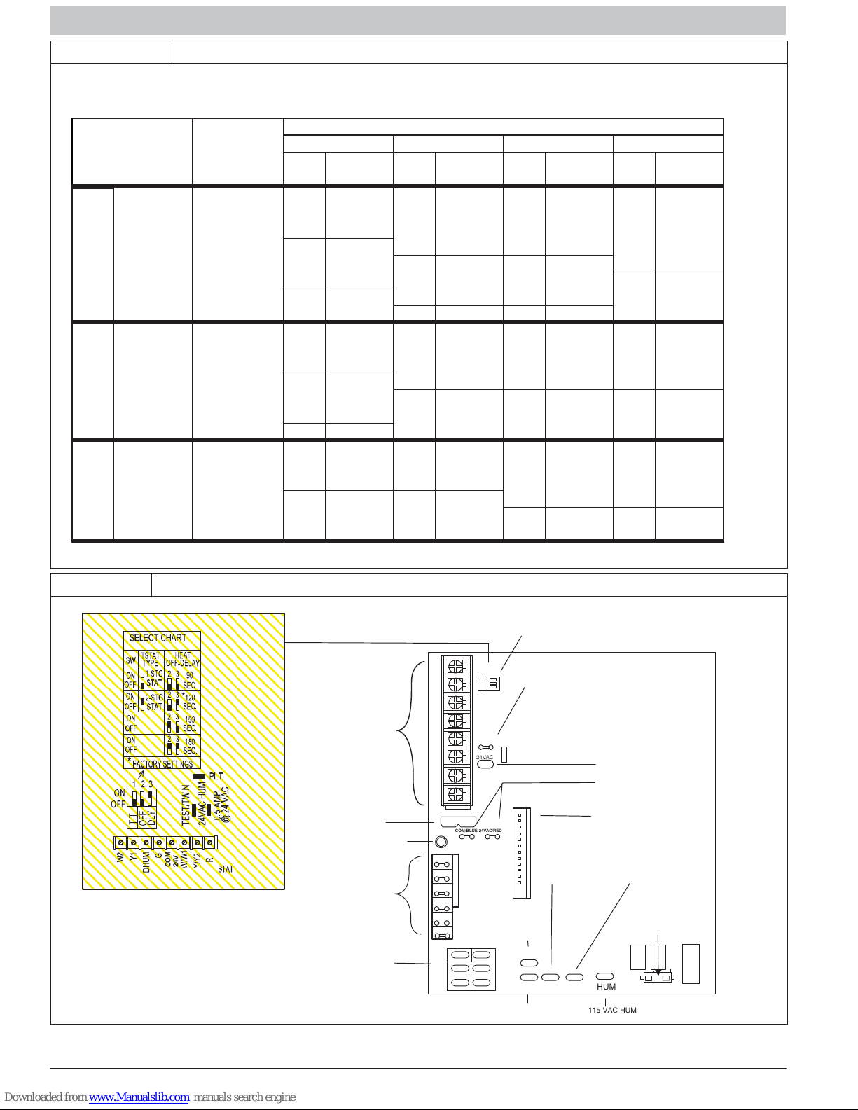
Figure 4 Furnace Control Board
COM
24V
24V THERMOS TAT
TERMINALS
3AMP FUSE
LED OPERATION
& DIAGNOSTIC LIGHT
BLOWER SPEED
TERMINALS
115VAC (L2)
NEUTRAL
CONNECTIONS
SET UP SWITCHES
THERMOSTAT TYPE (TT)
AND HEAT OFFDELAY
W2 Y1 DHUM G COM W/W1 Y/Y2 R
24V
FUSE 3AMP
COM
HI HT
COOL
LO H T
SPARE 2
SPARE 1
L2
TEST / TWIN
24VAC
COM/BLUE 24VAC/RED
24V MTR TAPS
EAC2
TWINNING AND/OR
ON
OFF
COMPONENT TEST
1 2 3
TT
TERMINAL
OFF
DLY
PLT
HUM
PL1
1
EAC TERMINAL
115 VAC 1.0 AMP
MAX
EAC1
11 5 VAC
BLOWER POWER (BL1)
CONNECTION
L1 BL1 XFMR
115 VAC LINE (L1)
INPUT
HUMIDIFIER TERMINAL
(24 VAC 0.5 AMPS MAX)
TRANSFORMER
24 VAC CONNECTIONS
P1 LOW VOLTAGE
11 5 VAC
TRANSFORMER
PRIMARY
P2 HOT SURFACE
IGNITER/INDUCE R
MOTOR CONNECTION
IDR
HSIR
1
PL2
HUM
115 VAC HUM
HSI HI LO
IHI/LOR
IDM
8 440 04 4321 02
Specifications subject to change without notice.
SERVICE AND TECHNICAL SUPPORT MANUAL Gas Furnace: (F/G)9MXT
Adjust Temperature Rise
NOTE: Blower door must be installed when taking temperature
rise reading. Leaving blower door off will result in incorrect
temperature measurements.
!
CAUTION
FURNACE OVERHEATING HAZARD
Failure to follow this caution may result in shortened furnace
life.
Set air temperature rise within limits specified on the rating
plate to prevent reduced life of furnace components.
!
CAUTION
FURNACE DAMAGE HAZARD
Failure to follow this caution may result in overheating the
heat exchangers or condensing flue gases in heat
exchanger areas not designed for condensate.
Temperature rise must be within limits specified on unit
rating plate.
!
CAUTION
UNIT DAMAGE HAZARD
Failure to follow this caution may result in component
damage.
Temperature rise must be within limits specified on furnace
rating plate. Recommended operation is at midpoint of rise
range or slightly above.
Place setup switch (TT) in ON position. Jumper R to W/W1 and
W2 to check highgasheat temperature rise. To check
lowgasheat temperature rise, remove jumper to W2.
Determine air temperature rise for both high and low gas heat.
Do not exceed temperature rise ranges specified on unit rating
plate for high and low gas heat.
This furnace must operate within the temperature rise ranges
specified on the furnace rating plate. Determine the air
temperature as follows:
a. Place duct thermometers in return and supply ducts
as close to furnace as possible. Be sure
thermometers do not “see” heat exchangers so that
radiant heat does not affect thermometer readings.
This is particularly important with straight run ducts.
b. When thermometer readings stabilize, subtract
returnair temperature from supplyair temperature to
determine temperature rise.
If the temperature rise is outside this range, check the
following:
a. Gas input for lowand high gas heat operation.
b. Derate for altitude if applicable.
c. Return and supply ducts for excessive restrictions
causing static pressures greater than 0.50in. w.c.
d. Adjust temperature rise by adjusting blower speed.
e. Increase blower speed to reduce temperature rise.
f. Decrease blower speed to increase temperature rise.
!
ELECTRICAL OPERATION HAZARD
Failure to follow this warning could result in personal injury
or death.
Disconnect 115V electrical power before changing speed
tap.
WARNING
Table 3 Blower Speed Taps
COLOR SPEED FACTORY ATTACHED TO:
Gray 5 Cool
Yellow 4 Spare
Blue 3 HI HT
Orange 2 Spare
Red 1 LO HT/Cont. Fan
For lowheat, the following connections can be made at
LOHT on control:
a. Speed 2 (Orange)
b. Speed 1 (Red) Factory Setting
(Read following caution before changing taps).
!
CAUTION
UNIT DAMAGE HAZARD
To avoid operating outside the rise range and avoid
component damage:
1. NEVER connect Speed Tap 1 (Red) wire to “HI HT.”
2. NEVER connect Speed Tap 2 (Orange) wire to “HI
HT” on all models.
To change blower motor speed selections for heating mode,
remove blower motor lead from control HIHT terminal. (See
Figure 4) Select desired blower motor speed lead from one of
the other motor leads and relocate it to HIHT terminal. (See
Table 3 for lead color identification.) Reconnect original lead on
SPARE terminal. Follow this same procedure for proper
selection of LOHT and COOL speed selection.
Adjust Blower Off Delay (Heat Mode)
If desired, the main blower off time delay period may be
lengthened or shortened when operating in the heating mode
to provide greater comfort. For position of switches see
Figure 4 and Figure 15 for location of switches on control
center.
a. Remove blower door if installed.
b. Turn setup switches ON or OFF for desired blower off
delay. See Table 4, Figure 4 and Figure 15.
c. Proceed to “Set Blower Off Delay” before installing
blower door.
Table 4 Blower Speed Taps
DESIRED HEATING MODE
BLOWER OFF DELAY
(SEC.)
90 OFF OFF
120 OFF ON
150 ON OFF
180 ON ON
SETUP SWITCH
(SW-2 & SW-3)
POSITION
SW-2 SW-3
Adjust Cooling Airflow
The cooling airflow can be set from the remaining blower speed
taps. Refer to the Air Delivery Tables in these instructions.
If a two stage air conditioning or heat pump is installed, the Low
Cooling Speed is the same speed tap as the Lo Heat speed.
440 04 4321 02 9
Specifications subject to change without notice.
 Loading...