

International comfort products G9MXE0401410A, F9MXE0401714A, F9MXE0601714A, G9MXE0601714A, G9MXE0401714A Service And Technical Support Manual
...
SERVICE AND TECHNICAL
SUPPORT MANUAL
Single Stage, ECM Blower Motor
35” Tall, High Efficiency Condensing Gas Furnace
(F/G)9MXE
Save this manual for future reference.
Safety Labeling and Signal Words
DANGER, WARNING, CAUTION, and NOTE
The signal words DANGER, WARNING,
CAUTION, and NOTE are used to identify levels of
hazard seriousness. The signal word DANGER is
only used on product labels to signify an immediate
hazard. The signal words WARNING, CAUTION,
and NOTE will be used on product labels and
throughout this manual and other manual that may
apply to the product.
DANGER − Immediate hazards which will result in
severe personal injury or death.
WARNING − Hazards or unsafe practices which
could result in severe personal injury or death.
CAUTION − Hazards or unsafe practices which
may result in minor personal injury or product or
property damage.
NOTE − Used to highlight suggestions which will
result in enhanced installation, reliability, or
operation.
Signal Words in Manuals
The signal word WARNING is used throughout
this manual in the following manner:
!
WARNING
The signal word CAUTION is used throughout
this manual in the following manner:
!
CAUTION
Signal Words on Product Labeling
Signal words are used in combination with
colors and/or pictures or product labels.
Safety−alert symbol
When you see this symbol on the unit and in
instructions or manuals, be alert to the
potential for personal injury.
TABLE OF CONTENTS
START−UP, ADJUSTMENT, AND SAFETY CHECK 4...........
PRIME CONDENSATE TRAP WITH WATER 4.................
PURGE GAS LINES 4......................................
ADJUST TEMPERATURE RISE 10............................
ADJUST BLOWER OFF DELAY (HEAT MODE) 11..............
ADJUST COOLING AIRFLOW 11.............................
ADJUST CONTINUOUS FAN AIRFLOW 11....................
ADJUST THERMOSTAT HEAT ANTICIPATOR 11...............
CHECK SAFETY CONTROLS 11.............................
CHECKLIST 12.............................................
SERVICE AND MAINTENANCEPROCEDURES 13..............
RETRIEVING STORED FAULT CODES 14.....................
COMPONENT SELF−TEST 14...............................
CARE AND MAINTENANCE 15...............................
CLEANING AND/OR REPLACING AIR FILTER 15..............
BLOWER MOTOR AND WHEEL MAINTENANCE 15............
CLEANING BURNERS AND FLAME SENSOR 17...............
SERVICING HOT SURFACE IGNITER 18......................
FLUSHING COLLECTOR BOX AND DRAINAGE SYSTEM 18....
CLEANING CONDENSATE DRAIN AND TRAP 19..............
CLEANING HEAT EXCHANGERS 19..........................
WINTERIZATION 20........................................
SERVICE LABEL 21.........................................
WIRING DIAGRAM 22.......................................
TROUBLESHOOTING GUIDE − FLOW CHART 23.............
SEQUENCE OF OPERATION 25.............................
PARTS REPLACEMENT INFORMATION GUIDE 29.............
PRODUCT NOMENCLATURE 30.............................
MODELS
(F/G)9MXE0401410A
(F/G)9MXE0401714A
(F/G)9MXE0601412A
(F/G)9MXE0601714A
(F/G)9MXE0801716A
(F/G)9MXE0802120A
(F/G)9MXE1002120A
(F/G)9MXE1202422A
Use of the AHRI Certified TM Mark indicates a
manufacturer’s participation in the program.
For verification of certification for individual
products, go to www.ahridirectory.org .
Printed in U.S.A. 440 04 4311 05 12/5/2013
SAFETY CONSIDERATIONS
Improper installation, adjustment, alteration, service,
maintenance, or use can cause explosion, fire, electrical shock,
or other conditions which may cause death, personal injury, or
property damage. Consult a qualified installer, service agency,
or your distributor or branch for information or assistance. The
qualified installer or agency must use factory−authorized kits or
accessories when modifying this product. Refer to the individual
instructions packaged with the kits or accessories when
installing.
Follow all safety codes. Wear safety glasses, protective clothing,
and work gloves. Use quenching cloth for brazing operations.
Have fire extinguisher available. Read these instructions
thoroughly and follow all warnings or cautions included in
literature and attached to the unit. Consult local building codes,
the current editions of the National Fuel Gas Code (NFCG)
NFPA 54/ANSI Z223.1, and the National Electrical Code (NEC)
NFPA 70.
In Canada refer to the current editions of the National standards
of Canada CAN/CSA−B149.1 and .2 Natural Gas and Propane
Installation Codes, and Canadian Electrical Code CSA C22.1.
Recognize safety information. This is the safety−alert symbol
. When you see this symbol on the unit and in instructions or
manuals, be alert to the potential for personal injury.
Understand these signal words; DANGER, WARNING, and
CAUTION. These words are used with the safety−alert symbol.
DANGER identifies the most serious hazards which will result in
severe personal injury or death. WARNING signifies hazards
which could result in personal injury or death. CAUTION is used
to identify unsafe practices which may result in minor personal
injury or product and property damage. NOTE is used to
highlight suggestions which will result in enhanced installation,
reliability, or operation.
!
WARNING
PERSONAL INJURY, AND/OR PROPERTY
DAMAGE HAZARD
Failure to carefully read and follow this warning could
result in equipment malfunction, property damage,
personal injury and/or death.
Installation or repairs made by unqualified persons could
result in equipment malfunction, property damage,
personal injury and/or death.
The information contained in this manual is intended for
use by a qualified service technician familiar with safety
procedures and equipped with proper tools and test
instruments.
Installation must conform with local building codes and
with the Natural Fuel Gas Code (NFCG) NFPA 54/ANSI
Z223.1, and National standards of Canada
CAN/CSA−B149.1 and .2 Natural Gas and Propane
Installation Codes.
!
ELECTRICAL SHOCK HAZARD
Failure to follow this warning could cause personal
injury or death.
Before performing service or maintenance operations
on unit, always turn off main power switch to unit and
install lockout tag. Unit may have more than one power
switch.
!
WARNING
WARNING
CARBON MONOXIDE POISONING AND FIRE
HAZARD
Failure to follow safety warnings could result in personal
injury, death, and/or property damage.
This furnace is not designed for use in mobile homes,
trailers or recreational vehicles.
!
CAUTION
CUT HAZARD
Failure to follow this caution may result in damage
personal injury.
Sheet metal parts may have sharp edges or burrs. Use
care and wear appropriate protective clothing, safety
glasses and gloves when handling parts and servicing
furnaces.
2
Specifications are subject to change without notice.
440 04 4311 08
SERVICE AND TECHNICAL MANUAL Gas Furnace: (F/G)9MXE
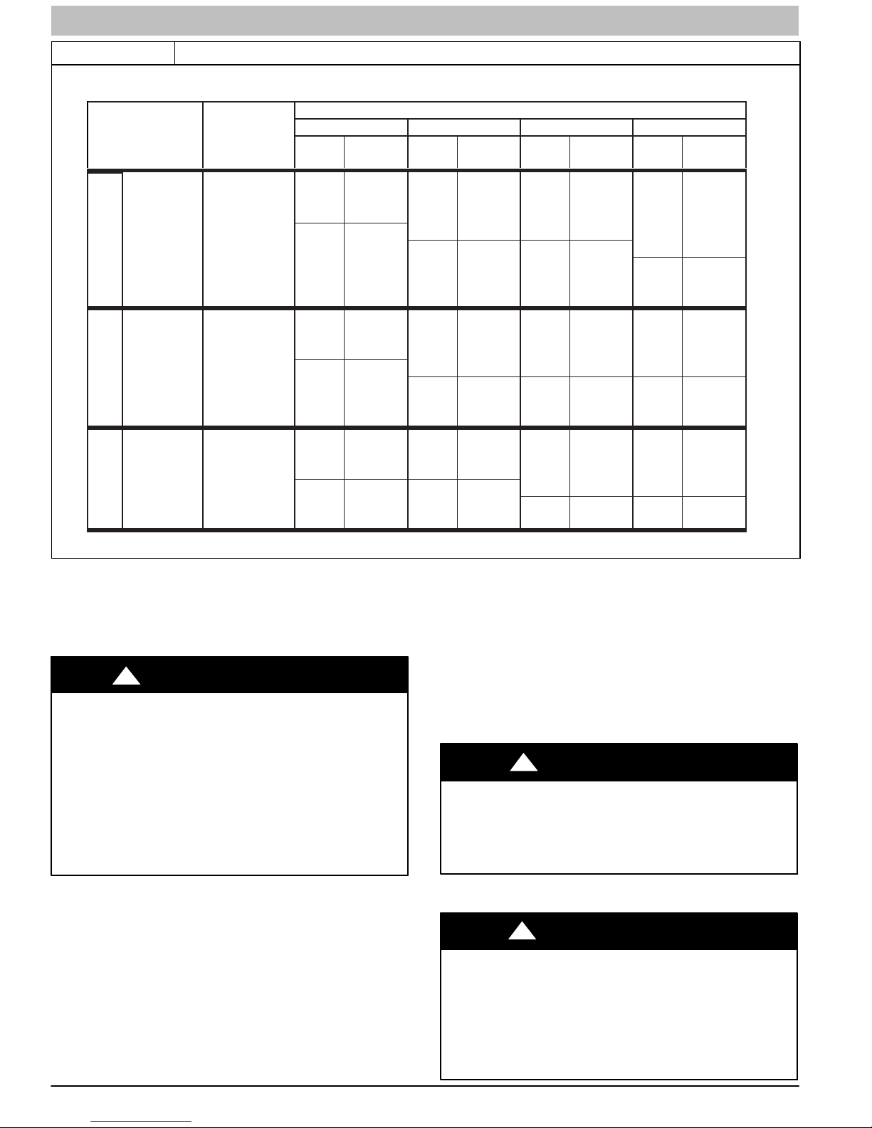
START−UP CHECK SHEET
For ECM Models (F/G)9MXE
(This sheet is optional. Keep for future reference.)
Date of Start−Up:
Dealer Name:
Address:
City, State(Province), Zip or Postal Code:
Phone:
Owner Name:
Address:
City, State(Province), Zip or Postal Code:
Model Number:
Serial Number:
Setup Checks
Check the box when task is complete.
Calculated Input (BTU) Rate: (See Checks and Adjustments
Section).
Heating Check
Measured Line Pressure During Heat:
Measured Manifold Pressure: Heat
Temperature of Supply Air: Heat
Temperature of Return Air:
Temperature Rise (Supply − Return): Heat
In Rise Range (see furnace rating plate)?
Static Pressure (Ducts) High Heat: Supply
Return
The Blower Speed Tap used for: Heat
Optional Check: CO?
CO2?
Cooling Check
All Electrical Connections Tight?
Have hoses been relocated for furnace U/D/H application?
Condensate Drain Connected?
Condensate Drain Trapped?
Manual Gas Shut−off Upstream of Furnace/Drip Leg
Gas Valve turned ON?
Type of Gas: Natural: Propane:
Filter Type and Size:
Check in box the Blower OFF Delay Jumper Heating Position
for Fan “Time OFF” Setting:
1 and 2
90 120 150 180
2 and 3 3 and 4 5 and 6
Temperature of Supply Air:
Temperature of Return Air:
Temperature Difference:
Static Pressure (Ducts) Cooling: Supply
Return
The Blower Speed Tap used for: Cooling
Dealer Comments:
440 04 4311 08 3
Specifications subject to change without notice.
SERVICE AND TECHNICAL SUPPORT MANUAL Gas Furnace: (F/G)9MXE
START−UP, ADJUSTMENT, AND SAFETY
CHECK
NOTICE
IMPORTANT INSTALLATION AND START−UP
PROCEDURES
Failure to follow this procedure may result in a nuisance smoke
or odor complaint.
The manifold pressure, gas rate by meter clocking, temperature
rise and operation must be checked after installation. Minor
smoke and odor may be present temporarily after start−up from
the manufacturing process. Some occupants are more
sensitive to this minor smoke and odor. It is recommended that
doors and windows be open during the first heat cycle.
General
1. Furnace must have a 115-v power supply properly
connected and grounded.
NOTE: Proper polarity must be maintained for 115-v wiring.
Control status indicator light flashes rapidly (Status Code 10)
and furnace does not operate if polarity is incorrect or if the
furnace is not grounded.
2. Thermostat wire connections at terminals R, W, G, and
Y1 and Y/Y2 must be made at 24-v terminal block on
furnace control.
3. Natural gas service pressure must not exceed 0.5 psig
(14- in. w.c., 1125 Pa), but must be no less than 0.16
psig (4.5-in. w.c., 350 Pa).
4. Blower door must be in place to complete 115-v electrical
circuit and supply power to the furnace components.
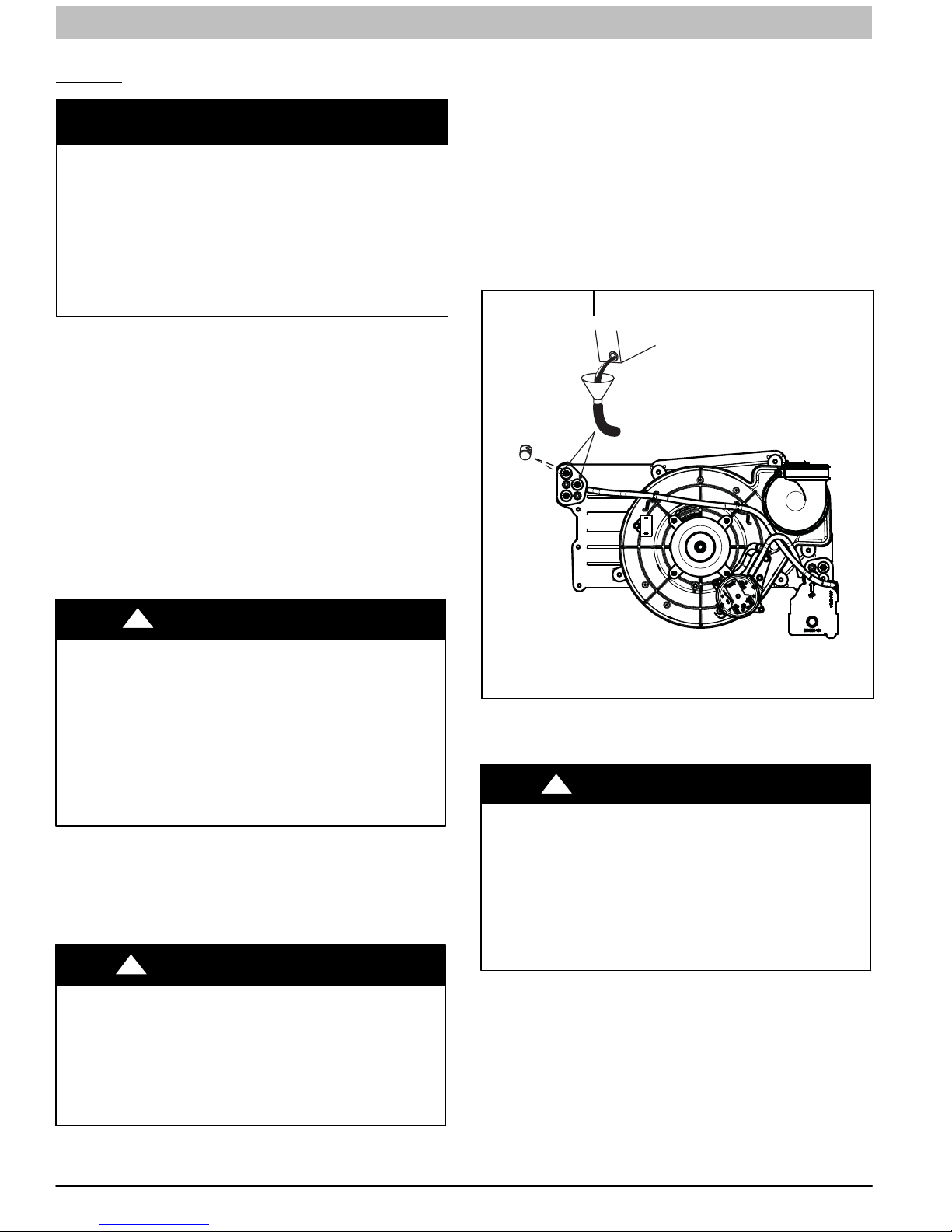
2. Connect field-supplied 5/8-in. (16 mm) ID tube with
attached funnel (see Figure 1) to upper collector box
drain connection.
3. Pour one quart (liter) of water into funnel/tube. Water
should run through collector box, overfill condensate
trap, and flow into open field drain.
4. Remove funnel; replace collector box drain plug.
5. Connect field-supplied 5/8-in. (16 mm) ID tube to middle
collector box drain port.
6. Pour one quart (liter) of water into funnel/tube. Water
should run through collector box, overfill condensate
trap, and flow into open field drain.
7. Remove funnel and tube from collector box and replace
collector box drain plug.
Figure 1 Priming Condensate Drain
!
CAUTION
UNIT OPERATION HAZARD
Failure to follow this caution may result in intermittent unit
operation or performance satisfaction.
These furnaces are equipped with a manual reset limit
switch in burner assembly. This switch opens and shuts off
power to the gas valve if an overheat condition (flame
rollout) occurs in the burner assembly/enclosure. Correct
inadequate combustion−air supply, improper gas pressure
setting, improper burner or gas orifice positioning, or
improper venting condition before resetting switch. DO
NOT jumper this switch.
Before operating furnace, check flame rollout manual reset
switch for continuity. If necessary, press button to reset switch.
EAC−1 (115vac) terminal is energized whenever blower
operates. HUM (24vac) terminal is only energized the draft
inducer is energized in heating.
Prime Condensate Trap with Water
!
CARBON MONOXIDE POISONING HAZARD
Failure to follow these warnings could result in personal
injury or death.
Failure to use a properly configured trap or NOT
water-priming trap before operating furnace may allow
positive pressure vent gases to enter the structure through
drain tube. Vent gases contain carbon monoxide which is
tasteless and odorless.
1. Remove upper and middle collector box drain plugs
opposite of the condensate trap. (See Figure 1)
WARNING
Representative drawing only, some models may vary in appearance.
L11F065
Purge Gas Lines
If not previously done, purge the lines after all connections
have been made and check for leaks.
!
FIRE OR EXPLOSION HAZARD
Failure to follow this warning could result in personal injury,
death, and/or property damage.
Never purge a gas line into a combustion chamber. Never
test for gas leaks with an open flame. Use a commercially
available soap solution made specifically for the detection
of leaks to check all connections. A fire or explosion may
result causing property damage, personal injury or loss of
life.
WARNING
4 440 04 4311 08
Specifications subject to change without notice.
SERVICE AND TECHNICAL SUPPORT MANUAL Gas Furnace: (F/G)9MXE
Adjustments
!
FIRE HAZARD
Failure to follow this warning could result in personal injury,
death and/or property damage.
DO NOT bottom out gas valve regulator adjusting screw.
This can result in unregulated manifold pressure and result
in excess overfire and heat exchanger failures.
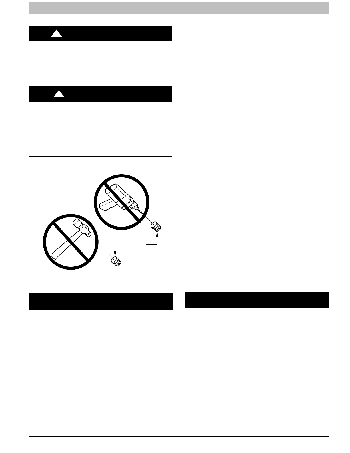
FURNACE DAMAGE HAZARD
Failure to follow this caution may result in reduced furnace
life.
DO NOT redrill orifices. Improper drilling (burrs,
out−of−round holes, etc.) can cause excessive burner
noise and misdirection of burner flames. This can result in
flame impingement of heat exchangers, causing failures.
(See Figure 2)
Figure 2 Orifice Hole
For proper operation and long term reliability the furnace input
rate must be within +/−2 percent of input rate on furnace rating
plate, or as adjusted for altitude.
WARNING
!
CAUTION
BURNER
ORIFICE
A93059
Table 1 Altitude Derate Multiplier for U.S.A.
ALTITUDE
FT. (M)
0–2000
(0−610)
2001–3000
(610−914)
3001–4000
(914−1219)
4001–5000
(1219−1524)
5001–6000
(1524−1829)
6001–7000
(1829−2134)
7001–8000
(2134−2438)
8001–9000
(2438−2743)
9001–10,000
(2743−3048)
* Derate multiplier factors are based on midpoint altitude for altitude range.
NOTE: For Canadian altitudes of 2000 to 4500 ft. (610 to
1372 M), use USA altitudes of 2001 to 3000 ft. (610 to 914
M) in Table 3.
To adjust manifold pressure to obtain the proper input rate, first,
determine if the furnace has the correct orifice installed. At
higher altitudes or different gas heat contents, it may be
necessary to change the factory orifice to a different orifice.
Tables have been provided in the furnace Service and
Technical Manual to match the required orifice to the manifold
pressure to the heat content and specific gravity of the gas. To
do this:
1. Obtain average yearly gas heat value (at installed
altitude) from local gas supplier.
2. Obtain average yearly gas specific gravity from local gas
supplier.
3. Find installation altitude range for your installation in the
manifold pressure tables in Table 3.
4. Find closest natural gas heat value and specific gravity in
Table 3. Follow heat value and specific gravity lines to
point of intersection to find orifice size and low-and
high-heat manifold pressure settings for proper
operation.
5. Check and verify burner orifice size in furnace. NEVER
ASSUME ORIFICE SIZE. ALWAYS CHECK AND
VERIFY.
PERCENT
OF DERATE
0 1.00
4−6 0.95
6−8 0.93
8−10 0.91
10−12 0.89
12−14 0.87
14−16 0.85
16−18 0.83
18−20 0.81
DERATE MULTIPLIER
FACTOR*
NOTICE
The NATURAL GAS manifold pressure adjustments in Table 3
compensate for BOTH altitude AND gas heating value. DO
NOT apply an additional de−rate factor to the pressures shown
in Table 3. The values in this Table and NOT referenced to sea
level; they are AS−MEASURED AT ALTITUDE.
The heating content of natural gas at altitude may already
provide for a reduction in capacity or altitude. Refer to Table 3.
No adjustments to the furnace may be necessary at altitude for
certain gas heating values.
Refer to the instructions provided in the factory-specified
LP/Propane conversion kit for instructions for setting gas
manifold pressures for LP/Propane applications.
In the USA, the input rating for altitudes above 2000 ft. (610 M)
must be reduced by 2 percent for each 1000 ft. (305 M) above
sea level refer to Table 1. The natural gas manifold pressures
in Table 3 adjust for BOTH altitude and natural gas heating
value.
In Canada, the input rating must be reduced by 5 percent for
altitudes of 2000 ft. to 4500 ft. (610 to 1372 M) above sea level.
The natural gas manifold pressures in Table 3 adjust for BOTH
altitude and natural gas heating value.
440 04 4311 08 5
NOTICE
If orifice hole appears damaged or it is suspected to have been
redrilled, check orifice hole with a numbered drill bit of correct
size. Never redrill an orifice. A burr−free and squarely aligned
orifice hole is essential for proper flame characteristics.
6. Replace orifice with correct size, if required by Table 3.
Use only factory−supplied orifices. See EXAMPLE 1.
EXAMPLE 1:
0 - 2000 ft. (0 - 609.6M) altitude
Heating value = 1050 Btu/cu ft.
Specific gravity = 0.62
Therefore: Orifice No. 44
(Furnace is shipped with No. 44 orifices. In this example, all
main burner orifices are the correct size and do not need to be
changed to obtain proper input rate.)
Manifold pressure: 3.4-in. w.c. (847 Pa).
NOTE: To convert gas manifold Table pressures to Pascals,
multiply the in.w.c. value by 249.1 Pa/in. w.c. (1 in. wc. = 249.1
Pa).
Specifications subject to change without notice.
SERVICE AND TECHNICAL SUPPORT MANUAL Gas Furnace: (F/G)9MXE
Check Inlet Gas Pressure
The inlet gas pressure must be checked with the furnace
operating in maximum heat. This is necessary to make sure the
inlet gas pressure does not fall below the minimum pressure of
4.5 in. w.c.
1. Make sure the gas supply is turned off to the furnace and
at the electric switch on the gas valve.
2. Remove the 1/8 in. NPT plug from the inlet pressure tap
on the gas valve.
3. Connect a manometer to the inlet pressure tap on gas
valve.
4. Turn on furnace power supply.
5. Turn gas supply manual shutoff valve to ON position.
6. Turn furnace gas valve switch to ON position.
7. Jumper R and W thermostat connections at the furnace
control board.
8. When main burners ignite, confirm inlet gas pressure is
between 4.5 in. w.c. (1125 Pa) and 13.6 in. w.c. (3388
Pa).
9. Remove jumper across thermostat connections to
terminate call for heat. Wait until the blower off delay is
completed.
10. Turn furnace gas valve electric switch to OFF position.
11. Turn gas supply manual shutoff valve to OFF position.
12. Turn off furnace power supply.
13. Remove manometer from the inlet pressure tap of the
gas valve.
!
WARNING
FIRE HAZARD
Failure to follow this warning could result in personal injury,
death, and/or property damage.
Re−install manifold pressure tap plug in gas valve to
prevent gas leak.
14. Apply pipe dope sparingly to end of inlet gas pipe plug
and re−install in the gas valve.
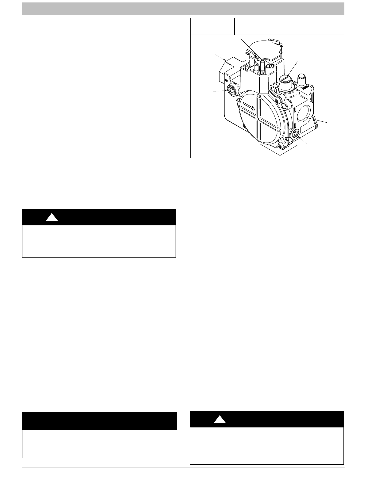
Adjust Manifold Pressure
1. Adjust manifold pressure to obtain proper gas input rate.
(See Figure 3)
a. Turn gas valve ON/OFF switch to OFF.
b. Remove manifold pressure tap plug from gas valve.
c. Connect a water column manometer or similar device
to manifold pressure tap.
d. Turn gas valve ON/OFF switch to ON.
e. Manually close blower door switch.
f. Jumper R and W thermostat connections on control
to start furnace. (See Figure 4)
NOTE: If orifice hole appears damaged or it is suspected to
have been redrilled, check orifice hole with a numbered drill bit
of correct size. Never redrill an orifice. A burr−free and squarely
aligned orifice hole is essential for proper flame characteristics.
g. Remove regulator adjustment cap from gas valve
pressure regulator (See Figure 3) and turn adjusting
screw (3/16 or smaller flat−tipped screwdriver)
counterclockwise (out) to decrease input rate or
clockwise (in) to increase input rate.
Figure 3
1/2” NPT Inlet
1/8” NPT Inlet
Pressure Tap
Redundant Automatic Gas Valve
(Single Stage)
ON/OFF Switch
Regulator Seal Cap
Regulator Adjustment
Regulator Seal Cap under Cap
1/8” NPT Manifold
Pressure Tap
1/2” NPT Outlet
A11153
h. When correct input is obtained, replace cap that
conceal gas valve regulator adjustment screw. Main
burner flame should be clear blue, almost transparent
(See Figure 13)
i. Remove jumper R to W.
2. Verify natural gas input rate by clocking meter.
NOTE: Contact your HVAC distributor or gas supplier for metric
gas meter Tables, if required.
a. Turn off all other gas appliances and pilots served by
the meter.
b. Jumper R to W.
c. Run furnace for 3 minutes.
d. Measure time (in sec) for gas meter to complete 1
revolution and note reading. The 2 or 5 cubic feet dial
provides a more accurate measurement of gas flow.
e. Refer to Table 2 for cubic ft. of gas per hr.
f. Multiply gas rate cu ft./hr by heating value (Btuh/cu
ft.) to obtain input. If clocked rate does not match
required input from Step 1, increase manifold
pressure to increase input or decrease manifold
pressure to decrease input. Repeat steps b through e
until correct input is achieved. Re−install regulator
seal cap on gas valve.
g. If clocked rate does not match required input from
Step 1, increase manifold pressure to increase input
or decrease manifold pressure to decrease input.
Repeat steps b through e of Step 1 until correct heat
input is achieved. Re--install regulator seal cap on
gas valve.
Restore furnace to normal operating condition.
3.
a. Turn gas valve ON/OFF switch to OFF.
b. Remove water column manometer or similar device
from manifold pressure tap.
c. Replace manifold pressure tap plug to gas valve.
d. Turn gas valve ON/OFF switch to ON.
e. Check for gas leaks and verify furnace operation
NOTICE
DO NOT set low−heat manifold pressure less than 2.8−in. w.c.
(697 Pa) or more than 3.8−in. w.c. (947 Pa) for natural gas. If
required manifold pressure is outside this range, change main
burner orifices.
6 440 04 4311 08
FIRE HAZARD
Failure to follow this warning could result in personal injury,
death, and/or property damage.
Reinstall manifold pressure tap plug in gas valve to prevent
gas leak.
Specifications subject to change without notice.
!
WARNING
SERVICE AND TECHNICAL SUPPORT MANUAL Gas Furnace: (F/G)9MXE
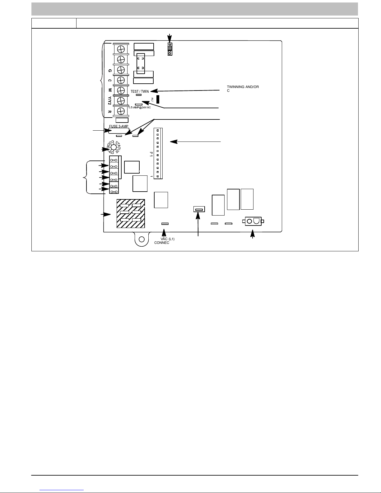
Figure 4 Example of Single Stage Furnace Control for ECM Blower Motor
HEAT OFF−DELAY
120 180
90 150
TWINNING AND/OR
COMPONENT TEST
TERMINAL
HUMIDIFIER TERMINAL
(24−VAC 0.5 AMP MAX)
TRANSFORMER 24VAC
CONNECTIONS
P1 − LOW VOLTAGE MAIN
HARNESS CONNECTOR
24−V THERMOSTAT
3−AMP FUSE
LED OPERATION &
DIAGNOSTIC LIGHT
BLOWER SPEED
SELECTION TERMINALS
TERMINALS
HEAT
COOL
FAN
SPARE2
SPARE1
Y1 DHUM
COM/BLUE
COM
HEAT
COOL
FAN
SPARE 2
SPARE 1
24V MTR TAPS
HUM
24VAC
24VAC/RED
115 −VAC (L2) NEUTRAL
CONNECTIONS
EAC
NEUTRAL − L2
L1
115 VAC (L1)
CONNECTIONS
1 AMP
BL−1
EAC TERMINAL
(115 VAC 1.0 AMP MAX.)
P2
XFMR
IND
HSI
P2−HOT SURFACE IGNITOR (HSI) &
INDUCER MOTOR (IND) CONNECTOR
440 04 4311 08 7
Specifications subject to change without notice.

SERVICE AND TECHNICAL SUPPORT MANUAL Gas Furnace: (F/G)9MXE
Table 2 Gas Rate (CU ft./hr)
SECONDS
FOR 1 REVOLUTION
10 360 720 1800 50 72 144 360
11 327 655 1636 51 71 141 355
12 300 600 1500 52 69 138 346
13 277 555 1385 53 68 136 340
14 257 514 1286 54 67 133 333
15 240 480 1200 55 65 131 327
16 225 450 1125 56 64 129 321
17 212 424 1059 57 63 126 316
18 200 400 1000 58 62 124 310
19 189 379 947 59 61 122 305
20 180 360 900 60 60 120 300
21 171 343 857 62 58 116 290
22 164 327 818 64 56 112 281
23 157 313 783 66 54 109 273
24 150 300 750 68 53 106 265
25 144 288 720 70 51 103 257
26 138 277 692 72 50 100 250
27 133 267 667 74 48 97 243
28 129 257 643 76 47 95 237
29 124 248 621 78 46 92 231
30 120 240 600 80 45 90 225
31 116 232 581 82 44 88 220
32 113 225 563 84 43 86 214
33 109 218 545 86 42 84 209
34 106 212 529 88 41 82 205
35 103 206 514 90 40 80 200
36 100 200 500 92 39 78 196
37 97 195 486 94 38 76 192
38 95 189 474 96 38 75 188
39 92 185 462 98 37 74 184
40 90 180 450 100 36 72 180
41 88 176 439 102 35 71 178
42 86 172 429 104 35 69 173
43 84 167 419 106 34 68 170
44 82 164 409 108 33 67 167
45 80 160 400 11 0 33 65 164
46 78 157 391 11 2 32 64 161
47 76 153 383 11 6 31 62 155
48 75 150 375 120 30 60 150
49 73 147 367
1 Cu Ft. 2 Cu Ft. 5 Cu Ft. 1 Cu Ft. 2 Cu Ft. 5 Cu Ft.
SIZE OF TEST DIAL
SECONDS
FOR 1 REVOLUTION
SIZE OF TEST DIAL
8 440 04 4311 08
Specifications subject to change without notice.
SERVICE AND TECHNICAL SUPPORT MANUAL Gas Furnace: (F/G)9MXE
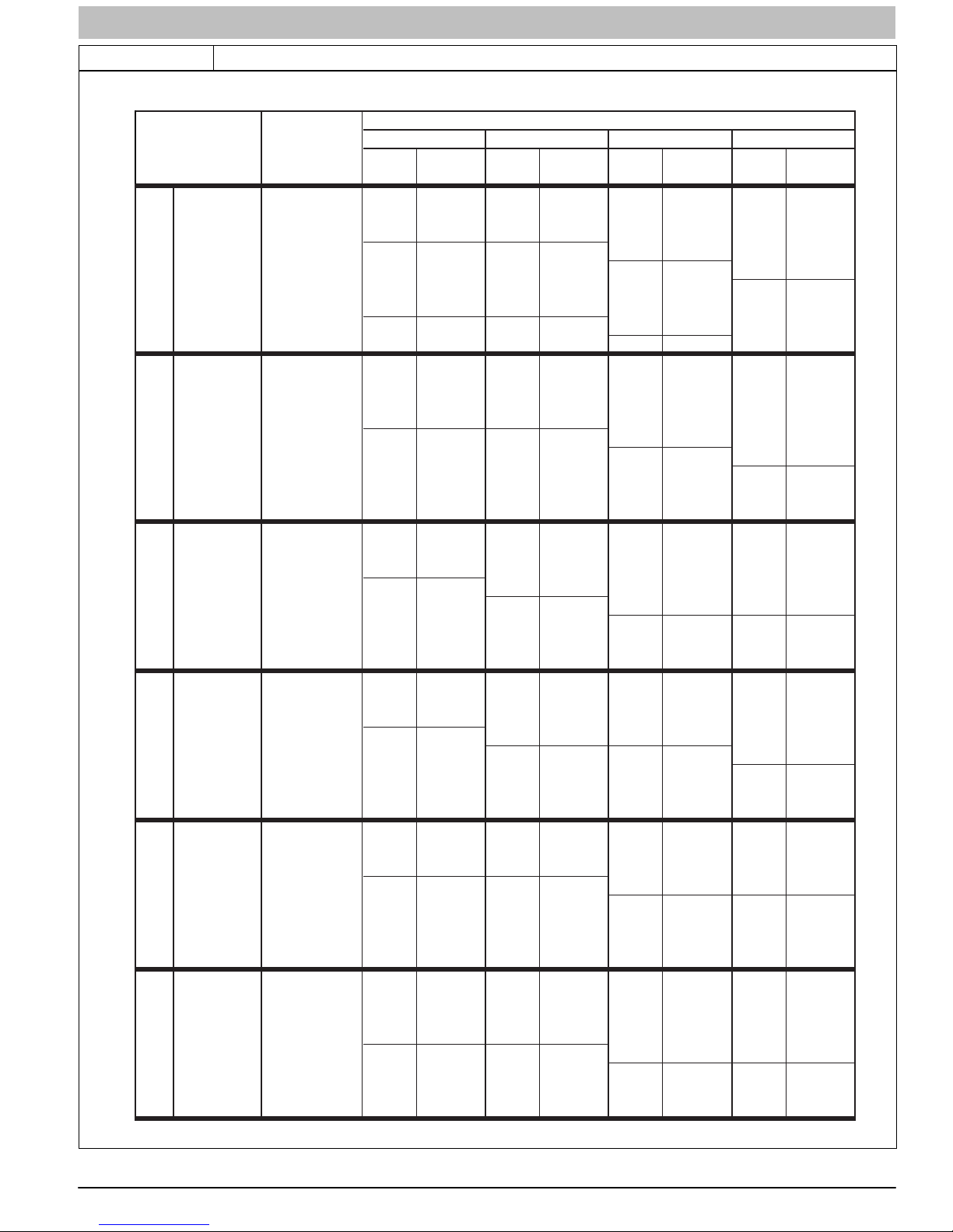
Table 3 Orifice Size and Manifold Pressure (in. w.c.) for Gas Input Rate − Single Stage
SINGLE-STAGE FURNACE
(TABULATED DATA BASED ON 20,000 BT UH PER BURNER, DERATED 2%/1000 FT (305M ) ABOVE SEA LEVEL)
ALTITUDE
RANGE
ft (m)
092543 3.6 43 3.7 43 3.8 42 3.2
(0) 950 43 3.4 43 3.5 43 3.6 43 3.7
to 1000 44 3.5 44 3.6 44 3.8 43 3.4
2000 1050 44 3.2 44 3.3 44 3.4 44 3.5
(610) 1075 45 3.7 45 3.8 44 3.3 44 3.4
U.S.A. 800 42 3.4 42 3.5 42 3.6 42 3.7
2001 (611) 825 43 3.8 42 3.3 42 3.4 42 3.5
to 850 43 3.6 43 3.7 42 3.2 42 3.3
3000 (914) 875 43 3.4 43 3.5 43 3.7 43 3.8
Canada 925 44 3.5 44 3.6 44 3.8 43 3.4
2001 (611) 950 44 3.3 44 3.4 44 3.6 44 3.7
U.S.A. and Canada
y
l
.S.A. On
U
y
l
n
.A. O
U.S
y U.S.A. Only U.S.A. and Canada
l
n
.A. O
U.S
to 975 44 3.2 44 3.3 44 3.4 44 3.5
4500 (1372) 1000 44 3.0 44 3.1 44 3.2 44 3.3
3001 800 43 3.8 42 3.2 42 3.3 42 3.4
(915) 825 43 3.6 43 3.7 43 3.8 42 3.2
to
4000 900 44 3.4 44 3.5 44 3.7 44 3.8
(1219) 925 44 3.2 44 3.4 44 3.5 44 3.6
4001 775 43 3.7 43 3.8 42 3.3 42 3.4
(1220) 800 43 3.5 43 3.6 43 3.7 43 3.8
to
5000 875 44 3.3 44 3.5 44 3.6 44 3.7
(1524) 900 44 3.2 44 3.3 44 3.4 44 3.5
5001 750 43 3.7 43 3.8 42 3.2 42 3.3
(1525) 775
to
6000 850 44 3.3 44 3.4 44 3.5 44 3.6
(1829) 875 44 3.1 44 3.2 44 3.3 44 3.4
6001 700 42 3.2 42 3.3 42 3.4 42 3.5
(1830) 725 43 3.6 43 3.7 43 3.8 42 3.3
to
7000 800 44 3.4 44 3.5 44 3.6 44 3.7
(2133) 825 44 3.2 44 3.3 44 3.4 44 3.5
HEATVALUE0.580.600.620.64
AT ALTIT UDE Orifice Manifold Orifice Manifold Orifice Manifold Orifice Manifold
(Btu/cu ft) No. Pressure No. Pressure No. Pressure No. Pressure
900 43 3.8 42 3.2 42 3.3 42 3.4
975 44 3.7 44 3.8 43 3.4 43 3.6
1025 44 3.3 44 3.5 44 3.6 44 3.7
1100 46 3.7 46 3.8 45 3.8 44 3.2
900 44 3.7 44 3.8 43 3.5 43 3.6
775 42 3.3 42 3.4 42 3.5 42 3.6
850 44 3.8 43 3.5 43 3.6 43 3.7
875 44 3.6 44 3.7 43 3.4 43 3.5
950 44 3.1 44 3.2 44 3.3 44 3.4
750 42 3.3 42 3.4 42 3.5 42 3.6
825 44 3.8 43 3.4 43 3.5 43 3.6
850 44 3.5 44 3.7 44 3.8 43 3.4
925 44 3.0 44 3.1 44 3.2 44 3.3
725 42 3.2 42 3.3 42 3.4 42 3.5
43 3.4 43 3.5 43 3.7 43 3.8
800 44 3.7 44 3.8 43 3.4 43 3.5
825 44 3.5 44 3.6 44 3.7 44 3.8
900 44 2.9 44 3.0 44 3.1 44 3.2
675 42 3.4 42 3.5 42 3.6 42 3.8
750 43 3.4 43 3.5 43 3.6 43 3.7
775 44 3.6 44 3.7 43 3.4 43 3.5
850 44 3.0 44 3.1 44 3.2 44 3.3
SAGLARUTANFOYTIVARGCIFICEPSSAG.GVA
440 04 4311 08 9
A11253A
Specifications subject to change without notice.
SERVICE AND TECHNICAL SUPPORT MANUAL Gas Furnace: (F/G)9MXE
Table 3 (CONT.) Orifice Size and Manifold Pressure (in. w.c.) for Gas Input Rate − Single Stage
SINGLE-STAGE FURNACE
(TABULATED DATA BASED ON 20,000 BTUH PER BURNER, DERATED 2%/1000 FT (305M) ABOVE SEA LEVEL)
ALTITUDE
RANGE
ft (m)
7001 675 43 3.8 42 3.2 42 3.3 42 3.4
(2134) 700 43 3.5 43 3.7 43 3.8 42 3.2
to
8000 775 44 3.3 44 3.4 44 3.5 44 3.7
(2438) 800 44 3.1 44 3.2 44 3.3 44 3.4
8001 650 43 3.8 42 3.2 42 3.3 42 3.4
(2439) 675 43 3.5 43 3.6 43 3.7 42 3.2
to
9000 750 44 3.3 44 3.4 44 3.5 44 3.6
(2743) 775 44 3.0 44 3.2 44 3.3 44 3.4
9001 600 42 3.3 42 3.4 42 3.6 42 3.7
(2744) 625 43 3.7 42 3.2 42 3.3 42 3.4
to
10000 700 44 3.4 44 3.5 44 3.7 44 3.8
U.S.A. Only U.S.A. OnlyU.S.A. Only
(3048) 725 44 3.2 44 3.3 44 3.4 44 3.5
* Orifice numbers shown in BOLD are factory-installed.
HEATVALUE0.580.600.620.64
AT ALTIT UDE Orifice Manifold Orifice Manifold Orifice Manifold Orifice Manifold
(Btu/cu ft) No. Pr essure No. Pressure No. Pressure No. Pres sure
650 42 3.4 42 3.5 42 3.6 42 3.7
725 44 3.8 43 3.4 43 3.5 43 3.6
750 44 3.5 44 3.7 44 3.8 43 3.4
825 44 2.9 44 3.0 44 3.1 44 3.2
625 42 3.4 42 3.5 42 3.6 42 3.7
700 44 3.7 43 3.4 43 3.5 43 3.6
725 44 3.5 44 3.6 44 3.7 44 3.8
650 43 3.5 43 3.6 43 3.7 43 3.8
675 44 3.7 44 3.8 43 3.4 43 3.5
SAGLARUTANFOYTIVARGCIFICEPSSAG.GVA
A11253B
Adjust Temperature Rise
NOTE: Blower door must be installed when taking temperature
rise reading. Leaving blower door off will result in incorrect
temperature measurements, due to possible changes in duct
static pressure and airflow.
!
CAUTION
FURNACE DAMAGE HAZARD
Failure to follow this caution may result in:
S Overheating the heat exchangers or condensing
flue gases in heat exchanger areas not designed
for condensate.
S Shortened furnace life.
S Component damage.
Temperature rise must be within limits specified on furnace
rating plate. Recommended operation is at midpoint of rise
range or slightly above.
Jumper R to W to check gas-heat temperature rise. Do not
exceed temperature rise ranges specified on unit rating plate.
This furnace must operate within the temperature rise ranges
specified on the furnace rating plate. Determine the air
temperature as follows:
1. Place duct thermometers in return and supply ducts as
close to furnace as possible. Be sure thermometers do
not “see” heat exchangers so that radiant heat does not
affect thermometer readings. This is particularly
important with straight−run ducts.
2. When thermometer readings stabilize, subtract return−air
temperature from supply−air temperature to determine
temperature rise.
10 440 04 4311 08
If the temperature rise is outside this range, check the
following:
1. Gas input rate.
2. Derate for altitude if applicable.
3. Return and supply ducts for excessive restrictions
causing static pressures greater than 0.50−in. w.c. (125
Pa)
4. Adjust temperature rise by adjusting blower speed.
S Increase blower speed to reduce temperature rise.
S Decrease blower speed to increase temperature rise.
ELECTRICAL OPERATION HAZARD
Failure to follow this warning could result in personal injury
or death.
Disconnect 115vac electrical power before changing speed
tap.
(Read following caution before changing taps.)
UNIT DAMAGE HAZARD
To avoid operating outside the rise range and avoid
component damage:
Refer to the Air Delivery Tables to determine which airflows
and settings are allowed for proper heating airflow. DO NOT
use the highlighted settings for heating airflow. The
highlighted settings are to be used for Cooling and
Continuous Fan ONLY.
Specifications subject to change without notice.
!
WARNING
!
CAUTION
 Loading...