

International Comfort Products G9MAE0601714A, G9MAE0602120A, G9MAE0801714A, G9MAE0802120A, G9MAE1002122A TECHNICAL MANUAL
...
SERVICE AND TECHNICAL
(
SUPPORT MANUAL
Modulating, Variable Speed Blower Motor
35” Tall, High Efficiency Condensing Gas Furnace
F/G)9MAE
Save this manual for future reference.
Safety Labeling and Signal Words
DANGER, WARNING, CAUTION, and NOTE
The signal words DANGER, WARNING,
CAUTION, and NOTE are used to identify levels of
hazard seriousness. The signal word DANGER is
only used on product labels to signify an immediate
hazard. The signal words WARNING, CAUTION,
and NOTE will be used on product labels and
throughout this manual and other manual that may
apply to the product.
DANGER − Immediate hazards which will result in
severe personal injury or death.
WARNING − Hazards or unsafe practices which
could result in severe personal injury or death.
CAUTION − Hazards or unsafe practices which
may result in minor personal injury or product or
property damage.
NOTE − Used to highlight suggestions which will
result in enhanced installation, reliability, or
operation.
Signal Words in Manuals
The signal word WARNING is used throughout
this manual in the following manner:
!
WARNING
The signal word CAUTION is used throughout
this manual in the following manner:
!
CAUTION
Signal Words on Product Labeling
Signal words are used in combination with
colors and/or pictures or product labels.
Safety−alert symbol
When you see this symbol on the unit and in
instructions or manuals, be alert to the
potential for personal injury.
TABLE OF CONTENTS
START−UP, ADJUSTMENT, AND SAFETY CHECK 4...........
SELECT SETUP SWITCH POSITIONS 4.....................
PRIME CONDENSATE TRAP WITH WATER 4.................
PURGE GAS LINES 5......................................
ADJUSTMENTS 5.........................................
ADJUST TEMPERATURE RISE 8............................
ADJUST BLOWER OFF DELAY (HEAT MODE) 9..............
ADJUST COOLING AIRFLOW 9.............................
ADJUST CONTINUOUS FAN AIRFLOW 9....................
ADJUST THERMOSTAT HEAT ANTICIPATOR 11...............
CHECK SAFETY CONTROLS 12.............................
CHECKLIST 12.............................................
COOLING AND HEATING AIR DELIVERY - CFM 17.............
SERVICE AND MAINTENANCE PROCEDURES 21.............
ELECTRICAL CONTROLS AND WIRING 21...................
CLEANING AND/OR REPLACING AIR FILTER 23..............
CLEANING BURNERS AND FLAME SENSOR 25...............
SERVICING HOT SURFACE IGNITER 26......................
FLUSHING COLLECTOR BOX AND DRAINAGE SYSTEM 27....
CLEANING CONDENSATE DRAIN AND TRAP 27..............
WINTERIZATION 28........................................
SERVICE LABEL 29.........................................
TROUBLESHOOTING CHART − FLOW CHART 31.............
TROUBLESHOOTING GUIDE − FLOW CHART 32..............
SEQUENCE OF OPERATION 34.............................
PARTS REPLACEMENT INFORMATION GUIDE 38.............
PRODUCT NOMENCLATURE 39.............................
MODELS
(F/G)9MAE0601714A
(F/G)9MAE0602120A
(F/G)9MAE0801714A
(F/G)9MAE0802120A
(F/G)9MAE1002122A
(F/G)9MAE1202422A
Use of the AHRI Certified TM Mark indicates a
manufacturer’s participation in the program.
For verification of certification for individual
products, go to www.ahridirectory.org .
Printed in U.S.A. 440 04 4700 00 Aug. 2012
SAFETY CONSIDERATIONS
Improper installation, adjustment, alteration, service,
maintenance, or use can cause explosion, fire, electrical shock,
or other conditions which may cause death, personal injury, or
property damage. Consult a qualified installer, service agency,
or your distributor or branch for information or assistance. The
qualified installer or agency must use factory−authorized kits or
accessories when modifying this product. Refer to the individual
instructions packaged with the kits or accessories when
installing.
Follow all safety codes. Wear safety glasses, protective clothing,
and work gloves. Use quenching cloth for brazing operations.
Have fire extinguisher available. Read these instructions
thoroughly and follow all warnings or cautions included in
literature and attached to the unit. Consult local building codes,
the current editions of the National Fuel Gas Code (NFCG)
NFPA 54/ANSI Z223.1, and the National Electrical Code (NEC)
NFPA 70.
In Canada refer to the current editions of the National standards
of Canada CAN/CSA−B149.1 and .2 Natural Gas and Propane
Installation Codes, and Canadian Electrical Code CSA C22.1.
Recognize safety information. This is the safety−alert symbol
. When you see this symbol on the unit and in instructions or
manuals, be alert to the potential for personal injury.
Understand these signal words; DANGER, WARNING, and
CAUTION. These words are used with the safety−alert symbol.
DANGER identifies the most serious hazards which will result in
severe personal injury or death. WARNING signifies hazards
which could result in personal injury or death. CAUTION is used
to identify unsafe practices which may result in minor personal
injury or product and property damage. NOTE is used to
highlight suggestions which will result in enhanced installation,
reliability, or operation.
!
WARNING
PERSONAL INJURY, AND/OR PROPERTY DAMAGE
HAZARD
Failure to carefully read and follow this warning could
result in equipment malfunction, property damage,
personal injury and/or death.
Installation or repairs made by unqualified persons could
result in equipment malfunction, property damage,
personal injury and/or death.
The information contained in this manual is intended for
use by a qualified service technician familiar with safety
procedures and equipped with proper tools and test
instruments.
Installation must conform with local building codes and
with the Natural Fuel Gas Code (NFCG) NFPA 54/ANSI
Z223.1, and National standards of Canada
CAN/CSA−B149.1 and .2 Natural Gas and Propane
Installation Codes.
!
ELECTRICAL SHOCK HAZARD
Failure to follow this warning could cause personal
injury or death.
Before performing service or maintenance operations
on unit, always turn off main power switch to unit and
install lockout tag. Unit may have more than one power
switch.
!
WARNING
WARNING
CARBON MONOXIDE POISONING AND FIRE
HAZARD
Failure to follow safety warnings could result in personal
injury, death, and/or property damage.
This furnace is not designed for use in mobile homes,
trailers or recreational vehicles.
!
CAUTION
CUT HAZARD
Failure to follow this caution may result in damage
personal injury.
Sheet metal parts may have sharp edges or burrs. Use
care and wear appropriate protective clothing, safety
glasses and gloves when handling parts and servicing
furnaces.
2
Specifications are subject to change without notice.
440 04 4700 00
SERVICE AND TECHNICAL SUPPORT MANUAL Gas Furnace: (F/G)9MAE
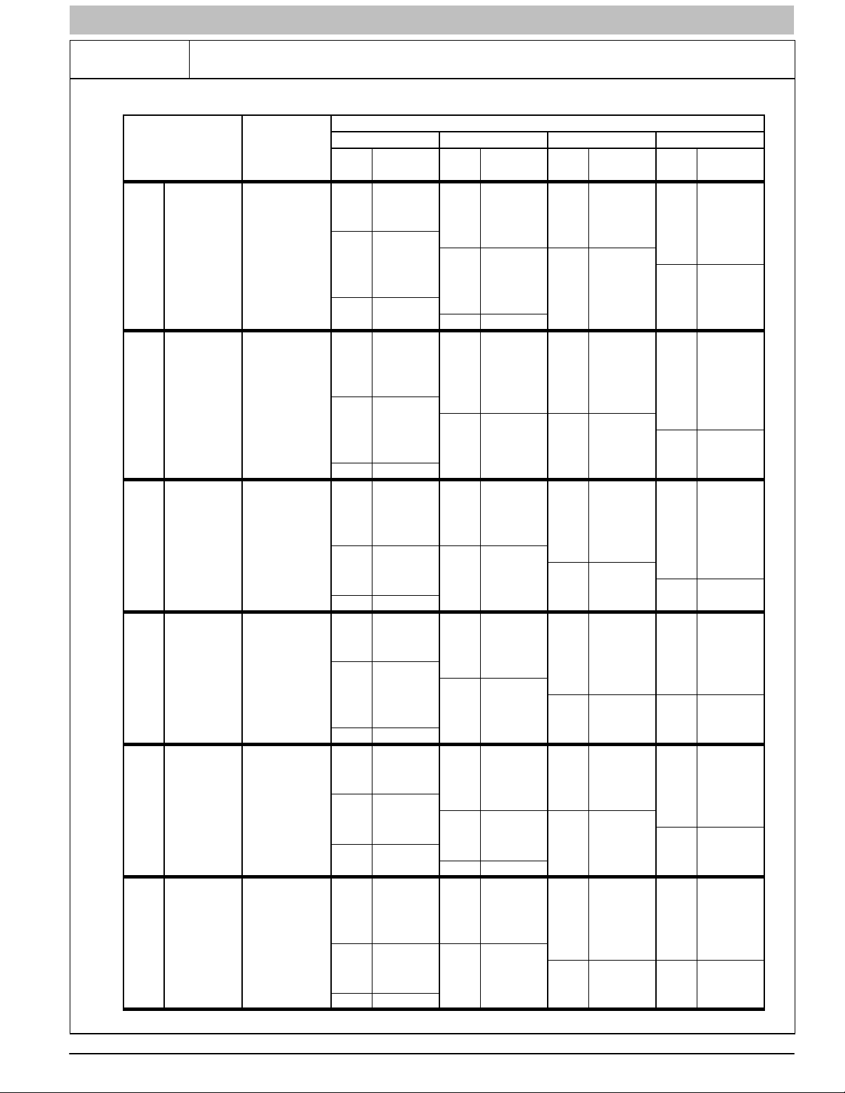
START−UP CHECK SHEET
For Variable Speed Models (F/G)9MAE
(This sheet is optional. Keep for future reference.)
Date of Start−Up:
Dealer Name:
Address:
City, State(Province), Zip or Postal Code:
Phone:
Owner Name:
Address:
City, State(Province), Zip or Postal Code:
Model Number:
Serial Number:
Setup Checks
Check the box when task is complete.
All Electrical Connections Tight?
Have hoses been relocated for furnace U/D/H
application?
Condensate Drain Connected?
Condensate Drain Trapped?
Manual Gas Shut−off Upstream of Furnace/Drip Leg
Heating Check
Measured Line Pressure During High Heat:
Measured Manifold Pressure: Max Heat
Min Heat
Temperature of Supply Air: Max Heat
Min Heat
Temperature of Return Air:
Temperature Rise (Supply − Return): Max Heat
Min Heat
In Rise Range (see furnace rating plate)?
Static Pressure (Ducts) High Heat: Supply
Return
Optional Check: CO?
CO2?
Cooling Check
Temperature of Supply Air:
Temperature of Return Air:
Temperature Difference:
Static Pressure (Ducts) Cooling: Supply
Return
Gas Valve turned ON?
Dealer Comments:
Type of Gas: Natural: Propane:
Filter Type and Size:
Shade in Final Furnace Settings Below:
Calculated Input (BTU) Rate: (See Checks and
Adjustments Section).
440 04 4700 00 3
Specifications subject to change without notice.

SERVICE AND TECHNICAL SUPPORT MANUAL Gas Furnace: (F/G)9MAE
START−UP, ADJUSTMENT, AND SAFETY
CHECK
General
1. Furnace must have a 115-v power supply properly
connected and grounded.
NOTE: Proper polarity must be maintained for 115-v wiring.
Control status indicator light flashes code 10 and furnace does
not operate if polarity is incorrect or if the furnace is not
grounded.
2. Thermostat wire connections at terminals R, W/W1, G,
Y/Y2, etc. must be made at 24-v terminal block on
furnace control. See communicating wall control
instructions for proper wiring of communicating controls.
3. Natural gas service pressure must not exceed 0.5 psig
(14- in. w.c., 350 Pa), but must be no less than 0.16 psig
(4.5-in. w.c., 1125 Pa).
4. Blower door must be in place to complete 115-v
electrical circuit and supply power to furnace.
!
CAUTION
UNIT OPERATION HAZARD
Failure to follow this caution may result in intermittent unit
operation or performance dissatisfaction.
These furnaces are equipped with a manual reset limit
switch in burner assembly. This switch opens and shuts off
power to the gas valve if an overheat condition (flame
rollout) occurs in the burner assembly/enclosure. Correct
inadequate combustion-air supply, improper gas pressure
setting, improper burner or gas orifice positioning, or
improper venting condition before resetting switch. DO
NOT jumper this switch.
Before operating furnace, check flame rollout manual reset
switch for continuity. If necessary, press button to reset switch.
EAC-1 terminal is energized whenever blower operates. HUM
terminal is only energized when blower is energized in heating.
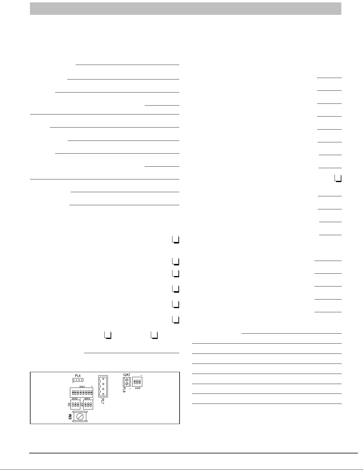
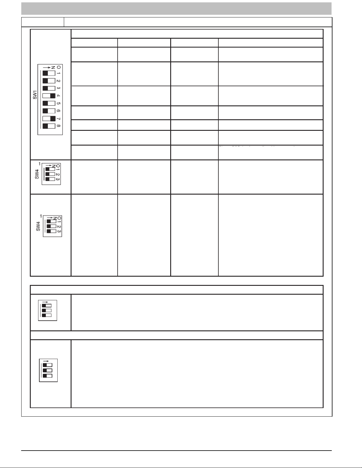
Select Setup Switch Positions
There are four sets of setup switches on the furnace control
board. These switches configure the furnace for correct
application requirement. They also select the airflow settings for
Air Conditioning and Continuous Fan airflows.
The Setup Switch locations are shown and described on
Figure 3, Figure 4, Table 3 and Table 6. The set up switches
are also shown on the unit wiring label.
Setup Switches (SW1)
The furnace control has eight setup switches that may be set to
meet the application requirements. Refer to Figure 4 and
Adjustments section for set up switch configurations.
To set these setup switches for the appropriate requirement:
1. Remove blower door.
2. Locate setup switches on furnace control.
3. Configure the set-up switches as necessary for the
application.
4. Replace blower door.
NOTE: If a bypass humidifier is used, setup switch SW1-3
(Min/Int Rise Adjust) should be in ON position. This
compensates for the increased temperature in return air
resulting from bypass.
NOTE: If modulating dampers are used, blower motor
automatically compensates for modulating dampers.
Air Conditioning (A/C) Setup Switches (SW2)
The air conditioning setup switches are used to match furnace
airflow to required cooling airflow or high stage cooling airflow
4 440 04 4700 00
Specifications subject to change without notice.
when a two−stage outdoor unit is used. Refer to Figure 4 and
the Adjustments section for set up switch configurations.
To set the desired cooling airflow:
1. Remove blower door.
2. Locate A/C setup switches on furnace control.
3. Determine air conditioning tonnage used.
4. Configure the switches for the required cooling airflow.
NOTE: Incorrect airflow caused by improper A/C switch setup
may cause condensate blow−off or a frozen indoor coil in the
cooling mode.
5. Replace blower door.
Continuous Fan (CF) Setup Switches (SW3)
The CF setup switches are used to select desired airflow when
thermostat is in continuous fan mode or to select low-cooling
airflow for two-speed cooling units. Refer to Figure 4 and the
Adjustments section for set up switch configurations.
1. Remove blower door.
2. Locate CF setup switches on furnace control.
3. Determine desired continuous fan airflow or low-cooling
airflow.
4. Configure the switches for the required continuous fan or
low−cooling airflow.
5. Replace blower door.
Additional Setup Switches (SW4)
The furnace control has three additional setup switches labeled
SW4.
Setup switch SW4-2 can be used to lock the furnace into
intermediate heat. When setup switch SW4-2 is ON it will over
ride setup switch SW1-2 if it is ON. SW4−3 is used to adjust
airflow. Refer to Figure 4 and the Adjustments section for set
up switch configurations.
1. Remove blower door.
2. Locate setup switch SW4 on furnace control.
3. Configure the switches for the required heat stages air
flow if necessary.
4. Replace blower door.
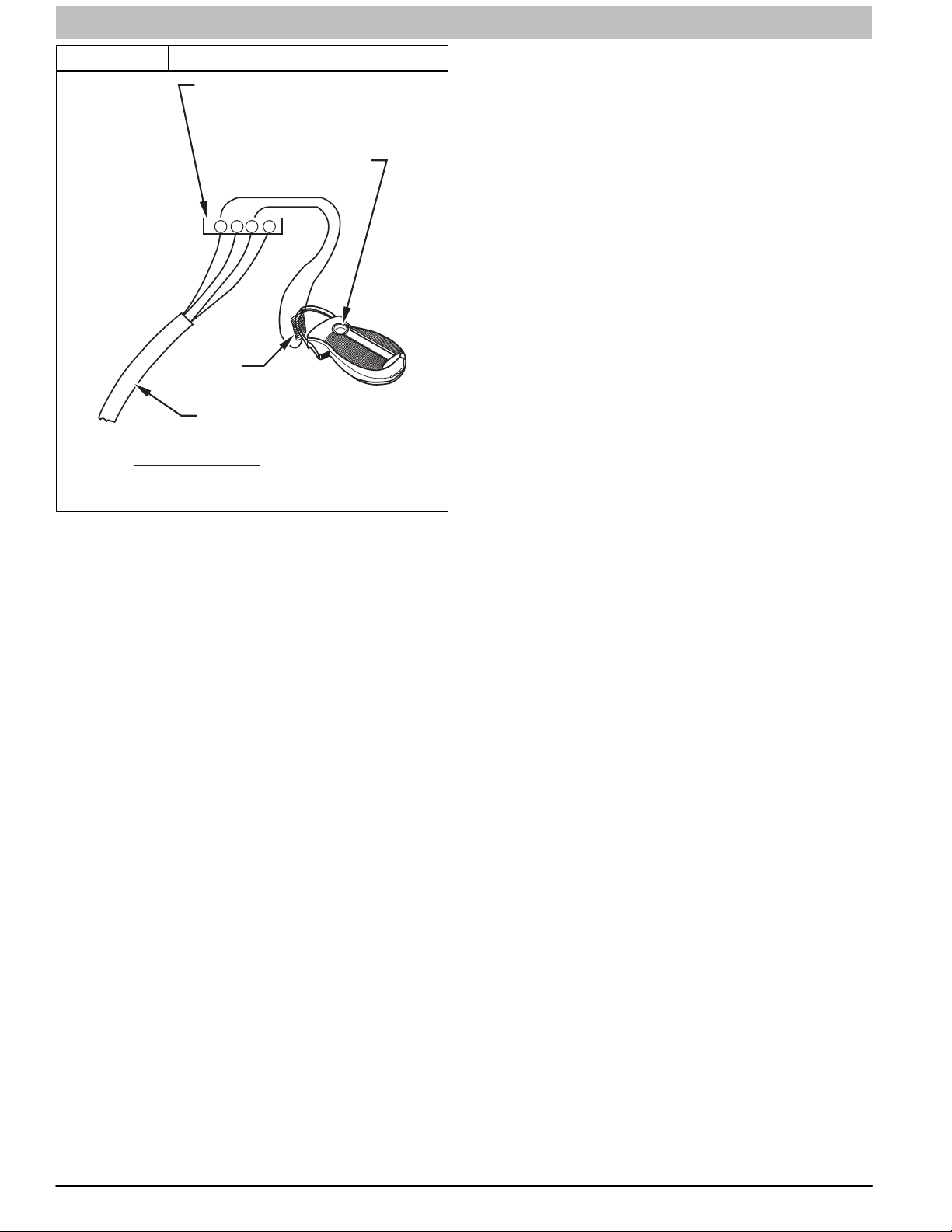
Prime Condensate Trap with Water
! WARNING
FIRE OR EXPLOSION HAZARD
Failure to follow these warnings could result in personal injury
or death.
Failure to use a properly configured trap or NOT
water-priming trap before operating furnace may allow
positive pressure vent gases to enter the structure through
drain tube. Vent gases contain carbon monoxide which is
tasteless and odorless.
!
CAUTION
UNIT OPERATION HAZARD
Failure to follow this caution may result in intermittent unit
operation or performance satisfaction.
Condensate trap must be PRIMED or proper draining may
not occur. The condensate trap has two internal
chambers which can ONLY be primed by pouring water
into the inducer drain side of condensate trap.
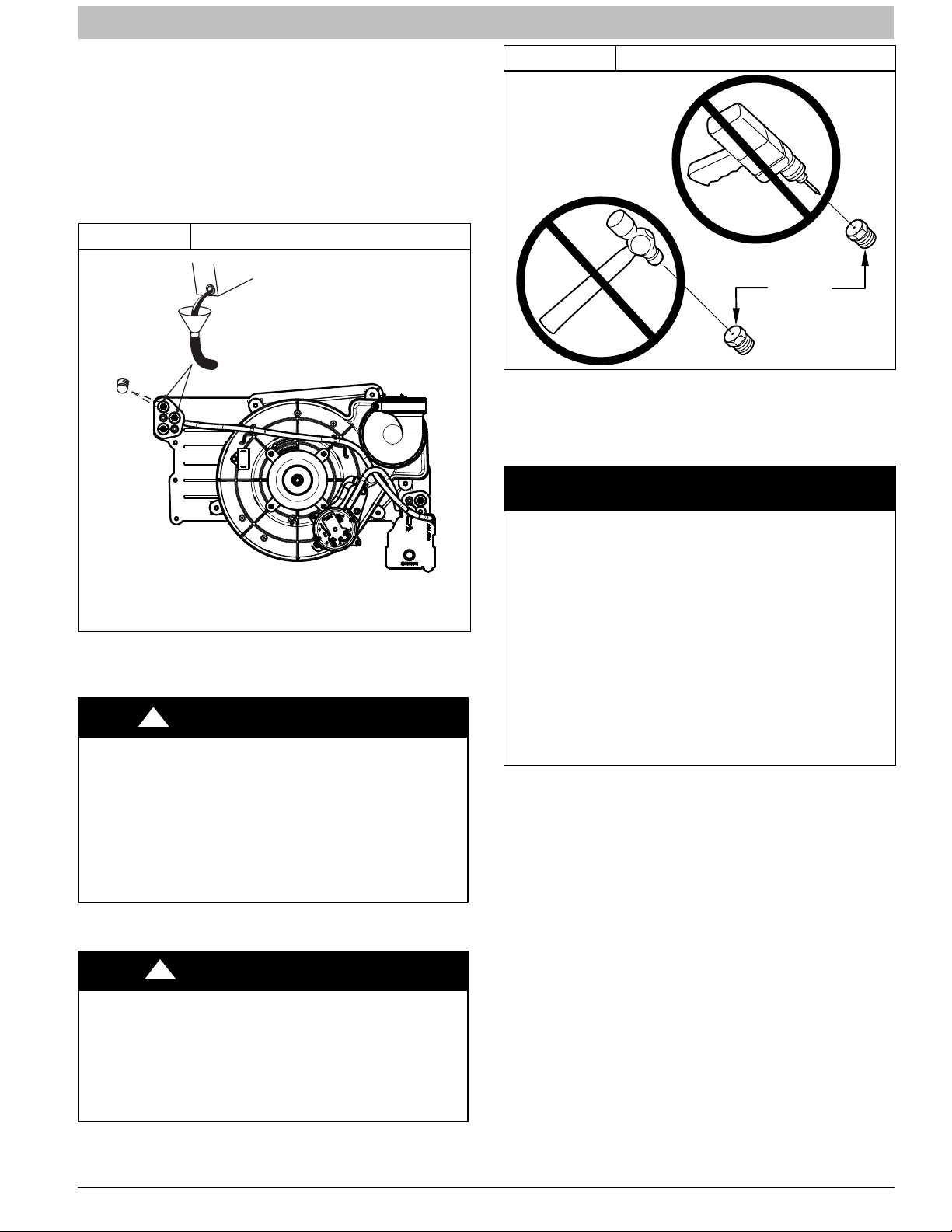
1. Remove upper and middle collector box drain plugs
opposite of the condensate trap. (See Figure 1)
2. Connect field-supplied 5/8-in. (16 mm) ID tube with
attached funnel (see Figure 1) to upper collector box
drain connection.
SERVICE AND TECHNICAL SUPPORT MANUAL Gas Furnace: (F/G)9MAE
3. Pour one quart (liter) of water into funnel/tube. Water
should run through collector box, overfill condensate
trap, and flow into open field drain.
4. Remove funnel; replace collector box drain plug.
5. Connect field-supplied 5/8-in. (16 mm) ID tube to middle
collector box drain port.
6. Pour one quart (liter) of water into funnel/tube. Water
should run through collector box, overfill condensate
trap, and flow into open field drain.
7. Remove funnel and tube from collector box and replace
collector box drain plug.
Figure 1 Priming Condensate Drain
Figure 2 Orifice Hole
BURNER
ORIFICE
A93059
For proper operation and long term reliability, the Furnace input
rate must be within +/− 2 percent of input rate on furnace rating
plate, or as adjusted for altitude.
The gas input rate on rating plate is for installations at altitudes
up to 2000 ft. (610 M).
NOTICE
Representative drawing only, some models may vary in appearance.
L11F065
Purge Gas Lines
If not previously done, purge the lines after all connections
have been made and check for leaks.
!
FIRE OR EXPLOSION HAZARD
Failure to follow this warning could result in personal
injury, death, and/or property damage.
Never purge a gas line into a combustion chamber. Never
test for gas leaks with an open flame. Use a commercially
available soap solution made specifically for the detection
of leaks to check all connections. A fire or explosion may
result causing property damage, personal injury or loss of
life.
WARNING
Adjustments
!
CAUTION
FURNACE DAMAGE HAZARD
Failure to follow this caution could result in reduced
furnace life.
DO NOT push or force gas valve adjusting screw. This
can result in damage to the adjustment screw resulting in
incorrect manifold pressure, which can result in a no heat
situation or shorten the life of the heat exchangers.
The NATURAL GAS manifold pressure adjustments in Table 4
and Table 5 compensate for BOTH altitude AND gas heating
value. DO NOT apply an additional de−rate factor to the
pressures shown in Table 4 or Table 5. The values in these
Tables are NOT referenced to sea level; they are
AS−MEASURED AT ALTITUDE.
The heating content of natural gas at altitude may already
provide for a reduction in capacity or the furnace. Be sure to
obtain the expected in−season gas heating value of the gas
from the gas supplier BEFORE making any adjustments for
capacity or altitude. Refer to Table 4 or Table 5. No
adjustments to the furnace may be necessary at altitude for
certain gas heating values.
Refer to the instructions provided in the factory-specified
LP/Propane conversion kit for instructions for setting gas
manifold pressures for LP/Propane applications.
In the USA, the input rating for altitudes above 2000 ft. (610 M)
must be reduced by 2 percent for each 1000 ft. (305 M) above
sea level. Refer to Table 1. The natural gas manifold pressures
in Table 4 and Table 5 adjust for BOTH altitude and natural gas
heating value.
In Canada, the input rating must be reduced by 5 percent for
altitudes of 2000 ft. (610 M) to 4500 ft. (1372 M) above sea
level. The natural gas manifold pressures in Table 4 and
Table 5 adjust for BOTH altitude and natural gas heating value.
NOTE: For Canadian altitudes of 200 to 4500 ft. (610 to 1372
M), use USA altitudes of 2001 to 3000 ft. (611 to 914 M) in
Table 4 and Table 5.
To adjust manifold pressure to obtain the proper input rate, first,
determine if the furnace has the correct orifice installed. At
higher altitudes or different gas heat contents, it may be
necessary to change the factory orifice to a different orifice.
Tables have been provided in the furnace Service and
Technical Manual to match the required orifice to the manifold
pressure to the heat content and specific gravity of the gas.
NOTE: There are two sets of manifold pressure tables. Use
Table 4 for all models EXCEPT *9MAE0602120 Btuh model.
Use Table 5 for only the *9MAE0602120 model.
440 04 4700 00 5
Specifications subject to change without notice.
SERVICE AND TECHNICAL SUPPORT MANUAL Gas Furnace: (F/G)9MAE
To do this:
1. Obtain average heat value (at installed altitude) from
local gas supplier.
2. Obtain average specific gravity from local gas supplier.
3. Find installation altitude range for your installation in the
manifold pressure tables. See Table 4 for the 20,000
Btuh Max−Heat/8,000/Btuh Min−Heat per burner models
or Table 5 for model *9MAE0602120 only (20,200 Btuh
Max−Heat/8,000 Btuh Min−Heat per burner).
4. Find closest natural gas heat value and specific gravity in
Table 4 or Table 5 depending on furnace gas input rate.
5. Follow heat value and specific gravity lines to point of
intersection to find orifice size and maximum and
minimum manifold pressure settings for proper operation.
6. Check and verify burner orifice size in furnace. Never
assume orifice size. NEVER ASSUME ORIFICE SIZE.
ALWAYS CHECK AND VERIFY.
NOTICE
If orifice hole appears damaged or it is suspected to have been
redrilled, check orifice hole with a numbered drill bit of correct
size. Never redrill an orifice. A burr−free and squarely aligned
orifice hole is essential for proper flame characteristics.
7. Replace orifice with correct size, if required by Table 4
or Table 5 depending on furnace gas input rate. Use only
factory−supplied orifices. See EXAMPLE 1.
EXAMPLE 1:
(See Table 4)
0 - 2000 ft. (0 - 609.6M) altitude
Heating value = 1050 Btu/cu ft.
Specific gravity = 0.62
Therefore: Orifice No. 44
(Furnace is shipped with No. 44 orifices. In this example, all
main burner orifices are the correct size and do not need to be
changed to obtain proper input rate.)
Manifold pressure: 3.4-in. w.c. (847 Pa) for Maximum heat,
.55-in. w.c. (349 Pa) for Minimum heat
NOTE: To convert gas manifold Table pressures to Pascals,
multiply the in.w.c. value by 249.1 Pa/in. w.c. (1 in. wc. = 249.1
Pa).
Table 1 Altitude Derate Multiplier for U.S.A.
ALTITUDE
FT. (M)
0–2000
(0−610)
2001–3000
(610−914)
3001–4000
(914−1219)
4001–5000
(1219−1524)
5001–6000
(1524−1829)
6001–7000
(1829−2134)
7001–8000
(2134−2438)
8001–9000
(2438−2743)
9001–10,000
(2743−3048)
* Derate multiplier factors are based on midpoint altitude for altitude range.
PERCENT
OF DERATE
0 1.00
4−6 0.95
6−8 0.93
8−10 0.91
10−12 0.89
12−14 0.87
14−16 0.85
16−18 0.83
18−20 0.81
DERATE MULTIPLIER
FACTOR*
NOTE: For Canadian altitudes of 2000 to 4500 ft. (610 to
1372 M), use USA altitudes of 2001 to 3000 ft. (610 to 914
M).
Check Inlet Gas Pressure
The inlet gas pressure must be checked with the furnace
operating in maximum heat. This is necessary to make sure the
inlet gas pressure does not fall below the minimum pressure of
4.5−in. w.c. for natural gas. The maximum inlet gas pressure is
13.6−in. w.c. If the inlet pressure is too low, you will not be able
to adjust the manifold pressure to obtain the proper input rate.
To check the inlet gas pressure:
1. Make sure the gas supply is turned off to the furnace and
at the electric switch on the gas valve.
2. Remove the 1/8 inch NPT plug from the inlet pressure
tap on the gas valve.
3. Connect a manometer to the inlet pressure tap on gas
valve.
4. Turn on furnace power supply.
5. Turn gas supply manual shutoff valve to ON position.
6. Turn furnace gas valve switch to ON position.
7. Jumper the R to W/W1 and W2 thermostat connections
at the furnace control board.
8. When main burners ignite, confirm inlet gas pressure is
Between 4.5−in. w.c. and 13.6−in. w.c.
9. Remove jumper across thermostat connections to
terminate call for heat. Wait until the blower off delay is
completed.
10. Turn furnace gas valve electric switch to OFF position.
11. Turn gas supply manual shutoff valve to OFF position.
12. Turn off furnace power supply.
13. Remove manometer from the inlet pressure tap of the
gas valve.
!
FIRE HAZARD
Failure to follow this warning could result in personal injury,
death, and/or property damage.
Re−install manifold pressure tap plug in gas valve to
prevent gas leak.
14. Apply pipe dope sparingly to end of inlet gas pipe plug
and re−install in the gas valve.
WARNING
Adjust Manifold Pressure−Maximum Heat
The modulating furnace manifold pressure is set at two points.
The first point is Maximum Heat.
The second point is Minimum Heat. Do not adjust Intermediate
Heat manifold pressure. Intermediate Heat manifold pressure is
checked as part of the temperature rise, but is not adjustable.
Always adjust Maximum Heat first, then Minimum Heat.
NOTICE
DO NOT set maximum heat manifold pressure less than 3.2−in.
w.c. (947 Pa) for natural gas. If required manifold pressure is
outside this range, change main burner orifices to obtain
manifold pressure in this range.
To adjust manifold pressure to obtain input rate for Maximum
Heat:
1. Make sure the gas supply is turned off to the furnace and
at the electric switch on the gas valve.
6 440 04 4700 00
Specifications subject to change without notice.
SERVICE AND TECHNICAL SUPPORT MANUAL Gas Furnace: (F/G)9MAE
2. Remove the 1/8 inch NPT plug from the outlet pressure
tap on the gas valve.
3. Connect a manometer to the outlet pressure tap on gas
valve.
4. Turn on furnace power supply.
5. Turn gas supply manual shutoff valve to ON position.
6. Turn furnace gas valve switch to ON position.
7. Jumper the R to W/W1 and W2 thermostat connections
at the furnace control board.
8. After the main burners ignite and the blower starts,
confirm Maximum Heat manifold pressure is correct,
based on the manifold pressure tables in the installation
instructions.
9. To adjust the Maximum Heat manifold pressure, slowly
turn adjusting screw counterclockwise to decrease
manifold pressure or clockwise to increase manifold
pressure. Turn adjustment no more than one click per
second until you obtain the required manifold pressure.
10. Main burner flame should be clear blue, almost
transparent.
11. After adjusting the Maximum Heat manifold pressure,
remove jumpers across thermostat connections to
terminate the call for heat.
12. Wait for blower off-delay to finish then reset 115-v power
to furnace.
Adjust Manifold Pressure−Minimum Heat
To adjust manifold pressure to obtain input rate for Minimum
Heat:
1. Turn SW1−2 ON at the furnace control. Set up switch
SW4−2 must be OFF.
2. Jumper R and W/W1 thermostat connections on control
to start furnace.
3. After the main burners ignite and the blower starts,
confirm Minimum Heat manifold pressure is correct,
based on the manifold pressure tables in the installation
instructions.
4. To adjust the Minimum Heat manifold pressure, slowly
turn adjusting screw counterclockwise (out) to decrease
manifold pressure or clockwise (in) to increase manifold
pressure. Turn adjustment no more than one click per
second until you obtain the required manifold pressure.
5. After adjusting the manifold pressure, remove jumpers
across thermostat connections to terminate the call for
heat. Wait until the blower off delay is completed.
6. Move setup switch SW1-2 to the OFF position.
7. Turn gas supply manual shutoff valve to OFF position.
8. Turn off furnace power supply.
!
FIRE HAZARD
Failure to follow this warning could result in personal injury,
death, and/or property damage.
Re−install manifold pressure tap plug in gas valve to
prevent gas leak.
9. Remove manometer from the inlet pressure tap of the
gas valve.
10. Apply pipe dope sparingly to end of inlet gas pipe plug
and re-install in the gas valve.
WARNING
11. Re-install cap over adjustment screw on the top of the
gas valve.
Clocking the Meter
Verify natural gas input rate by clocking meter.
NOTE: Contact your HVAC distributor or gas supplier for metric
gas meter Tables, if required.
1. Turn off all other gas appliances and pilots served by the
meter.
2. Move setup switches SW1-2 to ON position and SW4-2
to OFF. This keeps furnace locked in Minimum Heat
operation when only W/W1 is energized or Maximum
Heat operation when R to W/W1 and W2 are jumpered.
3. Jumper R to W/W1 and W2. Run furnace for 3 minutes in
Maximum Heat operation.
4. Measure time (in sec) for gas meter to complete one
revolution and note reading. The 2 or 5 cubic feet dial
provides a more accurate measurement of gas flow.
5. Refer to Table 3 for cubic ft. of gas per hr. Multiply gas
rate cu ft./hr by heating value (Btuh/cu ft.) to obtain input
rate.
6. If clocked rate does not match required input from Step
5, increase manifold pressure to increase input or
decrease manifold pressure to decrease input. Repeat
steps 3 through 5 until correct maximum heat input is
achieved.
7. Remove jumpers across thermostat connections to
terminate the call for heat. Wait until the blower off delay
is completed then reset 115-v power to furnace.
8. Jumper R and W/W1 thermostat connections on control
to start furnace.
NOTE: Setup switches SW1-2 must be ON and SW4-2 must
be OFF. This keeps furnace locked in minimum heat operation
when R to W/W1 is energized. Repeat items 3 through 6 for
minimum heat operation until minimum heat input is achieved
9. Restore furnace to normal operating condition.
10. Remove jumpers across thermostat connections to
terminate the call for heat. Wait until the blower off delay
is completed.
11. Disconnect 115 VAC power to furnace.
12. Turn gas valve ON/OFF switch to OFF.
13. Remove water column manometer or similar device from
manifold pressure tap (if still connected).
!
FIRE HAZARD
Failure to follow this warning could result in personal injury,
death, and/or property damage.
Re−install manifold pressure tap plug in gas valve to
prevent gas leak.
14. Replace manifold pressure tap plug to gas valve.
15. Turn gas valve ON/OFF switch to ON.
16. Move setup SW1-2 on furnace control to position
required for attached thermostat (OFF for single-stage
thermostats, ON for two-stage thermostats).
17. Check for gas leaks and verify furnace operation.
WARNING
440 04 4700 00 7
Specifications subject to change without notice.
SERVICE AND TECHNICAL SUPPORT MANUAL Gas Furnace: (F/G)9MAE
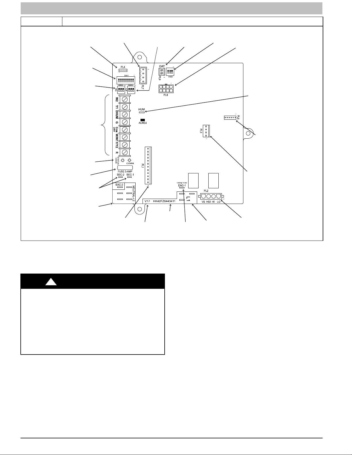
Figure 3 Variable Speed Furnace Control for ECM Blower Motor (Modulating)
MODEL PLUG
CONNECTOR
SW1 SETUP
SWITCHES AND
BLOWER OFFï
DELAY
AIR CONDITIONING
(A/C) AIRFLOW
SETUP SWITCHES
24ïV THERMOSTAT
TERMINALS
STATUS AND COMM
LED LIGHTS
3ïAMP FUSE
TRANSFORMER 24ïVAC
CONNECTIONS
COMMUNICATION
CONNECTOR
CONTINUOUS FAN
(CF) AIRFLOW
SETUP SWITCHES
OUTDOOR
IR TEMP
CONNECTOR
SW4 SETUP
SWITCHES
PL8 ï MODULATING
GAS VALVE
CONNECTOR
HUMIDIFIER
TERMINAL (24AVAC
0.5 AMP MAX.
UPGRADE
CONNECTOR
(FACTORY
PL3 ć ECM BLOWER
HARNESS
CONNECTOR
ï
FLASH
ONLY)
115ïVAC (L2) NEUTRAL
CONNECTIONS
PART NUMBER AND
PL1 ć LOW VOLTAGE MAIN
HARNESS CONNECTOR
SOFTWARE
VERSION
DATE CODE WWYY
(115ïVAC 1.0 AMP MAX.)
Adjust Temperature Rise
NOTE: Blower door must be installed when taking temperature
rise reading. Leaving blower door off will result in incorrect
temperature measurements.
EACï1 TERMINAL
115ïVAC (L1) LINE
VOLTAGE CONNECTIONS
NOTE: Temperature rise can be determined for Minimum Heat,
Intermediate Heat and Maximum Heat operation by locking the
furnace in each mode of operation. The mode of operation is
based on the position of Set-up switch SW1-2 and SW4-2 on
the furnace control board.
PL2 ć HOT SURFACE
IGNITER & INDUCER
MOTOR CONNECTOR
The furnace is capable of automatically providing proper airflow
!
CAUTION
FURNACE DAMAGE HAZARD
Failure to follow this caution may result in:
S Overheating the heat exchangers or condensing
flue gases in heat exchanger areas not designed
for condensate
S Shortened furnace life
S Component damage
Temperature rise must be within limits specified on furnace
rating plate. Recommended operation is at midpoint of rise
range or slightly above.
Furnace must operate within ranges of temperature rise
specified on the furnace rating plate. When setup switch SW1-4
is ON, operation will be near the high end of the rise range for
improved comfort.
Determine air temperature rise as follows:
1. Place thermometers in return and supply ducts as near
furnace as possible. Be sure thermometers do not see
heat exchanger so that radiant heat does not affect
readings. This practice is particularly important with
straight-run ducts.
2. When thermometer readings stabilize, subtract return-air
temperature from supply-air temperature to determine air
temperature rise.
8 440 04 4700 00
Specifications subject to change without notice.
to maintain the temperature rise within the range specified on
furnace rating plate. If temperature rise is outside this range,
proceed as follows:
a. Check gas input for Minimum, Intermediate, and
Maximum heat operation.
b. Check derate for altitude if applicable.
c. Check all return and supply ducts for excessive
restrictions causing static pressure greater than 0.5-in.
w.c.
d. Ensure Min/Int Rise Adjust switch SW1−3 on furnace
control is in ON position when a bypass humidifier is
used. (See Figure 3 for switch location.)
e. Check Troubleshooting Guide for Variable−Speed Step
Modulating Condensing Furnaces.
f. Verify correct model plug is installed.
To lock the furnace in Minimum Heat:
1. Turn SW1−2 ON at the furnace control. Set up switch
SW4−2 must be OFF.
2. Connect a jumper across R and W/W1 at the thermostat
terminals at the furnace control.
3. Allow the burners to ignite and the blower to turn on.
4. Allow the supply temperature to stabilize and verify the
proper rise range.
If the temperature rise is too high or too low in Minimum
Heat:
1. Remove jumpers from R and W/W1.
L11F091
SERVICE AND TECHNICAL SUPPORT MANUAL Gas Furnace: (F/G)9MAE
2. Wait until the blower off delay is completed.
3. Turn 115 VAC power off.
4. Check the position of Set up switch SW1−3. When set to
ON, airflow is raised 18% for Minimum Heat and for
Intermediate Heat. Factory default position is OFF.
5. Turn 115 VAC power on.
6. Re−check Minimum Heat Temperature Rise.
To lock the furnace in Intermediate Heat:
1. Turn SW1−2 OFF and SW4−2 ON at the furnace control.
2. Connect a jumper across R and W/W1 at the thermostat
terminals at the furnace control.
3. Allow the burners to ignite and the blower to turn on.
4. Allow the supply temperature to stabilize and verify the
proper rise range.
If the temperature rise is too high or too low in Intermediate
Heat:
1. Remove jumpers from R and W/W1.
2. Wait until the blower off delay is completed.
3. Turn 115 VAC power off.
4. Check the position of Set up switch SW1−3. When set to
ON, airflow is raised 18% for Minimum Heat and for
Intermediate Heat. Factory default position is OFF.
5. Turn 115 VAC power on.
6. Re−check Intermediate Heat Temperature Rise .
To lock the furnace in Maximum Heat:
1. Connect a jumper across R and W/W1 and W2 at the
thermostat terminals at the furnace control.
2. Allow the burners to ignite and the blower to turn on.
3. Allow the supply temperature to stabilize and verify the
proper rise range.
If the temperature rise is too high or too low in Maximum
Heat:
1. Remove jumpers from R and W/W1 and W2.
2. Wait until the blower off delay is completed.
3. Turn 115 VAC power off.
4. Check the position of Set up switch SW1−4. When set to
OFF, and SW1−3 is set to OFF, airflow is raised 10% for
Minimum Heat, 7.5% for Intermediate Heat and 17.5%
for Maximum Heat. Factory default position is ON. If
SW1−3 is ON and SW1−4 is OFF, airflow is raised 18%
for Minimum and Intermediate heat and 10% for
Maximum Heat.
5. Turn 115 VAC power on.
6. Re−check Maximum Heat Temperature Rise.
After the temperature rise has been verified:
1. Remove jumpers from thermostat terminals.
2. Allow the blower off delay to complete.
3. Turn Set up switches SW1−2 and SW4−2 to the OFF
position unless two−stage thermostat operation is
desired. (See Figure 4)
4. Proceed to “Adjust Blower Off Delay” or install blower
door if complete.
!
FIRE HAZARD
Failure to follow this warning could result in personal injury,
death, and/or property damage.
Reinstall manifold pressure tap plug in gas valve to
prevent gas leak.
WARNING
Adjust Blower Off Delay (Heat Mode)
a. Remove blower door if installed.
b. Turn Dip switch SW−7 or SW−8 ON or OFF for
desired blower off delay. (See Table 2, Figure 3 and
Figure 4)
Table 2 Blower Speed Taps
DESIRED HEATING MODE
BLOWER OFF DELAY
(SEC.)
90 OFF OFF
120 ON OFF
150 OFF ON
180 ON ON
SETUP SWITCH POSITION
SW1-7 SW1-8
Adjust Cooling Airflow − High−Speed and
Low−Speed Cooling
The ECM blower can be adjusted for a range of airflows for
low−speed or high−speed cooling. See Table 3 − Airflow
Switch Table, Table 6 − Air Delivery − CFM (with Filter) and
Figure 4. Furnace Setup Switches and Descriptions.
Depending on the model size, the cooling airflow can be
adjusted from 1.5 tons to 6 tons of nominal cooling based on
350 CFM ton.
NOTE: 6 ton airflow will truncate at 2200 CFM on applicable
models.
The high−speed or single−speed cooling airflow is adjusted by
turning setup switches SW2−1, SW2−2 and SW2−3 either ON
or OFF. Select the required airflow from Table 6. Table 6 is
based on 350 CFM per ton. For other CFM per ton setup switch
selections, see Table 3, Figure 4 and Figure 15.
The Continuous Fan airflow selection via setup switches SW3
is also the airflow for low−speed cooling when the furnace is
used with a two−speed cooling or heat pump unit. Adjust the
Continuous Fan CFM setup switches SW3 to match the airflow
required for low−speed cooling. Select the required airflow from
Table 6 and Figure 4.
NOTE: The airflow selected via SW3 (low−speed cooling
airflow) cannot exceed the airflow selected via SW2
(high−speed cooling airflow). For other CFM per ton setup
switch selections, see Table 3 and Figure 4.
NOTE: The airflow settings for SW2 and SW3 selections are
the same, EXCEPT for the default values. (See Table 6)
For a complete explanation of cooling airflow, refer to the
section titled “Sequence of Operation.”
Adjust Continuous Fan Airflow/Low Speed
Cooling Airflow
NOTE: When the furnace is used with a two−speed cooling or
heat pump unit, the airflow selected for Continuous Fan via
setup switch SW3 will also be the airflow used for low−speed
cooling, and vice versa.
NOTE: When the furnace is used with a two−speed cooling or
heat pump unit, adjust the Continuous Fan CFM setup
switches SW3 to match the airflow required for low−speed
cooling.
Select the required Continuous Fan airflow using setup
switches SW3 as shown in Table 3, Figure 4 and Figure 15.
!
CAUTION
FURNACE OVERHEATING HAZARD
Failure to follow this caution may result in reduced furnace
life.
Recheck temperature rise. It must be within limits specified
on the rating plate. Recommended operation is at the
mid−point of rise range or slightly above.
440 04 4700 00 9
Specifications subject to change without notice.
SERVICE AND TECHNICAL SUPPORT MANUAL Gas Furnace: (F/G)9MAE
T
Bl
Off Del
Allows additional CFM per ton selections when used with SW
p
p
Figure 4 Furnace Setup Switch Description
Furnace Setup Switch Description
ESU FO NOITPIRCSEDNOITISOP LAMRONEMAN HCTIWSHCTIWS PUTES
SW1-1 Status Code Recovery OFF
Minimum Heat Only
SW1-2
SW1-3
SW1-4
SW1-5 CFM per ton adjust OFF
SW1-6 Component Self Test OFF
SW1-7 & SW1-8 Blower OFF delay ON or OFF
SW4-2
(Adaptive Heat Mode
when SW1-2 and SW4-2
are OFF)
Min/Int Heat Rise
Adjustment
Comfort/Efficiency
Adjustment
Intermediate Heat
Only
(Adaptive Heat Mode
when both SW1-2 and
SW4-2 are OFF)
OFF
OFF
ON
OFF
Turn ON to retrieve up to 7 stored status codes for
troubleshooting assistance when R thermostat lead is
disconnected.
When SW1-2 and SW4-2 are OFF allows Modulating operation
with a single stage thermostat. Turn ON SW1-2 when using
two-stage thermostat to allow Minimum Heat operation when
R to W/W1 closed and a Maximum heat operation when R to
W/W1 and R to W2 close.
urn ON to increase Minimum Heat and Intermediate Heat
airflow by 18 percent. This compensates for increased return
air temperature caused with bypass humidifier. This also
increases the Intermediate Heat inducer speed 15 percent.
Turn ON to decrease Minimum heat airflow by 10 percent,
Intermediate Heat airflow 7.5 percent and Maximum Heat
airflow 17.5 percent for maximum comfort.
Turn ON for 400 CFM per ton, Turn OFF for 350 CFM per ton.
See also SW4.
Turn ON to initiate Component Self Test for troubleshooting
assistance when R thermostat lead is disconnected. Turn
OFF when Self Test is completed.
ower
seconds. See table in Adjustments section or refer to unit
wiring diagram.
When SW1-2 and SW4-2 are OFF allows Modulating operation
with a single stage thermostat. Turn ON SW4-2 when using
two-stage thermostat to allow Intermediate Heat operation
when R to W/W1 closed and a Maximum heat operation when
R to W/W1 and R to W2 close.
ay time – adjustable 90 seconds to 180
1
SW2
1
SW3
AC
CF
1-5
325 CFM per ton (nominal) when SW 4-3 ON and SW 1-5 OFF
350 CFM per ton (nominal) when SW 4-3 OFF and SW 1-5 OFF
SW4-3
O
N
1
2
3
O
N
1
2
3
SW 2, AC (Cooling Airflow) SETUP SWITCHES
The AC setup switch selects desired cooling or high stage cooling (two stage units) airflow.
See Cooling Air Delivery Tables for specific switch settings
SW 3, CF (Continuous Fan) SETUP SWITCHES
The CF setup switch selects desired Continuous Fan Airflow
The CF switch position is the Low Cooling airflow selection for two stage cooling units.
SW 3 cannot be set for airflow higher than SW 2
See Continuous Fan Air Delivery Tables for specific switch settings
CFM per ton Adjust
AIR CONDITIONING (A/C) SETUP SWITCHES
CONTINUOUS FAN (CF) SETUP SWITCHES
OFF
370 CFM per ton (nominal) when SW4-3 ON and SW 1-5 ON
400 CFM per ton (nominal) when SW 1-5 ON and SW 4-3 OFF
See Air Delivery Tables for model specific CFM vs. static
ressure
10 440 04 4700 00
A11575
Specifications subject to change without notice.
SERVICE AND TECHNICAL SUPPORT MANUAL Gas Furnace: (F/G)9MAE
321N321
N 321N 321N 321N 321N 321N 321N 321N
321N321
N 321N 321N 321N 321N 321N 321N 321N
321N321
N 321N 321N 321N 321N 321N 321N 321N
321N321
N 321N 321N 321N 321N 321N 321N 321N
060-14
080-14
060-20
080-20
100-22
120-22
1860
1860
1116
1116
976
976
1200
1200
1860
2100
1488
1860
2100
930
744
930
1116
1302
1488
744
744
930
1116
1302
1860
744
744
930
1116
1302
1488
1860
1860
1860
744
744
930
1116
1302
1488
1860
1860
1302
1302
1302
558
558
744
930
1116
1302
558
558
744
930
1116
1302
1302
1627
1953
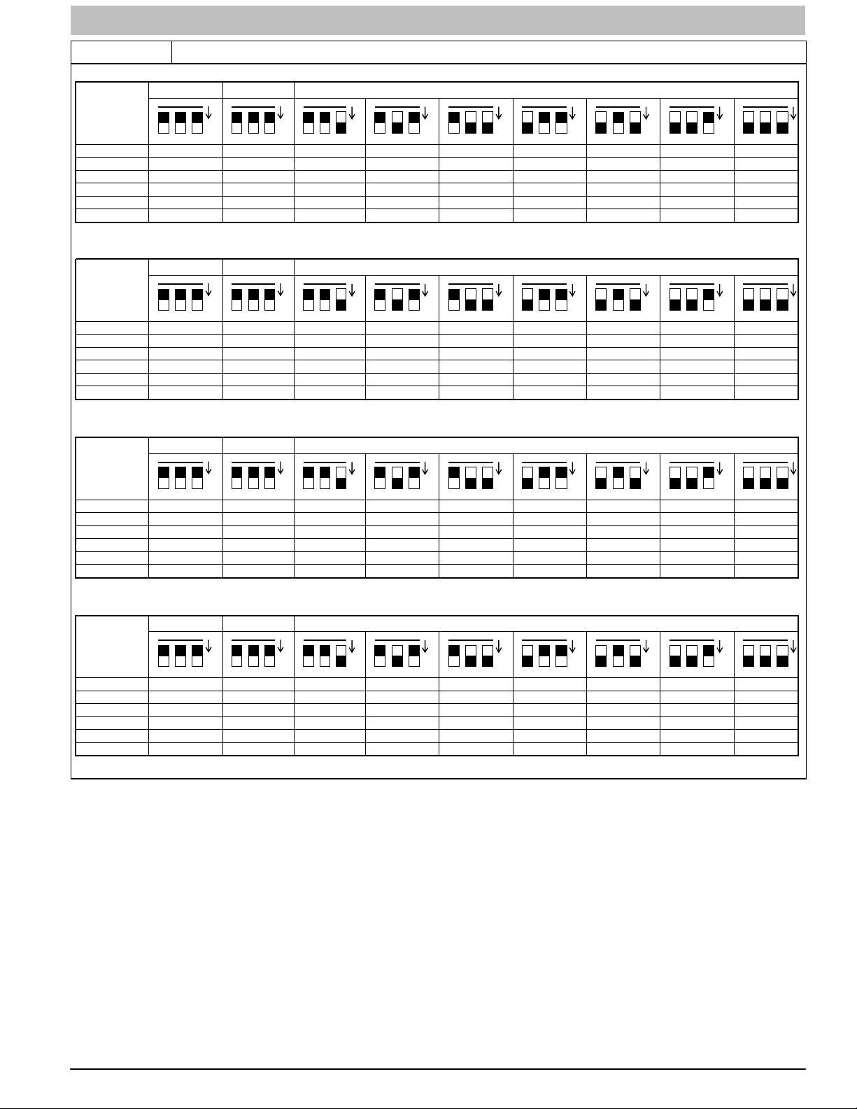
NOMINAL AIRFLOW BASED ON 370 CFM/TON (SW1-5 = ON, SW4-3 = ON)
Model Size
SW2 Clg Defa ult
SW3 CF Default
COOLING (SW2) AND CONTINUOUS FAN (SW3) AIRFLOW: SET-UP SWITCH POSITIONS
1302
1627
1953
1627
814
651
814
976
1139
1302
1627
651
651
814
976
1139
1627
651
651
814
976
1139
1302
1627
1627
1627
651
651
814
976
1139
1302
1627
1627
1139
1139
1139
488
488
651
814
976
1139
488
488
651
814
976
1139
1139
2000
2100
NOMINAL AIRFLOW BASED ON 325 CFM/TON (SW1-5 = OFF, SW4-3 = ON)
Model Size
SW2 Clg Defa ult
SW3 CF Default
COOLING (SW2) AND CONTINUOUS FAN (SW3) AIRFLOW: SET-UP SWITCH POSITIONS
1600
2000
2100
2000
1000
800
1000
1200
1400
1600
2000
800
800
1000
1200
1400
2000
800
800
1000
1200
1400
1600
2000
2000
2000
800
800
1000
1200
1400
1600
2000
2000
1400
1400
1400
600
600
800
1000
1200
1400
600
600
800
1000
1200
1400
1400
1400
1750
2100
NOMINAL AIRFLOW BASED ON 400 CFM/TON (SW1-5 = ON, SW4-3 = OFF)
Model Size
SW2 Clg Defa ult
SW3 CF Default
COOLING (SW2) AND CONTINUOUS FAN (SW3) AIRFLOW: SET-UP SWITCH POSITIONS
1750
875
700
875
1050
1225
1750
700
700
875
1050
1225
1400
1750
2100
1750
700
700
875
1050
1225
1400
1750
1750
1750
700
700
875
1050
1225
1400
1750
1750
1050
525
525
700
875
1050
1225
1225
1225
NOMINAL AIRFLOW BASED ON 350 CFM/TON (Factory Default - SW1-5 = OFF, SW4-3 = OFF)
Model Size
SW2 Clg Defa ult
SW3 CF Default
COOLING (SW2) AND CONTINUOUS FAN (SW3) AIRFLOW: SET-UP SWITCH POSITIONS
1050
525
525
700
875
1050
1225
1225
1225
Table 3 Airflow Switch Table
OOOOOOOOO
060-14
080-14
060-20
080-20
100-22
120-22
OOOOOOOOO
060-14
080-14
060-20
080-20
100-22
120-22
OOOOOOOOO
060-14
080-14
060-20
080-20
100-22
120-22
OOOOOOOOO
Adjust Thermostat Heat Anticipator
a. Mechanical thermostat. Set thermostat heat
anticipator to match the amp. draw of the electrical
components in the R−W/W1 circuit. Accurate amp.
draw readings can be obtained at the wires normally
connected to thermostat subbase terminals, R and W.
The thermostat anticipator should NOT be in the
circuit while measuring current.
(1.) Set SW1−2 switch on furnace control board to
ON.
(2.) Remove thermostat from subbase or from wall.
L11F092
(3.) Connect an amp. meter as shown in Figure 5
across the R and W subbase terminals or R and
W wires at wall.
(4.) Record amp. draw across terminals when
furnace is in minimum heat and after blower
starts.
(5.) Set heat anticipator on thermostat per thermostat
instructions and install on subbase or wall.
(6.) Turn SW1−2 switch OFF.
(7.) Install blower door.
b. Electronic thermostat: Set cycle rate for three cycles
per hr.
440 04 4700 00 11
Specifications subject to change without notice.
SERVICE AND TECHNICAL SUPPORT MANUAL Gas Furnace: (F/G)9MAE
Figure 5 Amp. Draw Check with Ammeter
THERMOSTAT SUBBASE
TERMINALS WITH
THERMOSTAT REMOVED
(ANITICIPATOR, CLOCK, ETC.,
MUST BE OUT OF CIRCUIT.)
HOOK-AROUND
AMMETER
R Y W G
10 TURNS
FROM UNIT 24-V
CONTROL TERMINALS
EXAMPLE:
5.0 AMPS ON AMMETER
10 TURNS AROUND JAWS
0.5 AMPS FOR THERMOSTAT
=
ANTICIPATOR SETTING
A96316
Check Safety Controls
The flame sensor, gas valve, and pressure switch were all
checked in the Start−up procedure section as part of normal
operation.
1. Check Main Limit Switch
This control shuts off combustion system and energizes
air−circulating blower motor, if furnace overheats. By
using this method to check limit control, it can be
established that limit is functioning properly and will
operate if there is a restricted return−air supply or motor
failure. If limit control does not function during this test,
cause must be determined and corrected.
a. Run furnace for at least five minutes.
b. Gradually block off return air with a piece of
cardboard or sheet metal until the limit trips.
c. Unblock return air to permit normal circulation.
d. Burners will re−light when furnace cools down.
2. Check Pressure Switch(es)
This control proves operation of the draft inducer blower.
a. Turn off 115−v power to furnace.
b. Disconnect inducer motor lead wires from wire
harness.
c. Turn on 115−v power to furnace.
d. Set thermostat to “call for heat” and wait 1 minute.
When pressure switch is functioning properly, hot
surface igniter should NOT glow and control
diagnostic light flashes a status code 3. If hot surface
igniter glows when inducer motor is disconnected,
shut down furnace immediately.
e. Determine reason pressure switch did not function
properly and correct condition.
f. Turn off 115−v power to furnace.
g. Reconnect inducer motor wires, replace blower door,
and turn on 115−v power.
h. Blower will run for 90 seconds before beginning the
call for heat again.
i. Furnace should ignite normally.
Checklist
1. Put away tools and instruments. Clean up debris.
2. Verify that switches SW1−1 and SW1−6 are OFF and
other setup switches are set as desired. Verify that
switches SW1−7 and SW1−8 for the blower OFF DELAY
are set as desired per Table 2.
3. Verify that blower and control doors are properly
installed.
4. Cycle test furnace with room thermostat.
5. Check operation of accessories per manufacturer’s
instructions.
6. Review Home Owner’s Information with owner.
7. Attach literature packet to furnace.
12 440 04 4700 00
Specifications subject to change without notice.
SERVICE AND TECHNICAL SUPPORT MANUAL Gas Furnace: (F/G)9MAE
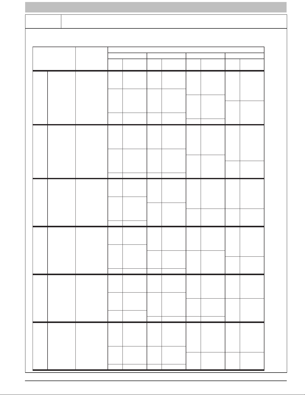
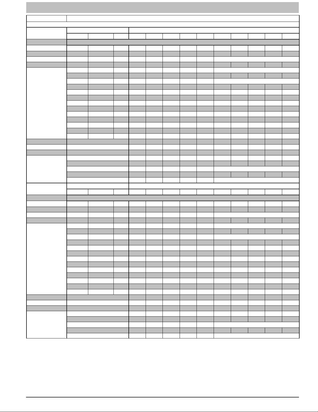
Table 4
Orifice Size and Manifold Pressure (in. w.c.) for Gas Input Rate
TO BE USED WITH MODULATING FURNACES EXCEPT THE (F/G)9MAE0602120
MODULATING FURNACE
(TABULATED DATA BASED ON 20,000 BT UH M AX-HEAT / 8,000 BTUH MIN-HEAT PER BURNER,
DERATED 2%/1000 FT (305M) ABOVE SEA LEVEL)
ALTITUDE
RANGE
ft (m)
092543 3.6 /0.55 43 3.7 /0.60 43 3.8 /0.60 42 3.2 /0.50
(0) 950 43 3.4 /0.55 43 3.5 /0.55 43 3.6 /0.60 43 3.7 /0.60
to 1000 44 3.5 /0.55 44 3.6 /0.60 44 3.8 /0.60 43 3.4 /0.55
U.S.A. and CanadaU.S.A. and CanadaU.S.A. Only
y
l
U.S.A. On
ly
U.S.A. On
ly
U.S.A. On
2000 1050 44 3.2 /0.50 44 3.3 /0.55 44 3.4 /0.55 44 3.5 /0.55
(610) 1075 45 3.7 /0.60 45 3.8 /0.60 44 3.3 /0.50 44 3.4 /0.55
U.S.A. 800 42 3.4 /0.55 42 3.5 /0.55 42 3.6 /0.55 42 3.7 /0.60
2001 (611) 825 43 3.8 /0.60 42 3.3 /0.50 42 3.4 /0.55 42 3.5 /0.55
to 850 43 3.6 /0.60 43 3.7 /0.60 42 3.2 /0.50 42 3.3 /0.55
3000 (914) 875 43 3.4 /0.55 43 3.5 /0.55 43 3.7 /0.60 43 3.8 /0.60
Canada 925 44 3.5 /0.55 44 3.6 /0.60 44 3.8 /0.60 43 3.4 /0.55
2001 (611) 950 44 3.3 /0.55 44 3.4 /0.55 44 3.6 /0.55 44 3.7 /0.60
to 975 44 3.2 /0.50 44 3.3 /0.50 44 3.4 /0.55 44 3.5 /0.55
4500 (1372) 1000 46 3.8 /0.60 45 3.8 /0.60 44 3.2 /0.50 44 3.3 /0.55
3001 800 43 3.8 /0.60 42 3.2 /0.50 42 3.3 /0.55 42 3.4 /0.55
(915) 825 43 3.6 /0.55 43 3.7 /0.60 43 3.8 /0.60 42 3.2 /0.50
to
4000 900 44 3.4 /0.55 44 3.5 /0.55 44 3.7 /0.60 44 3.8 /0.60
(1219) 925 44 3.2 /0.50 44 3.4 /0.55 44 3.5 /0.55 44 3.6 /0.55
4001 775 43 3.7 /0.60 43 3.8 /0.60 42 3.3 /0.50 42 3.4 /0.55
(1220) 800 43 3.5 /0.55 43 3.6 /0.60 43 3.7 /0.60 43 3.8 /0.60
to
5000 875 44 3.3 /0.55 44 3.5 /0.55 44 3.6 /0.55 44 3.7 /0.60
(1524) 900 44 3.2 /0.50 44 3.3 /0.50 44 3.4 /0.55 44 3.5 /0.55
5001 750 43 3.7 /0.60 43 3.8 /0.60 42 3.2 /0.50 42 3.3 /0.55
(1525) 775 43 3.4 /0.55 43 3.5 /0.55 43 3.7 /0.60 43 3.8 /0.60
to
6000 850 44 3.3 /0.50 44 3.4 /0.55 44 3.5 /0.55 44 3.6 /0.60
(1829) 875 45 3.7 /0.60 44 3.2 /0.50 44 3.3 /0.55 44 3.4 /0.55
6001 700 42 3.2 /0.50 42 3.3 /0.50 42 3.4 /0.55 42 3.5 /0.55
(1830) 725 43 3.6 /0.60 43 3.7 /0.60 43 3.8 /0.60 42 3.3 /0.50
to
7000 800 44 3.4 /0.55 44 3.5 /0.55 44 3.6 /0.60 44 3.7 /0.60
(2133) 825 44 3.2 /0.50 44 3.3 /0.55 44 3.4 /0.55 44 3.5 /0.55
HEATVALUE0.580.600.620.64
AT ALTITUDE Orifice Mnfld Press Orifice Mnfld Press Orifice Mnfld Press Orifice Mnfld Press
(Btu/cu ft) No. Max/Min No. Max/Min No. Max/Min No. Max/Min
900 43 3.8 /0.60 42 3.2 /0.50 42 3.3 /0.55 42 3.4 /0.55
975 44 3.7 /0.60 44 3.8 /0.60 43 3.4 /0.55 43 3.6 /0.55
1025 44 3.3 /0.55 44 3.5 /0.55 44 3.6 /0.55 44 3.7 /0.60
1100 46 3.7 /0.60 46 3.8 /0.60 45 3.8 /0.60 44 3.2 /0.50
900 44 3.7 /0.60 44 3.8 /0.60 43 3.5 /0.55 43 3.6 /0.55
775 42 3.3 /0.55 42 3.4 /0.55 42 3.5 /0.55 42 3.6 /0.60
850 44 3.8 /0.60 43 3.5 /0.55 43 3.6 /0.55 43 3.7 /0.60
875 44 3.6 /0.60 44 3.7 /0.60
950 45 3.7 /0.60 44 3.2 /0.50 44 3.3 /0.55 44 3.4 /0.55
750 42 3.3 /0.50 42 3.4 /0.55 42 3.5 /0.55 42 3.6 /0.55
825 44 3.8 /0.60 43 3.4 /0.55 43 3.5 /0.55 43 3.6 /0.60
850 44 3.5 /0.55 44 3.7 /0.60 44 3.8 /0.60 43 3.4 /0.55
925 46 3.8 /0.60 45 3.7 /0.60 44 3.2 /0.50 44 3.3 /0.55
725 42 3.2 /0.50 42 3.3 /0.55 42 3.4 /0.55 42 3.5 /0.55
800 44 3.7 /0.60 44 3.8 /0.60 43 3.4 /0.55 43 3.5 /0.55
825 44 3.5 /0.55 44 3.6 /0.55 44 3.7 /0.60 44 3.8 /0.60
900 46 3.7 /0.60 46 3.8 /0.60 45 3.8 /0.60 44 3.2 /0.50
675 42 3.4 /0.55 42 3.5 /0.55 42 3.6 /0.60 42 3.8 /0.60
750 43 3.4 /0.55 43 3.5 /0.55 43 3.6 /0.55 43 3.7 /0.60
775 44 3.6 /0.60 44 3.7 /0.60 43 3.4 /0.55 43 3.5 /0.55
850 46 3.8 /0.60 45 3.8 /0.60 44 3.2 /0.50 44 3.3 /0.55
43 3.4 /0.55 43 3.5 /0.55
SAGLARUTANFOYTIVARGCIFICEPSSAG.GVA
A11251A
440 04 4700 00 13
Specifications subject to change without notice.

SERVICE AND TECHNICAL SUPPORT MANUAL Gas Furnace: (F/G)9MAE
Table 4 (Cont.)
ALTITUDE
RANGE
U.S.A. Only
U.S.A. Only
U.S.A. Only
* Orifice numbers shown in BOLD are factory-ins talled.
Orifice Size and Manifold Pressure (in. w.c.) for Gas Input Rate
TO BE USED WITH MODULATING FURNACES EXCEPT THE (F/G)9MAE0602120
(TABULATED DATA BASED ON 20,000 BT UH M AX-HEAT / 8,000 BTUH MIN-HEAT PER BURNER,
HEATVALUE0.580.600.620.64
AT ALTITUDE Orifice Mnfld Press Orifice Mnfld Press Orifice Mnfld Press Orifice Mnfld Press
ft (m)
7001 675 43 3.8 /0.60 42 3.2 /0.50 42 3.3 /0.55 42 3.4 /0.55
(2134) 700 43 3.5 /0.55 43 3.7 /0.60 43 3.8 /0.60 42 3.2 /0.50
to
8000 775 44 3.3 /0.55 44 3.4 /0.55 44 3.5 /0.55 44 3.7 /0.60
(2438) 800 45 3.8 /0.60 44 3.2 /0.50 44 3.3 /0.55 44 3.4 /0.55
8001 650 43 3.8 /0.60 42 3.2 /0.50 42 3.3 /0.55 42 3.4 /0.55
(2439) 675 43 3.5 /0.55 43 3.6 /0.60 43 3.7 /0.60 42 3.2 /0.50
to
9000 750 44 3.3 /0.50 44 3.4 /0.55 44 3.5 /0.55 44 3.6 /0.55
(2743) 775 45 3.7 /0.60 44 3.2 /0.50 44 3.3 /0.50 44 3.4 /0.55
9001 600 42 3.3 /0.55 42 3.4 /0.55 42 3.6 /0.55 42 3.7 /0.60
(2744) 625 43 3.7 /0.60 42 3.2 /0.50 42 3.3 /0.55 42 3.4 /0.55
to
10000 700 44 3.4 /0.55 44 3.5 /0.55 44 3.7 /0.60 44 3.8 /0.60
(3048) 725 44 3.2 /0.50 44 3.3 /0.55 44 3.4 /0.55 44 3.5 /0.55
(Btu/cu ft) No. Max/Min No. Max/Min No. Max/Min No. Max/Min
650 42 3.4 /0.55 42 3.5 /0.55 42 3.6 /0.60 42 3.7 /0.60
725 44 3.8 /0.60 43 3.4 /0.55 43 3.5 /0.55 43 3.6 /0.60
750 44 3.5 /0.55 44 3.7 /0.60 44 3.8 /0.60 43 3.4 /0.55
825 46 3.7 /0.60 46 3.8 /0.60 45 3.8 /0.60 44 3.2 /0.50
625 42 3.4 /0.55 42 3.5 /0.55 42 3.6 /0.55 42 3.7 /0.60
700 44 3.7 /0.60 43 3.4 /0.55 43 3.5 /0.55 43 3.6 /0.55
725 44 3.5 /0.55 44 3.6 /0.60 44 3.7 /0.60 44 3.8 /0.60
650 43 3.5 /0.55 43 3.6 /0.55 43 3.7 /0.60 43 3.8 /0.60
675 44 3.7 /0.60 44 3.8 /0.60 43 3.4 /0.55 43 3.5 /0.55
MODULATING FURNACE
DERATED 2%/1000 FT (305M) ABOVE SEA LEVEL)
SAGLARUTANFOYTIVARGCIFICEPSSAG.GVA
A11251B
14 440 04 4700 00
Specifications subject to change without notice.
SERVICE AND TECHNICAL SUPPORT MANUAL Gas Furnace: (F/G)9MAE
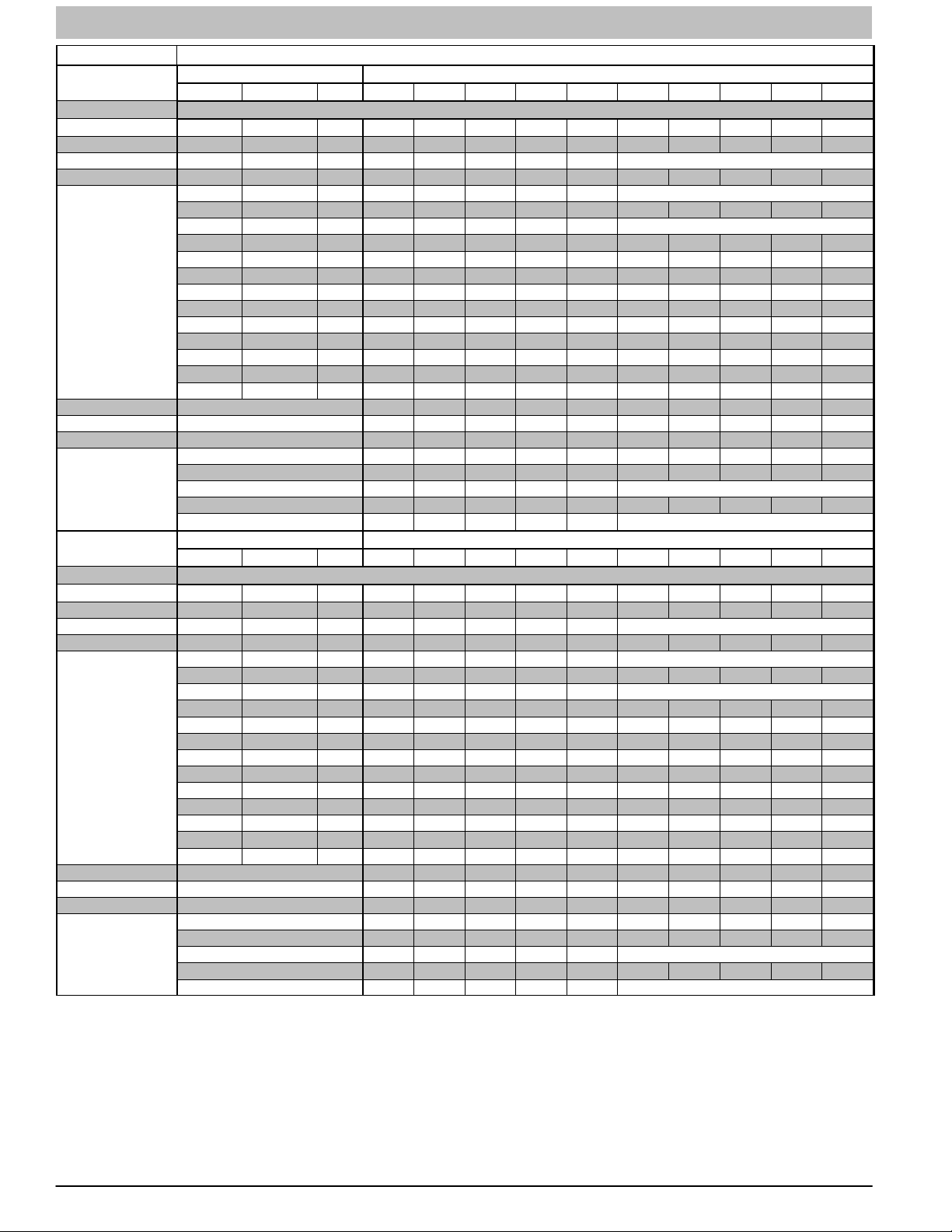
Table 5
Orifice Size and Manifold Pressure (in. w.c.) for Gas Input Rate
TO BE USED WITH MODULATING FURNACES (F/G)9MAE0602120 FURNACE ONLY
(TABULATED DATA BASED ON 20,200 BTUH MAX-HEAT / 8,000 BTUH MIN-HEAT PER BURNER,
DERATED 2%/1000 FT (305M) ABOVE SEA LEVEL)
ALTITUDE
RANGE
ft (m)
0 925 43 3.7 /0.55 43 3.8 /0.60 42 3.2 /0.50 42 3.3 /0.50
(0) 950 43 3.5 /0.55 43 3.6 /0.55 43 3.7 /0.60 43 3.8 /0.60
to 1000 44 3.6 /0.55 44 3.7 /0.60 44 3.8 /0.60 43 3.5 /0.55
U.S.A. and CanadaU.S.A. and CanadaU.S.A. Only
U.S.A. Only
U.S.A. Only
U.S.A. Only
2000 1050 44 3.3 /0.50 44 3.4 /0.55 44 3.5 /0.55 44 3.6 /0.55
(610) 1075 45 3.8 /0.60 44 3.2 /0.50 44 3.3 /0.50 44 3.4 /0.55
U.S.A. 800 42 3.4 /0.55 42 3.5 /0.55 42 3.7 /0.55 42 3.8 /0.60
2001 (611) 825 42 3.2 /0.50 42 3.3 /0.50 42 3.4 /0.55 42 3.6 /0.55
to 850 43 3.7 /0.60 43 3.8 /0.60 42 3.2 /0.50 42 3.3 /0.55
3000 (914) 875 43 3.5 /0.55 43 3.6 /0.55 43 3.7 /0.60 43 3.8 /0.60
Canada 925 44 3.6 /0.55 44 3.7 /0.60 44 3.8 /0.60 43 3.4 /0.55
2001 (611) 950 44 3.4 /0.55 44 3.5 /0.55 44 3.6 /0.55 44 3.7 /0.60
to 975 44 3.2 /0.50 44 3.3 /0.50 44 3.4 /0.55 44 3.6 /0.55
4500 (1372) 1000 45 3.7 /0.60 44 3.2 /0.50 44 3.3 /0.50 44 3.4 /0.55
3001 800 42 3.2 /0.50 42 3.3 /0.50 42 3.4 /0.55 42 3.5 /0.55
(915) 825 43 3.6 /0.55 43 3.7 /0.60 42 3.2 /0.50 42 3.3 /0.50
to
4000 900 44 3.5 /0.55 44 3.6 /0.55 44 3.7 /0.60 43 3.4 /0.55
(1219) 925 44 3.3 /0.50 44 3.4 /0.55 44 3.5 /0.55 44 3.6 /0.55
4001 775 43 3.8 /0.60 42 3.2 /0.50 42 3.3 /0.50 42 3.4 /0.55
(1220) 800 43 3.6 /0.55 43 3.7 /0.60 43 3.8 /0.60 42 3.2 /0.50
to
5000 875 44 3.4 /0.55 44 3.5 /0.55 44 3.6 /0.55 44 3.8 /0.60
(1524) 900 44 3.2 /0.50 44 3.3 /0.50 44 3.4 /0.55 44 3.6 /0.55
5001 750 43 3.7 /0.60 42 3.2 /0.50 42 3.3 /0.50 42 3.4 /0.55
(1525) 775 43 3.5 /0.55 43 3.6 /0.55 43 3.7 /0.60 42 3.2 /0.50
to
6000 850 44 3.3 /0.50 44 3.4 /0.55 44 3.6 /0.55 44 3.7 /0.60
(1829) 875 45 3.8 /0.60 44 3.3 /0.50 44 3.4 /0.55 44 3.5 /0.55
6001 700 42 3.2 /0.50 42 3.3 /0.50 42 3.5 /0.55 42 3.6 /0.55
(1830) 725 43 3.7 /0.60 43 3.8 /0.60 42 3.2 /0.50 42 3.3 /0.50
to
7000 800 44 3.5 /0.55 44 3.6 /0.55 44 3.7 /0.60 44 3.8 /0.60
(2133) 825 44 3.2 /0.50 44 3.4 /0.55 44 3.5 /0.55 44 3.6 /0.55
AVG. GAS SPECIFIC GRAVITY OF NATURAL GAS
HEAT VALUE 0.58 0.60 0.62 0.6 4
AT ALTITUDE Orifice Mnfld Press Orifice Mnfld Press Orifice Mnfld Press Orifice Mnfld Press
(Btu/cu ft) No. Max/Min No. Max/Min No. Max/Min No. Max/Min
900 42 3.2 /0.50 42 3.3 /0.50 42 3.4 /0.55 42 3.5 /0.55
975 44 3.8 /0.60 43 3.4 /0.55 43 3.5 /0.55 43 3.6 /0.55
1025 44 3.4 /0.55 44 3.5 /0.55 44 3.6 /0.55 44 3.8 /0.60
1100 46 3.8 /0.60 45 3.7 /0.60 44 3.2 /0.50 44 3.3 /0.50
900 44 3.8 /0.60 43 3.4 /0.55 43 3.5 /0.55 43 3.6 /0.55
775 42 3.4 /0.55 42 3.5 /0.55 42 3.6 /0.55 42 3.7 /0.60
850 43 3.4 /0.55 43 3.5 /0.55 43 3.6 /0.55 43 3.8 /0.60
875 44 3.7 /0.60 44 3.8 /0.60 43 3.4 /0.55 43 3.6 /0.55
950 45 3.8 /0.60 44 3.2 /0.50 44 3.4 /0.55 44 3.5 /0.55
750 42 3.3 /0.50 42 3.4 /0.55 42 3.6 /0.55 42 3.7 /0.55
825 44 3.8 /0.60 43 3.5 /0.55 43 3.6 /0.55 43 3.7 /0.60
850 44 3.6 /0.55 44 3.7 /0.60 43 3.4 /0.55 43 3.5 /0.55
925 45 3.7 /0.60 44 3.2 /0.50 44 3.3 /0.50 44 3.4 /0.55
725 42 3.3 /0.50 42 3.4 /0.55 42 3.5 /0.55 42 3.6 /0.55
800 44 3.8 /0.60 43 3.4 /0.55 43 3.5 /0.55 43 3.6 /0.55
825 44 3.5 /0.55 44 3.7 /0.55 44 3.8 /0.60 43 3.4 /0.55
900 46 3.8 /0.60 45 3.7 /0.60 44 3.2 /0.50 44 3.3 /0.50
675 42 3.5 /0.55 42 3.6 /0.55 42 3.7 /0.60 42 3.8 /0.60
750 43 3.4 /0.55 43 3.5 /0.55 43 3.7 /0.55 43 3.8 /0.60
775 44 3.7 /0.60 44 3.8 /0.60 43 3.4 /0.55 43 3.5 /0.55
850 45 3.7 /0.60 44 3.2 /0.50 44 3.3 /0.50 44 3.4 /0.55
L11F100A
440 04 4700 00 15
Specifications subject to change without notice.

SERVICE AND TECHNICAL SUPPORT MANUAL Gas Furnace: (F/G)9MAE
Table 5 (Cont.)
ALTITUDE
U.S.A. Only
U.S.A. Only
U.S.A. Only
* Orifice numbers shown in BOLD are factory-installed.
Orifice Size and Manifold Pressure (in. w.c.) for Gas Input Rate
TO BE USED WITH MODULATING FURNACES (F/G)9MAE0602120 FURNACE ONLY
(TABULATED DATA BASED ON 20,200 BTUH MAX-HEAT / 8,000 BTUH MIN-HEAT PER BURNER,
DERATED 2%/1000 FT (305M) ABOVE SEA LEVEL)
AVG. GAS SPECIFIC GRAVITY OF NATURAL GAS
RANGE
ft (m)
7001 675 42 3.2 /0.50 42 3.3 /0.50 42 3.4 /0.55 42 3.5 /0.55
(2134) 700 43 3.6 /0.55 43 3.7 /0.60 42 3.2 /0.50 42 3.3 /0.50
to
8000 775 44 3.4 /0.55 44 3.5 /0.55 44 3.6 /0.55 44 3.7 /0.60
(2438) 800 44 3.2 /0.50 44 3.3 /0.50 44 3.4 /0.55 44 3.5 /0.55
8001 650 42 3.2 /0.50 42 3.3 /0.50 42 3.4 /0.55 42 3.5 /0.55
(2439) 675 43 3.6 /0.55 43 3.7 /0.60 43 3.8 /0.60 42 3.2 /0.50
to
9000 750 44 3.3 /0.50 44 3.4 /0.55 44 3.5 /0.55 44 3.7 /0.55
(2743) 775 45 3.8 /0.60 44 3.2 /0.50 44 3.3 /0.50 44 3.4 /0.55
9001 600 42 3.4 /0.55 42 3.5 /0.55 42 3.6 /0.55 42 3.8 /0.60
(2744) 625 43 3.8 /0.60 42 3.2 /0.50 42 3.3 /0.55 42 3.5 /0.55
to
10000 700 44 3.5 /0.55 44 3.6 /0.55 44 3.7 /0.60 44 3.8 /0.60
(3048) 725 44 3.3 /0.50 44 3.4 /0.55 44 3.5 /0.55 44 3.6 /0.55
HEAT VALUE 0.58 0.60 0.62 0.64
AT ALTITUDE Orifice Mnfld Press Orifice Mnfld Press Orifice Mnfld Press Orifice Mnfld Press
(Btu/cu ft) No. Max/Min No. Max/Min No. Max/Min No. Max/Min
650 42 3.4 /0.55 42 3.6 /0.55 42 3.7 /0.60 42 3.8 /0.60
725 43 3.4 /0.55 43 3.5 /0.55 43 3.6 /0.55 43 3.7 /0.60
750 44 3.6 /0.55 44 3.7 /0.60 43 3.4 /0.55 43 3.5 /0.55
825 46 3.8 /0.60 45 3.7 /0.60 44 3.2 /0.50 44 3.3 /0.50
625 42 3.4 /0.55 42 3.5 /0.55 42 3.7 /0.55 42 3.8 /0.60
700 44 3.8 /0.60 43 3.4 /0.55 43 3.6 /0.55 43 3.7 /0.55
725 44 3.6 /0.55 44 3.7 /0.60 44 3.8 /0.60 43 3.4 /0.55
650 43 3.5 /0.55 43 3.6 /0.55 43 3.8 /0.60 42 3.2 /0.50
675 44 3.8 /0.60 43 3.4 /0.55 43 3.5 /0.55 43 3.6 /0.55
L11F100B
16 440 04 4700 00
Specifications subject to change without notice.
SERVICE AND TECHNICAL SUPPORT MANUAL Gas Furnace: (F/G)9MAE
Table 6 COOLING4 AND HEATING AIR DELIVERY - CFM (Bottom Return5 with Filter)
(SW1-5 and SW4-3 set to OFF, except as indicated. See notes 1 and 2)
Unit Size
060-14
Clg Default: OFF OFF OFF 1060 1070 1080 1080 1075 1065 1050 1035 1025 1010
CF Default: OFF OFF OFF 545 530 520 525 510 See note 4
Cooling (SW2)
Cont Fan (SW3)
Clg/CF Switch Settings External Static Pressure (ESP)
SWx-3 SWx-2 SWx-1 0.1 0.2 0.3 0.4 0.5 0.6 0.7 0.8 0.9 1.0
OFF OFF ON 545 530 520 525 510 See note 4
OFF ON OFF 710 710 710 695 690 See note 4
OFF ON ON 875 880 890 895 895 890 885 880 870 855
ON OFF OFF 1060 1070 1080 1080 1075 1065 1050 1035 1025 1010
ON OFF ON 1235 1240 1250 1255 1255 1250 1230 1190 1155 111 5
ON ON OFF 1235 1240 1250 1255 1255 1250 1230 1190 1155 111 5
ON ON ON 1235 1240 1250 1255 1255 1250 1230 1190 1155 1115
Clg SW2: Maximum Clg Airflow
Maximum Heat Airflow
Heating
(SW1)
Intermediate Heat Airflow
Minimum Heat Airflow
Unit Size
Clg/CF Switch Settings External Static Pressure (ESP)
SWx-3 SWx-2 SWx-1 0.1 0.2 0.3 0.4 0.5 0.6 0.7 0.8 0.9 1.0
2
3
1425 1425 1405 1370 1335 1300 1260 1225 1190 1155
3
1075 1085 1095 1095 1090 1080 1065 1050 1035 1020
3
535 515 505 515 495 See note 4
420 410 415 400 380 See note 4
060−20
Clg Default: OFF OFF OFF 1735 1735 1725 1715 1700 1685 1665 1650 1625 1605
CF Default: OFF OFF OFF 545 530 520 525 510 See note 4
OFF OFF ON 540 525 525 520 540 See note 4
OFF ON OFF 680 725 725 720 720 See note 4
OFF ON ON 925 915 910 895 900 890 875 865 860 855
Cooling (SW2)
ON OFF OFF 1070 1075 1080 1070 1080 1075 1055 1045 1030 1020
Cont Fan (SW3)
ON OFF ON 1215 1245 1235 1220 1220 1210 1200 1195 1185 1175
ON ON OFF 1380 1385 1395 1390 1395 1390 1380 1365 1355 1340
ON ON ON 1735 1735 1725 1715 1700 1685 1665 1650 1625 1605
Clg SW2: Maximum Clg Airflow
Maximum Heat Airflow
Heating
(SW1)
Intermediate Heat Airflow
Minimum Heat Airflow
440 04 4700 00 17
2
3
1955 1950 1940 1925 1905 1885 1855 1815 1745 1685
3
1080 1085 1095 1090 1095 1085 1070 1055 1045 1030
3
685 725 730 725 730 See note 4
560 555 555 550 565 See note 4
Specifications subject to change without notice.
SERVICE AND TECHNICAL SUPPORT MANUAL Gas Furnace: (F/G)9MAE
Table 6 (Cont.) COOLING4 AND HEATING AIR DELIVERY - CFM (Bottom Return5 with Filter)
Unit Size
080-14
Clg Default: OFF OFF OFF 1055 1065 1080 1075 1065 1050 1045 1035 1025 1005
CF Default: OFF OFF OFF 520 505 505 495 490 See note 4
Cooling (SW2)
Cont Fan (SW3)
Clg/CF Switch Settings External Static Pressure (ESP)
SWx-3 SWx-2 SWx-1 0.1 0.2 0.3 0.4 0.5 0.6 0.7 0.8 0.9 1.0
OFF OFF ON 520 505 505 495 490 See note 4
OFF ON OFF 665 685 680 660 665 See note 4
OFF ON ON 885 895 905 900 900 895 885 875 860 845
ON OFF OFF 1055 1065 1080 1075 1065 1050 1045 1035 1025 1005
ON OFF ON 1245 1245 1255 1255 1260 1255 1250 1235 1220 1185
ON ON OFF 1245 1245 1255 1255 1260 1255 1250 1235 1220 1185
ON ON ON 1245 1245 1255 1255 1260 1255 1250 1235 1220 1185
Clg SW2: Maximum Clg Airflow
Maximum Heat Airflow
Heating
(SW1)
Intermediate Heat Airflow
Minimum Heat Airflow
Unit Size
Clg/CF Switch Settings External Static Pressure (ESP)
SWx-3 SWx-2 SWx-1 0.1 0.2 0.3 0.4 0.5 0.6 0.7 0.8 0.9 1.0
2
3
1520 1485 1450 1415 1375 1335 1300 1265 1225 1190
3
1520 1485 1450 1415 1375 1335 1300 1265 1225 1190
3
755 745 755 755 765 See note 4
620 625 630 620 610 See note 4
080−20
Clg Default: OFF OFF OFF 1745 1755 1755 1760 1755 1750 1745 1725 1705 1685
CF Default: OFF OFF OFF 700 710 750 725 750 See note 4
OFF OFF ON 700 710 750 725 750 See note 4
OFF ON OFF 830 860 870 890 960 See note 4
OFF ON ON 1045 1045 1060 1070 1070 1070 1095 1090 1080 1070
Cooling (SW2)
ON OFF OFF 1215 1220 1245 1240 1235 1235 1225 1220 1235 1235
Cont Fan (SW3)
ON OFF ON 1370 1370 1390 1390 1400 1395 1400 1390 1390 1385
ON ON OFF 1745 1755 1755 1760 1755 1750 1745 1725 1705 1685
ON ON ON 1745 1755 1755 1760 1755 1750 1745 1725 1705 1685
Clg SW2: Maximum Clg Airflow
Maximum Heat Airflow
Heating
(SW1)
Intermediate Heat Airflow
Minimum Heat Airflow
18 440 04 4700 00
2
3
1920 1920 1945 1945 1945 1960 1950 1940 1915 1900
3
1340 1355 1370 1385 1380 1385 1400 1400 1385 1380
3
780 810 835 840 845 See note 4
595 595 600 595 605 See note 4
Specifications subject to change without notice.

SERVICE AND TECHNICAL SUPPORT MANUAL Gas Furnace: (F/G)9MAE
Table 6 (Cont.) COOLING4 AND HEATING AIR DELIVERY - CFM (Bottom Return5 with Filter)
Unit Size
100-22
Clg Default: OFF OFF OFF 1820 1825 1840 1845 1840 1835 1825 1805 1780 1770
CF Default: OFF OFF OFF 750 740 745 730 715 See note 4
Clg/CF Switch Settings External Static Pressure (ESP)
SWx-3 SWx-2 SWx-1 0.1 0.2 0.3 0.4 0.5 0.6 0.7 0.8 0.9 1.0
OFF OFF ON 750 740 745 730 715 See note 4
OFF ON OFF 900 900 915 910 905 See note 4
Cooling (SW2)
Cont Fan (SW3)
OFF ON ON 1070 1075 1095 1095 1090 1085 1095 1080 1065 1070
ON OFF OFF 1280 1285 1305 1305 1310 1305 1295 1300 1290 1285
ON OFF ON 1440 1445 1465 1465 1470 1485 1480 1485 1475 1460
ON ON OFF 1820 1825 1840 1845 1840 1835 1825 1805 1780 1770
ON ON ON 2135 2140 2140 2135 2140 2130 2115 2100 2070 2015
Clg SW2: Maximum Clg Airflow
Maximum Heat Airflow
Heating
(SW1)
Intermediate Heat Airflow
Minimum Heat Airflow
Unit Size
Clg/CF Switch Settings External Static Pressure (ESP)
SWx-3 SWx-2 SWx-1 0.1 0.2 0.3 0.4 0.5 0.6 0.7 0.8 0.9 1.0
2
3
2160 2165 2175 2170 2160 2150 2135 2120 2065 2020
3
1570 1575 1595 1595 1600 1605 1600 1600 1590 1575
3
950 955 965 975 970 See note 4
755 745 750 735 720 See note 4
120-22
Clg Default: OFF OFF OFF 1850 1855 1860 1855 1850 1830 1805 1775 1750 1730
CF Default: OFF OFF OFF 930 925 915 900 885 See note 4
OFF OFF ON 765 745 740 705 680 See note 4
OFF ON OFF 930 925 915 900 885 See note 4
OFF ON ON 1095 1100 111 0 1105 1085 See note 4
Cooling (SW2)
ON OFF OFF 1265 1255 1265 1280 1275 1285 1270 1260 1250 1230
Cont Fan (SW3)
ON OFF ON 1465 1455 1470 1465 1465 1470 1455 1450 1435 1415
ON ON OFF 1850 1855 1860 1855 1850 1830 1805 1775 1750 1730
ON ON ON 2200 2200 2200 2190 2185 2170 2145 2085 1990 1890
Clg SW2: Maximum Clg Airflow
Maximum Heat Airflow
Heating
(SW1)
Intermediate Heat Airflow
Minimum Heat Airflow
2
3
2200 2200 2200 2190 2185 2170 2145 2085 1990 1890
3
1815 1820 1825 1820 1815 1795 1775 1745 1720 1700
3
1095 1100 111 0 1105 1085 See note 4
905 900 890 875 855 See note 4
1. Nominal 350 CFM/ton cooling airflow is delivered with SW1−5 and SW4−3 set to OFF.
Set SW1−5 to ON for nominal 400 CFM/ton (+15% airflow).
Set SW4−3 to ON for nominal 325 CFM/ton (−7% airflow).
Set both SW1−5 and SW4−3 to ON for nominal 370 CFM/ton (+7% airflow).
The above adjustments in airflow are subject to motor horspower range/capacity.
2. Maximum cooling airflow is achieved when switches SW2−1, SW2−2, SW2−3 and SW1−5 are set to ON, and SW4−3 is set to OFF.
3. All heating CFM’s are when low/medium heat rise adjustment switch (SW1−3) and comfort/efficiency adjustment switch (SW1−4) are both
set to OFF.
4. Ductwork must be sized for high−heating CFM within the operational range of ESP. Operation within the blank areas of the chart is not
recommended because high−heat operation will be above 1.0 ESP.
5. All airflows on 21” casing size furnaces are 5% less on side return only installations.
6. Side returns for 24.5” casing sizes require two sides, or side and bottom, to allow sufficient airflow at the return of the furnace.
440 04 4700 00 19
Specifications subject to change without notice.

SERVICE AND TECHNICAL SUPPORT MANUAL Gas Furnace: (F/G)9MAE
Table 7
SECONDS G
FOR 1 REVOLUTION
10 360 720 1800 50 72 144 360
11 327 655 1636 51 71 141 355
12 300 600 1500 52 69 138 346
13 277 555 1385 53 68 136 340
14 257 514 1286 54 67 133 333
15 240 480 1200 55 65 131 327
16 225 450 1125 56 64 129 321
17 212 424 1059 57 63 126 316
18 200 400 1000 58 62 124 310
19 189 379 947 59 61 122 305
20 180 360 900 60 60 120 300
21 171 343 857 62 58 116 290
22 164 327 818 64 56 112 281
23 157 313 783 66 54 109 273
24 150 300 750 68 53 106 265
25 144 288 720 70 51 103 257
26 138 277 692 72 50 100 250
27 133 267 667 74 48 97 243
28 129 257 643 76 47 95 237
29 124 248 621 78 46 92 231
30 120 240 600 80 45 90 225
31 116 232 581 82 44 88 220
32 113 225 563 84 43 86 214
33 109 218 545 86 42 84 209
34 106 212 529 88 41 82 205
35 103 206 514 90 40 80 200
36 100 200 500 92 39 78 196
37 97 195 486 94 38 76 192
38 95 189 474 96 38 75 188
39 92 185 462 98 37 74 184
40 90 180 450 100 36 72 180
41 88 176 439 102 35 71 178
42 86 172 429 104 35 69 173
43 84 167 419 106 34 68 170
44 82 164 409 108 33 67 167
45 80 160 400 110 33 65 164
46 78 157 391 112 32 64 161
47 76 153 383 116 31 62 155
48 75 150 375 120 30 60 150
49 73 147 367
Gas Rate (CU ft./hr)
SIZE OF TEST DIAL
1 Cu Ft. 2 Cu Ft. 5 Cu Ft. 1 Cu Ft. 2 Cu Ft. 5 Cu Ft.
SECONDS
FOR 1 REVOLUTION
SIZE OF TEST DIAL
20 440 04 4700 00
Specifications subject to change without notice.

SERVICE AND TECHNICAL SUPPORT MANUAL Gas Furnace: (F/G)9MAE
SERVICE AND MAINTENANCE
PROCEDURES
! WARNING
FIRE, INJURY OR DEATH HAZARD
Failure to follow this warning could result in personal injury,
death and/or property damage.
The ability to properly perform service and maintenance on
this equipment requires certain knowledge, mechanical skills,
tools, and equipment. If you do not possess these, do not
attempt to perform any service and maintenance on this
equipment other than those procedures recommended in the
User’s Manual.
! CAUTION
ENVIRONMENTAL HAZARD
Failure to follow this caution may result in environmental
pollution.
Remove and recycle all components or materials (i.e. oil,
refrigerant, control board, etc.) before unit final disposal.
! WARNING
ELECTRICAL SHOCK, FIRE OR EXPLOSION HAZARD
Failure to follow this warning could result in personal injury or
death, or property damage.
Before installing, modifying, or servicing system, main
electrical disconnect switch must be in the OFF position and
install a lockout tag. There may be more than one
disconnect switch. Lock out and tag switch with a suitable
warning label. Verify proper operation after servicing.
! CAUTION
ELECTRICAL OPERATION HAZARD
Failure to follow this caution may result in improper furnace
operation or failure of furnace.
Label all wires prior to disconnection when servicing controls.
Wiring errors can cause improper and dangerous operation.
General
These instructions are written as if the furnace is installed in an
upflow application. An upflow furnace application is where the
blower is located below the combustion and controls section of
the furnace, and conditioned air is discharged upward. Since
this furnace can be installed in any of the four positions shown
in Figure 6, you must revise your orientation to component
location accordingly.
Figure 6 Multipoise Orientations
A93041
Electrical Controls and Wiring
! WARNING
ELECTRICAL SHOCK HAZARD
Failure to follow this warning could result in personal injury or
death.
There may be more than one electrical supply to the furnace.
Check accessories and cooling unit for additional electrical
supplies that must be shut off during furnace servicing. Lock
out and tag switch with a suitable warning label.
The electrical ground and polarity for 115−v wiring must be
properly maintained. Refer to Figure 7 for field wiring
information and to Figure 15 for furnace wiring information.
NOTE: If the polarity is not correct, the STATUS LED on the
control will flash code 10 and prevent the furnace from heating.
The control system also requires an earth ground for proper
operation of the control and flame−sensing electrode.
The 24−v circuit contains an automotive−type, 3−amp. fuse
located on the control. (See Figure 3) Any shorts of the 24−v
wiring during installation, service, or maintenance will cause
this fuse to blow. If fuse replacement is required, use ONLY a
3−amp. fuse. The control LED display will be off when fuse
needs replacing.
Troubleshooting
Refer to the service label. (See Figure 14—Service Label)
The Troubleshooting Chart− Flow Chart (See Figure 16) can
be a useful tool in isolating furnace operation problems.
Beginning with the word “Start,” answer each question and
follow the appropriate arrow to the next item.
The Chart − Flow Chart will help to identify the problem or failed
component. After replacing any component, verify correct
operation sequence.
Proper instrumentation is required to service electrical controls.
The control in this furnace is equipped with a Status Code LED
(Light−Emitting Diode) to aid in installation, servicing, and
troubleshooting. Status codes can be viewed at the sight glass
in blower access door. The amber furnace control LED is either
heartbeat, off or a code composed of 1 or 2 digits. The first digit
is the number of short flashes, the second digit is the number of
long flashes.
440 04 4700 00 21
Specifications subject to change without notice.
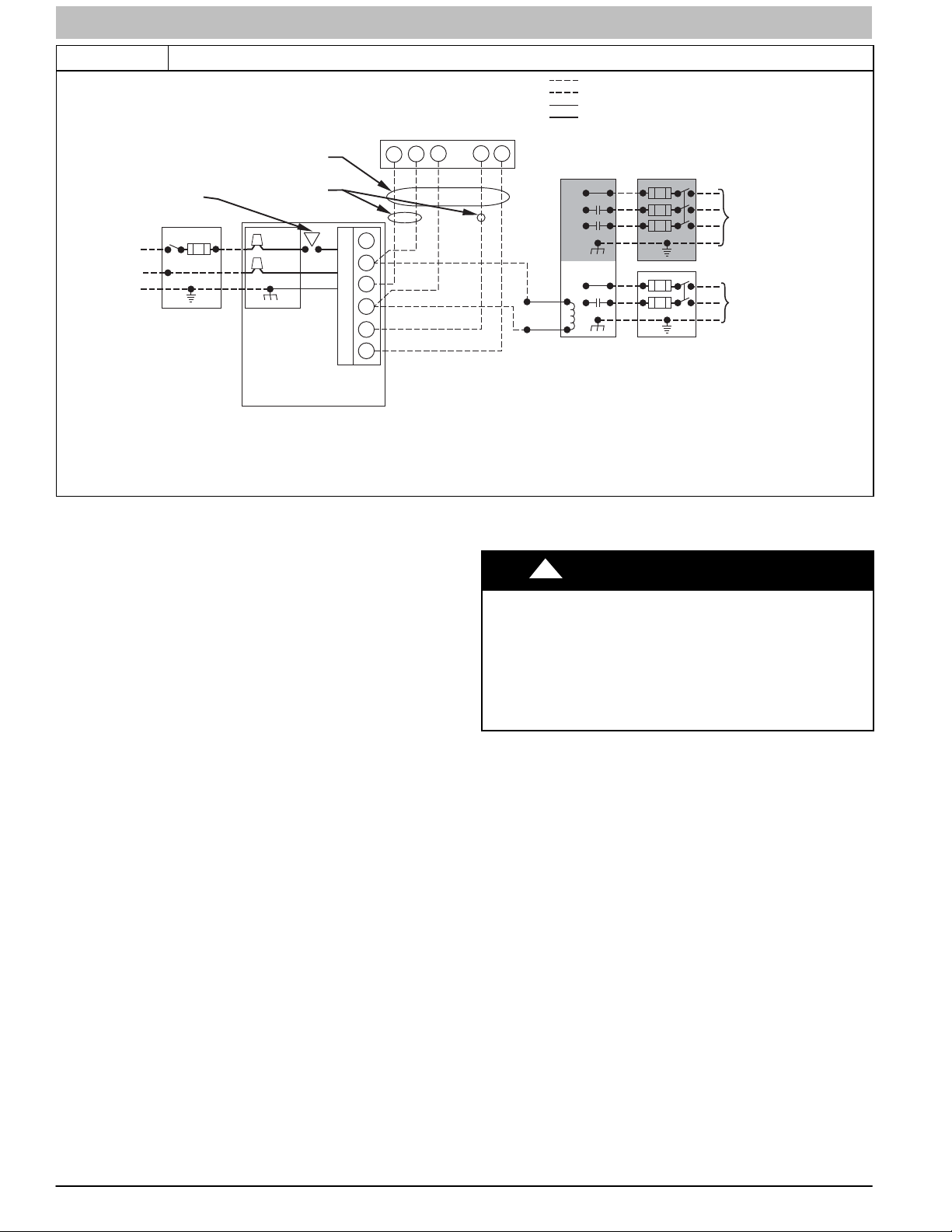
SERVICE AND TECHNICAL SUPPORT MANUAL Gas Furnace: (F/G)9MAE
Figure 7 Heating and Cooling Application Wiring Diagram with Single−Stage Thermostat
FIELD 24-VOLT WIRING
FIELD 115-, 208/230-, 460-VOLT WIRING
FACTORY 24-VOLT WIRING
FACTORY 115-VOLT WIRING
FIELD-SUPPLIED
FUSED DISCONNECT
GND
CONDENSING
UNIT
208/230- OR
460-VOLT
THREE
PHASE
208/230VOLT
SINGLE
PHASE
BLOWER
DOOR
SWITCH
BLK
WHT
GND
115-VOLT FIELD-
SUPPLIED
FUSED
DISCONNECT
BLK
WHT
JUNCTION
BOX
FIVE
WIRE
THREE-WIRE
HEATING-
ONLY
FURNACE
W2
C
COM
O
N
W/W1
T
Y/Y2
R
O
R
L
G
24-VOLT
TERMINAL
BLOCK
NOTE 2
WC Y RG
NOTE 1
NOTES: 1.
Connect Y/Y2-terminal as shown for proper operation.
Some thermostats require a "C" terminal connection as shown.
2.
If any of the original wire, as supplied, must be replaced, use
3.
same type or equivalent wire.
1-STAGE
THERMOSTAT
TERMINALS
For an explanation of status codes, refer to service label
located on blower access door or Figure 14, and the
Caution must be taken when manually closing this switch for
service purposes.
troubleshooting guide which can be obtained from your
distributor.
Retrieving Stored Fault Codes
The stored status codes will NOT be erased from the control
memory, when 115− or 24−v power is interrupted. The control
will store up to the last 7 Status Codes in order of occurrence.
1. To retrieve status codes, proceed with the following:
NOTE: NO thermostat signal may be present at control, and all
blower−OFF delays must be completed.
a. Leave 115−v power to furnace turned on.
b. Look into blower door sight glass for current LED
status.
c. Remove blower door.
NOTE: The Status Codes cannot be retrieved by
disconnecting the limit switch. To retrieve Status Codes, follow
the procedure below.
2. Turn Setup Switch, SW1−1 “ON.”
3. Manually close blower door switch.
4. Control will flash up to 7 Status Codes.
5. The last Status Code, or 8th Code, will be a heartbeat.
6. Turn SW1−1 “OFF.”
7. A heartbeat amber LED will appear and indicates proper
operation.
8. Release blower door switch, install blower door and or
refer to the SERVICE label for more information.
Component Self−Test
Component Test can ONLY be initiated by performing the
following:
1. Remove blower door.
2. Remove the wire from the “R” terminal of the control
board.
3. Turn Setup Switch, SW1−6 “ON.”
4. Manually close blower door switch.
ELECTRICAL SHOCK HAZARD
Failure to follow this warning could result in personal injury, or
death.
Blower door switch opens 115−v power to furnace control. No
component operation can occur unless switch is closed.
Exercise caution to avoid electrical shock from exposed
electrical components when manually closing this switch for
service purposes.
Component Test sequence will function as follows:
NOTE: The EAC terminals are energized when the blower is
operating.
After the component test is completed, 1 or more status codes
(heartbeat, 2+5, 3+5, 4+1, 4+2) will flash. See Service label on
control door or Service/status Code instructions for explanation
of status codes.
NOTE: To repeat component test, turn setup switch SW1−6 to
OFF and then back ON.
! WARNING
1. The furnace control CPU turns the inducer motor IDM
ON at medium speed and keeps it ON through Step 4.
2. The furnace control CPU will test communication with the
modulating gas valve GV.
3. After waiting 15 seconds the furnace control CPU turns
the hot surface igniter ON for 15 seconds, then OFF.
4. The furnace control CPU then turns the blower motor
BLWM ON at mid−range airflow for 15 seconds, then
OFF.
5. After shutting the blower motor BLWM OFF the furnace
control CPU shuts the inducer motor IDM OFF.
6. RELEASE BLOWER DOOR SWITCH, reattach wire to
“R” terminal on furnace control board, replace blower
door.
Blower door switch opens 115−v power to control. No
component operation can occur unless switch is closed.
22 440 04 4700 00
Specifications subject to change without notice.
A11401
SERVICE AND TECHNICAL SUPPORT MANUAL Gas Furnace: (F/G)9MAE
Care and Maintenance
! WARNING
FIRE OR EXPLOSION HAZARD
Failure to follow this warning could result in personal injury,
death and/or property damage.
Never store anything on, near, or in contact with the furnace,
such as:
1. Spray or aerosol cans, rags, brooms, dust mops,
vacuum cleaners, or other cleaning tools.
2. Soap powders, bleaches, waxes or other cleaning
compounds, plastic or plastic containers, gasoline,
kerosene, cigarette lighter fluid, dry cleaning fluids, or
other volatile fluids.
3. Paint thinners and other painting compounds, paper
bags, or other paper products. Exposure to these
materials could lead to corrosion of the heat
exchangers.
For continuing high performance and to minimize possible
furnace failure, periodic maintenance must be performed on
this furnace. Consult your local dealer about proper frequency
of maintenance and the availability of a maintenance contract.
! WARNING
ELECTRICAL SHOCK AND FIRE HAZARD
Failure to follow this warning could result in personal injury,
death, and/or property damage.
Turn off the gas and electrical supplies to the furnace and
install lockout tag before performing any maintenance or
service. Follow the operating instructions on the label
attached to the furnace.
! WARNING
CARBON MONOXIDE POISONING AND FIRE HAZARD
Failure to follow this warning could result in personal injury,
death and/or property damage.
Never operate furnace without a filter or with filter access
door removed.
! CAUTION
CUT HAZARD
Failure to follow this caution may result in personal injury.
Sheet metal parts may have sharp edges or burrs. Use care
and wear appropriate protective clothing, safety glasses and
gloves when handling parts, and servicing furnaces.
The minimum maintenance on this furnace is as follows:
1. Check and clean air filter each month or more frequently
if required. Replace if torn.
2. Check blower motor and wheel for cleanliness each
heating and cooling season. Clean as necessary.
3. Check electrical connections for tightness and controls
for proper operation each heating season. Service as
necessary.
4. Inspect burner compartment before each heating season
for rust, corrosion, soot or excessive dust. If necessary,
have furnace and burner serviced by a qualified service
agency.
5. Inspect the vent pipe/vent system before each heating
season for water leakage, sagging pipes or broken
fittings. Have vent pipes/vent system serviced by a
qualified service agency.
6. Inspect any accessories attached to the furnace such as
a humidifier or electronic air cleaner. Perform any service
or maintenance to the accessories as recommended in
the accessory instructions.
Cleaning and/or Replacing Air Filter
The air filter arrangement will vary depending on the
application.
NOTE: If the filter has an airflow direction arrow, the arrow
must point towards the blower.
To clean or replace filters, proceed as follows:
! WARNING
ELECTRICAL SHOCK, FIRE OR EXPLOSION HAZARD
Failure to follow this warning could result in personal injury or
death, or property damage.
Before installing, modifying, or servicing system, main
electrical disconnect switch must be in the OFF position and
install a lockout tag. There may be more than one
disconnect switch. Lock out and tag switch with a suitable
warning label. Verify proper operation after servicing.
1. Turn off electrical supply to furnace.
2. Remove filter cabinet door.
3. Slide filter out of cabinet.
4. If equipped with permanent, washable filter, clean filter by
spraying cold tap water through filter in opposite direction
of airflow. Rinse filter and let dry. Oiling or coating of the
filter is not recommended.
5. If equipped with factory specified disposable media filter,
replace only with a factory specified media filter of the
same size.
6. Slide filter into cabinet.
7. Replace filter cabinet door.
8. Turn on electrical supply to furnace.
Blower Motor and Wheel Maintenance
To ensure long life, economy, and high efficiency, clean
accumulated dirt and grease from blower wheel and motor
annually.
The inducer and blower motors are pre−lubricated and require
no additional lubrication. These motors can be identified by the
absence of oil ports on each end of the motor.
The following items should be performed by a qualified service
technician. Clean blower motor and wheel as follows:
1. Turn off electrical supply to furnace.
2. Remove blower door.
3. All factory wires can be left connected, but field
thermostat and accessory wiring may need to be
disconnected depending on their length and routing.
4. If the vent and combustion air pipe passes through the
blower compartment, it will be necessary to remove the
pipes from the blower compartment.
Disconnect the vent and combustion air pipe by:
a. Loosen the clamps on the vent couplings and
combustion air pipe external to the furnace.
b. Separate the pipes from the couplings and move
them aside.
c. Loosen the clamps on the vent couplings and
combustion air pipe located on the blower shelf.
440 04 4700 00 23
Specifications subject to change without notice.
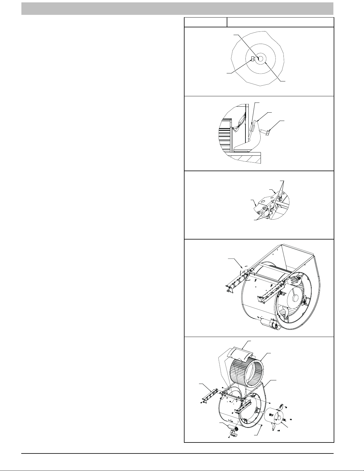
SERVICE AND TECHNICAL SUPPORT MANUAL Gas Furnace: (F/G)9MAE
d. Separate the pipes from the blower compartment and
set aside.
e. Remove the couplings from the pipe adapters and set
aside.
f. After servicing the blower, reverse steps a through e.
g. Tighten all clamps 15 lb−in.
See Figure 8 for steps 5 through 14.
5. Remove screws securing blower assembly to blower
shelf and slide blower assembly out of furnace. Detach
ground wire and disconnect blower motor harness plugs
from blower motor.
NOTE: Blower wheel is fragile. Use care.
6. Clean blower wheel and motor by using a vacuum with
soft brush attachment. Be careful not to disturb balance
weights (clips) on blower wheel vanes. Do not bend
wheel or blades as balance will be affected.
7. If greasy residue is present on blower wheel, remove
wheel from the blower housing and wash it with an
appropriate degreaser. To remove wheel:
a. Mark blower wheel location on shaft before disassembly
to ensure proper reassembly.
b. Loosen setscrew holding blower wheel on motor shaft.
NOTE: Mark blower mounting arms and blower housing so
each arm is positioned at the same hole location during
reassembly.
c. Mark blower wheel orientation and cutoff plate location
to ensure proper reassembly.
d. Remove screws securing cutoff plate and remove cutoff
plate from housing.
e. Remove bolts holding motor mounts to blower housing
and slide motor and mounts out of housing.
f. Remove blower wheel from housing.
g. Clean wheel per instructions on degreaser cleaner. Do
not get degreaser in motor.
8. Reassemble motor and blower wheel by reversing items
7b through 7f. Ensure wheel is positioned for proper
rotation.
9. Torque motor mounting bolts to 40 +/− 10 lb−in. when
reassembling.
10. Torque blower wheel set screw to 160 +/− 20 lb−in. when
reassembling.
11. Verify that blower wheel is centered in blower housing
and set screw contacts the flat portion of the motor shaft.
Loosen set screw on blower wheel and reposition if
necessary.
12. Spin the blower wheel by hand to verify that the wheel
does not rub on the housing.
13. Reinstall blower assembly in furnace.
14. Reinstall two (2) screws securing blower assembly to
blower deck.
15. Reconnect blower leads to furnace control. Refer to
furnace wiring diagram, and connect thermostat leads if
previously disconnected.
NOTE: Be sure to attach ground wire and reconnect blower
harness plugs to blower motor.
Figure 8 Blower Assembly
MOTOR SHAFT FLAT
SET SCREW
GROMMET
MOTOR ARM
SCREW LOCATION
BLO HSG ASSY
BRACKET
BRACKET
ENGAGEMENT
DETAIL A
SEE DETAIL A
CUTOFF, BLOWER
WHEEL, BLOWER
BRACKET
MOTOR WHEEL HUB
A11584A
SCREW
A11584B
A11584C
A11584D
BLOWER HSG ASSY
POWER CHOKE
OR CAPACITOR
WHEN REQUIRED
24 440 04 4700 00
Specifications subject to change without notice.
SCREW
(GND)
MOTOR, BLOWER
A11584E

SERVICE AND TECHNICAL SUPPORT MANUAL Gas Furnace: (F/G)9MAE
2. Turn off gas at external shut-off or gas meter.
! WARNING
ELECTRICAL SHOCK HAZARD
Failure to follow this warning could result in personal injury, or
death.
Blower access door switch opens 115−v power to furnace
control. No component operation can occur unless switch is
closed. Exercise caution to avoid electrical shock from
exposed electrical components when manually closing this
switch for service purposes.
16. Downflow or horizontal furnaces with vent pipe through
furnace only:
a. Install and connect short piece of vent pipe inside
furnace to existing vent.
b. Connect vent connector to vent elbow.
17. Turn on electrical supply. If outdoor temperature is below
70_F (21_C), turn off circuit breaker to outdoor unit
before running furnace in the cooling cycle. Manually
close blower access panel door switch. Use a piece of
tape to hold switch closed. Check for proper rotation and
speed changes between heating and cooling by
jumpering R to G and R to Y/Y2 on furnace control
thermostat terminals. Turn outdoor circuit breaker on
after completing cooling cycle. (See Figure 3)
NOTE: If R−W/W1 thermostat terminals are jumpered at the
time blower access door switch is closed, blower will run for 90
seconds before beginning a heating cycle.
a. Perform component self−test as shown at the bottom of
the SERVICE label, located on the front of blower
access door.
b. Verify blower is rotating in the correct direction
18. If furnace is operating properly, RELEASE BLOWER
ACCESS DOOR SWITCH. Remove any jumpers or
reconnect any disconnected thermostat leads. Replace
blower access door.
19. Downflow or horizontal furnaces with vent pipe through
furnace only:
a. Install and connect short piece of vent pipe inside
furnace to existing vent.
b. Connect vent connector to vent elbow.
20. Reinstall outer door.
21. Turn on gas supply and cycle furnace through one
complete heating cycle. Verify the furnace temperature
rise as shown in Adjustments Section. Adjust
temperature rise as shown in Adjustments Section.
Cleaning Burners and Flame Sensor
The following items must be performed by a qualified service
technician. If the burners develop an accumulation of light dirt
or dust, they may be cleaned by using the following procedure:
NOTE: Use a back-up wrench on the gas valve to prevent the
valve from rotating on the manifold or damaging the mounting
to the burner assembly.
Refer to Figure 9.
1. Disconnect power at external disconnect, fuse or circuit
breaker.
3. Remove outer doors and set aside.
4. Turn electric switch on gas valve to OFF.
5. Disconnect the gas pipe from gas valve and remove pipe
from the furnace casing.
6. Disconnect the connector harness from gas valve.
7. Disconnect Hot Surface Igniter (HSI) wires from HSI.
8. Disconnect Flame Sensor wire from Flame Sensor.
9. Support the manifold and remove the four (4) screws that
secure the manifold assembly to the burner assembly
and set aside. Note the location of the green/yellow wire
and ground terminal.
10. Inspect the orifices in the manifold assembly for
blockages or obstructions. Remove orifice and clean or
replace orifice.
11. Remove the four (4) screws that attach the top plate of
the casing to the furnace.
12. Raise top plate up slightly and prop it up with a small
piece of wood or folded cardboard.
13. Support the burner assembly and remove the screws
that attach the burner assembly to the heat exchanger
cell panel.
14. Remove wires from both rollout switches.
15. Slide one-piece burner assembly out of slots on sides of
burner assembly.
16. Remove the flame sensor from the burner assembly.
17. (Optional) Remove the Hot Surface Igniter (HSI) and
bracket from the burner assembly.
18. Check igniter resistance. Nominal resistance is 40 to 70
ohms at room temperature and is stable over the life of
the igniter.
19. Clean burner assembly with a brush and a vacuum.
20. Clean the flame sensor with fine steel wool (0000 grade).
Do not use sand paper or emery cloth.
To reinstall burner assembly:
1. Install the Hot Surface Igniter (HSI) and bracket in burner
assembly.
2. Install flame sensor on burner assembly.
3. Align the edges of the one-piece burner assembly with
the slots in the burner assembly and slide the burners
forward until they are fully seated in the burner
assembly.
4. Align the orifices in the manifold assembly with the
support rings on the end of the burner.
5. Insert the orifices in the support rings of the burners.
NOTE: If manifold does not fit flush against the burner
assembly, do not force the manifold on the burner assembly.
The burners are not fully seated forward in the burner
assembly. Remove the manifold and check burner positioning
in the burner assembly before re-installing the manifold.
6. Attach the green/yellow wire and ground terminal to one
of the manifold mounting screws.
7. Install the remaining manifold mounting screws.
8. Check the igniter alignment. See Figure 9, Figure 10
and Figure 11.
440 04 4700 00 25
Specifications subject to change without notice.

SERVICE AND TECHNICAL SUPPORT MANUAL Gas Furnace: (F/G)9MAE
Figure 9 Burner Assembly
BURNER SUPT. ASSY
BURNER ASSY
FLAME ROLL−OUT SWITCH
FLAME SENSOR
(
BELOW BURNER)
L11F064
Representative drawing only, some models may vary in appearance.
Figure 10 Igniter Position − Top View
1-1/4-in.
(31.8)
2-1/2-in.
(64.4)
A11405
9. Attach the wires to the roll-out switches.
10. Align the burner assembly with the openings in the
primary cell inlet panel and attach the burner assembly to
the cell panel.
11. Connect the wire for the flame sensor
12. Connect the wire for the Hot Surface Igniter.
NOTE: Use propane-resistant pipe dope to prevent leaks. Do
not use Teflon tape.
13. Install the gas pipe to the gas valve.
! WARNING
FIRE OR EXPLOSION HAZARD
Failure to follow this warning could result in personal injury,
death, and/or property damage.
Never purge a gas line into a combustion chamber. Never
test for gas leaks with an open flame. Use a commercially
available soap solution made specifically for the detection of
leaks to check all connections. A fire or explosion may result
causing property damage, personal injury or loss of life.
14. Check for gas leaks with a soap and water solution.
15. Turn gas on at electric switch on gas valve and at
external shut-off or meter
Figure 11 Igniter Position − Side View
2ïin.
50 mm
3/8ïin.
9.6 mm
3/16ïin.
4.6 mm
+ 1/32
1/10ïin.
ï 1/16ïin.
+0.8
2.5 mm
ï1.5 mm
L12F041
16. Turn power on at external disconnect, fuse or circuit
breaker.
17. Run the furnace through two complete heating cycles to
check for proper operation
18. Install outer door when complete.
Servicing Hot Surface Igniter
The igniter does NOT require annual inspection. Check igniter
resistance before removal. Refer to Figure 9, Figure 10 and
Figure 11.
1. Turn off gas and electrical supplies to furnace.
2. Remove control door.
3. Disconnect igniter wire connection.
4. Check igniter resistance. Igniter resistance is affected by
temperature. Only check resistance when the igniter is at
room temperature.
a. Using an ohm meter, check resistance across both
igniter leads in connector.
b. Cold reading should be between 40 ohms and 70 ohms.
Resistance reading will increase as igniter temperature
increases.
5. Remove igniter assembly.
a. Using a 1/4−in. driver, remove the two screws securing
the igniter mounting bracket to the burner assembly.
(See Figure 9)
b. Carefully withdraw the igniter and bracket assembly
through the front of the burner assembly without striking
the igniter on surrounding parts.
c. Inspect igniter for signs of damage or failure.
d. If replacement is required, remove the screw that
secures the igniter on igniter bracket and remove the
igniter.
6. To replace igniter and bracket assembly, reverse items
5a through 5e.
7. Reconnect igniter harness to the igniter, dressing the
igniter wires to ensure there is no tension on the igniter
itself. (See Figure 9)
26 440 04 4700 00
Specifications subject to change without notice.
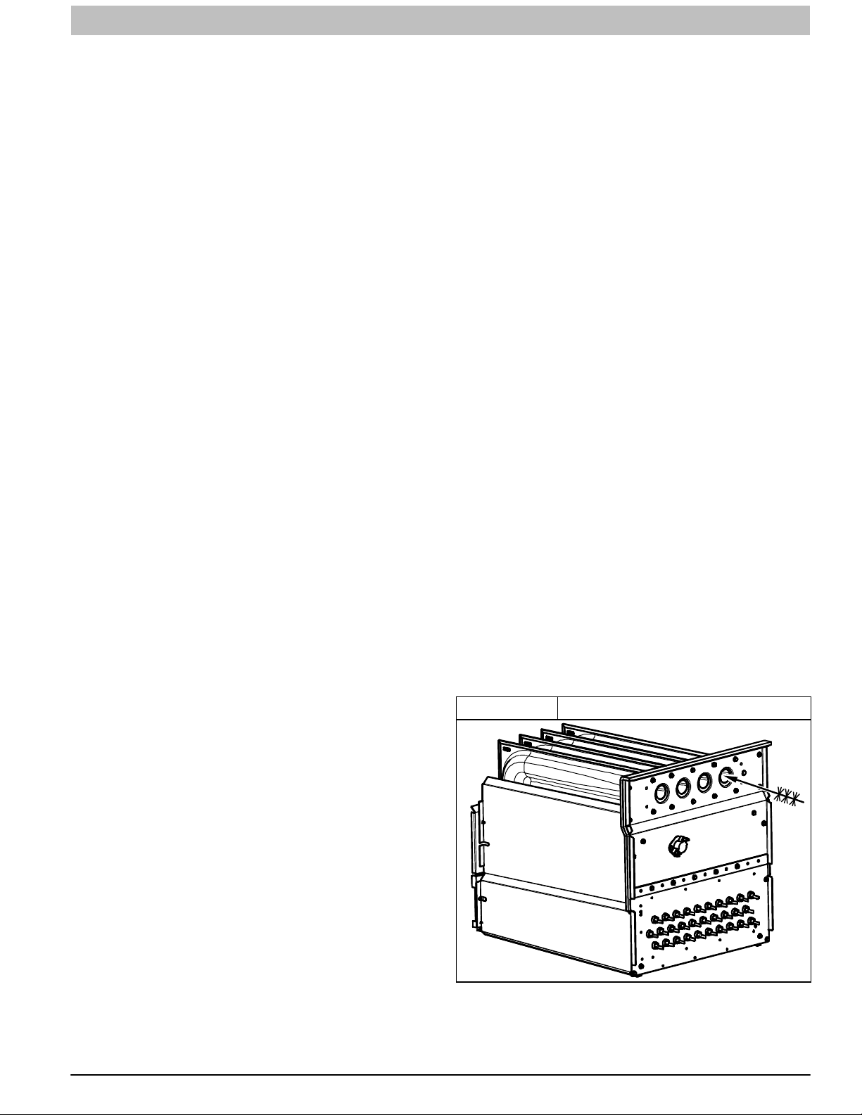
SERVICE AND TECHNICAL SUPPORT MANUAL Gas Furnace: (F/G)9MAE
8. Turn on gas and electrical supplies to furnace.
9. Verify igniter operation by initiating control board self−test
feature or by cycling thermostat.
10. Replace control door.
Flushing Collector Box and Drainage System
1. Turn off gas and electrical supplies to furnace.
2. Remove control door.
3. Disconnect pressure switch tube from pressure switch
port.
NOTE: Ensure the pressure switch tube disconnected from the
pressure switch is higher than the collector box opening or
water will flow out of tube.
4. Remove one of the collector box plugs from a port on the
upper corner of the collector box. (See Figure 1)
5. Attach a funnel with a flexible tube to port on the collector
box.
6. Flush inside of collector box with water until discharge
from condensate trap is clean and runs freely.
7. Repeat steps 4 through 6 with middle plug on upper
corner of collector box.
8. Remove the pressure switch tube from the collector box.
NOTE: Do Not blow into tube with tube connected to the
pressure switch.
9. Clean pressure switch port on collect box with a small
wire. Shake any water out of pressure switch tube.
10. Reconnect tube to pressure switch and pressure switch
port.
11. Remove the relief tube from the port on the collector box
and the trap.
12. Clean the relief port on collect box and the trap with a
small wire. Shake any water out of the tube.
13. Reconnect relief tube to trap and collector box ports.
Cleaning Condensate Drain and Trap
NOTE: If the condensate trap is removed, a new gasket
between the trap and collector box is required. Verify a
condensate trap gasket is included in the service kit or obtain
one from your local distributor.
1. Disconnect power at external disconnect, fuse or circuit
breaker.
2. Turn off gas at external shut-off or gas meter.
3. Remove outer doors and set aside.
4. Turn electric switch on gas valve to OFF.
5. Disconnect external drain from condensate drain elbow
or drain extension pipe inside the furnace and set aside.
6. Disconnect the condensate trap relief hose from collector
box port and condensate trap.
NOTE: If condensate has a heat pad attached to the trap,
trace the wires for the pad back to the connection point and
disconnect the wires for the heat pad.
7. Remove the screw that secures the condensate trap to
the collector box, remove the trap and set aside.
8. Remove the trap gasket from the collector box if it did not
come off when the trap was removed.
9. Discard the old trap gasket.
10. Rinse condensate trap in warm water until trap is clean.
11. Flush condensate drain lines with warm water.
Remember to check and clean the relief port on the
collector box.
12. Shake trap dry.
13. Clean port on collector box with a small wire.
To re-install Condensate Drain and Trap:
1. Remove adhesive backing from condensate trap gasket
2. Install gasket on collector box
3. Align the condensate trap with the drain opening on the
collector box and secure the trap with the screw
4. Attach the relief hose to the relief port on the condensate
trap and collector box.
5. Secure tubing to prevent any sags or traps in the tubing.
6. Connect condensate drain elbow or drain extension
elbow to the condensate trap
7. Connect the leads of the condensate heat pad (if used)
8. Connect external drain piping to the condensate drain
elbow or drain extension pipe.
9. Turn gas on at electric switch on gas valve and at
external shut-off or meter
10. Turn power on at external disconnect, fuse or circuit
breaker.
11. Run the furnace through two complete heating cycles to
check for proper operation
12. Install outer door when complete.
Checking Heat Pad Operation (If Applicable)
In applications where the ambient temperature around the
furnace is 32_F (0_C) or lower, freeze protection measures are
required. If this application is where heat tape has been
applied, check to ensure it will operate when low temperatures
are present.
NOTE: The Heat Pad, when used, should be wrapped around
the condensate drain trap. There is no need to use heat tape
within the furnace casing. Most heat tapes are temperature
activated, and it is not practical to verify the actual heating of
the tape. Check the following:
1. Check for signs of physical damage to heat tape such as
nicks, cuts, abrasions, gnawing by animals, etc.
2. Check for discolored heat tape insulation. If any damage
or discolored insulation is evident, replace heat tape.
3. Check that heat tape power supply circuit is on.
Cleaning Heat Exchangers
The following items must be performed by a qualified service
technician.
Primary Heat Exchangers
If the heat exchangers get an accumulation of light dirt or dust
on the inside, they may be cleaned by the following procedure:
Figure 12 Cleaning Heat Exchanger Cell
NOTE: If the heat exchangers get a heavy accumulation of
soot and carbon, both the primary and secondary heat
exchangers should be replaced rather than trying to clean them
thoroughly due to their intricate design. A build−up of soot and
carbon indicates that a problem exists which needs to be
440 04 4700 00 27
Specifications subject to change without notice.

SERVICE AND TECHNICAL SUPPORT MANUAL Gas Furnace: (F/G)9MAE
corrected, such as improper adjustment of manifold pressure,
insufficient or poor quality combustion air, improper vent
termination, incorrect size or damaged manifold orifice(s),
improper gas, or a restricted heat exchanger (primary or
secondary). Action must be taken to correct the problem.
1. Turn off gas and electrical supplies to furnace.
2. Remove control door.
3. Disconnect wires or connectors to flame rollout switch,
gas valve, igniter, and flame sensor.
4. Using backup wrench, disconnect gas supply pipe from
furnace gas control valve.
5. Remove two screws attaching top filler panel and rotate
upwards to gain access to screws attaching burner
assembly to cell panel.
6. Remove screws attaching burner assembly to cell panel.
(See Figure 9)
NOTE: Burner assembly, cover, manifold, gas valve, and
burner assembly should be removed as one assembly.
7. Clean heat exchanger openings with a vacuum and a
soft brush. (See Figure 12)
NOTE: After cleaning, inspect the heat exchangers to ensure
they are free of all foreign objects that may restrict flow of
combustion products.
8. Reverse items 6 through 1 for reassembly.
9. Refer to furnace wiring diagram and reconnect wires to
flame rollout switch, gas valve, igniter, and flame sensor.
10. Turn on gas and electrical supplies to furnace.
11. Check furnace operation through 2 complete heat
operating cycles. Look through sight glass in burner
enclosure to check burners. Burner flames should be
clear blue, almost transparent. (See Figure 13)
Figure 13 Burner Flame
Burner Flame
Burner
Manifold
A11461
! WARNING
FIRE OR EXPLOSION HAZARD
Failure to follow this warning could result in personal injury,
death, and/or property damage.
Never purge a gas line into a combustion chamber. Never
test for gas leaks with an open flame. Use a commercially
available soap solution made specifically for the detection of
leaks to check all connections. A fire or explosion may result
causing property damage, personal injury or loss of life.
12. Check for gas leaks.
13. Replace control door.
Secondary Heat Exchangers
The condensing side (inside) of the secondary heat exchanger
CANNOT be serviced or inspected without complete removal of
the heat exchanger assembly. Detailed information on heat
exchanger removal can be obtained from your Distributor.
Winterization
!
UNIT AND PROPERTY DAMAGE HAZARD
Failure to follow this caution may result in unit
component or property damage.
If the furnace is installed in an unconditioned space
where the ambient temperatures may be 32_ F (0_ C) or
lower, freeze protection measures must be taken to
prevent property or product damage.
Since the furnace uses a condensing heat exchanger, some
water will accumulate in the unit as a result of the heat transfer
process. Therefore, once it has been operated, it cannot be
turned off and left off for an extended period of time when
temperatures will reach 32_F (0_C) or lower unless winterized.
Follow these procedures to winterize your furnace:
!
UNIT COMPONENT DAMAGE HAZARD
Failure to follow this caution may result in damage to the
furnace and other property damage.
Do not use ethylene glycol (automotive antifreeze
coolant or equivalent). Failure of plastic components
may occur.
1. Obtain propylene glycol (RV/swimming pool antifreeze or
equivalent).
2. Turn off gas and electrical supplies to your furnace.
3. Remove furnace control door.
4. Remove the top unused rubber plug from the port on the
collector box opposite the condensate trap. (See
Figure 1)
5. Connect a field supplied 3/8−in. (9.5−mm) ID tube to the
open port on the collector box
6. Insert a field supplied funnel into the tube.
7. Pour one quart of anti−freeze solution into the
funnel/tube. Antifreeze should run through the collector
box, overfill condensate trap and flow to an open drain.
8. Replace the rubber plug in the port on the collector box.
9. Remove the middle unused rubber plug from the port on
the collector box opposite the condensate trap. See
Figure 1.
10. Repeat Steps 5 through 8.
11. If a condensate pump is used, check with pump
manufacturer to verify pump is safe for use with
antifreeze used. Allow pump to start and pump
anti−freeze to open drain.
12. Replace main door.
13. When furnace is re−started, flush condensate pump with
clear water to check for proper operation before
re−starting furnace.
14. Propylene glycol need not be removed before re−starting
furnace.
CAUTION
CAUTION
28 440 04 4700 00
Specifications subject to change without notice.

SERVICE AND TECHNICAL SUPPORT MANUAL Gas Furnace: (F/G)9MAE
Figure 14 Service Label
338316−2 Rev I
440 04 4700 00 29
Specifications subject to change without notice.

SERVICE AND TECHNICAL SUPPORT MANUAL Gas Furnace: (F/G)9MAE
Figure 15 Wiring Diagram
338316−2 Rev I
30 440 04 4700 00
Specifications subject to change without notice.
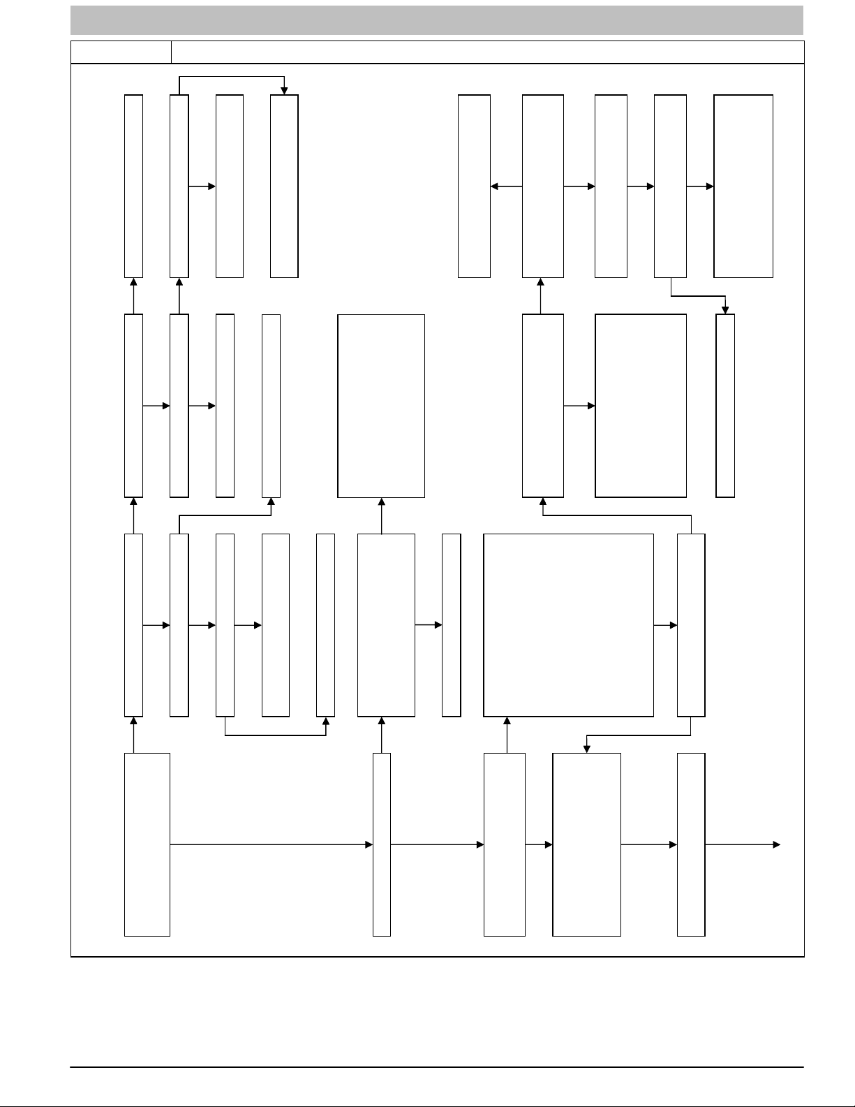
SERVICE AND TECHNICAL SUPPORT MANUAL Gas Furnace: (F/G)9MAE
g
Figure 16 Troubleshooting Chart − Flow Chart
NO
Guide
NO
NONO
NO
Close the door switch.
NO
Is circuit breaker closed?
Check for continuity in wire from circuit
breaker to furnace.
Close circuit breaker and go back to
START.
Check roomthermostat or
interconnecting cable.
Is 24V present at W/W1, W2, Y1, Y/Y2 or
NO
YES
Is doorswitch closed?
Isthere115Vgoingtoswitch?
NO
Replacedoor switch.
Replace transformer.
The control is locked out and will auto-
reset after 1 hour. Lockout could be due
to any ofthe following:
- Flame sense circuit failure.
- Gas valverelay stuck open.
-Softwarecheckerror.
Resetpower to clear lockout. Replace
controlif code repeats.
Does the control respond to W/W1, W2,
YES
YES
G thermostat terminals on the furnace
control?
Disconnectall the thermostatwires from
the furnace control.
YES
Y1, Y/Y2, and G (24V) thermostat
signals?
Run system through a minimum-heat,
maximum-heat, or cooling cycleto check
operation. Status codes are erased after
72 hours or can be manually erased by
putting setup switch SW1-1 in the ON
position and jumpering R, W/W1, and
NO
Does the problem repeat when using a
jumper wire?
The thermostat is not compatible with the
furnace control. Either install a ballast
resistor, connect the Com24Vthermostat
terminal to the thermostat, or replace the
thermostat.
YES
Y/Y2 simultaneously untilthe heartbeat
flashes.
Replace furnace control.
NO
Troubleshootin
YES
Is there 115V at L1 and L2?
Is there 24V at SEC-1 and SEC-2?
YES YES YES
YES
Is the 24V fuse open?
Replacefuse then disconnect thermostat
leads to isolate short circuit.
Replace furnace control.
Check to make sure that the correct
model plug PL4 is installed. The rating
NO
YES
YES
NO
The last status code has cleared. To
recalla previous statuscode disconnect
the R thermostat connection, reset
power,andputsetupswitchSW1-1in
the ON position. The AMBER LED will
flash the status codes in the order of
occurrence. Record status codes until
heartbeat flashes. After heartbeat
flashes several times the status codes
will repeat. Status codes are erased
after 72 hours or can be manually erased
by putting setup switch SW1-1 in the ON
position and jumpering R, W/W1, and
Y/Y2 simultaneously until the heartbeat
flashes. When done put setup switch
SW1-1 in the OFF position.
Was there a previous status code other
plate shows the correct model plug for
this furnace. Is the correct model plug
installed?
Replace model plug PL4.
YES
NO
NO
than theheartbeat?
YES
START
Is AMBER LED status light ON solid,
alternately flashing bright-dim-bright-dim
like a heartbeat, or flashing ON and
OFF?
Is AMBER LED status light ON solid?
Is AMBER LED status light alternately
flashing bright-dim-bright-dim like a
heartbeat?
Determine status code. The status code
is a single or two digit number with the
first number determined by the number of
short flashes and the second number
after the plus (+) sign is the number of
long flashes?
Go to section below for the status code
that was flashed.
440 04 4700 00 31
Specifications subject to change without notice.

SERVICE AND TECHNICAL SUPPORT MANUAL Gas Furnace: (F/G)9MAE
Figure 16 (CONT.) Troubleshooting Guide − Flow Chart
or rough ignition.
Replace furnace control.
Check for continuity in the
harness and igniter. Replace
defective component.
Check that all gas valves are
Check connections. If OK,
turned on. Replace valve.
replace control.
Check for:
- Inadequate flame carryover
bracket.
Allow unit to drop to min-heat,
- Low inletgas pressure.
- Proper firing rate.
- Air leakage around igniter
and check manifold pressure.
Check connections and retry.
If current is near typical value
(4.0-6.0 nominal) and burners
will not stay on, repeat check
in maximum-heat. If burners
will still not stay on replace
control. If burners operate in
maximum-heatthen switch to
intermediate-heat, check
manifoldpressure. If OK,
check burner carryover and
Repeat test to check for
intermittent operation.
flame sensor location.
YES
NO
failed to ignite gas and prove
flame in 4 attempts. Control will
auto-reset after 3 hours. Refer to
status code #6.
6 + 1 IGNITION LOCKOUT – System
(115V OR 24V) – Normal operation.
Blower runs for 90 seconds, if unit is
powered up during a call for heat (R-
W/W1 closed) or when (R-W/W1 opens)
during the blower on-delay period.
Unplug igniter harness from control and
repeat component test by turning setup
switch SW1-6 OFF and then back ON.
Check for 115V between pin 3 and
NEUTRAL-L2 on the control. Was 115V
Indicates the blower failedto reach 250
RPM or the blower failed to
communicate within 30 seconds after
beingturnedONintwosuccessiveheat
cycles. Control will auto-reset after 3
hours. Refertostatuscode#4+1.
NO
present for the 15 second period?
Reconnect the R thermostat lead and set
thermostatto call for heat. Connect
voltmeter across gas valve BLUE and
GREEN/YELLOW wires. Does gas valve
receive 24V?
SETUP ERROR – If status code 2 + 5
only flashes 4 times on power-up the
control is missing its model plug PL4
and is defaulting to the model selection
stored in memory. If status code 2 + 5
flashes continuously it could indicate
any of the following:
- Model plugPL4 is missing and there
NO
NO
YES
is no validmodel stored in permanent
memory. This will happenif you
YES
Does gas valve open and allow gas to
flow?
Dothemainburnersignite?
forget to install the model plug PL4 on
a servicereplacement control.
- Thermostat call with SW1-1 ON.
- Thermostat call with SW1-6 ON.
- SW1-1 and SW1-6 both ON.
- Two different furnace models
twinned.
YES
YES
Dothemainburnersstayon?
incorrect. Need modulating board
with software version V17 or later.
- Service replacement control is
modulatinggas valve failedto respond
NO
NO
YES
Clean flame sensor with fine steel wool
Repeat call for heat and check flame
sensor current during trial for ignition
period. Is the DC microamps below 0.5?
ORANGE wire at gas valve or PL8
to a command from the furnace control
connections.
or power to the gas valve electronics
was interrupted. Check for:
- Intermittent RED, YELLOW, or
and recheck current. Nominal current is
NO
NO
YES
YES
4.0to6.0microamps.
Is current near typical value? Replace electrode.
Will main burners ignite and stay on? Replace furnace control.
NO
Fixed.
YES
1+2 BLOWERONAFTERPOWERUP–
Check for:
- Obstructed pressure tube.
- Pressure switch stuck closed.
2 PRESSURE SWITCH DID NOT OPEN –
32 440 04 4700 00
3 LOW PRESSURE SWITCH DID NOT
1 + 5 BLOWER MOTOR LOCKOUT –
CLOSE OR REOPENED – If opens during
blower on-delay period, blower will come
on for the selected blower off-delay. If
opens within 5 minutes after ignition the
next heating cycle will be restricted to
maximum-heat. Check for:
2 + 5 INVALID MODEL SELECTION OR
71% of maximum
compartment.
tubing.
setupswitchSW1-3ONtoboost
inducer speed
-Properventsizing.
- Air leak between vestibule and blower
- Low inletgas pressure (if LGPS used).
- Restricted vent.
- Disconnected or obstructed pressure
- Defectiveor miswired pressure switches
- Excessive wind. If problem persists turn
Specifications subject to change without notice.
pipe.
- Plugged condensate drain.
- Water in vent piping, possible sagging
limit or a flame rollout switch is open or the
furnace is operating in maximum-heat only
mode due to 2 successive limit trips while
operating at any rate <
rate. Blower will run for 4 min. or until
open switch remakes whichever is longer.
4 LIMIT CIRCUIT FAULT – Indicates the
3 + 5 GAS VALVE FAULT – Indicates the
If openlonger than 3 min.,code changes
to lockout #7. If open less than 3 min.
status code #4 continues to flash until
blower shuts off. Flame rollout switch
gas input adjustment.
requires manual reset. Check for:
- Defective switch or connections.
- Improper minimum- or maximum-heat
- Improper limit switch or no limit gasket.
- Loose blower wheel.
Flame is proved while gas valve is de-
energized. Inducer will run until fault is
cleared. Check for:
- Dirty filter or restricted duct system.
- Stuck open or leaky gas valve.
5 ABNORMAL FLAME-PROVING SIGNAL
To determine whether the problem is in the gas
valve, igniter, or flame sensor the system can be
operated in component test mode. To check the
igniter remove the R thermostat connection from
the control, reset power, and put setup switch
SW1-6 in the ON position to start the
component test. Does the igniter glow
orange/white by the end of the 15 second warm-
not sensedduring the trialfor ignition
period, the control will repeat the ignition
sequence 3 more times before lockout #6 +
1 occurs. If flame signal is lost during the
blower on-delay period, blower will come on
for the selected blower off-delay. Check
6 IGNITION PROVING FAILURE – If flame is
the following before going to the next step.
connected to furnace sheet metal.
- Gas valveturned off.
- GREEN/YELLOW wire MUST be
- Manual shut-off valve.
up period?
- Flame sensormust not be grounded.
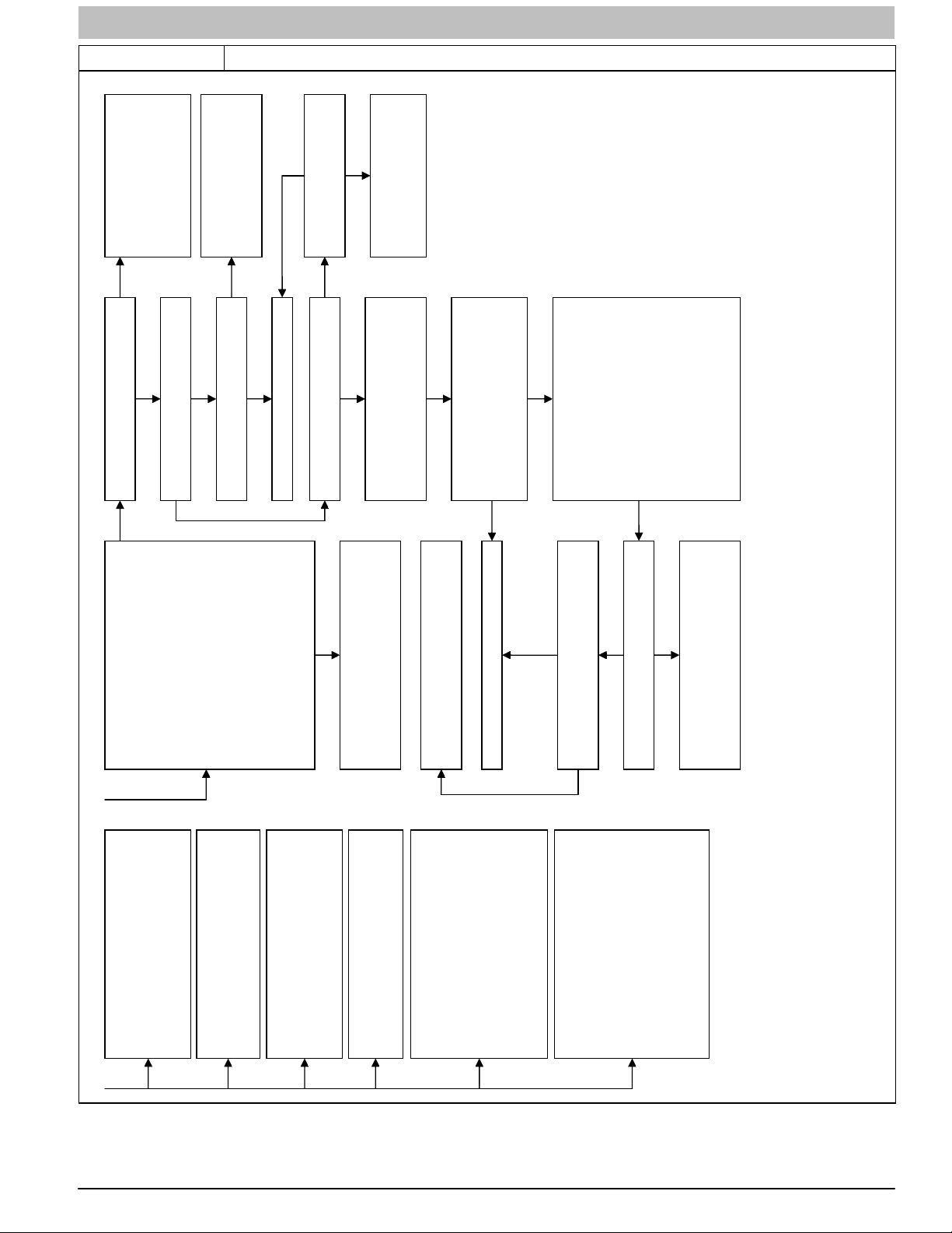
SERVICE AND TECHNICAL SUPPORT MANUAL Gas Furnace: (F/G)9MAE
Figure 16 (CONT.) Troubleshooting Chart − Flow Chart
NO
YES
NO
Youhaveanopenwireorbad
terminalon either theBLACK or
WHITE power leads between
the furnace control and the
blower motor. If you have a
power choke disconnect it and
check continuity.
Youhaveanopenwireorbad
terminal on either the RED or
GREEN wire between the
furnace control and the blower
motor.
YES
YES
Turn power back on. Is there 115VAC at
PL14-5 and PL14-4?
NO
Is there 12-VDC at PL13-1 RED (+) and
PL13-4 GREEN (-)?
NO
Is there 12-VDC at PL3-1 RED (+) and
PL3-2 GREEN (-)?
Replace the furnace control.
YES
Is there 5-VDC at PL3-3
NO
YES
YELLOW (+) and PL3-2
GREEN (-)?
Youhaveanopenwireorbad
terminal on the YELLOW wire
between the furnace control and
the blower motor.
YES
Is there 5-VDC at PL13-2 YELLOW (+)
and PL13-4 GREEN (-)?
The voltage just measured should be
very stable and should not fluctuate more
than .02-VDC. If the voltage fluctuates
more than this get a different voltmeter
before proceeding.
Turn poweroff, reconnect PL13 and
PL14 to the blower motor, then turn
power back on. Connect a DC voltmeter
NO
Turn power off, disconnect PL13 and
PL14 from the blower motor, then turn
power back on. Connect a DC voltmeter
across PL13-3 BLUE (+) and PL13-4
GREEN(-). Thevoltageshouldbenear
0-VDC but it will fluctuate briefly several
times a second. If you havean analog
voltmeter the needle will briefly go high
several times a second. If you have a
digitalvoltmeter with a bar graph it will
show alarge change in magnitude on the
bar graphseveral timesa second. If you
have a standard digital voltmeter it will
show a brief fluctuationin voltage and the
magnitude may vary depending on the
across PL3-3 YELLOW (+) and PL3-2
GREEN (-). Does the voltage fluctuate
more than it did in the previous step?
voltmeter used.
YES
4 + 1 BLOWER MOTOR FAULT – Indicates
7 LIMIT CIRCUIT LOCKOUT – Lockout
NO
theblowerfailedtoreach250RPMor
the blower failed to communicate within
the prescribed time limits. Thirty
seconds after being turned ON or ten
secondsduring steady-stateoperation.
Turn power off and check the following
items first before proceeding to the next
step.
motor.
- Rubbing blower wheel.
- Loose blower wheel.
- Wiring from furnace control to blower
Remove the R thermostat connection
from the furnace control, disconnect
both connectors from the blower motor
PL13 and PL14. Does the blower wheel
turn freely?
Replace the blower control module attached to
the blower motor. Follow theinstructionswith
the blower control module to make sure the
entire blower motor does not need to be
replaced.
You have an open wire or bad terminal on the
BLUE wirebetween the furnacecontrol and the
blowermotor.
Replace the furnace control.
NO
NO
Connect a DC voltmeter across PL3-4 BLUE
(+) and PL3-2 GREEN (-). Does the voltage
fluctuate as described two steps back?
YES
Does the voltage fluctuate as described in the
previous step?
Replace the blower control module attached to
the blower motor. Follow theinstructionswith
the blower control module to make sure the
entire blower motor does not need to be
replaced.
YES
tubing.
used).
the inducer motor has not started within
20 seconds after a callfor heat, the
inducer motor RPM is outside its valid
range ofoperation, or theinducer RPM
signal was lost for 5 seconds during
operation. Check for:
- Proper vent sizing.
- Failed inducer motor.
- Restricted combustion air supply.
- Impropermotor wiring.
SWITCH OPEN WHILE MEDIUM OR
HIGH PRESSURE SWITCH IS
CLOSED - Check for:
- Low or Med press. switch stuck open.
- Disconnected or obstructed pressure
PRESSURE SWITCH OR PSR RELAY
DID NOT CLOSE OR REOPENED -
Check for:
- PSR relay may be defective.
- Refer to status code #3.
voltage polarity. If units are twinned,
check for proper low-voltage(24V)
occurs if the limit or flame rollout switch is
open longer than 3 minutes or 10
successive limit trips occurred during
maximum-heat. Control willauto-reset
after 3 hours. Refer to status code #4.
NOT auto reset. Turn off powerand wait
5 minutes to retry. Check for:
- Stuck closed gas valve relay on control.
- Miswire or short to gas valve BLUE wire.
8 GAS HEATING LOCKOUT – Control will
9 MEDIUM PRESSURE SWITCH, HIGH
transformer phasing.
10 POLARITY – Check for correct line
4 + 2 INDUCER MOTOR FAULT – Indicates
4 + 3 LOW OR MEDIUM PRESSURE
- Improper pressure switch wiring.
pipe.
- Low inletgas pressure (ifLGPS
- Plugged condensate drain.
- Water in vent piping, possible sagging
440 04 4700 00 33
Specifications subject to change without notice.

SERVICE AND TECHNICAL SUPPORT MANUAL Gas Furnace: (F/G)9MAE
SEQUENCE OF OPERATION
!
CAUTION
UNIT OPERATION HAZARD
Failure to follow this caution may result in intermittent
unit operation.
Furnace control must be grounded for proper
operation or control will lock out. Control is grounded
through green/yellow wire routed to gas valve and
manifold bracket screw.
Using the schematic diagram (See Figure 15), follow the
sequence of operation through the different modes. Read and
follow the wiring diagram very carefully!!
NOTE: If a power interruption occurs during a call for heat
(W/W1 or W/W1-and-W2), the control will start a 90-second
blower-only ON period two seconds after power is restored, if
the thermostat is still calling for gas heating. The amber LED
light will flash code 1+2 during the 90-second period, after
which the LED flash a heartbeat (bright−dim), as long as no
faults are detected. After the 90-second period, the furnace will
respond to the thermostat normally.
The blower door must be installed for power to be conducted
through the blower door interlock switch ILK to the furnace
control CPU, transformer TRAN, inducer motor IDM, blower
motor BLWM, hot surface igniter HSI, and gas valve GV.
Communicating Control and Modulating Heating
(Adaptive Mode)
Best comfort will be attained when a communicating wall
control is used with this product. Wiring and setup instructions
are provided with the communicating control. See the furnace
data sheet accessory section for help in selecting the
appropriate communicating control for this furnace.
When a communicating control is used, the furnace will
modulate through its full operation range, or can be limited via
the minimum and maximum CFM capacity configurations.
Operation of the furnace at the beginning and end of each
heating cycle will be the same as detailed below in the
Single-Stage Thermostat section, EXCEPT that the
communicating control will send modulating rate command
signals through the communication bus rather than energizing
the 24−V thermostat terminals. Note that the R to W/W1 circuit
signal will be controlled by the COMMR relay on the furnace
control. See the wiring diagram in Figure 15.
Single-Stage Thermostat and Modulating Heating
(Adaptive Mode)
NOTE: Minimum-heat only switch SW1-2 selects the
minimum-heat only operation mode when ON.
Intermediate-heat only switch SW4-2 selects
intermediate-heat only operation mode when ON. If both
switches are ON the furnace control will default to
intermediate-heat. If either or both switches are ON, the furnace
control will operate at two-stages only as referenced in Two
Stage Thermostat section below. If both switches are OFF the
furnace control will operate in the adaptive heating mode in
response to a call for heat. (See Figure 15) When the W2
thermostat terminal is energized it will always cause
maximum-heat operation as long as the R to W circuit is
closed, regardless of the setting of the minimum-heat or
intermediate-heat only switches.
This furnace can operate as a modulating furnace with a
single-stage thermostat because the furnace control CPU
includes a programmed adaptive sequence of controlled
operation, which selects a modulated rate between minimumand maximum-heat. This selection is based upon the stored
history of the length of previous gas-heating periods of the
single-stage thermostat.
The furnace will start up in either intermediate-, or
maximum-heat. The furnace will transition and operate at
minimum-heat or the calculated modulating rate after starting
and operating for 45 seconds at intermediate-heat. The
furnace control CPU defaults to minimum-heat on the first
thermostat cycle and calculates the modulating rate that the
furnace should run at for 19 minutes on subsequent heat
cycles.
If the power is interrupted, the stored modulating rate is erased
and the furnace control will select intermediate-heat for 45
seconds, minimum-heat for 19 minutes and then switch to
maximum-heat, as long as the thermostat continues to call for
heat. The furnace control CPU then uses this information to
calculate the modulating rate the furnace will operate at on the
next heating cycle. If the calculated modulating rate is between
40% - 99% then the furnace control CPU will operate for 45
seconds at intermediate-heat, and then operate at the
calculated modulating rate for up to 19 minutes and then switch
to maximum-heat as long as the thermostat continues to call for
heat. If the calculated modulating rate is 100% then the
furnace control will only operate at maximum-heat until the
thermostat is satisfied.
The wall thermostat ”calls for heat”, closing the R to W circuit.
The furnace control CPU performs a self-check, verifies the
low, medium, and high pressure switch contacts LPS,MPS, and
HPS are open, then de-energizes the PSR relay to close the
NC contact.
1. Inducer Prepurge Period The furnace control CPU
turns on inducer motor IDM and slowly increases the
inducer motor speed. After the low pressure switch LPS
closes the furnace control CPU continues to increase the
inducer motor speed until the medium pressure switch
MPS closes. When the medium pressure switch MPS
closes, inducer motor RPM is noted by the furnace
control CPU, and a 25-second prepurge period begins.
The RPM is used to evaluate vent system resistance.
This evaluation is then used to determine the required
RPM necessary to operate the inducer motor during
pre-purge, the first 45 seconds of intermediate-heat, or
any modulating rate that the furnace will transition to after
the blower on-delay is completed.
NOTE: The heat cycle can start in either intermediate- or
maximum-heat. If a maximum-heat cycle is initiated, the
furnace control CPU will continue to increase the inducer
motor speed after the medium pressure switch MPS closes.
When the medium pressure switch closes, inducer motor RPM
is noted by the furnace control CPU, and a 25-second prepurge
period begins. The RPM is used to evaluate vent system
restriction. This evaluation is then used to determine the
required RPM necessary to operate the inducer motor in
maximum-heat pre-purge, or maximum-heat. The high
pressure switch HPS should be closed before ignition but the
furnace control ignores this input until after ignition occurs.
2. Igniter Warm-Up - At the end of the prepurge period, the
Hot-Surface Igniter HSI is energized for a 17-second
igniter warm-up period
3. Trial-For-Ignition Sequence When the igniter warm-up
period is completed the main gas valve relay contact
GVR closes to energize the gas valve solenoid GV. The
gas valve solenoid GV permits gas flow to the burners
where it is ignited. Five seconds after the GVR closes, a
2-second Flame-Proving period begins. The HSI igniter
will remain energized until flame is sensed or until the
2-second flame proving period begins.
4. Flame-Proving - When the burner flame is proved at the
flame-proving sensor electrode FSE, the furnace control
CPU begins the blower-ON delay period and continues
to hold the gas valve GV open. If the burner flame is not
proved within two seconds, the furnace control CPU will
34 440 04 4700 00
Specifications subject to change without notice.

SERVICE AND TECHNICAL SUPPORT MANUAL Gas Furnace: (F/G)9MAE
close the gas valve GV, and the furnace control CPU will
repeat the ignition sequence for up to three more
Trials-For-Ignition before going to Ignition-Lockout.
Lockout will be reset automatically after three hours, or
by momentarily interrupting 115 vac power to the
furnace, or by interrupting 24 vac power at SEC1 or
SEC2 to the furnace control CPU (not at W/W1, G, R,
etc.).
If flame is proved when flame should not be present, the
furnace control CPU will lock out of Gas-Heating mode
and operate the inducer motor IDM at full speed until
flame is no longer proved.
5. Inducer Speed Change - If the cycle starts in
intermediate-heat, the furnace control CPU reduces the
inducer speed slightly after flame sense. If cycle starts in
maximum-heat, the furnace control CPU increases the
inducer speed after flame sense.
6. Blower-On delay — If the burner flame is proven, the
blower-ON delay for intermediate-heat and
maximum-heat are as follows:
Intermediate-heat - 45 seconds after the gas valve GV
is opened the blower motor BLWM is turned ON at the
modulating heat airflow.
Maximum-heat - 25 seconds after the gas valve GV is
opened the BLWM is turned ON at maximum-heat
airflow.
Simultaneously, the humidifier terminal HUM and
electronic air cleaner terminal EAC-1 are energized and
remain energized throughout the heating cycle.
7. Switching from Intermediate-Heat to a Low Range
Input - If the furnace control CPU switches from
intermediate-heat to a low range input (low range input
is an input rate less than or equal to 51% of full rate),
the furnace control CPU will turn the blower ON or switch
to the modulating heat airflow, energize the PSR relay to
open the NC contact, and slowly decrease the inducer
motor speed to the desired inducer RPM.
Switching from a Intermediate-Heat to a Medium
Range Input - If the furnace control CPU switches from
intermediate-heat to a different medium range input
(medium range input is an input rate between 52% and
71% of full rate), the furnace control CPU will turn the
blower ON or switch to the modulating heat airflow, and
continue to maintain the inducer motor speed or change
it further if required.
Switching from a Intermediate-Heat to a High Range
Input - If the furnace control CPU switches from
intermediate-heat to a high range input (high range input
is an input rate greater than or equal to 72% of full
rate), the furnace control CPU will turn the blower ON or
switch to the modulating heat airflow, and increase the
inducer motor speed to the desired inducer motor RPM.
Switching from Low Range Input to Maximum-Heat -
If the furnace control CPU switches from a low range
input to maximum-heat, the furnace control CPU will
de-energize the PSR relay to close the NC contact and
slowly increase the inducer motor speed until the
medium pressure switch MPS closes. When the medium
pressure switch MPS closes the inducer motor RPM is
noted by the furnace control CPU. The RPM is used to
evaluate vent system resistance. This evaluation is then
used to determine the required RPM necessary to
operate the inducer motor at maximum-heat. The
blower motor BLWM will transition to maximum-heat
airflow five seconds after the furnace control CPU
switches from a low range input to maximum-heat. As
the inducer RPM increases, the high pressure switch
HPS should close.
Switching from Medium Range Input to
Maximum-Heat - If the furnace control CPU switches
from medium range input to maximum-heat, the furnace
control CPU will increase the inducer motor speed to the
maximum-heat inducer motor RPM. The blower motor
BLWM will transition to the maximum-heat airflow five
seconds after the furnace control CPU switches from a
medium range input to maximum-heat. As the inducer
RPM increases, the high pressure switch HPS should
close.
8. Blower-Off Delay — When the thermostat is satisfied,
the R to W circuit is opened, de-energizing the gas
valve GV, stopping gas flow to the burners, and
humidifier terminal HUM. The inducer motor IDM will
remain energized for a 15-second post-purge period.
The blower motor BLWM and air cleaner terminal
EAC-1 will remain energized at minimum-heat airflow or
transition to minimum-heat airflow for 90, 120, 150, or
180 seconds (depending on selection at blower-OFF
delay switches). The furnace control CPU is factory-set
for a 120-second blower- OFF delay.
Two-Stage Thermostat and Modulating Heating
(Adaptive Mode)
Operation of Modulating Heating (Adaptive Mode; SW1-2 and
SW4-2 are both OFF) with a two-stage thermostat is the same
as with a single-stage thermostat, EXCEPT for the following:
If the two-stage thermostat R to W2 circuit closes along with the
R to W/W1 circuit, while the furnace is operating at any
capacity less than maximum, the furnace will switch to the
maximum heating capacity. At this point, the furnace control
heating algorithm is overridden and the two-stage thermostat
takes control of staging until BOTH R to W/W1 and R to W2
circuits are opened.
The furnace will transition back to the lower heating capacity if
the two-stage thermostat opens the R to W2 circuit, but leaves
R to W/W1 circuit closed. The furnace control will continue to
follow the commands from the two-stage thermostat for W/W1
and W2, until the R to W/W1 circuit is opened.
After the two-stage thermostat opens both the R to W/W1 and
R to W2 circuits, the adaptive algorithm will set the beginning
capacity of the next heating cycle to the same value as the
heating cycle that most recently completed.
Two-Stage Thermostat and Two-Stage
Minimum/Maximum Heating
NOTE: In this mode, the minimum-heat only switch SW1-2
must be ON to select the minimum-heat only operation mode in
response to closing the thermostat R to W1 circuit. Closing the
thermostat R to W1-and-W2 circuits always causes
maximum-heat operation, regardless of the setting of the
minimum-heat only switch.
The furnace will start up in either intermediate-, or
maximum-heat. The furnace will operate in minimum-heat after
starting and operating for 1 minute at intermediate-heat before
transitioning to minimum-heat.
The wall thermostat ”calls for heat”, closing the R to W1 circuit
for minimum-heat or closing the R to W1-and-W2 circuits for
maximum-heat. The furnace control performs a self-check,
and verifies the low, medium and high pressure switch
contacts LPS, MPS and HPS are open, then de-energizes the
PSR relay to close the NC contact.
The start up and shut down functions and delays described
above apply to the two-stage minimum/maximum heating mode
as well, except for switching from maximum- to minimum-heat.
1. Switching from Maximum- to Minimum-Heat — If the
thermostat R to W2 circuit opens, and the R to W1 circuit
remains closed, the furnace control CPU will gradually
decrease the inducer motor speed to the required
intermediate-heat RPM. When the inducer motor IDM
reduces pressure sufficiently, the high pressure switch
440 04 4700 00 35
Specifications subject to change without notice.

SERVICE AND TECHNICAL SUPPORT MANUAL Gas Furnace: (F/G)9MAE
HPS will open and the gas rate will be changed to
intermediate-heat. The gas valve solenoid GV will remain
energized as long as the low pressure switch LPS
remains closed. When the inducer motor speed gets
within 15% of the required intermediate-heat RPM the
furnace control CPU will start a 5 second blower airflow
change delay. After the 5 second blower airflow change
delay is completed the blower airflow will transition to
minimum-heat airflow. At this point the furnace control
CPU will energize the PSR relay to open the NC contact
and slowly decrease the inducer motor speed to the
required minimum-heat RPM. When the PSR relay is
energized and the NC contact opens the furnace control
CPU will reduce the gas rate to minimum-heat RPM.
Two-Stage Thermostat and Two-Stage Intermediate/
Maximum Heating
NOTE: In this mode the intermediate-heat only switch SW4-2
must be ON to select the intermediate-heat only operation
mode in response to closing the thermostat R to W1 circuit.
Closing the thermostat R to W1-and-W2 circuits always
causes maximum-heat operation, regardless of the setting of
the intermediate-heat only switch.
The wall thermostat ”calls for heat”, closing the R to W1 circuit
for intermediate-heat or closing the R to W1-and-W2 circuits
for maximum-heat. The furnace control performs a self-check,
and verifies the low, medium and high pressure switch contacts
LPS, MPS and HPS are open , then de-energizes the PSR
relay to close the NC contact.
The start up and shut down functions and delays described
above apply to the 2-stage intermediate/maximum heating
mode as well, except for switching from maximum- to
intermediate-heat.
1. Switching from Maximum- to Intermediate-Heat — If
the thermostat R to W2 circuit opens, and the R to W1
circuit remains closed, the furnace control CPU will
gradually decrease the inducer motor speed to the
required intermediate-heat RPM. When the inducer
motor IDM reduces pressure sufficiently, the high
pressure switch HPS will open and the gas rate will be
changed to intermediate-heat. When the inducer motor
speed gets within 15% of the required intermediate-heat
RPM the furnace control CPU will start a 5 second
blower airflow change delay. After the 5 second blower
airflow change delay is completed the blower airflow will
transition to intermediate-heat airflow.
Cooling Mode
The thermostat “calls for cooling.”
1. Single-Speed Cooling
The thermostat closes the R to G-and-Y circuits. The R to Y
circuit starts the outdoor unit, and the R to G-and-Y/Y2 circuits
start the furnace blower motor BLWM on cooling airflow.
Cooling airflow is based on the A/C selection shown in
Figure 4, Table 3 and Table 6.
The electronic air cleaner terminal EAC-1 is energized with 115
vac when the blower motor BLWM is operating. When the
thermostat is satisfied, the R to G-and-Y circuits are opened.
The outdoor unit will stop, and the furnace blower motor BLWM
will continue operating at cooling airflow for an additional 90
seconds. Jumper Y/Y2 to DHUM to reduce the cooling off-delay
to 5 seconds. (See Figure 3).
Two−Stage Thermostat and Two-Speed Cooling
The thermostat closes the R to G-and-Y1 circuits for low
cooling or closes the R to G-and-Y1-and-Y2 circuits for high
cooling. The R to Y1 circuit starts the outdoor unit on low
cooling speed, and the R to G-and-Y1 circuit starts the furnace
blower motor BLWM at low-cooling airflow which is the true
on-board CF selection as shown in Figure 4, Table 3 and
Table 6. The R to Y1-and-Y2 circuits start the outdoor unit on
36 440 04 4700 00
Specifications subject to change without notice.
high-cooling speed, and the R to G-and-Y/Y2 circuits start the
furnace blower motor BLWM at high-cooling airflow.
High-cooling airflow is based on the A/C selection shown in
Figure 4, Table 3 and Table 6.
The electronic air cleaner terminal EAC-1 is energized with 115
vac whenever the blower motor BLWM is operating.
When the thermostat is satisfied, the R to G-and-Y1 or R to
G-and-Y1-and-Y2 circuits are opened. The outdoor unit stops,
and the furnace blower BLWM and electronic air cleaner
terminal EAC-1 will remain energized for an additional 90
seconds. Jumper Y1 to DHUM to reduce the cooling off-delay
to 5 seconds. (See Figure 3)
Dehumidification Mode
The dehumidification output, H on the Thermostat should be
connected to the furnace control thermostat terminal DHUM.
When there is a dehumidify demand, the DHUM input is
activated, which means 24 vac signal is removed from the
DHUM input terminal. In other words, the DHUM input logic is
reversed. The DHUM input is turned ON when no dehumidify
demand exists. Once 24 vac is detected by the furnace control
on the DHUM input, the furnace control operates in Thermostat
mode. If the DHUM input is low for more than 48 hours, the
furnace control reverts back to non-Thermostat mode.
The cooling operation described above in the Cooling Mode
section also applies to Dehumidification Mode. The exceptions
are listed below:
1. Low cooling – When the R to G-and-Y1 circuit is closed
and there is a demand for dehumidification, the furnace
blower motor BLWM will drop the blower airflow to 86%
of low cooling airflow which is the true on-board CF
selection as shown in Figure 4, Table 3 and Table 6.
2. High cooling – When the R to G-and Y/Y2 circuit is
closed and there is a demand for dehumidification, the
furnace blower motor BLWM will drop the blower airflow
to 86% of high-cooling airflow. High-cooling airflow is
based on the A/C selection shown in Figure 4, Table 3
and Table 6.
3. Cooling off-delay – When the “call for cooling” is
satisfied and there is a demand for dehumidification, the
cooling blower-off delay is decreased from 90 seconds
to 5 seconds.
Continuous Blower Mode
When the R to G circuit is closed by the thermostat, the blower
motor BLWM will operate at continuous blower airflow.
Continuous blower airflow selection is initially based on the CF
selection shown in Figure 4, Table 3 and Table 6. Factory
default is shown in Figure 4, Table 3 and Table 6. Terminal
EAC-1 is energized as long as the blower motor BLWM is
energized.
During a call for heat, the furnace control CPU will transition the
blower motor BLWM to continuous blower airflow,
minimum-heat airflow, or the mid-range airflow, whichever is
lowest. The blower motor BLWM will remain ON until the main
burners ignite then shut OFF and remain OFF for the
blower-ON delay (45 seconds in intermediate heat, and 25
seconds in maximum-heat), allowing the furnace heat
exchangers to heat up more quickly, then restarts at the end of
the blower-ON delay period at modulating or maximum-heat
airflow respectively.
The blower motor BLWM will revert to continuous-blower
airflow after the heating cycle is completed. When the
thermostat satisfies, the furnace control CPU will drop the
blower motor BLWM to minimum-heat airflow during the
selected blower-OFF delay period before transitioning to
continuous-blower airflow.
When the thermostat “calls for low-cooling”, the blower motor
BLWM will operate at low-cooling airflow. When the thermostat

SERVICE AND TECHNICAL SUPPORT MANUAL Gas Furnace: (F/G)9MAE
is satisfied, the blower motor BLWM will operate an additional
90 seconds at low-cooling airflow before transitioning back to
continuous-blower airflow.
When the thermostat “calls for high-cooling”, the blower motor
BLWM will operate at high cooling airflow. When the thermostat
is satisfied, the blower motor BLWM will operate an additional
90 seconds at high-cooling airflow before transitioning back to
continuous-blower airflow.
When the R to G circuit is opened, the blower motor BLWM will
continue operating for an additional 5 seconds, if no other
function requires blower motor BLWM operation.
Heat Pump
See Thermostat Instructions for thermostat connections. When
installed with a heat pump, the furnace control automatically
changes the timing sequence to avoid long blower off times
during demand defrost cycles. Whenever W/W1 is energized
along with Y1 or Y/Y2, the furnace control CPU will transition to
or bring on the blower motor BLWM at cooling airflow,
minimum-heat airflow, or the mid-range airflow, whichever is
lowest. The blower motor BLWM will remain on until the main
burners ignite then shut OFF and remain OFF for 25 seconds
before coming back on at modulating heat airflow. When the
W/W1 input signal disappears, the furnace control begins a
normal inducer post-purge period while changing the blower
airflow. If Y/Y2 input is still energized the furnace control CPU
will transition the blower motor BLWM airflow to cooling airflow.
If Y/Y2 input signal disappears and the Y1 input is still
energized the furnace control CPU will transition the blower
motor BLWM to low-cooling airflow. If both the Y1 and Y/Y2
signals disappear at the same time, the blower motor BLWM
will remain on at minimum-heat airflow for the selected
blower-OFF delay period. At the end of the blower-OFF delay,
the blower motor BLWM will shut OFF unless G is still
energized, in which case the blower motor BLWM will operate
at continuous blower airflow.
Component Self Test
Refer to page 22 for instructions.
440 04 4700 00 37
Specifications subject to change without notice.
SERVICE AND TECHNICAL SUPPORT MANUAL Gas Furnace: (F/G)9MAE
PARTS REPLACEMENT INFORMATION GUIDE
Casing Group
Control door
Blower door
Top filler plate
Bottom filler plate
Door Knob Assembly
Electrical Group
Control box
Junction box
Limit switch(es)
Circuit board
Door switch
Transformer
3−Amp fuse
Flame Rollout Switch
Main Wiring Harness
Blower Motor Harness (when used)
Filter Group
Filter(s)
Blower Group
Cut−off Plate
Blower housing
Blower motor
Blower wheel
Capacitor (when used)
Capacitor strap (when used)
Power choke (when used)
Gas Control Group
Manifold
Burner
Orifice
Flame sensor
Hot surface igniter
Gas valve
Heat Exchanger Group
Primary Heat Exchanger assembly
Primary Heat Exchanger cell panel
Secondary Heat Exchanger assembly
Coupling box
Containment Plate
Tubing Gaskets
Inducer Group
Pressure switch(es)
Inducer assembly
Inducer
Inducer motor
Motor Module (when used)
Inducer motor capacitor (when used)
Collector box
Condensate trap
Condensate trap elbow
Gaskets
WARNING
!
FIRE, EXPLOSION, ELECTRICAL SHOCK AND CARBON MONOXIDE POISONING HAZARD
Failure to follow this warning could result in dangerous operation, personal injury, death or property damage.
Improper installation, adjustment, alteration, service, maintenance, or use can cause carbon monoxide poisoning, explosion, fire,
electrical shock, or other conditions which may cause personal injury or property damage. Consult a qualified installer, service
agency, local gas supplier, or your distributor or branch for information or assistance. The qualified installer or agency must use only
factory-authorized and listed kits or accessories when modifying this product.
Have available the product/model number and the serial number located on the unit rating plate to ensure correct replacement parts.
TO OBTAIN INFORMATION ON PARTS: Consult your installing dealer or the classified section of your local telephone directory
under the “Heating Equipment“ or “Air Conditioning Contractors and Systems” headings for dealer listing by brand name.
38 440 04 4700 00
Specifications subject to change without notice.
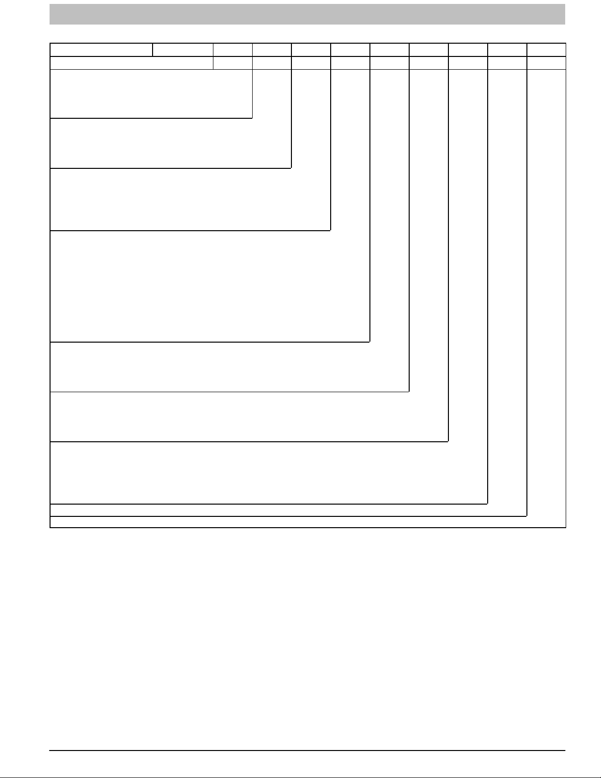
SERVICE AND TECHNICAL SUPPORT MANUAL Gas Furnace: (F/G)9MAE
PRODUCT NOMENCLATURE
DIGIT POSITION
G = Mainline Look 1
F = Mainline Look 2
N = Entry
9 = 90% − 100% EFFICIENCY
M = Multiposition
H = Horizontal
U = Upflow
D = Downflow
A = Modulating Variable Speed ECM
V = Variable Speed
X = ECM
S = Single−stage
T = Two−stage
B = Base AFUE Efficiency
E = Extra AFUE Efficiency
C = Communicating
D = Dual Certified 2−pipe or 1−pipe
R = 2−pipe only
S = Single−stage
T = Two−stage
N = Standard
L = Low Nox
060 = 60,000 BTU/hr
080 = 80,000 BTU/hr
100 = 100,000 BTU/hr
120 = 120,000 BTU/hr
14 = 14−3/16”
17 = 17−1/2”
21 = 21”
24 = 24−1/2”
10 = 1000 CFM (max)
14 = 1400 CFM (max)
16 = 1600 CFM (max)
20 = 2000 CFM (max)
22 = 2200 CFM (max)
SALES (MAJOR) REVISION DIGIT
ENGINEERING (MINOR) REVISION DIGIT
1 2 3 4 5 6, 7, 8 9, 10 11, 12 13 14
G
9 M A E 060 17 14 A 1
FEATURE
FEATURE
FEATURE
INPUT HEAT
CABINET WIDTH
COOLING AIRFLOW
International Comfort Products, LLC
Consumer Relations Department
P.O. Box 128
Lewisburg, TN 37091, USA
931−270−4100
440 04 4700 00 39
Specifications subject to change without notice.
 Loading...