

International Comfort Products DNPWREXH030A01, DNPWREXH022A01, DNPWREXH023A01 Installation Manual
Installation Instructions
ACCESSORY VERTICAL POWER EXHAUST, GAS HEATING/ELECTRIC COOLING,
ELECTRIC COOLING, AND HEAT PUMP UNITS
3 TO 121/2 TON
DNPWREXH030A01, DNPWREXH021A01, DNPWREXH022A01
DNPWREXH023A01, DNPWREXH080A00, DNPWREXH081A00
For Use With Vertical Economizer
TABLE OF CONTENTS
PACKAGE CONTENTS 1............................
UNIT CONFIGURATION TABLE 1....................
PACKAGE USAGE 1................................
SAFETY CONSIDERATIONS 1.......................
GENERAL 1........................................
INSTALLATION 2...................................
Power Exhaust Wiring with Economizer 3.............
Attaching Power Exhaust to the Unit 7................
Install Hinged Door Angle (Small and Large Cabinet) 8...
IMPORTANT: Read these instructions completely before
attempting to install the accessory power exhaust.
PACKAGE CONTENTS
QTY CONTENTS
1 Power Exhaust Hood/Fan Assembly
Low Voltage Wiring Harness with plug and 12 in (305mm)
1
gray jumper wire
1 High Voltage Wiring Harness with plug
8 No. 10 x 3/
1 Gasketing Roll
1 Sealing Angle
NOTES:
1. Both wiring harnesses are shipped attached to the power
exhaust assembly.
1
in. (19mm) Mounting Screws
4
1
1
UNIT CONFIGURATION TABLE
UNIT
CONFIGURATION
Small Cabinet 46 3/4” x 74 3/8”
Large Cabinet 58 1/2” x 88 1/8”
Extra Large Cabinet 63 3/8” x 115 7/8”
UNIT
FOOTPRINT SIZE
PACKAGE USAGE
UNIT
CONFIGURATION
Small Cabinet
Large Cabinet
Extra Large
Cabinet
NOTE: For 575−v installations, a field−supplied and installed transformer
(FAST part no. 1171494) must be used with 208/230 V power exhaust.
POWER EXHAUST
PART NUMBER
DNPWREXH030A01
DNPWREXH021A01
DNPWREXH022A01
DNPWREXH023A01
DNPWREXH080A00
DNPWREXH081A00
POWER EXHAUST
VOLTAGE
208/230 V,1 Ph
460 V, 3 Ph
208/230 V, 1 Ph
460 V, 3 Ph
208/230 V, 1 Ph
460 V, 3 Ph
SAFETY CONSIDERATIONS
Installation and servicing of air−conditioning equipment
can be hazardous due to system pressure and electrical
components. Only trained and qualified service personnel
should install, repair, or service air-conditioning equipment.
Untrained personnel can perform the basic maintenance
functions. All other operations should be performed by
trained service personnel. When working on
air-conditioning equipment, observe precautions in the
literature, tags and labels attached to the unit, and other
safety precautions that may apply.
Follow all safety codes. Wear safety glasses and work
gloves.
Recognize safety information. This is the safety−alert
symbol . When you see this symbol on the unit and in
instructions or manuals, be alert to the potential for
personal injury.
Understand the signal words DANGER, WARNING, and
CAUTION. These words are used with the safety−alert
symbol. DANGER identifies the most serious hazards
which will result in severe personal injury or death.
WARNING signifies a hazard which could result in
personal injury or death. CAUTION is used to identify
unsafe practices which may result in minor personal injury
or product and property damage. NOTE is used to
highlight suggestions which will result in enhanced
installation, reliability, or operation.
GENERAL
The accessory vertical power exhaust is used in
conjunction with the vertical Economizer accessories. For
horizontal applications, this power exhaust accessory
cannot be used. The horizontal power exhaust accessory
must be used for horizontal applications.
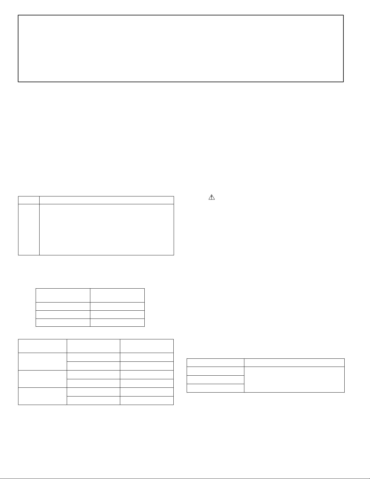
See Table 1 for Economizer usage. See Fig. 1 for
dimensions.
Table 1 – Accessory Vertical Economizer Use
PART NO. DESCRIPTION
DNECOMZR020A02
DNECOMZR021A03
DNECOMZR062A00
Economizer with
W7212 controller.
509 06 2302 01
8/22/11
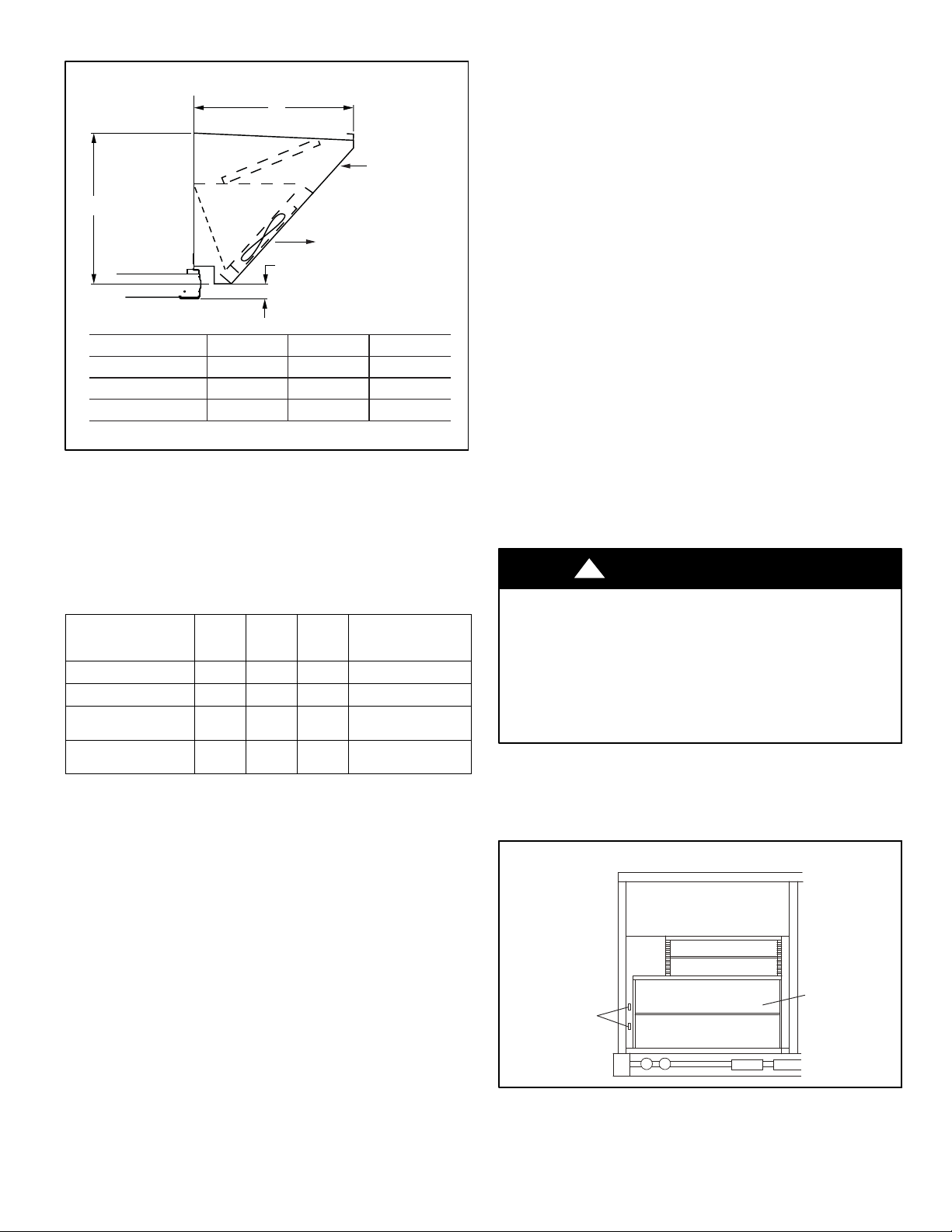
Fig. 1 − Dimensions, Economizer with Power Exhaust
X
ECONOMIZER
INLET
Y
POWER EXHAUST
OUTLET
Z
UNIT
CONFIGURATION
Small Cabinet
Large Cabinet
Extra-Large Cabinet
NOTE: Measurements are in inches (mm)
X
18.5 (470)
26 (660)
28.6 (725)
Y
19.25 (515)
25 (635)
37.75 (960)
Z
7
(11)
16
/
0 (0)
4.5 (115)
INSTALLATION
IMPORTANT: Follow all applicable local and national elec-
trical codes when installing this accessory.
Follow all local and NEC (National Electrical Code) codes.
If a single power source is to be used, size the wire to
include power exhaust MCA and MOCP. (See Table 2.)
Table 2 – Power Exhaust Electrical Data
POWER EXHAUST
PART NO.
DNPWREXH030A01
DNPWREXH021A01
DNPWREXH022A01
DNPWREXH080A00
DNPWREXH023A01
DNPWREXH081A00
LEGEND
MCA - Minimum Circuit Amps
MOCP- Maximum Overcurrent Protection
N/A - Not Applicable
MCA
(230 v)
N/A 0.9 N/A 15
N/A 1.8 N/A 15
MCA
(460 v)
1.5 N/A 0.64 15
3.3 N/A 1.32 15
MCA
(575 v)
NOTE: For R−410A units, refer to unit nameplate for MCA
and MOCP for installed power exhaust. For R−22 units,
use the calculations detailed below.
MOCP
(for separate
power source)
Check MCA and MOCP when power exhaust is powered
through the unit (must be in accordance with NEC and/or
local codes). Determine the new MCA including the power
exhaust using the following formula:
MCA New = MCA unit only + MCA of Power Exhaust
For example, using a R−22 gas heat, electric cooling,
6−ton unit with MCA = 28.9 and MOCP = 35, with
DNPWREXH030A01 power exhaust.
MCA New = 28.9 amps + 1.5 amps = 30.4 amps
If the new MCA does not exceed the published MOCP,
then MOCP would not change. The MOCP in this example
is 35 amps, the MCA New is below 35, therefore the
MOCP is acceptable. If “MCA New” is larger than the
published MOCP, raise the MOCP to the next larger size.
For separate power, the MOCP for the power exhaust will
be 15 amps per NEC.
NOTE: For 575−v installations, a field−supplied and
installed transformer (FAST part no. 1171494) must be
used with 208/230−v power exhaust. (See Fig. 6.)
The vertical power exhaust can be used with the following
type of economizer
S Economizer with controller W7212.
To install the vertical power exhaust, perform the
following procedure:
1. Turn off unit power supply and install lockout tag. For
gas units, turn off the gas supply.
!
WARNING
ELECTRICAL SHOCK HAZARD
Failure to follow this warning could cause personal injury
and/or death.
Before beginning any modification, be certain the
main−line electrical disconnect switch is in the OFF
position. Close the main gas supply shutoff valve. Tag
disconnect switch and gas valve with suitable warning
labels.
NOTE: Before installing, ensure voltage of power exhaust
agrees with power supply to the equipment.
2. Remove the power exhaust knockout plugs located on
the lower left side of the Economizer. (See Fig. 2.)
Fig. 2 − Power Exhaust Knockout Location
509 06 2302 01
ECONOMIZER
POWER
EXHAUST
KNOCKOUTS
2
3. Remove the RTU unit filter panel to allow access to the
inside of the rooftop.
4. The panel covering the horizontal return opening on
the unit may also be removed for easier access and
installation. Be sure to replace this panel when installation is complete.
5. Install the vertical economizer per the instructions
provided with the economizer. Do not install the rainhood shipped with the Economizer. Set aside the aluminum air filter for use with the power exhaust.
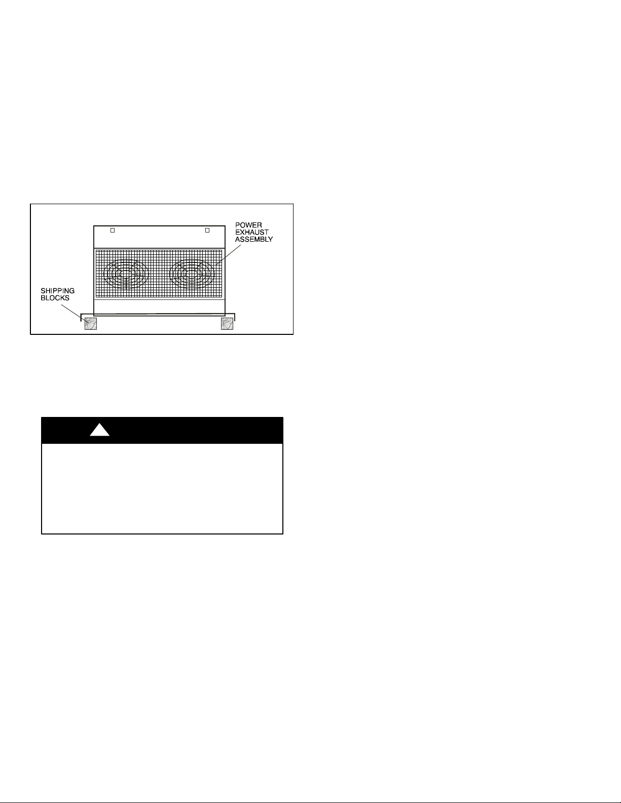
6. Remove fan shield so power exhaust can lay flat
without bending the shield or damaging the roof.
7. Remove the shipping blocks from the bottom of the accessory vertical power exhaust. (See Fig. 3.)
Fig. 3 − Shipping Block Removal
8. There may be a hinged door panel in place of the filter
panel. Open the hinged door, remove the screws and
hinges, remove the door and set it aside. Keep all
screws and hinges.
9. Place the power exhaust close to the Economizer to
allow for wiring harness connection.
!
CAUTION
UNIT DAMAGE HAZARD
Failure to follow this caution may result in
equipment damage.
Be careful to route wires to avoid pinching or
cutting during assembly. It can be difficult to
protect the wires while attaching the power
exhaust to the unit.
10. Follow the wiring instructions specific to the Economizer. Be sure power exhaust wiring does not interfere
with damper operation.
Power Exhaust Wiring with Economizer
Use these instructions and diagrams if using the vertical
power exhaust with Economizer.
1. The 2−wire low voltage harness from the power ex-
haust and the 24 or 36 in (610 or 915 mm) low voltage
extension harness are plugged together for shipping.
Unplug these 2 harnesses for installation.
2. Insert the 2−wire low voltage harness plug from the
power exhaust into the top knockout on the economizer. (See Fig. 2.)
3. From the rear of the economizer, connect the 24 in
(610) long low voltage extension harness plug to the
power exhaust harness.
4. Route the other end of the low voltage extension harness to the economizer controller. (See Fig. 4.) The
harness is connected to the controller by connecting
the tan wire to the tan wire 24 VAC COM terminal on
the controller. The terminal on the gray wire is connected to terminal EF1 on the controller. See Fig. 5 and 6
for economizer wiring diagrams. Install the gray jumper
wire on the controller from the exhaust fan terminal
(EF), to the 24 VAC HOT terminals. The gray jumper is
shipped wire tied to the control harness.
5. The high voltage harness from the power exhaust and
the high voltage extension harness are plugged together
for shipping. Unplug these 2 harnesses for installation.
6. Insert the high voltage harness plug from the power
exhaust into the bottom knockout on the economizer.
(See Fig.2 and 4.)
R−410A Rooftop Models Only — For single point
wiring application, connect the power exhaust power
wire harness to the compressor contactor or indoor fan
contactor in the control box. Install the power exhaust
power wire harness into the pressure lugs on the
compressor contactor or indoor fan contactor, used for
the field power wiring also.
Proceed to steps 7 and 8 for details on completing
connection and routing.
7. From the rear of the economizer, connect the long high
voltage extension harness plug to the power exhaust
harness. (See Fig. 4.)
8. Route the other end of the long high voltage extension
harness through the HVAC unit to the control box.
(See Fig. 5.) The harness must be routed through the
grommets provided in the unit. Do not drill routing
holes. Be careful not to route the power exhaust
harness on top of the indoor coil. Wire the end of the
high voltage harness extension to the power exhaust
power source. (See Fig. 6 and 7.)
3
509 06 2302 01

Fig. 4 − Power Exhaust Harness Installation for Economizer with W7212 Controller
COIL
FILTERS
HVAC UNIT
W7212
CONTROLLER
24−IN (610mm)
LOW VOLTAGE
EXTENSION
HARNESS
ECONOMIZER
Cover panel
over
horizontal
return
2−WIRE
LO W
VOLTAGE
HARNESS
ECONOMIZER/POWER
EXHAUST
OUTDOOR AIR HOOD
134−IN. (3406mm)
OR 194−IN. (4928mm)
HIGH VOLTAGE
EXTENSION HARNESS
Fig. 5 − Power Line Harness Routing (Top View of Unit Shown)
MAIN POWER
Note 1
KNOCKOUTS
UNIT ROOF CURB
HIGH VOLTAGE
HARNESS
ROOF
HIGH & LOW VOLTAGE WIRING HARNESS
ECONOMIZER
Low Voltage Harness
note 1
FILTER
COIL
High Voltage
Harness
INDOOR
FAN
POWER EXHAUST
(INSTALLED POSITION)
509 06 2302 01
Field supplied
connectors
RTU CONTROL
BOX
note 1
Note: Ensure main power line, disconnect, and fuse/breaker are sized per National Electric Guide.
4

Fig. 6 − Power Exhaust Wiring for Economizer with Controller W7212 — 208/230 V and 575 V Units
FIELD
POWER
SUPPLY
BLK
YEL
BLU
GRN/YEL
To C11 for Small and Large Cabinet
To IFC−11 for Extra−Large Cabinet
To C13 for Small
and Large Cabinet
To IFC13 for
Extra−Large Cabinet
GRD.
POWER LINE
PLUG
3
1
2
4
OR
FIELD SUPPLIED
2 X 4 JUNCTION BOX
GROUND
FOR 575−V POWER SUPPLY
FOR 208/230−V SEPARATE
POWER SUPPLY
GREEN − YELLOW
C1
GREEN − YELLOW
BROWN
GRD.
13
4
79
AB
REL AY
NOTES:
1
2
3
4
BL ACK
BL ACK
GREEN
3
BL ACK
1
RED
2
4
3
1
2
4
TO 575V POWER
575V
PRIMARY
SECONDARY
220V
RED
EXH.
FA N #1
TRANSFORMER
No. 1171494
Field Supplied
AND INSTALLED)
BL ACK
BLUE
C2
BL ACK
BL ACK
6
BLUE
EXH.
FAN #2
TO ECONOMIZER
ACTUATOR
BROWN
END
SWITCH
PLUG
TA N
1
2
3
GRAY GRAY
4
TA N
TA N
1
2
3
4
3
Field Supplied Wiring
575 V transformer No. 1171494 is ordered
separately from power exhaust.
Economizer actuator and controller are shipped with
the Economizer − not with power exhaust.
Connections from End Switch plug to Economizer
controller are made by installer.
If a single power source is to be used, size wire to
include power exhaust MCA and MOCP.
For R−410A units, refer to unit nameplate for MCA
and MOCP for installed power exhaust.
WHITE
GRAY
BL ACK
RED
POWER
EXHAUST
ACCESSORY
2
ECONOMIZER
CONTROLLER
24 VAC
HOT
24 VAC
COM
+
EF 1
EF
2
For R−22 units, use the following calculations
Check MCA and MOCP when power exhaust is powered
through the unit. Determine the new MCA including the
FIELD
SUPPLIED
FUSED
DISCONNECT
power exhaust using the following formula:
MCA New = MCA unit only + MCA of Power Exhaust
For example, using an electric cooling, 6−ton
R−22 unit with MCA + 28.9 and MOCP = 35, with
DNPWREXH030A01 power exhaust.
MCA New = 28.9 amps + 1.5 amps = 30.4 amps
If the new MCA does not go over the MOCP published,
then MOCP would not change. The MOCP in this
example is 35 amps, the MCA New is below 35,
therefore the MOCP is OK. If “MCA New” is larger than
the published MOCP, raise the MOCP to the next
larger size. For separate power, the MOCP for the
power exhaust will be 15 amps per NEC.
C10426
5
509 06 2302 01

Fig. 7 − Power Exhaust Wiring for Economizer with Controller W7212 — 460 V Units
FIELD
POWER
SUPPLY
BLK
YEL
BLU
GRN/YEL
To C11 for Small and
Large Cabinet
To IFC−11 for
Extra−Large Cabinet
To C13 for Small
and Large Cabinet
To IFC13
for Extra−Large
Cabinet
EQUIP
GND
GREEN
GROUND
FIELD
SUPPLIED
FUSED
DISCONNECT
SEPARATE
POWER
SOURCE
BL ACK
RED
WHITE
POWER
FIELD SUPPLIED
2 x 4 JUNCTION BOX
BL ACK
LINE
PLUG
1
2
3
4
OR
GREEN − YELLOW
GRAY
GRAY
BLUE
BROWN
REL AY #1
3
23
5
6
9
8
B
WHITE
WHITE
GRD
BL ACK
FAN #2
BL ACK
112
4
7
A
4
7
A
1
2
3
4
EXH.
FAN #1
BL ACK
RED
GREEN
EXH.
BROWN
5
8
GRAY
GRAY
BLUE
REL AY #2
6
9
B
TA N
GRAY
POWER
EXHAUST
ACCESSORY
1
END
SWITCH
PLUG
1
4
TO ECONOMIZER
ACTUATOR
TA N
1
22
GRAY
33
GRAY
4
2
Field Supplied Wiring
1
2
3
4
NOTES:
Economizer actuator and controller are shipped with the Economizer
1
not with power exhaust.
Connections from End Switch Plug to the Economizer controller are made
2
by installer.
If a single power source is to be used, size wire to include power exhaust
3
MCA and MOCP.
For R−410A units, refer to the unit nameplate for MCA and MOCP for
installed power exhaust.
For R−22 units use the following calculations
Check MCA and MOCP when power exhaust is powered through the unit.
Determine the new MCA including the power exhaust using the following
formula:
MCA New = MCA unit only + MCA of Power Exhaust
For example, using an electric cooling, 6−ton R−22 unit with MCA = 28.9 and
MOCP = 35, with DNPWREXH030A01 power exhaust.
MCA New = 28.9 amps + 1.5 amps = 30.4 amps
If the new MCA does not go over the MOCP published,
then MOCP would
not change. The MOCP in this example is 35 amps, the MCA New is below
35, therefore the MOCP is OK. If “MCA NEW” is larger than the published
MOCP, raise the MOCP to the next larger size. For separate power, the
MOCP for the power exhaust will be 15 amps per NEC.
BL ACK
WHITE
TA N
ECONOMIZER
CONTROLLER
RED
24V
HOT
24V
COM
+
EF
1
EF 1
C10427
509 06 2302 01
6

Attaching Power Exhaust to the Unit
1. Make sure all power exhaust harnesses are connected
as indicated in the previous steps. See Fig. 6 and 7 for
Economizer.
2. Make sure all wiring is secure. Use field−supplied wire
ties if necessary. Be sure that wiring does not interfere
with operation of the HVAC unit, economizer, or power
exhaust.
3. For units with a standard filter panel (i.e., no hinged
door): Install the gasketing (provided) on the back of
power exhaust side mating flanges. (See Fig. 8)
NOTE: This step does not apply to units with a hinged
door.
Fig. 8 − Gasketing Location Detail
(Standard Filter Panel Only)
UNIT CORNER
POST
GASKETING
POWER
EXHAUST
4. Lift power exhaust and install over economizer using
the #10 x 3/4 in. long screws provided. Make sure wiring harnesses are properly secured. (See Fig. 9)
Fig. 9 − Power Exhaust Installed on Unit
ALUMINUM
CONTROLLER
FILTER
POWER
EXHAUST
5. Locate the aluminum filter shipped with the economizer. Open the filter clips under the top hood of the
power exhaust. Slide aluminum filter into the outside
air opening of the power exhaust. Filter will slide past
filter clips. Close filter clips, which will lock filter in
place.
6. Reinstall the fan shield.
7. Return power to unit and remove lockout tag.
8. Test power exhaust operation by setting the power exhaust set point on the economizer controller to 0%.
Power exhaust performance is shown in Fig. 10.
9. Adjust the power exhaust set point on the Economizer
controller to the desired activation point per unit
schematic.
10. For units with a standard filter access panel, reinstall
the unit filter access door.
For units with a hinged access door (Small & Large
Cabinet), install the hinged door seal angle included in
the power exhaust kit using the instructions in this
instruction. Do not proceed unless the sealing angle is
installed. Units with a hinged door that do not have a
sealing angle may not have a watertight seal.
Fig. 10 − Power Exhaust Performance
5000
4000
3000
EXHAUST
2000
AIRFLOW (cfm)
1000
0
0 0.1 0.2 0.3 0.4 0.5
RETURN DUCT STATIC PRESSURE (in wc)
Small Cabinet
Large and
Extra-Large
Cabinet
7
509 06 2302 01

Install the Hinged Door Angle
(Small and Large Cabinet)
Follow these instructions if the unit has a hinged panel
instead of a standard filter panel. Hinged Door Angle
DNPECONV003A00 is for 3 to 5 ton units and
DNPECONV004A00 is for 6 to 10 ton units.
1. Find the sealing angle and three screws provided in
the power exhaust kit.
2. Attach the sealing angle to the top of the power exhaust hood using the screws provided. Refer to Fig.
14. Note that the gasketing flange will be facing out.
3. If there are NO pre−drilled holes in the Power Exhaust
hood: Lay the hinged panel, insulation side up, on top
of the hood so that the hinge screw holes align with
the pre−drilled screw holes in the sealing angle. (For
hoods with pre−drilled holes, skip to Step 7.)
4. Check the alignment of the hinged door with the side
of the filter opening to be sure it will close properly.
5. Use a pencil to mark the hood where the screw holes
will be.
6. Remove the hinged door and drill four (4) 11/64 in.
holes where the marks are.
Fig. 11 − Power Exhaust Installation
Fig. 12 − Install Sealing Angle
SEE
NOTE
SEE
NOTE
GASKETED
FLANGE
SEALING
ANGLE
Fig. 13 − Re−Install the Hinged Door
SEALING ANGLE
POWER EXHAUST HOOD
SCREW ANGLE
TO HOOD (3)
HINGED DOOR
GASKET
LOCATION
(STANDARD
FILTER
PAN E L
ONLY)
POWER EXHAUST
SIDE FLANGES
GASKET LOCATION
NOTE: The sealing angle will be in place; use the holes in
it as a guide.
7. Place the door and hinges back on the unit. Screw
through the door hinges and sealing angle into the
flanged top of the hood using the 4 screws set aside
when the hinged door was removed. (See Fig. 13.)
8. Close the hinged door and adjust handles if necessary.
509 06 2302 01
8
 Loading...