

International comfort products DLCBHR, DLFAHH, DLFBHB, DLFBHC, DLFBHF Installation Instructions Manual
...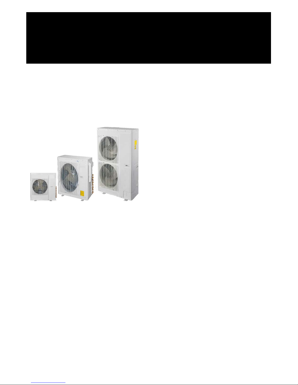
DLCBHR / DLFAHH / DLFBHB / DLFBHC / DLFBHD / DLFBHF
Multi- Zone Ductless Split System
Size 18K, 24K, 30K, 36K, 42K, 48K and 56K
Installation Instructions
NOTE: Read the entire instruction manual before starting the installation.
TABLE OF CONTENTS
SAFETY CONSIDERATIONS 2.........................
PAGE
GENERAL 2.........................................
SYSTEM REQUIREMENTS 3- 4.........................
ELECTRICAL DATA 4................................
PARTS LIST 6........................................
DIMENSIONS 7- 14...................................
CLEARANCES 15- 17.................................
DIMENSIONS - BRANCH BOXES 18- 19.................
INSTALLATION GUIDE 20.............................
HIGH- WALL INDOOR UNIT INSTALLATION 20..........
DUCTED INDOOR UNITS INSTALLATION 21............
FLOOR CONSOLE INDOOR UNITS INSTALLATION 24....
INSTALLING THE INDOOR UNIT 26....................
CASSETTE TYPE INDOOR UNIT INSTALLATION 28......
OUTDOOR UNIT INSTALLATION 31....................
SYSTEM VACUUM AND CHARGE 35...................
START- UP 37........................................
TROUBLESHOOTING 38- 41...........................

SAFETY CONSIDERATIONS
Installing, starting up, and servicing air- conditioning equipment
can be hazardous due to system pressures, electrical components,
and equipment location (roofs, elevated structures, etc.).
Only trained, qualified installers and service mechanics should
install, start-up, and service this equipment.
Untrained personnel can perform basic maintenance functions such
as cleaning coils. All other operations should be performed by
trained service personnel.
When working on the equipment, observe precautions in the
literature and on tags, stickers, and labels attached to the
equipment.
Follow all safety codes. Wear safety glasses and work gloves. Keep
quenching cloth and fire extinguisher nearby when brazing. Use
care in handling, rigging, and setting bulky equipment.
Read these instructions thoroughly and follow all warnings or
cautions included in literature and attached to the unit. Consult
local building codes and current editions of the National Electrical
Code ( NEC ) NFPA 70. In Canada, refer to current editions of the
Canadian electrical code CSA 22.1.
!
Recognize safety information. This is the safety- alert symbol
When you see this symbol on the unit and in instructions or
manuals, be alert to the potential for personal injury. Understand
these signal words: DANGER, WARNING, and CAUTION.
These words are used with the safety- alert symbol. DANGER
identifies the most serious hazards which will result in severe
personal injury or death. WARNING signifies hazards which could
result in personal injury or death. CAUTION is used to identify
unsafe practices which may result in minor personal injury or
product and property damage. NOTE is used to highlight
suggestions which will result in enhanced installation, reliability, or
operation.
!
!
ELECTRICAL SHOCK HAZARD
Failure to follow this warning could result in personal
injury or death.
Before installing, modifying, or servicing system, main
electrical disconnect switch must be in the OFF
position. There may be more than 1 disconnect switch.
Lock out and tag switch with a suitable warning label.
!
EQUIPMENT DAMAGE HAZARD
Failure to follow this caution may result in equipment
damage or improper operation.
Do not bury more than 36 in. (914 mm) of refrigerant pipe
in the ground. If any section of pipe is buried, there must be
.
a 6 in. (152 mm) vertical rise to the valve connections on
the outdoor units. If more than the recommended length is
buried, refrigerant may migrate to the cooler buried section
during extended periods of system shutdown. This causes
refrigerant slugging and could possibly damage the
compressor at start- up.
WARNING
CAUTION
GENERAL
These instructions cover the inst allati on, start-up and servic i ng of the
multi-zone outdoor unit connec t ed to up to nine indoor fan coil units .
For approved combinations, please refer to the Product Data.
2
SYSTEM REQUIREMENTS
Allow sufficient space for airflow and servicing unit. See Fig. 14 through 19 for minimum required clearances.
Piping
IMPORTANT: Both refrigerant lines must be insulated separately.
Minimum refrigerant line length between the indoor and outdoor units is 10 ft. (3 m). The following maximum lengths are allowed:
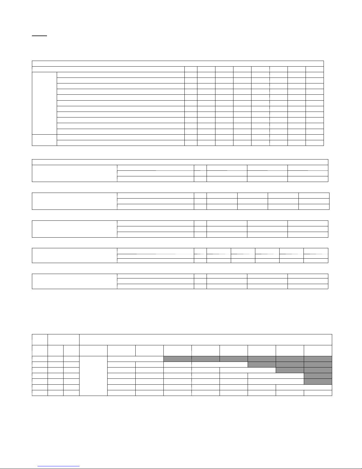
Table 1—Maximum Piping Lengths
System Size 18 24 30 36 42 48 56
Piping
Refrigerant
Min. Piping Length ft 10 10 10 10 10 10 10
Standard Piping Length ft 32 98 131.2 131.2 131.2 98.42 98.42
Max. outdoor-indoor height difference ft 33 33 49.2 49.2 49.2 98.42 98.42
Max. height distance between indoor and indoor ft 33 33 24.6 24.6 24.6 49.21 49.21
Max. height distance between indoor and outdoor and indoor ft 32 32 49.2 49.2 49.2 98.42 98.42
Max. height distance between indoor and outdoor and outdoor up ft 33 33 49.2 49.2 49.2 98.42 98.42
Max. equivalent piping outdoor to last indoor ft 33 65 82 82 82 229 229
Max. Piping Length with no additional refrigerant charge ft 32 98 131.2 131.2 131.2 98.42 98.42
Max. Piping Length ft 65 196 229.7 246 246 442.9 475.7
Gas Pipe (size - connection type) in 3/8 3/8 3/8 3/8 3/8 5/8 5/8
Liquid Pipe (size - connection type) in 1/4 1/4 1/4 1/4 1/4 3/8 3/8
Refrigerant Type R-410A R-410A R-410A R-410A R-410A R-410A R-410A
Heat Pump Models Charge Amount Lbs 3.53 4.85 6.17 8.05 8.05 10.91 10.91
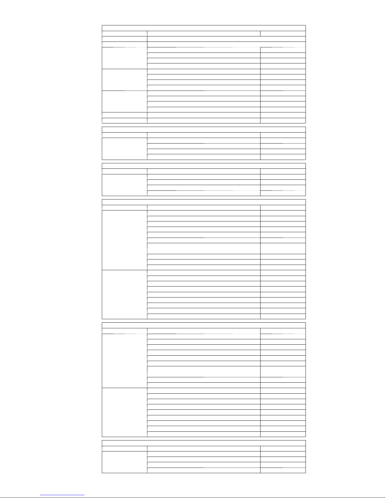
NOTE: Tables 2 through 6 show the piping size specifications.
Indoor Unit Piping Connection Sizes
Indoor High Wall
(DLFAHH)
Indoor High Wall
(DLFBHB)
Indoor Cassette
Indoor Ducted
Size 9 12 18
Pipe Connection Size - Liquid In. 1/4" 1/4" 1/4"
Pipe Connection Size - Suction In. 1/2" 1/2" 5/8"
Size 9 12 18 24
Pipe Connection Size - Liquid In. 1/4" 1/4" 1/4" 1/4"
Pipe Connection Size - Suction In. 1/2" 1/2" 5/8" 5/8"
Size 12 18 24
Pipe Connection Size - Liquid In. 1/4" 1/4" 3/8"
Pipe Connection Size - Suction In. 3/8" 1/2" 5/8"
Size 9 12 18 21 24
Pipe Connection Size - Liquid In. 1/4" 1/4" 1/4" 3/8" 3/8"
Pipe Connection Size - Suction In. 3/8" 3/8" 1/2" 5/8" 5/8"
Table 6—Indoor Floor Console
Size 9 12 18
Indoor Floor Console
Pipe Connection Size - Liquid In. 1/4" 1/4" 1/4"
Pipe Connection Size - Suction In. 3/8" 3/8" 1/2"
Refrigerant Piping:
Line sets to be sized based on the connection size of the indoor unit. Each pipe to be insulated individually.
Conversion Joints:
The outdoor unit may include a package of conversion joints to facilitate installation of various sizes of fan coils. These joints are to be
connected to the outdoor unit as needed to match the line set size.
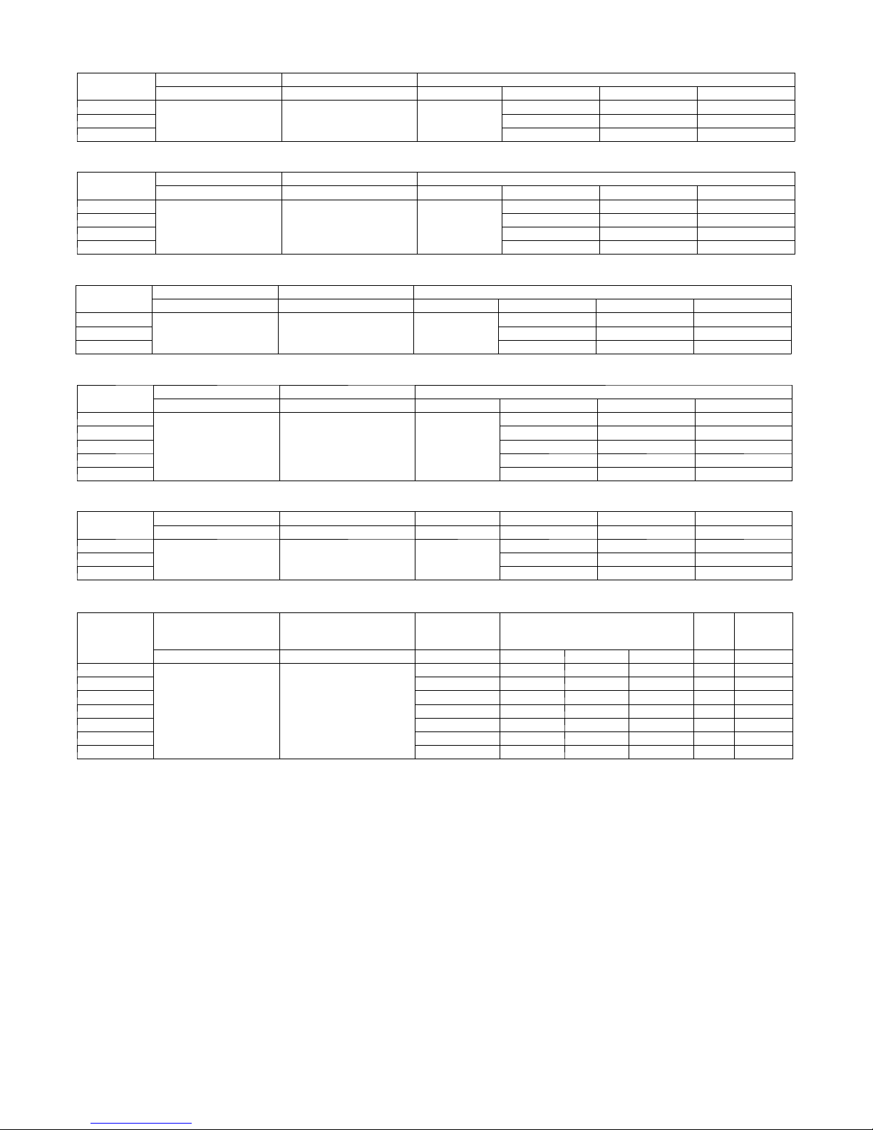
Table 7—Additional Refrigerant Charge
Total Line
Unit
Size
Length ft
Min Max
18 10 66
24 10 196 None None 0.20 / 0.20 0.20 / 0.20
30 10 230 None None None 0.24 / 0.58 0.24 / 0.58
36 10 246 None None None 0.24 / 0.58 0.24 / 0.58 0.24 / 0.58
42 10 246 None None None 0.24 / 0.58 0.24 / 0.58 0.24 / 0.58
48 10 443 None None 0.24 / 0.58 0.24 / 0.58 0.24 / 0.58 0.24 / 0.58 0.24 / 0.58
56 10 476 None None 0.24 / 0.58 0.24 / 0.58 0.24 / 0.58 0.24 / 0.58 0.24 / 0.58 0.24 / 0.58
10 - 32
(3 - 10)
None
>32 - 66
(10 - 20)
Additional Charge, 1/4” Liquid Line / 3/8” Liquid Line, oz/ft. ft (m)
>66 - 98
(20 - 30)
0.20 / 0.20
Outdoor Unit
Table 2—Indoor High Wall
Table 3—Indoor High Wall
Table 4—Indoor Cassette
Table 5—Indoor Ducted
>98 - 131.2
(30 - 40)
>131.2 - 196
(40 - 60)
>196 - 230
(60 - 70)
>230 - 246
(70 - 75)
>246 - 443
(75 - 135)
>443 - 476
(135 - 145)
Additional Refrigerant Calculation Sizes 30K, 36K and 42K:
Sum Total Liquid Pipe 1/4” (ft) x 0.24 + Sum Total Pipe 3/8” (ft) x 0.58 – 31 oz
Additional Refrigerant Calculation Sizes 48K and 56K:
Sum Total Liquid Pipe 1/4” (ft) x 0.24 + Sum Total Pipe 3/8” (ft) x 0.58 – 51.7 oz
NOTE: If the calculation results in a negative number no additional refrigerant is required.
NOTES:
EXV = Electronic Expansion Device
Electronic expansion valves in the outdoor unit are used as metering devices.
3
ELECTRICAL DATA
Table 8—High Wall DLFAHH
UNIT SIZE
9
12 0.1 0.0268 20
18 0.1 0.0268 20
UNIT SIZE
9
12 0.17 1/72 10
18 0.3 1/29 25
24 0.38 1/10 70
UNIT SIZE
12
18 0.18 1/72 46
24 0.43 1/20 46
UNIT SIZE
9
12 0.31 1/18 80
18 0.41 1/12 100
21 0.5 1/36' 124
24 0.5 1/36' 124
SYSTEM VOLTAGE OPERATINGVOLTAGE INDOORFAN
VOLT / PHASE / HZ MAX / MIN V-PH-HZ FLA HP W
0.1 0.0268 20
208-230/1/60 253 / 187 208-230/1/60
Table 9—High Wall DLFBHB
System Voltage OPERATING VOLTAGE INDOOR FAN
VOLT / PHASE / HZ MAX / MIN V-PH-HZ FLA HP W
0.17 1/72 10
208-230/1/60 253 / 187 208-230/1/60
Table 10—Cassette
System Voltage OPERATING VOLTAGE INDOORFAN
VOLT / PHASE / HZ MAX / MIN V-PH-HZ FLA HP W
0.18 1/72 46
208-230/1/60 253 / 187 208-230/1/60
Table 11—Ducted
System Voltage OPERATING VOLTAGE INDOORFAN
VOLT / PHASE / HZ MAX / MIN V-PH-HZ FLA HP W
0.28 1/24 80
208-230/1/60 253 / 187 208-230/1/60
Table 12—Floor Console
UNIT SIZE
9
12 0.14 1/24 30
18 0.14 1/24 30
System Voltage OPERATING VOLTAGE INDOOR FAN
VOLT / PHASE / HZ MAX / MIN V-PH-HZ FLA HP W
0.14 1/24 30
208-230/1/60 253 / 187 208-230/1/60
Table 13—Multi Zone Outdoor Unit
UNIT SIZE
18
24 11.5 0.59 1/8 90 21 35
30 13.9 0.68 1/6 150 19 30
36 15.6 0.82 2/9 240 21 35
42 17.8 0.82 2/9 240 24 40
48 23 1 1/6 150 30 50
56 23 1 1/6 150 30 50
*Permissible limits of the voltage range at which the unit will operate satisfactorily.
LEGEND
FLA - Full Load Amps
LRA - Locked Rotor Amps
MCA - Minimum Circuit Amps
RLA - Rated Load Amps
System Voltage OPERATING VOLTAGE COMPRESSOR OUTDOOR FAN MCA
VOLT / PHASE / HZ MAX / MIN RLA FLA HP W
7.2 0.62 1/12 60 15 25
208-230/1/60 253 / 187
MAX
FUSE/CB
AMP
4
!
EQUIPMENT DAMAGE HAZARD
Failure to follow this caution may result in equipment
damage or improper operation.
S Wires should be sized based on NEC and local codes.
S Use copper conductors only with a minimum 300 volt .
rating and 2/64 inch thick insulation.
!
EQUIPMENT DAMAGE HAZARD
Failure to follow this caution may result in equipment damage
or improper operation.
S Be sure to comply with local codes while running wire from
indoor unit to outdoor unit.
S Every wire must be connected firmly. Loose wiring may
cause terminal to overheat or result in unit malfunction. A
fire hazard may also exist. Therefore, be sure all wiring is
tightly connected.
S No wire should be allowed to touch refrigerant tubing,
compressor or any moving parts.
S Disconnecting means must be provided and shall be located
within sight and readily accessible from the air conditioner.
S Connecting cable with conduit shall be routed through hole
in the conduit panel.
All wires must be sized per NEC (National Electrical Code) or
CEC (Canadian Electrical Code) and local codes. Use Electrical
Data table MCA (minimum circuit amps) and MOCP (maximum
over current protection) to correctly size the wires and the
disconnect fuse or breakers respectively.
Per caution note, only copper conductors with a minimum 300
volt rating and 2/64- inch thick insulation must be used. The u se
of BX cable is not recommended.
18- 42
Sizes
Recomme nde d Connection Method for Power and
Communication - Wi r ing - Power and Communication Wiri ng:
The main power is supplied to the outdoor unit. The field supplied
14/3 power/communication wiring from the outdoor unit to indoor
unit consists of four (4) wires and provides the power for the
indoor unit. Two wires are high voltage AC power; one is
communication wiring and the other is a ground wire.
CAUTION
CAUTION
Recomme nde d Connection Method for Power and
Communication Wiring (To minimize communication wiring
interference)
Power Wiring:
The main power is supplied to the outdoor unit. The fie l d supplied
power wiring from the outdoor unit to indoor unit consists of three (3)
wires and provides the power for the indoor unit. Two wires are high
voltage AC powe r and one is a ground wi re. To mini mize voltage
drop, the fac tory recommended wir e size is 14/2 stranded with a
ground.
Communication Wiring:
A separate shielded copper conductor only, with a minimum 300
volt rating and 2/64- inch thick insulation, must be used as the
communication wire from the outdoor unit to the indoor unit.
Please use a separate shielded 16GA stranded control wire.
For sizes
Recomme nde d Connection Method for Power and
Communication - Wi r ing - Power and Communication Wiri ng:
Power Wiri ng OUTDOOR UNIT& BRANCH BOXES:
Separate power s upplies ar e required for t he outdoor unit and the
Branch Boxes. The indoor units are powered from the Branch Boxes.
The field supplied 14/3 power wiring from the OUTDOOR UNIT
consists of three (3) wires. Two wires are high voltage AC power, one
is a ground wire.
The field supplied 14/3 power wiring from the BRANCH BOXES
consists of three (3) wires. Two wires are high voltage AC power, one
is a ground wire.
Up to three (3) Branch Boxes can be powered from the same 15 amp
breaker.
Communication Wiring:
A separate shiel ded copper conductor only, with a minimum 300 volt
rating and 2/64- inch thick insulati on, must be used as the
communication wire from the OUTDOOR UNIT to the BRANCH
BOX.
Please use a separate shielded 16GA stranded control wire.
Power and Communication Wiring BRANCH BOXES to
INDOOR UNITS:
The field supplied 14/3 power/communication wiring from the
BRANCH BOX to the INDOOR UNIT consists of f our (4) wires
and provides the power for the indoor unit. Two wires are high
voltage AC power, one is communicat i on wiring “2” and the other is
a ground wire “N(1)”
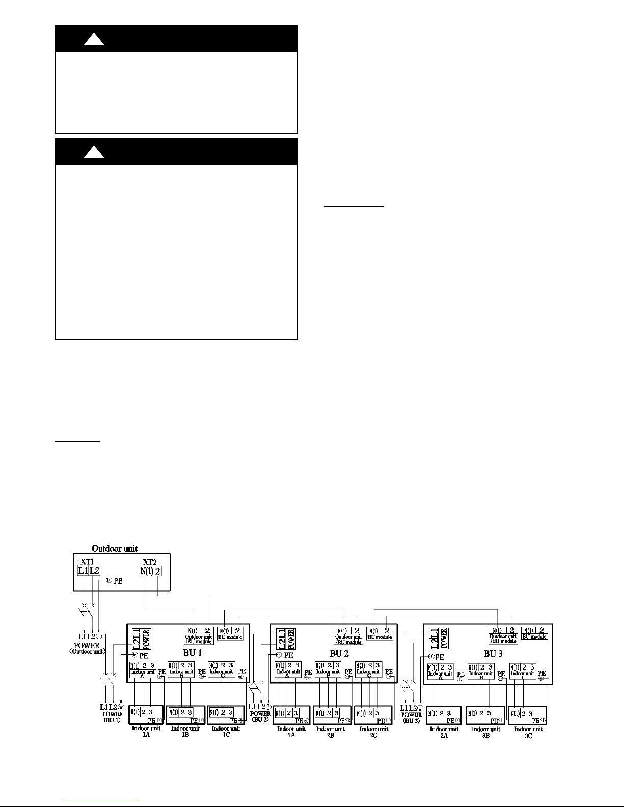
See diagr am below for detai ls on wiring for size s 48- 56.
48- 56
Fig. 1 - Wiring Connection
5
PARTS LIST
Size Name Qty
18 No parts included
24 No parts included
30
36
42
48 bellows φ16 1
56 bellows φ16 1
Size Name Qty
9,12,18
Size Name Qty
9,12,18,24
Size Name Qty
12,18
24
Size Name Qty
9,12,18
21,24
Size Name Qty
9,12,18
Outdoor Units
Conversion Joint 3/8 to 5/8 2
Conversion Joint 3/8 to 1/2 4
Conversion Joint 1/4 to 3/8 2
Screw M4X12 1
Conversion Joint 3/8 to 5/8 2
Conversion Joint 3/8 to 1/2 4
Conversion Joint 1/4 to 3/8 2
Screw M4X12 1
Conversion Joint 3/8 to 5/8 2
Conversion Joint 3/8 to 1/2 4
Conversion Joint 1/4 to 3/8 2
Screw M4X12 1
Indoor High Wall DLFAHH
Mounting Plate 1
Remote Control 1
Remote Control Holder 1
Battery (1.5V) 2
Indoor High Wall DLFBHB
Mounting Plate 1
Remote Control 1
Remote Control Holder 1
Battery (1.5V) 2
Indoor Cassette
Remote control 1
Battery (1.5V) 2
GasketM6Xφ18X1.4 4
GasketM10Xφ30X2.5 10
Screw ST4.8X13 HC 4
Screw M6X25 4
Nut of Connector Pipe(B)
Package
Pipe Connection Nut ("I" shape) 1
Connection wire of wired control 1
Wired controller 1
bellows φ16 1
Connection wire of wired control 1
Remote control 1
Battery (1.5V) 2
Gasket location board 1
Screw ST4.8X13 HC 4
Gasket 10 10
Nut of Connector Pipe(B) 1
Wired controller 1
Indoor Ducted
Remote control 1
Battery (1.5V) 2
Screw M10X8 4
Screw M10 4
Gasket 10GB93 4
Pipe Connection Nut ("I" shape) 1
Nut of Connector Pipe(B)
Package
Wired control 1
Connection wire of wired control 1
Remote control 1
Battery (1.5V) 2
Screw M10X8 4
Screw M10 4
Gasket 10GB93 4
Nut of Connector Pipe(B) 1
Wired controller 1
Connection wire of wired control 1
bellows φ16 1
Indoor Floor Console
Installation Panel 1
Remote Control 1
Remote Control Holder 1
Battery (1.5V) 2
1
1
6
DIMENSIONS - INDOOR
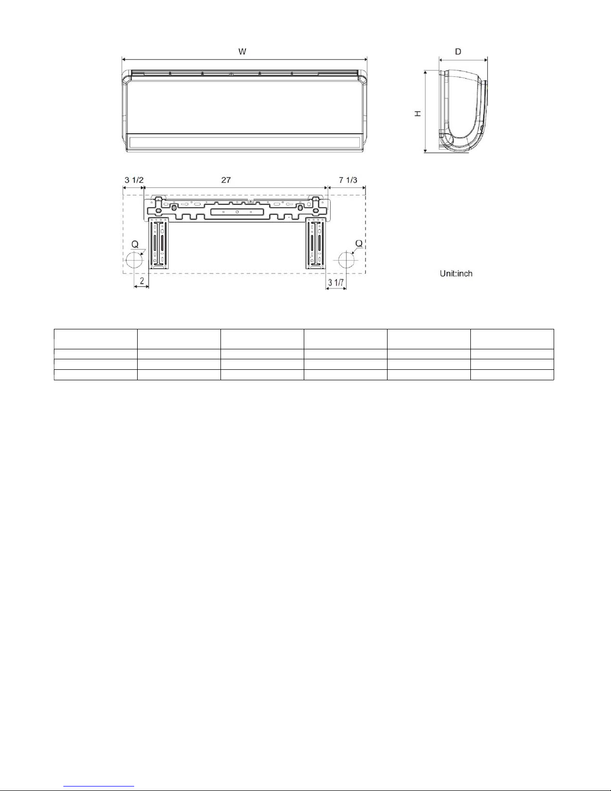
Fig. 2 - High Wall Dimensions
Table 14—High Wall DLFAHH Dimensions
Unit Size W In. (mm) D In. (mm) H In. (mm) Q In. (mm)
9k 37.8 (960)g 8.07 (205) 12.6 (320) 2.16 (55) 33.07 (15)
12k 37.8 (960) 8.07 (205) 12.6 (320) 2.16 (55) 33.07 (15)
18k 37.8 (960) 8.07 (205) 12.6 (320) 2.75 (70) 33.07 (15)
Operating Weight
Lbs. (kg)
7
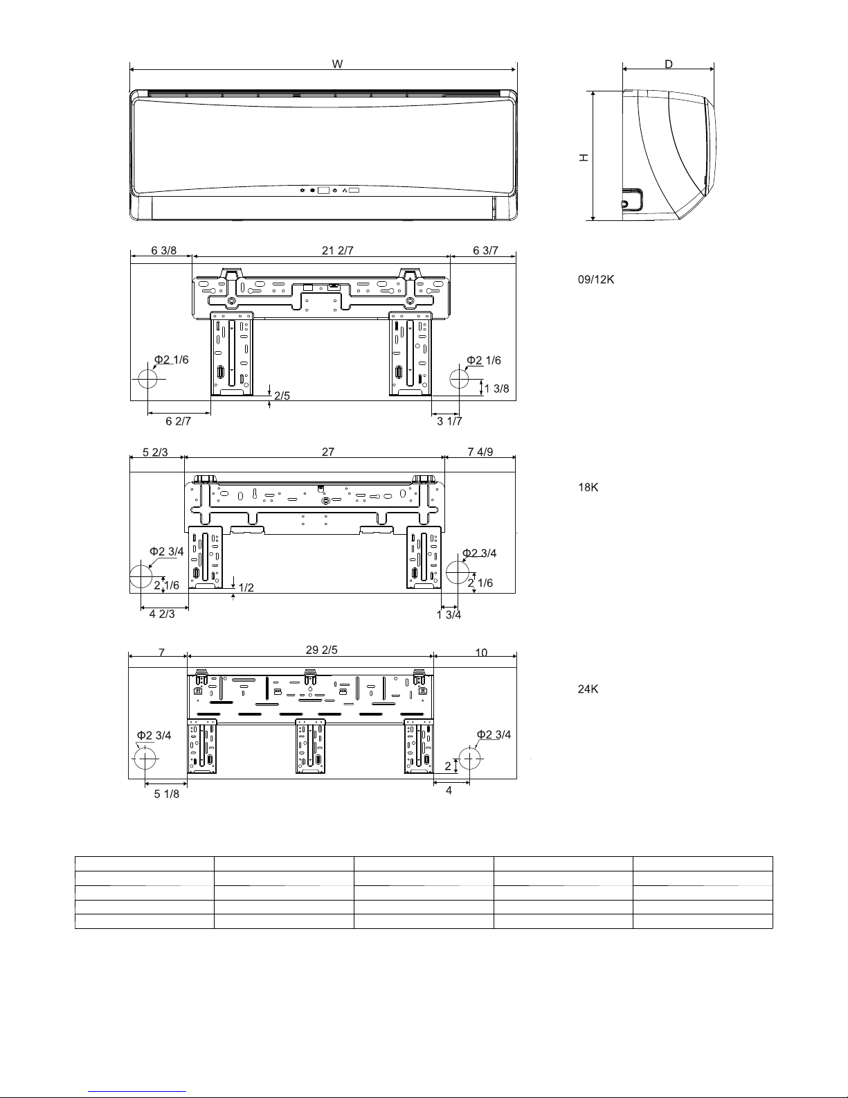
DIMENSIONS - INDOOR (CONTINUED)
Unit Size W In. (mm) D In (mm) H In. (mm) Operating Weight
9k 34.09 8.23 11.5 24.3
12k 34.09 8.23 11.5 24.3
18k 40.079 9.055 12.6 30.9
24 46.378 10.394 12.8 38.6
Fig. 3 - Wall Dimensions
Table 15—High Wall DLFBHB
8
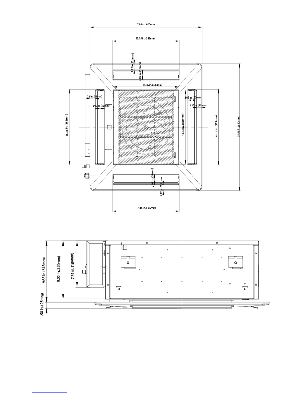
DIMENSIONS - INDOOR (CONTINUED)
Fig. 4 - Cassette Grill Dimensions
Fig. 5 - Cassette Side View Dimensions
9
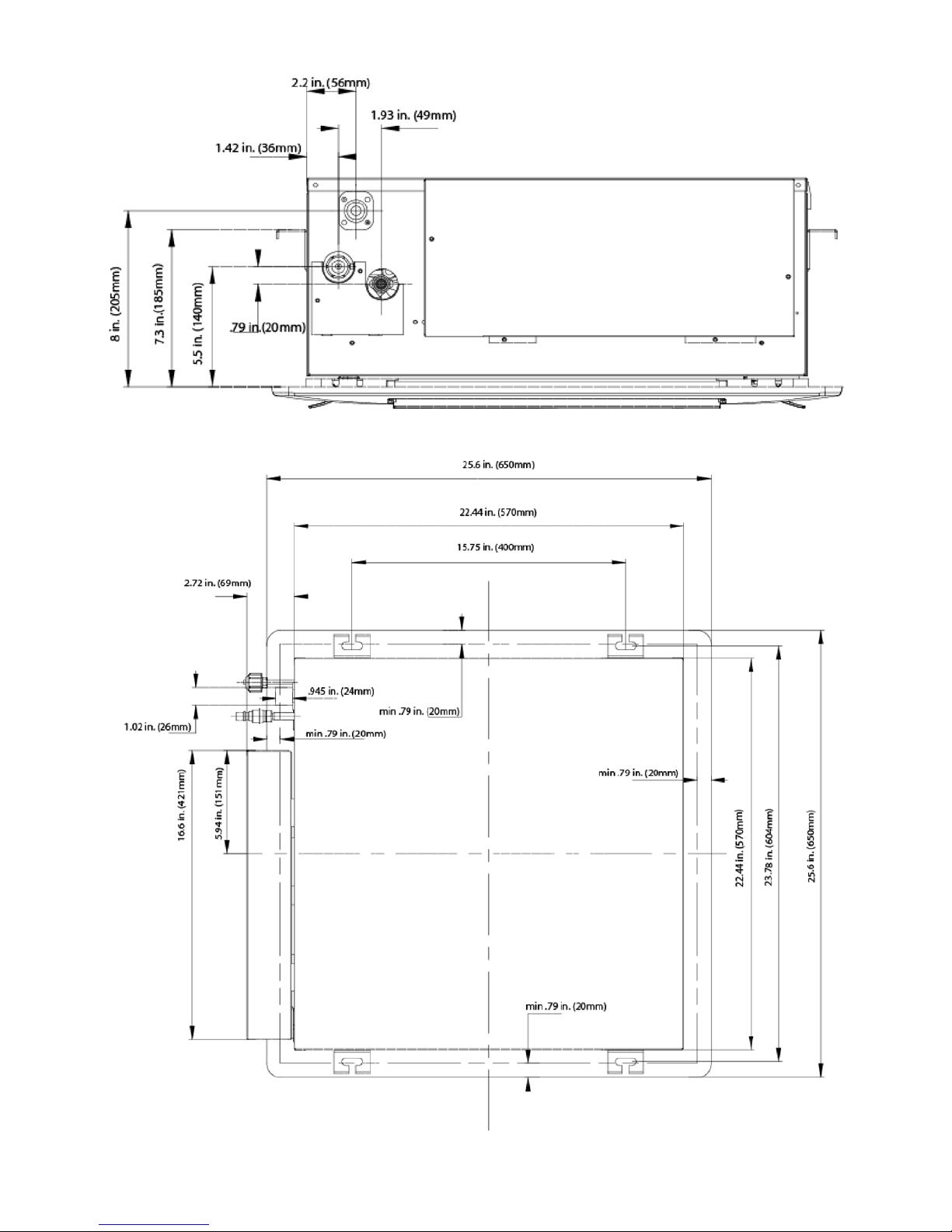
DIMENSIONS - INDOOR (CONTINUED)
Fig. 6 - Cassette Connection Side View Dimensions
Fig. 7 - Cassette Top View Dimensions
10
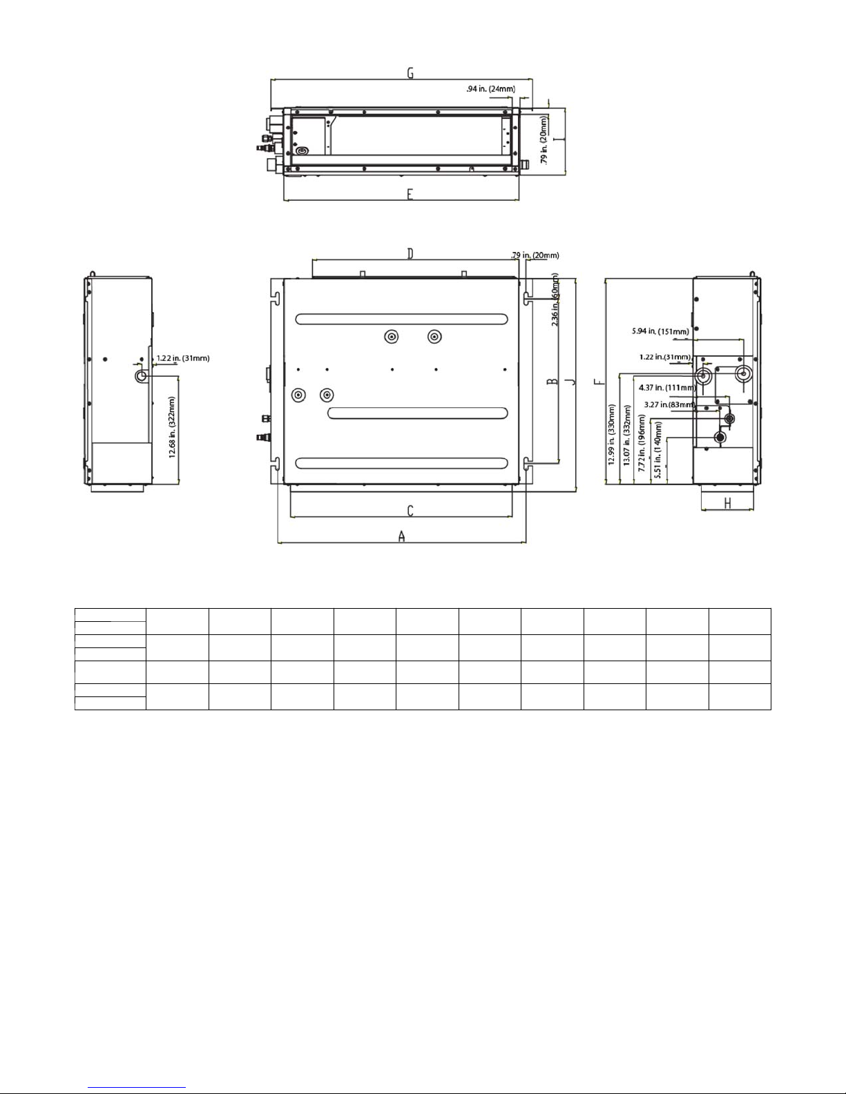
DIMENSIONS - INDOOR (CONTINUED)
Item
Size
09
12
18
21
24
Fig. 8 - Ducted Dimensions
Table 16—Outline Dimensions
A B C D E F G H I J
29 1/5 in
(742 mm)
37 in
(942 mm)
45 in
(1142 mm)
19 1/3 in
(491 mm)
19 1/3 in
(491 mm)
19 1/3 in
(491 mm)
26 in
(662 mm)
34 in
(862 mm)
41 4/5 in
(1062 mm)
24 2/5 in
(620 mm)
32 2/7 in
(820 mm)
40 1/6 in
(1020 mm)
27 5/9 in
(700 mm)
35 3/7 in
(900 mm)
43 1/3 in
(1100 mm)
24 1/5 in
(615 mm)
24 1/5 in
(615 mm)
24 1/5 in
(615 mm)
30 4/5 in
(782 mm)
38 2/3 in
(982 mm)
46 1/2 in
(1182 mm)
6 1/7 in
(156 mm)
6 1/7 in
(156 mm)
6 1/7 in
(156 mm)
7 7/8 in
(200 mm)
7 7/8 in
(200 mm)
7 7/8 in
(200 mm)
25 in
(635 mm)
25 in
(635 mm)
25 in
(635 mm)
11
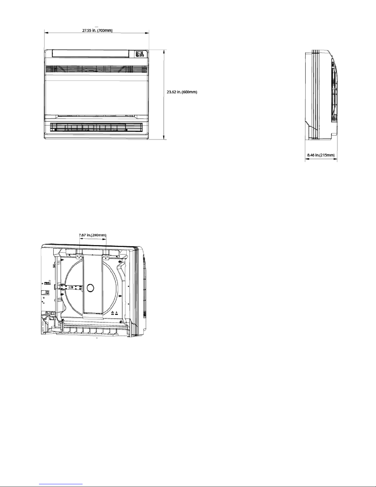
DIMENSIONS - INDOOR (CONTINUED)
Fig. 9 - Floor Console Dimensions
12
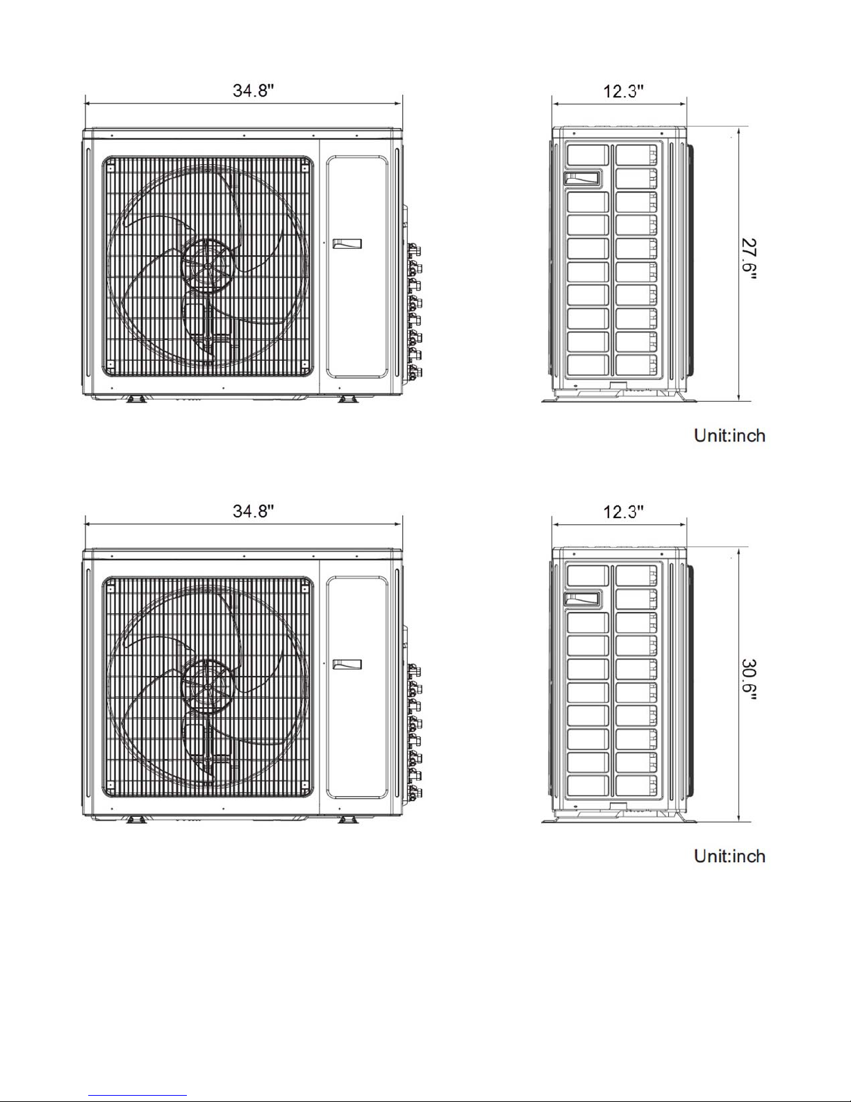
DIMENSIONS - OUTDOOR
Fig. 10 - Outdoor Dimensions Size 18
Fig. 11 - Outdoor Dimensions Size 24
13

DIMENSIONS - OUTDOOR (CONTINUED)
Fig. 12 - Outdoor Dimensions Size 30- 42
Fig. 13 - Outdoor Dimensions Size 48- 56
14

CLEARANCES - INDOOR
(0.13m)
min.
CEILING
6" (0.15m) min.
5
"
(1.8m)
6'
5
"
(0.13m)
min.
FLOOR
Fig. 14 - High Wall Clearance
Fig. 15 - Cassette Clearance
15

CLEARANCES - INDOOR (CONTINUED)
Fig. 16 - Ducted clearance
Fig. 17 - Floor console clearance
16

CLEARANCES - OUTDOOR (CONTINUED)
D
A
B
C
Air-outlet
Fig. 18 - Clearances Outdoor 18 - 42
Table 17—Clearances Outdoor
UNIT
A 24 (609)
B 24 (609)
C 24 (609)
D 4 (101)
E 4 (101)
Minimum Value
in. (mm)
Air-inlet
E
Fig. 19 - Clearances Outdoor 48- 56
17

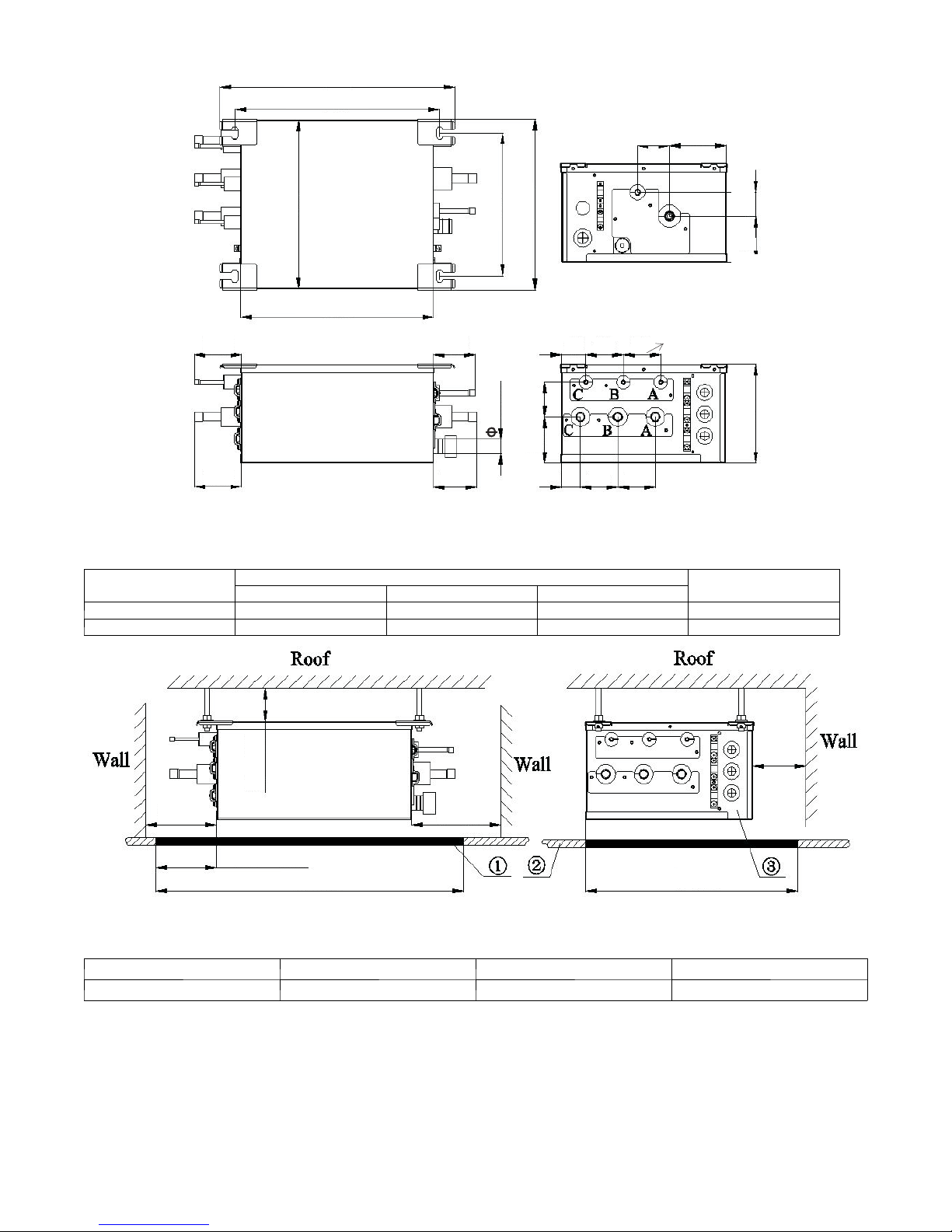
DIMENSIONS - BRANCH BOXES (REQUIRED ON SIZES 48 AND 56)
OUTLINE DIMENSION AND SERVICING SPACE OF KSAUI0201AAA
17 2/7 in (439 mm)
15 in (383 mm)
2 1/3 in (60 mm)
7 1/7 in (105 mm)
1 3/4 in (44 mm)
12 1/5 in (310 mm)
10 1/3 in (263 mm)
12 1/3 in (313 mm)
3 1/3 in (85 mm)
14 1/5 in (361 mm)
5 in (128 mm)
5 in (128 mm)
3 4/7 in (91 mm)
1 in (26 mm)
3 1/7 in (80 mm)
2 1/2 in (64 mm)
7 1/6 in (182 mm)
3 1/3 in (85 mm)
5 in (128 mm)
Sorts
Liquid Pipe
Gas Pipe
Port A Port B
5 1/5 in (132 mm)
Fig. 20 - Outline Dimensions
Table 18—Outline Dimensions
Indoor unit side (inch/mm)
2 2/5 in (61 mm)
3 1/2 in (88 mm)
Outdoor unit side (inch/mm)
17 5/7 in (450 mm)
≥
3/5 in (15 mm)~4/5 in (20 mm)
4 in (100 mm)~4 5/7 in (120 mm)
23 5/8 in (600 mm)
≥
No.
Name Service space Ceiling Electrical box side
17 5/7 in (450 mm)
≥
23 5/8 in (600 mm)
≥
Fig. 21 - Installation and Service Space
Table 19—Installation and Service Space
1 2 3
18
11 4/5 in (300 mm)
≥
OUTLINE DIMENSION AND SERVICING SPACE OF KSAUI0401AAA
17 2/7 in (439 mm)
15 in (383 mm)
2 1/3 in (60 mm)
7 1/7 in (105 mm)
1 3/4 in (44 mm)
12 1/5 in (310 mm)
10 1/3 in (263 mm)
12 1/3 in (313 mm)
3 1/3 in (85 mm)
14 1/5 in (361 mm)
5 in (128 mm)
5 in (128 mm)
1 4/5 in (35 mm)
2 3/4 in (70 mm)
2 3/4 in (70 mm)
2 1/2 in (64 mm)
1 in (26 mm)
7 1/6 in (182 mm)
3 1/3 in (85 mm)
5 in (128 mm)
Sorts
Liquid pipe
Gas liquid
Port A Port B Port C
5 1/5 in (132 mm)
Fig. 22 - Outline Dimensions
Table 20—Outline Dimensions
Indoor unit side (inch/mm)
1 3/8 in (35 mm)
2 3/4 in (70 mm)
2 3/4 in (70 mm)
Outdoor unit side (inch/
mm)
11 4/5 in (300 mm)
≥
19 2/3 in (500 mm)
≥
3/5 in (15 mm)~4/5 in (20 mm)
17 5/7 in (450 mm)
≥
4 in (100 mm)~4 5/7 in (120 mm)
23 5/8 in (600 mm)
≥
Fig. 23 - Installation and Service Space
Table 21—Installation and Service Space
No.
Name Servicing Space Ceiling Electrical box side
1 2 3
19
23 5/8 in (600 mm)
≥

INSTALLATION GUIDE
3
Up to nine fan coil units can be connected to one outdoor unit.
Refer to the Product Data for approved combinations.
Ideal installation locations include:
Each Indoor
Unit
S A location where there are no obstacles near inlet and outlet area.
S A location which can bear the weight of indoor unit.
S Do not install indoor units near a direct source of heat such as
direct sunlight or a heating appliance.
S A location with the appropriate clearances (see Fig. 14).
Outdoor
Unit
S A convenient location for the instal l ation that is not exposed to
strong wind. If unit is exposed to strong winds it is recomm ended
that a field- fabricated wind baffle be used (see Fig. 73).
S A location which can bear the weight of outdoor unit and where
the outdoor unit can be mounted in a level position.
S A location which provides appropriate clearances (see Fig. 17
and Fig. 18).
S Do not install the indoor or outdoor units in a location with
special environmental conditions. For those applications, contact
your Sales Representative.
HIGH- WALL INDOOR UNIT
INSTALLATION
INSTALL MOUNTING PLATE
For each fan coil:
1. Carefully remove the mounting plate, which is attached to
the back of the indoor unit.
2. The mounting plate should be located horizontally and level
on the wall.
3. If the wall is block, brick, concrete or similar material, drill .2”
(5 mm) diamete r holes and insert anchors for t he appropriat e
mounting screws.
4. Attach the mounting plate to the wall (see Fig. 2 and 3).
FOR EACH F AN COIL, DRILL HOLE IN WALL FOR
INTERCONNECTING PIPING, DRAIN AND WIRING
Refrigerant Line Routing
The refrigerant lines may be routed in any of the four directions
showninFig.24(a)and(b).
For maximum serviceability, it is recommended to have refrigerant
line flare connections and the drain connection on the outside of
the wall that the fan coil is mounted on.
If piping is going through the back:
1. Determine pipe hole position using the mounting plate as a
template. Drill pipe hole diameter per chart below. The
outside pipe hole is 1/2- in. (13 mm) min. lower than inside
pipe hole, so it slants slightly downward (see Fig. 25).
If piping is going to exit from the left rear, it is
recommended to field-fabricate piping extensions to get the
flare connections to the outside of the wall.
1/2 in. (13 mm)
Min.
INDOOR
OUTDOOR
Fig. 25 - Drill Holes
Table 22—Hole Diameter
Unit Size
9k, 12k, 18k and 24k 3.75 (95)
Hole Diameter
in. (mm)
If piping is going through the right or left side:
1. Use a small saw blade to carefully remove the
corresponding plastic covering on side panel and drill the
appropriate size hole where the pipe is going through the
wall (see Fig. 24 (c)).
2. Remove knockout 1 if you are running only the wiring.
Remove knockout 1 and 2 or knockout 1, 2 and 3 if you are
running both piping and wiring through the side of the unit.
!
CAUTION
DLFAHH Rear left condensate drain connection on
unit.
When piping out of the rear right, a field supplied joint
connection will need to be made behind the unit.
Please ensure that the connection is made properly to avoid
leaks.
A07371
As viewed from front
Left Exit
1
Right Exit
2
( a )
Right Rear Exit
( b )
3
Left Rear Exit
4
Fig. 24 - Refrigerant Line Routing
Knockout
Knockout 2
Knockout 1
( c )
A08281
20

DUCTED INDOOR UNITS INSTALLATION
A
INSTALLATION OF THE INDOOR DUCTED UNIT
Requirements on the Installation Location
1. Ensure the hanger is strong enough to withstand the weight
of the unit.
2. The drainage pipe is easy for connection.
3. No obstacle is in the inlet/outlet and the air circulation is in
good condition.
4. Ensure the installation space is left for access to
maintenance.
5. It should be far away from where there is a heat source,
leakage of any inflammable, explosive substances, or smog.
6. It is the ceiling type unit (concealed in the ceiling).
7. The power cords and connection lines of the indoor and
outdoor units must be at least 1m away from the TV set or
radio to avoid the image interference and noise (even if 1m
is kept, the noise may be produced due to the strong
electromagnetic wave).
Installation of the Indoor Ducted
1. Insert the M10 expansion bolt into the hole, and then knock
the nail into the bolt. Refer to the Outline Dimension
Drawings of the Indoor Unit for the distance between holes
and see Fig.26 for the installation of the expansion bolt.
Unit
!
CAUTION
S Prior to the inst allation, make a good preparation for all piping
(refrigerant pipe, drain pipe) and wiring (wires of the wired
controller, wires between the indoor and outdoor unit) of the
indoor unit to make the further installation much easi er.
S If there is an opening in the ceiling, its better to reinforce it
to keep it flat and prevent it from vibrating. Consult the user
and builder for more details.
S If the strength of the ceiling is not strong enough, a bea m
made of angle iron can be used and then sec ur e the unit on it.
S If the indoor unit is not installed in the air conditioning
area, please use sponge around the unit to prevent
condensing. The thickness of the sponge depends on the
actual installation environment.
HORIZONTAL CHECK OF THE INDOOR DUCTED
UNIT
After the installation of the indoor unit, its horizontality must be
checked to make sure the unit keeps a horizontal fore and aft and
maintains an inclination of 5
as shown in Fig.29.
_ toward the drain pipe right and left,
Fig. 26 - Expansion Bolt
2. Install the hanger on the indoor unit (see Fig.27).
Hanger bolt
nchor
Air conditioning unit
Fig. 27 - Hanger Bolt
3. Install the indoor unit on the ceiling, as shown in Fig.28.
48mm
Fig. 28 - Install the indoor unit
Horizontality Check Device
Fig. 29 - Horizontal check device
INSTALLATION OF THE AIR SUPPLY DUCT
1. Installation of the Rectangular Air Supply Duct
1
2
3
Return air
4 6 83 75
Fig. 30 - Installation of Air Duct Supply
No. Name No. Name
1 Hanger 5 Plenum Box
2 Return Air Duct 6 Filter Screen
3 Canvas Duct 7
4 Return Air Heat 8
Return air
Table 23—Air Duct
Supply air
Main Air
Supply Duct
Air Supply
Outlet
21

INSTALL THE ROUND AIR SUPPL Y DUCT
D
1
2
4
5 6 7
3
8 9
Fig. 31 - Air supply duct
Table 24—Air Duct
No. Name No. Name
1 Return Air Duct 6 Transition Duct
2 Canvas Duct 7 Air Supply Duct
3
4 Hanger 9 Diffuser Joint
5 Air Supply Duct
Return Air
Louver
8 Diffuser
INSTALLATION STEPS OF THE ROUND AIR
SUPPLY DUCT
1. Pre- install the outlet of the round duct on the transition duct
and then secure it with the tapping screw.
2. Place the transition duct to the air outlet of the unit and
secure it with a rivet.
3. Connect the outlet to the duct and then tighten them with
tape. Other installation details are not covered herein.
C
Fig. 33 - Return Air Inlet
Table 25—Dimensions of the Air Supply Outlet and Return
Air Inlet (unit: in/mm)
Item Air Supply Outlet Return Air Inlet
Size A B C D
09
12
18
21
24
6 1/7 in
(156 mm)
6 1/7 in
(156 mm)
6 1/7 in
(156 mm)
26 in (662
mm)
34 in (862
mm)
41 4/5 in
(1062
mm)
22 5/6 in
(580 mm)
30 5/7 in
(780 mm)
38 4/7 in
(980 mm)
22 5/6 in
(580 mm)
6 3/8 in
(162 mm)
6 3/8 in
(162 mm)
INSTALLATION OF THE RETURN AIR DUCT
1. The default installation location of the rectangular flange is
in the back and the return air cover plate in in the bottom as
shown in Fig.34.
Rectangular Flange
Backward Return Air
Downward Return Air
!
CAUTION
S The max. lengt h of the duct means the max. length of the air
supply duct plus the max. length of the ret urn air duct.
S The duct is either rectangular or round and connected with
the air inlet/outlet of the indoor unit. Among all air supply
outlets, at least one should remain open. As for the round
duct, it needs a transition duct of which the size should
match with the air supply of the unit. After the fitting of the
transition duct, it is best to keep the round duct 32ft (10m)
away from the corresponding diffuser.
DRAWINGS OF THE AIR SUPPLY OUTLET AND
RETURN AIR INLET
21
A
B
Fig. 32 - Air Supply Outlet
Return Air Cover Plate
Fig. 34 - Return Air Duct
2. If the downward return air is desired, just change the place
of the rectangular flange and the return air cover plate.
3. Connect one end of the return air duct to the return air outlet
of the unit by rivets and the other to the return air louver.
For the sake of the convenience to freely adjust the height, a
cutting of canvas duct will be helpful, which can be
reinforcedandfoldedby8#ironwire.
4. More noise is likely to be produced in the downward return
air mode than the backward return air mode. We suggest
installing a muffler and a plenum box to minimize the noise.
5. The instal l ation me t hod can be c hosen with consideri ng the
conditions of the building and maintenance etc. (see Fig. 35).
64
5
Wind supply
Back wind
Install the back wind pipe (a)
4
2
Wind supply
1
5
Install the back wind pipe(b)
Fig. 35 - Return Air Duct
Table 26—Air Duct
No. Name No. Name
1 Return Air Louver
(with the filter screen)
2 Canvas Duct 5 Air Supply Duct
3 Return Air Duct 6 Access Grille
4 Indoor Unit
3
1
Back wind
22

INSTALLATION OF THE CONDENSATE PIPE
1. The condensate pipe should keep a inclination angle of 5 ~
10”, to facilitate the drainage of the condensate water. And
the joints of the condensate pipe should be insulated by the
insulation material to prevent condensing (see Fig. 36).
Insulating Layer for the Condensate Pipe
5. Insert the drain hose into the drain hole and tighten it with
clamps.
6. Wrap the clamps with large amount of sponge for thermal
insulation.
7. The drain hose inside the room also should be insulated.
Clamp (accessory)
Sponge (accessory)
Clamp
(accessory)
Pipe Lid
Fig. 36 - Thermal Insulation of the Condensate Pipe
2. There is a condens ate outlet on both the left and right sides of
the unit. Once one i s confirmed for use, the other should be
clogged by a rubber plug, bundle d by the binding wire and
insulated by the insulation material to avoid water leakage.
3. The right outlet is defaulted to be clogged with a plug.
IMPORTANT: No water leakage is allowed on the joint of the
condensate pipe.
DESIGN OF THE DRAIN PIPE
1. The drain pipe should always be kept an inclination angle
(1/50~1/100) to avoid water from gathering.
2. During the connection of the drain pipe and devi ce, do not
impose excessive forc e on the pipe on one side of the device.
Additionally the pipe should be secured closely to the device.
3. The drain pipe can be the ordinary hard PVC pipe which
can be purchased locally. During the connection, inset the
end of the PVC pipe to the drain outlet, then tighten it with
the drain hose and binding wire. Never connect the drain
outlet and the drain hose with adhesive.
4. When the drain pipe is used for multiple devices, the public
section of the pipe should be 4 in (100 mm) lower than the
drain hole of each device and it is better to use the much
thicker pipe for such a purpose.
INSTALLATION OF THE DRAIN PIPE
1. The diameter of the drain pipe should be larger than or
equal to that of the refrigerant pipe (PVC pipe, outer
dimater: 1 in (25 mm), wall thickness
2. The drain pipe should be a short as possible and with at
least a 1/100 degree of slope to avoid forming air pockets.
3. If the proper degree of slope of the drain pipe is not
allowed, a lift pipe should be installed.
4. A distance of 3.28 ft~4.92 ft (1m~1.5 m) should be kept
betwe en the hangers to avoid the drain hose from making a
turn.
0.06 in (1.5 mm).
Sponge (gray) Drain Hose
Max. 4mm
Fig. 38 - Drain Hose Insulation
PRECAUTIONS FOR THE LIFT PIPE
The lift pipe install height should be less than 33 1/2 in (850 mm). We
recommend setting an inclination angle 1~ 2
the drainage direction. If the lift pipe and the unit form a right angle,
the height of the lift pipe must be less than 31 1/2 in (800 mm).
1~1.5m
Lift Pipe
850mm
1000mm
150mm
Drain Hose (accessory)
Hanger Bracket
11 4/5 in (300 mm)
Clamp (accessory)
1° 2°
Fig. 39 - Installation Height
NOTE:
1. The inclination height of the drain hose should be within 3
in. (75 mm) so that the outlet of the drain hose does not
suffer any external force.
2. If multiple drain pipes converge, follow the installation
steps below.
The specification of the joint of the drain pipe should be suitable to the running capacity of the unit
Drain Hose (accessory)
Max.75mm
Max.1000mm
_ for the lift pipe toward
Ceiling
3.28 ft~4.92 ft
(1m~1.5 m)
(Wrong)
Fig. 37 - Slope Degree
Fig. 40 - Multiple Line Convergence
23

FLOOR CONSOLE INDOOR UNITS
INSTALLATION
Follow these key steps when selecting a location for the unit.
S Select a placewhere cool air can be distributed throughout
the room.
S Select a place where condensation water is easily drained
away.
S Select a site that can handle the weight of the indoor unit.
S Select a place which has easy access for maintenance.
Indoor unit
The indoor unit should be sited in a place where:
1. The restrictions for the installation specified in the indoor
unit installation drawings are met.
2. Both the air intake and exhaust have clear paths.
3. The unit is not in the path of direct sunlight.
4. The unit is away from a heat or steam source.
5. There is no source of machine oil vapour (this may shorten
indoor unit life).
6. Cool (warm) air is circulated throughout the room.
7. The unit is away from electronic ignition type fluorescent
lamps (inverter or rapid stert type) as they may shorten the
remote controller range.
8. The unit is at least 3.28 ft (1 m) away from any television or
radio set (unit may cause interference with the picture or
sound).
CAUTIONS FOR INSTALLATION WHERE AIR
CONDITIONER TROUBLE IS LIABLE TO OCCUR
S Do not install in areas with or near an abundance of oil.
S Do not install in areas with an acid base area.
S Do not install in areas with an irregular electrical supply.
Mounting plate
Drawings
Half conceated
Concealed
Grid(field supply)
Indoor Unit Installation
The indoor unit may be mounted in any of the three styles shown
here.
Exposed
Molding
Floor lnstallation Wall Installation
Fig. 41 - Indoor Unit Installation Drawings
Location for securing the installation
7 7/8 in (200
4 5/7 in (120 mm
)
8 2/3 in (220 mm)
6 2/3 in (170 mm)
1 1/6 in (30 mm)
25 1/3 in (644 mm)
panel
27 5/9 in (700 m
mm)
1 1/6 in (30 m
m)
m)
)
m
m
021(
n
i
7
/
5
4
(570 mm)
)m
n
m
0
2
2(
23 5/8 in (600 mm)
22 4/9 i
n
i
3/
2 8
6 2/7 in (160 mm
Schematic drawing of hooks:
7 7/8 in (200 mm)
Fig. 42 - Schematic Drawing of Hooks
INSTALLATION
PAPER PLANK
Fig. 43 - Installation Paper Plank
REFRIGERANT PIPING
Use the following steps to connect the refrigerant pipe.
1. Drill a hole (2 1/6 in (55 mm) in diameter ) in the spot
indicated by the
2. The location of the hole is different depending on which
side of the pipe is taken out.
3. For piping, see Connecting the refrigerant pipe, under
Indoor Unit Installation (1).
4. Allow space around the pipe for a easier indoor unit pipe
connection.
symbol in the illustration as below.
(Unit : in/mm)
Wall
)
Left bottom piping
24
1 7/9 in (45 mm)
3 in (75 mm)
2 1/3 in (60 mm)
Right bottom piping
3 in (75 mm)
Fig. 44 - Piping

Left back piping Right back piping
3 in (75 mm)
1 7/9 in (45 mm)
3 in (75 mm)
1 7/9 in (45 mm)
Left/right piping
1 7/9 in (45 mm)
Fig. 45 - Back piping
!
CAUTION
The suggested shortest pipe length is 8.2 ft (2.5 m) to avoid
noise from the outdoor unit and vibration. (Mechanical
noise and vibration may occur depending on how the unit is
installed and the environment in which it is used.)
See the installation manual for the outdoor unit for the
maximum pipe length.
1 7/9 in (45 mm)
DRILLING A WALL HOLE AND INSTALLING
WALL EMBEDDED PIPE
S For walls containing metal frameormetal board ,be sureto
use a wall embedded pipe and wall cover in the
feed-through hole to prevent water leakage.
S Be sure to caulk the gaps around the pipes with caulking
material to prevent water leakage.
1. Bore a feed- through hole of 2 1/6 in (55 mm) in the wall so
it has a down slope toward the outside.
2. Insert a wall pipe into the hole.
3. Insert a wall cover into wall pipe.
Inside Outside
Wall embedded pipe
(field supply)
Wall hole cover
Caulking
2 1/6 in (55 mm)
Refrigerant pipe
Fig. 46 - Refrigerant Pipe
3 in (75 mm)
Fig. 47 - Refrigerant Pipe
wall
Floor
13 7/9 in (350 mm)
1 7/9 in (45 mm)
Wall embedded pipe
(field supply)
Fig. 48 - Wall Embedded Pipe
4. After completing refrigerant piping, wiring, and drain
piping, caulk pipe hole gap with putty.
DRAIN PIPING
1. Use commercial regid polyvinyl chloride pipe general VP
20 pipe, outer diameter 1 in (26 mm), inner diameter 4/5 in
(20 mm) for the drain pipe.
2. The drain hose (outer diameter 5/7 in (18 mm) at
connecting end, 8 2/3 in (220 mm) long)is supplied with the
indoor unit. Prepare the drain pipe picture below position.
3. The drain pipe should be inclined downward so that water
will flow smoothly without any accumulation. (Should not
beatrap.)
4. Insert the drain hose to this depth so it will not be pulled out
of the drain pipe.
5. Insulate the indoor drain pipe with 10mm or more of
insulation material to prevent condensation.
6. Remove the air filters and pour some water into the drain
pan to check the water flows smoothly.
6 in (150 mm)
Must be no trap
25
4 in (100 mm)
4 in (100 mm)
Drain hose
Reducer
Fig. 49 - Trap
2 in (50 mm)
or more
Vinyl chloride
drain pipe
Do not touch water
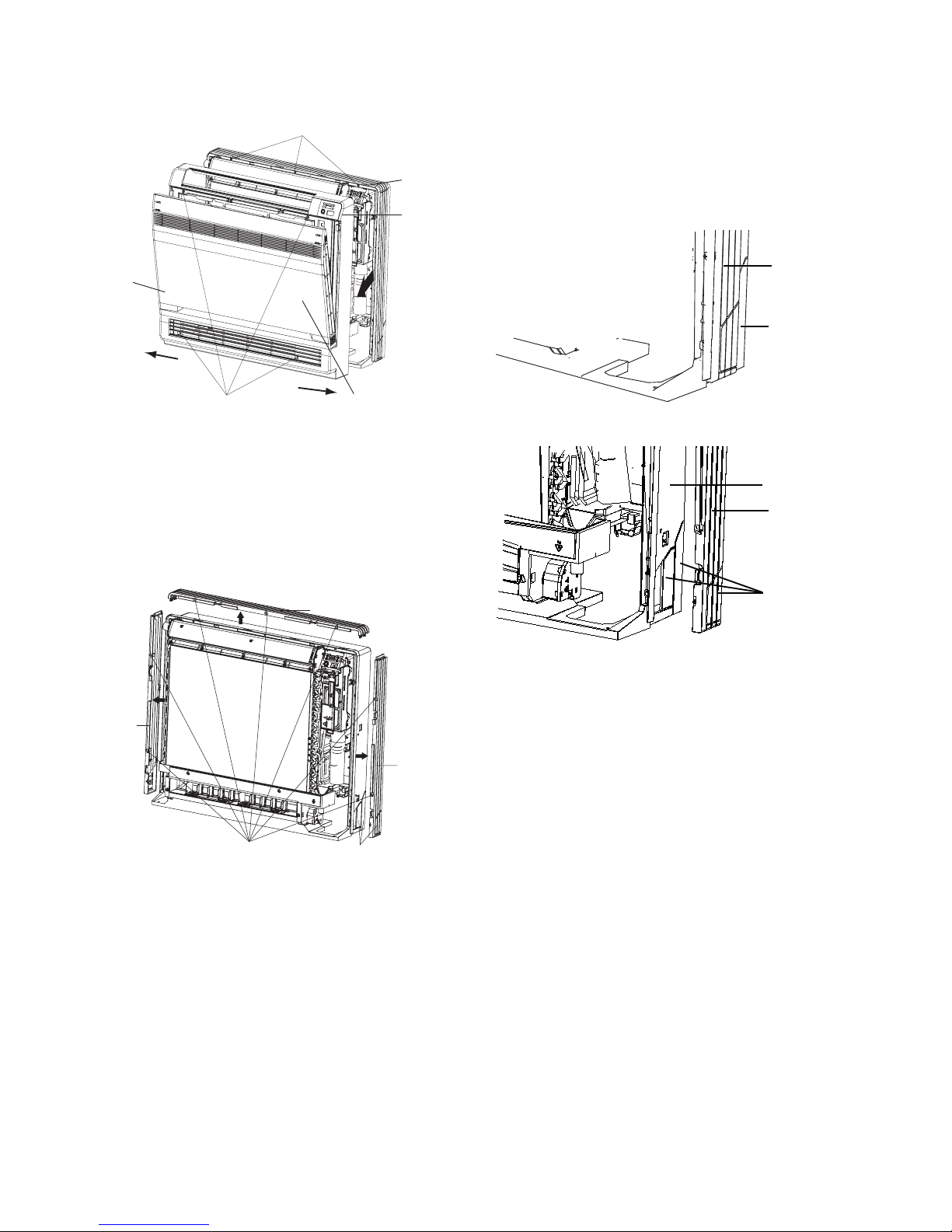
INSTALLING THE INDOOR UNIT
1. Preparation
S Open the front panel, remove the 4 screws and dismount
the front grille while pulling it forward.
3 tabs
Casing
Front
grille
For Side Piping
S Remove the pillars.
(1.) Remove the 7 screws.
(2.) Remove the upper casing (2 tabs).
(3.) Remove the left and right casings (2 tabs on each
side).
(4.) Remove the slit portions on the bottom frame and
casings using nippers.
(5.) Return by following the steps in reverse order
(3>2>1).
Front panel
Remove 4 screws
Open the front panel
Fig. 50 - Remove the screws
S Follow the arrows to disengagetheclasps on the front case
to remove it.
S Follow the procedure below when removing the slit
portions.
For Moldings
S Remove the pillars. Remove the slit portions on the bottom
frame using nippers.
2)Upper casing
3)Side
casings
Remove
front grille
3)Side
casings
Casing
Remove the pillar
Fig. 52 - Remove the pillar
Bottom frame
Casing
Remove the pillar
Fig. 53 - Remove the pillar
2. Installation
S Secure using 6 screws for floor installations. Do not forget
to secure to the rear wall.
S For wall installations, secure the mounting plate using 5
screws and the indoor unit using 4 screws.
Remove 7 screws
Fig. 51 - Remove the screws
Remove the pillar
26

The mounting plate should be installed on a wall which can
support the weight of the indoor unit.
(1.) Temporarily secure the mounting plate to the wall,
make sure that the panel is completely level, and
mark the boring points on the wall.
(2.) Secure the mounting plate to the wall with screws.
Casing
6screws
Fig. 54 - Floor Installation
7 7/8 in (200 mm)
Molding
6screws
Fig. 55 - Wall Installation
(3.) Once refrigerant piping and drain piping
connections are complete, fill in the gap of the
through hole with putty. A gap can lead to
condensation on the refrigerant pipe, and drain
pipe, and the entry of insects into the pipes.
(4.) Attach the front panel and front grille in their
original positions once all connections are
complete.
Flaring the Pipe
End
1. Cut the pipe end with a pipe cutter.
2. Remove burrs with the cut surface facing downward so that
the chips do not enter the pipe.
3. Fit the flare nut on the pipe.
4. Flare the pipe.
5. Check that the flaring is properly made.
Set exactly at the position shown below
Flare tool for R410A
Cut exactly
at right
angles
Renove
burrs
A
Die
Clutch-type
A
0~0.02 in (0~0.5 mm)
Flaring
Conventional flare tool
Clutch-type
(Rigid-type)
0.04~0.06 in
(1.0~1.5 mm)
Fig. 56 - Flaring
!
WARNING
(1.) DO not use mineral oil on flared part.
(2.) Prevent mineral oil from getting into the
system as this would reduce the lifetime of
the units.
(3.) Never use piping which had been used for
previous installations. Only use parts which
are delivered with the unit.
(4.) Do never install a drier to this R410A unit
in order to guarantee its lifetime.
(5.) The drying material may dissolve and
damage the system.
(6.) Incomplete flaring may cause refrigerant gas
leakage.
Flare’s inner
surface must
be scratch-free
Wing-nut type
(lmperial-type)
0.06~0.08 in
(1.5~2.0 mm)
The pipe end must
be evenly flared in
a perfect circle
Make sure that the
flare nut is fitted
27

CASSETTE TYPE INDOOR UNIT INSTALLATION
37 2/5 in ( 950 mm)
37 2/ 5 in (950 m m)
35 in(8 90 mm )
35 in(8
9
0
m
m
)
33 in(8 40 mm )
33 in(8 40 mm)
3
0 5
/
7 in (780
m
m
)
26 7/9 in (680 m m)
4/5 i n
59 in
(1500 mm)
(20 m m)
59 in
(1500 mm)
70 6/ 7
in/mm
in (1800 mm)
Fig. 57 - Schematic diagram of installation spaces
Select install location of the indoor unit
1. Obstructions should be removed from the indoor unit’s
intake or outlet vents so the air can flow throughout the
room.
2. Make sure the installation is in accordance with the
requirements of the required clearances on the schematic
diagram.
3. Select a location that can withstand 4 times the weight of
the indoor unit and would not increase the operating noise.
4. Ensure the unit is level.
5. Select a location where condensated coagulated water can
drain easy connect easy with the outdoor unit.
6. Ensure there is enough space for care and maintenance.
Ensure the weight between the indoor unit and ground is
above 70 6/7 in (1800 mm).
7. When installing the steeve bolt, check if the install place can
withstand a weight 4 times of the unit’s. If not, reinforce
before installation. Refer to the install cardboard and find
where the location should be reinforced.
NOTE: There will be lots of lampblack and dust stick on the
acentric, heat exchanger and water pump in the dining room and
kitchen, which would reduce the capacity of heat exchanger, lead
water leakage and abnormal operation of the water pump. The
following treatment should be taken under this circumstance:
(1.) Ensure the smoke trap above the cooker has
enough capacity to obviate lampblack to prevent
the indraft of the lampblack by the air conditioner.
(2.) Keep the air conditioner far from the kitchen so that
the lampblack does not indraft into the air
conditioner.
IMPORTANT: To guarantee the good performance, the unit must
be installed by professional personnel according with this
instruction.
12
18
24
25 3/5 in (650 mm)
22 4/9 in (570 mm)
15 3/4 in (400 mm)
Install dimension of mode
10 1/4 in
(260 mm)
)mm 075( n
)
mm
406(
n
i
i
9/
9/7
4
22
32
)mm
05
6( ni
5/
3 5
2
Fig. 58 - Dimension of ceiling opening and location of the
hoisting screw (M10)
IMPORTANT: The drilling of holes in the ceiling must be done
by the professional personnel.
Installation stands for main body of the unit
)mm 0
ni 7/2
Ceiling
6
6
1
(
Above 4/6 in (20 mm)
Fig. 59 - Drilling holes
NOTE: The dimension for the ceiling openings with * marks can
be as large as 35 5/6 in (910 mm). But the overlapping sections of
the ceiling and the decorated surface boards should be maintained
at no less than 4/6 in (20 mm).
28

Hoisting the main body of the air
conditioner
The primary step for installing the indoor unit.
S Whenattaching thehoisting standon the hoisting screw, do
use nut and gasket individually at the upper and lower of
the hoisting stand to secure it. The use of gasket anchor
board can prevent gasket break off.
Use install cardboard.
S Refer to the install cardboard about the dimension of
ceiling opening.
S The central mark of the ceiling opening is marked on the
install cardboard.
1. Install the install cardboard on the unit by bolt (3 pieces)
and fix the angle of the drainage pipe at the outlet vent by
bolt.
2. Adjust the unit to the suitable install place. Refer to Fig. 59.
3. Check if the unit is horizontal.
4. The inner drainage pump and bobber switch are included in
the indoor unit, check if the 4 angle of every unit are
horizontal by the water lever. If the unit is slanted toward
the opposite of the coagulate water flow, there may be a
malfunction of the bobber switch and lead water drop.)
5. Backout the gasket anchor board used to prevent gasket
break off and tighten the nut on it.
6. Backout the install cardboard.
Nut supplied at scene
DRAINAGE HOSE
1. Install the drain hose.
S The diameter of the drain hose should be equal or bigger
than the connection pipe’s. (The diameter of the polythene
pipe:Outer diameter1in(25mm) Surface thickness
in (1.5 mm).
S The drain hose should be short and the drooping gradient
should be less than 1/100 to prevent the formation of an air
bubble.Ifthe drain hose doesnothasenough of a drooping
gradient, a drain raising pipe should be added.
S To prevent a bend in the drain hose, the distance between
the hoisting stand should is 3.28 to 4.92 ft (1 to 1.5 m) (see
Fig.61).
3.28 to 4.92 ft (1 to 1.5 m)
3.28 to 4.92 ft (1 to 1.5 m)
Fig. 61 - Drain Hose
S Use the drainhoseand clampattached.Insert the drainhose
into the drain vent, and then tighten the clamp.
S Entwine the big sponge on the clamp of drain hose to
insulate heat.
S Heat insulation should be applied to the indoor drain hose.
0.06
Fig. 60 - Hoisting the main body
NOTE: Tighten the nuts and bolts to prevent the air conditioner
from breaking off.
CONNECTION OF THE REFRIGERANT PIPE
Connection of the Refrigerant Pipe
When connecting the pipe to the unit or backout from the unit, use
both a spanner and a torque wrench.
When connecting, smear both inside and outside of the flare nut
with freeze motor oil, screw it by hand and then tighten with a
spanner.
Refer to form 1 to check if the wrench had been tightened (too
tight would mangle the nut and lead leakage).
Examine the connection pipe to see if it had a gas leak, then take
the treatment of heat insulation. Only use a median sponge to
entwine the wiring interface of the gas pipe and heat preservation
sheath of the gas collection tube.
Sponge(attachment)
Drain hose
Clamp(attachment)
Below 1/6 in (4 mm)
Clamp
Sponge (gray)
Fig. 62 - Drain Hose
NOTE: Drain Setup pipe
S The install height of the drain raising pipe should lessthan
11 in. (280 mm).
S The drain raising pipe should form a right angle with the
unit, and distance to unit should not beyond 11.81 in.
(300mm).
11 4/5 in (300 mm)
Fig. 63 - Drain Setup Pipe
3.28-4.92
ft (1-1.5 m)
8 2/3 i n (220 mm )
11 in (2 80 mm)
3 (500 mm)
/
19 2
29

INSTRUCTION
The slant gradient of the attached drain hose should be within 3 in.
(75 mm) so that the drain hole does not have to endure unnecessary
outside force.
mm)
5
Fig. 64 - Slant gradient
7
in (
3
3 (500 mm)
/
2
19
The power cord reference power cord standard recommending
table.
1. Install the drain hose according to the following process if
several drain hoses join together.
Fig. 65 - Slant gradient
2. Check the smoothness of the drain after the installation.
3. Check the drain state by immitting 36 3/5 in3 (600 cc)
water slowly from the outlet vent or test hole.
4. Check the drain in the state of refrigerating after installing
the electric circuit.
4 in (100 mm)
Fig. 67 - Power cord
Install the
panel
1. Set the panel to the indoor unit body by matching the position of the panel’s swing flap motor to the panel’s piping
position to the indoor unit’s piping position (see Fig. 68).
2. Install the panel
(1.) Install the panel on the indoor unit temporarily.
When installing, hang the latch on the hook that is
located on the opposite side of the swing flap on
the panel of the indoor unit (two positions).
(2.) Hang the remaining 2 latches to the hooks on the
sides of the indoor unit. (Be careful not to let the
swing motor lead wire get caught in the sealing
material.)
(3.) Screw the 4 hexagon head screws under the latches
in about 3/5 in (15 mm). (The panel should rise)
(4.) Adjust the panel by turning it toward the direction
pointed by the arrow (see Fig. 68) so the adjust
board connects well to the ceiling.
(5.) Tighten the screws until the thickness of the sealing
material between the panel and the indoor unit is
reduced to 5- 8mm.
Fig. 66 - Drain
Electrical
wiring
NOTE: The power of the entire indoor unit must be connected in
the outdoor unit.
S About the electricalwiring,seethe circuit diagram attached
with the unit.
S All electrical wiring installation must be done by
professional personnel.
S Remove the earthing treatment.
Wiring method of connection unit and contr
Connection wiring (communication)
1. Open the electric box cover, drag the wiring
(communication) from rubber plug A, and impact them well
individually with an impact fastener.
2. Wire according to the indoor side circuit diagram.
(1.) Fix the impact fastener after the connection.
(2.) Entwine the small sponge on the electric wire
(entwine to prevent condensation).
(3.) Impact tightly with an impact fastener after
connection. Then fir on the electric box.
(4.) Connect the 3 cord rubber wire to the counter
terminal of the 3 way terminal board.
oller
1/5 in to 1/3 in (5 mm to 8 mm)
Fig. 68 - Panel Installation
30

NOTE:
(1.) Improper screwing of the screws may cause issues
Air leak from ceiling
as shown in Fig. 69.
Air leak
Water condensatation, water drop
Fig. 69 - Improper Screwing
OUTDOOR UNIT INSTALLATION
1. Use a rigid base to support unit in a level position.
2. Locate outdoor unit and connect piping and wiring.
!
EQUIPMENT DAMAGE HAZARD
Failure to follow this caution may result in equipment
damage or improper operation.
Excessive torque can break flare nut depending on
installation conditions.
CAUTION
(2.) If a gap still exists between the ceiling and
decoration panel after tightening the screws,
readjust the height of the indoor unit (see Fig. 70).
If the raising lever and drain hose are
not affect, can adjust the height of
indoor unit by the hole on the corner
of panel.
Gaps are not allowed
Fig. 70 - Improper Screwing
IMPORTANT: After securing, ensure there is no gap between the
ceiling and the panel.
(3.) Wiring of the decoration panel (Fig.71). Connect
the joints for the swing flap motor lead wire (at 2
places) onto the panel.
At body At pane
At body At pane
Fig. 71 - Connect joints
Piping Connections to Outdoor
Unit
IMPORTANT: Use refrigeration grade tubing ONLY. No other
type of tubing may be used. Use of other types of tubing will
void manufacturer’s warranty.
Make sure there is enough piping to cover the required length
between the outdoor and indoor unit.
Only use piping suitable for high side pressure for both high
side and low side connections.
Piping Guide:
S Do not open service valves or remove protective caps from
tubing ends until all the connections are made.
S Bend tubing with bending tools to avoid kinks and flat spots.
S Keep the tubing free of dirt, sand, moisture, and other
contaminants to avoid damaging the refrigerant system.
S Avoid sags in the suction line to prevent the formation of oil traps.
Insulate each tube with minimum 3/8- in. (10 mm) wall thermal
pipe insul ation. Inserting the tubing into the insulation before
making the connections will save time and improve installation
quality.
1. The unit is equipped with multiple pairs of service valves
(Except sizes 48 and 56). Each pair is clearly marked (color
and letter) to ide nt ify the indoor unit cir cuits. In the outdoor
unit wiring area, each indoor unit interconnecting termina l
block is marked (letter) the sam e as the corresponding pair of
service valves. The indoor units must be piped and wired in
matched sets (A to A; B to B, etc).
2. It is not required to use all of the available fan coil
connections if the application does not require them at the
current time. The system can be expanded at any time.
3. Conversion joints are supplied with the outdoor unit. They
are required for certain fan coil combinations. These joints
are to be connected to the outdoor unit as needed to match
the line set size.
4. Cut tubing with tubing cutter.
5. Install correct size flare nut onto tubing and make flare
connection.
6. Apply a small amount of refrigerant oil to the flare
connection on the tubing.
7. Properly align tubing in with service valve (conversion
joint).
8. Tighten flare nut and finish installation using two wrenches
as shown in Fig. 72.
A07354
Fig. 72 - Tighten Flare Nut
31

INSTALL ALL POWER AND INTERCONNECTING
WIRING TO OUTDOOR UNIT*
!
NOTE
Strong
wind
Fig. 73 - High Wind Installation
Outdoor Unit Wiring
1. Mount outdoor power disconnect.
2. Run power wiring from main box to disconnect per NEC
and local codes.
3. Remove field wiring cover (if available) from unit by
loosening screws.
4. Remove knockouts..
5. Connect conduit to conduit panel (see Fig. 75).
6. Properly connect both power supply and control lines to
terminal block per the connection diagram.
7. Ground unit in accordance with NEC and local electrical
codes.
8. Use lock nuts to secure conduit.
9. Reinstall field wiring cover.
Connections
A07350
*Branch Boxes required on sizes 48 and 56.
Separate power connection is required for the Outdoor unit
and the Branch Boxes.
Refer to Branch Box installation instructions.
!
EQUIPMENT DAMAGE HAZARD
Failure to follow this caution may result in equipment
damage or improper operation.
S Be sure to comply with local codes while running wire
from indoor unit to outdoor unit.
S Every wire must be connected firmly. Loose wiring may
cause terminal to overheat or result in unit malfunction.
A fire hazard may also exist. Therefore, be sure all wiring
is tightly connected.
S No wire should be allowed to touch refrigerant tubing,
compressor or any moving parts.
S Disconnecting mea ns must be provided and shall be located
within sight and readily accessible from the air conditioner.
S Connecting cable with conduit shall be routed through
hole in the conduit panel.
CAUTION
32

OUTDOOR UNIT INSTALLATION SIZES 48 AND 56
For sizes 48 and 56, one outdoor unit can drive up to three Branch Box (BU) modules and nine different types of indoor units (high wall,
cassette, ducted and floor console). At least one Branch Box (KSAUI0201AAA up to 2 indoor units or KSAUI0401AAA up to 3 indoor
units) is required on these sizes. If two or more Branch Boxes are installed the Y-type Branch tube (KSAUI0501AAA) is required.
Fig. 74 - Connection Flow
33

CONNECTION DIAGRAMS
18-42
Fig. 75 - Connection Diagram Sizes 18- 42
48-56
Fig. 76 - Connection Diagram Sizes 48- 56
Connection Diagram
Fig. 77 - Connection Diagram Branch Box
34

INSTALL ALL POWER, INTERCONNECTING
t
WIRING, AND PIPING TO INDOOR UNIT .
1. Run interconnecting piping and wiring from outdoor unit to
each indoor unit (in matched pairs) (except sizes 48 and 56
refer to Branch Box installation instructions).
2. Pass interconnecting cable through hole in wall (outside to
inside).
3. Lift indoor unit into position and route piping and drain
through hole in wall (inside to outside). Fit the
interconnecting wiring into back side of indoor unit.
4. Hang indoor unit on upper hooks of wall mounting plate
(see Fig. 78).
A08283
Fig. 78 - Hanging Indoor Unit
5. Open front cover of indoor unit and remove field wiring
terminal block cover (see Fig. 79)
Field Wiring
Cover
Interconnecting
Cable
A08279
Fig. 79 - Field Wiring Cover
6. Pull interconnecting wire up from back of indoor unit and
position in close to the terminal block on indoor unit.
7. Push bottom of indoor unit onto mounting plate to
complete wall mount.
8. Connect wiring from outdoor unit per connection diagram
(see Fig. 75).
NOTE: Polarity of power wires must match original
connection on outdoor unit.
9. Replace field wiring cover and close front cover of indoor
unit.
10. Connect refrigerant piping and drain line outside of indoor
unit. Refer to Piping Connections to Outdoor Unit section
and Fig. 72 for proper installation of flare connections.
Complete pipe insulation at flare connection then fasten
piping and wiring to the wall as required. Completely seal
the hole in the wall.
11. Repeat steps 1 through 10 for each indoor unit.
SYSTEM VACUUM AND CHARGE
!
UNIT DAMAGE HAZARD
Failure to follow this caution may result in equipment
damage or improper operation.
Never use the system compressor as a vacuum pump.
Refrigerant tubes and indoor coil should be evacuated using the
recommended deep vacuum method of 500 microns. The alternate
triple evacuation method may be used if the procedure outlined
below is followed. Always break a vacuum with dry nitrogen.
Using Vacuum
1. Completely tighten flare nuts A, B, C, D, (for all fan coils).
Connect gage charge hose to one circuit or all circuits (if
using a multiple connection manifold) at the low side
service valve charge port(s) (see Fig. 80.).
2. Connect charge hose to vacuum pump.
3. Fully open the low side of manifold gage (see Fig. 81).
4. Start vacuum pump.
5. Evacuate using either deep vacuum or triple evacuation
method.
6. After evacuation is complete, fully close the low side of
manifold gage and stop operation of vacuum pump.
7. If multiple connection manifold is not used, repeat the
procedure (1 through 6) until all indoor units and piping are
completely vacuumed.
8. The factory charge contained in the outdoor unit is suitable
for max pipe length. If an additional charge is required, it
should be added to the system as liquid at this time.
9. Disconnect charge hose from charge connection of the low
side service valve.
10. Fully open all service valves.
11. Securely tighten caps of service valves.
Outdoor Unit
500 microns
Low side valve
Charge hose
CAUTION
Pump
Refrigerant
Low Side
A
High Side
B
Service Valve
Fig. 80 - Service Valve
Manifold Gage
Indoor Uni
C
D
A07360
High side valve
Charge hose
Vacuum pump
Low side valve
A07361
Fig. 81 - Manifold
35

Deep Vacuum
Method
The deep vacuum method requires a vacuum pump capable of
pulling a vacuum of 500 microns and a vacuum gage capable of
accurately measuring this vacuum depth. The deep vacuum method
is the most positive way of assuring a system is free of air and
liquid water (see Fig. 82).
5000
4500
4000
3500
3000
2500
2000
MICRONS
1500
1000
500
01234567
MINUTES
LEAK IN
SYSTEM
VACUUM TIGHT
TOO WET
TIGHT
DRY SYSTEM
A95424
Fig. 82 - Deep Vacuum Graph
Triple Evacuation
Method
The triple evacuation method should only be used when vacuum
pump is only capable of pumping down to 28 in. of mercury
vacuum and system does not contain any liquid water.
Refer to Fig. 83 and proceed as follows:
1. Pump system down to 28 in. of mercury and allow pump to
continue operating for an additional 15 minutes.
2. Close service valves and shut off vacuum pump.
3. Connect a nitrogen cylinder and regulator to system and
open until system pressure is 2 psig.
4. Close service valve and allow system to stand for 1 hr.
During this time, dry nitrogen will be able to diffuse
throughout the system absorbing moisture.
5. Repeat this procedure as indicated in Fig. 83. System will
then be free of any contaminants and water vapor.
EVACUATE
BREAK VACUUM WITH DRY NITROGEN
WAIT
EVACUATE
BREAK VACUUM WITH DRY NITROGEN
WAIT
EVACUATE
CHECK FOR TIGHT, DRY SYSTEM
(IF IT HOLDS DEEP VACUUM)
RELEASE CHARGE INTO SYSTEM
A95425
Fig. 83 - Triple Evacuation Method
Final Tubing
Check
IMPORTANT: Check to be certain factory tubing on both indoor
and outdoor unit has not shifted during shipment. Ensure tubes are
not rubbing against each other or any sheet metal. Pay close
attention to feeder tubes, making sure wire ties on feeder tubes are
secure and tight.
36

START- UP
Tes t Operation
Perform test operation after completing gas leak and electrical
safety check.
1. Push the “ON/OFF” button on Remote Control to begin
testing.
NOTE: A protection feature prevents the air conditioner from
being activated for approximately 3 minutes.
2. Push MODE button, select COOLING, HEATING, FAN
mode to check if all functions work correctly.
SYSTEM CHECKS
1. Conceal the tubing where possible.
2. Make sure that the drain tube slopes downward along its
entire length.
3. Ensure all tubing and connections are properly insulated.
4. Fasten tubes to the outside wall, when possible.
5. Seal the hole through which the cables and tubing pass.
INDOOR UNIT
1. Do all Remote Control buttons function properly?
2. Do the display panel lights work properly?
3. Does the air deflection louver function properly?
4. Does the drain work?
OUTDOOR UNIT
1. Are there unusual noises or vibrations during operation?
Explain The Following Items To Customer With The Aid Of
The Owner’s Manual:
1. How to turn air conditioner on and off; selecting
COOLING, HEA TING and other operating modes; setting
a desired temperature; setting the timer to automatically start
and stop air conditioner operation; and all other features of
the Remote Control and display panel.
2. How to remove and clean the air filter.
3. How to set air deflection louver.
4. Explain care and maintenance.
5. Present the Owner’s Manual and installation instructions to
customer.
37

TROUBLESHOOTING
This unit has on- board diagnostics. Error codes are displayed on the wired remote controller and the outdoor unit microprocessor board with
colored LED lights. The table below explains the error codes on both.
SIZES 18 & 24
Table 27—Malfunction Status Table
Malfunction name Malfunction type
Zero cross detection circuit malfunction(for indoor unit) Hardware malfunction U8
Malfunction protection of jumper cap(for indoor unit) Hardware malfunction C5
Feedback of without I DU motor(for indoor unit) Hardware malfunction H6
Indoor ambient temperature sensor is open/short circuited Hardware malfunction F1
Indoor evaporator temperature sensor is open/short circuited Hardware malfunction F2
Liquid valve temperature sensor is open/short circuited Hardware malfunction b5
Gas valve temperature sensor is open/short circuited Hardware malfunction b7
Modular temperature sensor is open/short circuited Hardware malfunction P7
Outdoor ambient temperature sensor is open/short circuited Hardware malfunction F3
Outdoor condenser middle pipe temperature sensor is open/short
circuited
Hardware malfunction F4
Outdoor discharge temperature sensor is open/short circuited Hardware malfunction F5
Communication malfunction Hardware malfunction E6
Malfunction o f phase current detection circuit for compressor Hardware malfunction U1
Module high temperature protection
Refrigerant lacking or blockage protection of system (not
available for residential ODU)
Viewing malfunction code through remote controller within 200s;
displayed directly on nixie tube after 200s
Charging malfunction of capacitor Hardware malfunction
High pressure protection of system
Hardware malfunction E1
Low pressure protection of system (reserved) Hardware malfunction E3
Compressor overload protection
Indoor unit and outdoor unit do not match Hardware malfunction LP
Malfunction of memory chip Hardware malfunction EE
Wrong connection of communication wire or malfunction of
electronic expansion valve
Malfunction protection of outdoor fan 1 Hardware malfunction L3
Detection status of wrong connection of communication wire or
malfunction of electronic expansion valve
Mode conflict Operation status E7
Refrigerant recycling mode Operation status Fo
X-fan Operation status AL
Defrosting or oil return i n heating mode Operation status H1
Start failure of compressor
High discharge temperature protection of compressor E4
Overload protection E8
Whole unit over- current protection E5
Compressor phase current protection P5
Compressor de- synchronizing H7
Compressor phase- lacking/phase- inverse protection Ld
IPM modular protection H5
DC bus-bar low voltage protection PL
DC bus-bar high voltage protection PH
PFC protection HC
The four - way valve is abnormal U7
Viewing malfunction code through remote controller within 200s;
displayed directly on nixie tube after 200s
Hardware malfunction dn
Operation status dd
Viewing malfunction code through remote controller within 200s;
displayed directly on nixie tube after 200s
Nixie
tube
P8
F0
PU
H3
Lc
38

TROUBLESHOOTING
This unit has on - board diagnostics. Error codes are displayed on the wired remote controller and the outdoor unit microprocessor board with
colored LED lights. The table below explains the error codes on both.
SIZES 30, 36 & 42
Table 28—Malfunction Status Table
Name of malfunction
Compressor runs Flash once
Defrost Flash twice H1
Anti- freezing protection Flash 3 times E2
IPM protection Flash 4 times H5
AC over-current protection Flash 5 times E5
Over- burden protection Flash 6 times H4
Compressor exhaust high temperature protection Flash 7 times E4
Compressor overload protection Flash 8 times H3
Power protection Flash 9 times L9
EEPROM reads and write protection Flash 11 times
Low PN voltage protection Flash 12 times PL
Over voltage protection for PN Flash 13 times PH
PFC protection Flash 14 times HC
PFC module temperature protection Flash 15 times oE
Low pressure protection Flash 17 times E3
High pressure protection Flash 18 times E1
Limit/decline frequency(electric current) Flash 1 times
Frequency limit(exhaust) Flash 2 times
Frequency limit(Over-burden) Flash 3 times
Outdoor ambient sensor malfunction Flash 6 times F3
Outdoor tube sensor malfunction Flash 5 times F4
Exhaust sensor malfunction Flash 7 times F5
Attain the temperature of switch on Flash 8 times
Frequency limit(power) Flash 13 times
Outdoor fan malfunction Flash 14 times
Frequency limit(PFC module temperature) Flash 15 times
PFC module sensor malfunction Flash 16 times oE
Liquid pipe temperature sensor malfunction of A Flash 17 times
Gas pipe temperature sensor malfunction of A Flash 18 times
Liquid pipe temperature sensor malfunction of B Flash 19 times
Gas pipe temperature sensor malfunction of B Flash 20 times
Liquid pipe temperature sensor malfunction of C Flash 21 times
Gas pipe temperature sensor malfunction of C Flash 22 times
Liquid pipe temperature sensor malfunction of D Flash 23 times
Gas pipe temperature sensor malfunction of D Flash 24 times
Liquid pipe temperature sensor malfunction of E Flash 25 times
Gas pipe temperature
sensor malfunction of E Flash 26 times
Exit of the condenser tube sensor malfunction Flash 27 times
Correspondence is normal Flash 7
Communication failure between indoor unit and outdoor unit Often brigh t
Yellow light Red light Green light
The indicator display
Indoor display
times(n = indoor unit
number)
(indoor unit all Communication failure)
Indoor ambient sensor malfunction F1
Indoor evaporate sensor malfunction F2
Mode conflict E7
Accept fluorine mode Fo
Jumper cap malfunction protection C5
39

TROUBLESHOOTING
This unit has on - board diagnostics. Error codes are displayed on the wired remote controller and the outdoor unit microprocessor board with
colored LED lights. The table below explains the error codes on both.
SIZES 48 - 56
Table 29—Malfunction Status Table
Errors of definition
The compressor is start up Flash 1 time
IPM current protection Flash 3 times H5 H5
IPM temperature protection Flash 5 times P8 P8
PFC current protection Flash 7 times HC HC
PFC temperature protection Flash 8 times P8 P8
Low voltage protection Flash 9 times PL PL
High voltage protection Flash 10 times PH PH
Low pressure protection Flash 11 times E3 E3
High pressure protection Flash 12 times E8 E8
High pressure switch protection Flash 13 times E1 E1
Capacitor charging error
Current protection Flash 15 times E5 E5
Memory card error Flash 16 times EE EE
Compressor demagnetizing protection Flash 17 times HE HE
Compressor de- synchronizing Flash 18 times H7 H7
Compressor phase lack Flash 19 times U2 U2
Compressor phase circuit detection error Flash 20 times U1 U1
Compressor current protection Flash 21 times L9 L9
Compressor overload protection Flash 22 times H3 H3
Compressor discharge temperature protection Flash 23 times E4 E4
Lack of refrigerant or jam protection Flash 31 times F0 F0
Normal operation Flash 1 time
Frequency limitation for current protection Flash 2 times F8
Oil returning mode Flash 3 times F7 F7
Defrosting mode Flash 4 times H1 H1
Frequency limitation for IPM temperature protection Flash 5 times EU EU
Frequency limitation for PFC temperature protection Flash 6 times EU EU
Frequency limitation for compressor overload protection Flash 8 times LU
Frequency limitation for discharge temp. protection Flash 9 times F9
Frequency limitation for low pressure protection Flash 10 times Pn
Frequency limitation for high pressure protection Flash 11 times F6 F6
Discharge temperature sensor error Flash 12 times F5 F5
Outside temperature sensor error
Suction temperature sensor error Flash 15 times dc
Condenser temperature sensor error Flash 16 times A7 A7
Sub- cool temperature sensor error Flash 17 times bC
Low pressure sensor error Flash 18 times dL
High pressure sensor error Flash 19 times e1
Fan motor protection Flash 20 times H6 H6
Driving board is connected Flash 1 time
Testing board is connected Flash 2 times
Computer is connected Flash 4 times
Indoor unit 1 is connected Flash 5 times
Indoor unit 2 is connected
Flash 14 times PU PU
Main control display for outdoor unit
Yellow LED Red LED Green LED
Flash 13 times F3 F3
Flash 6 times
Indoor unit code Testing board
code
40

TROUBLESHOOTING (CONTINUED)
This unit has on - board diagnostics. Error codes are displayed on the wired remote controller and the outdoor unit microprocessor board with
colored LED lights. The table below explains the error codes on both.
SIZES 48 - 56
Errors of definition
Indoor unit 3 is connected Flash 7 times
Indoor unit 4 is connected Flash 8 times
Indoor unit 5 is connected Flash 9 times
Indoor unit 6 is connected Flash 10 times
Indoor unit 7 is connected Flash 11 times
Indoor unit 8 is connected Flash 12 times
Indoor unit 9 is connected Flash 13 times
Indoor anti-freeze protection E2 E2
Inside temperature sensor error F1 F1
Evaporatormidway temp sensor error F2 F2
Liquid pipe of BU module temperature sensor error b5 b5
Gas pipe of BU module temperaturesensor error b7 b7
Mode conflicts E7 E7
Communicationerror BU1 Indoor unit A
Main control display for outdoor unit
Yellow LED Red LED Green LED
Indoor unit B
Indoor unit C
Indoor unit code Testing board
code
Communication error between the main board and driving
board
Communication error between the main board and testing
board
Indoor unit gas sensor error Fn
Indoor unit humiditysensor error L1
Indoor unit water full protection E9
Jumper terminal error C5 C5
Power supply phase lack dJ
Outdoor unit fan motor error L3
Refrigerantrecovery mode Fo Fo
BU 2 Indoor unit A
Indoor unit B
Indoor unit C
BU 3 Indoor unit A
Indoor unit B
Indoor unit C
P6
CE
41

BRANCH BOX
Errors
Yellow LED Green LED Red LED
BU 1 is connected Flash 1 time
BU 2 is connected Flash 2 times
BU 3 is connected Flash 3 times
Indoor unit A is connected Flash 1 time
Indoor unit B is connected Flash 2 times
Indoor unit C is connected Flash 3 times
Indoor unit A gas tube temperaturesensor error Flash 1 time b7 b7+ indoor unit address
Indoor unit A liquid tube temperature sensor error Flash 2 times b5 b5+ indoor unit address
Indoor unit B gas tube temperaturesensor error Flash 3 times b7 b7+ indoor unit address
Indoor unit B liquid tube temperature sensor error Flash 4 times b5 b5+ indoor unit address
Indoor unit C gas tube temperaturesensor error Flash 5 times b7 b7+ indoor unit address
Indoor unit C liquid tube temperature sensor error Flash 6 times b5 b5+ indoor unit address
IndicatingLED flashing times
Indoor unit error
code
Outdoor unit errorcode
Copyright 2015 International Comfort Products Lewisburg, TN 37091 USA
Manufacturer r eserves the right to change, at any time, specifications and designs without notice and without obligations.
Edition Date: 07/15
Catalog No:OG- DLCBHB - 01
Replaces:NEW
42
 Loading...