

International comfort products DLCBHR, DLFAHH, DLFBHB, DLFBHC, DLFBHF Installation Instructions Manual
...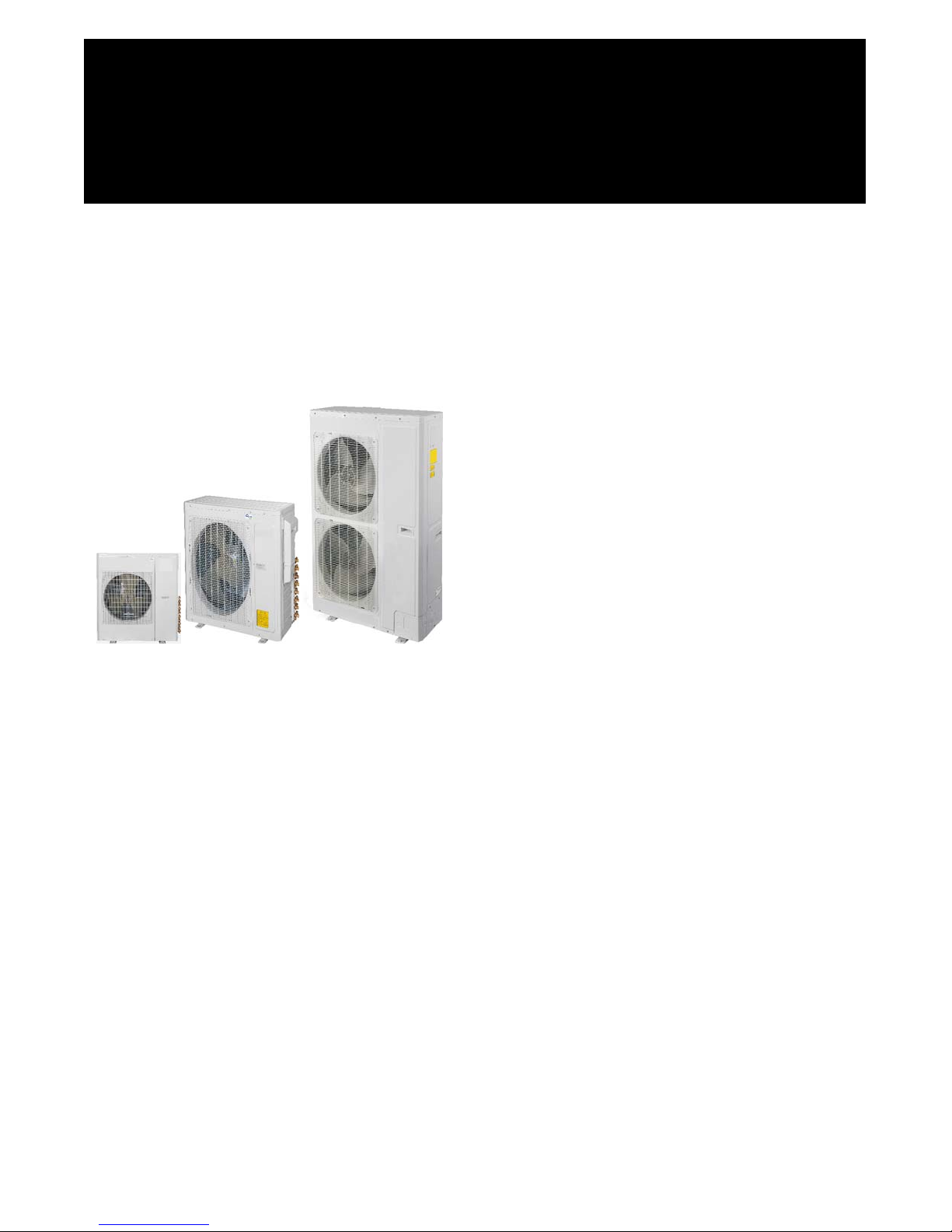
DLCBHR / DLFAHH / DLFBHB / DLFBHC / DLFBHD / DLFBHF
Multi- Zone Ductless Split System
Size 18K, 24K, 30K, 36K, 42K, 48K and 56K
Installation Instructions
NOTE: Read the entire instruction manual before starting the installation.
TABLE OF CONTENTS
SAFETY CONSIDERATIONS 2.........................
PAGE
GENERAL 2.........................................
SYSTEM REQUIREMENTS 3- 4.........................
ELECTRICAL DATA 4................................
PARTS LIST 6........................................
DIMENSIONS 7- 14...................................
CLEARANCES 15- 17.................................
DIMENSIONS - BRANCH BOXES 18- 19.................
INSTALLATION GUIDE 20.............................
HIGH- WALL INDOOR UNIT INSTALLATION 20..........
DUCTED INDOOR UNITS INSTALLATION 21............
FLOOR CONSOLE INDOOR UNITS INSTALLATION 24....
INSTALLING THE INDOOR UNIT 26....................
CASSETTE TYPE INDOOR UNIT INSTALLATION 28......
OUTDOOR UNIT INSTALLATION 31....................
SYSTEM VACUUM AND CHARGE 35...................
START- UP 37........................................
TROUBLESHOOTING 38- 41...........................

SAFETY CONSIDERATIONS
Installing, starting up, and servicing air- conditioning equipment
can be hazardous due to system pressures, electrical components,
and equipment location (roofs, elevated structures, etc.).
Only trained, qualified installers and service mechanics should
install, start-up, and service this equipment.
Untrained personnel can perform basic maintenance functions such
as cleaning coils. All other operations should be performed by
trained service personnel.
When working on the equipment, observe precautions in the
literature and on tags, stickers, and labels attached to the
equipment.
Follow all safety codes. Wear safety glasses and work gloves. Keep
quenching cloth and fire extinguisher nearby when brazing. Use
care in handling, rigging, and setting bulky equipment.
Read these instructions thoroughly and follow all warnings or
cautions included in literature and attached to the unit. Consult
local building codes and current editions of the National Electrical
Code ( NEC ) NFPA 70. In Canada, refer to current editions of the
Canadian electrical code CSA 22.1.
!
Recognize safety information. This is the safety- alert symbol
When you see this symbol on the unit and in instructions or
manuals, be alert to the potential for personal injury. Understand
these signal words: DANGER, WARNING, and CAUTION.
These words are used with the safety- alert symbol. DANGER
identifies the most serious hazards which will result in severe
personal injury or death. WARNING signifies hazards which could
result in personal injury or death. CAUTION is used to identify
unsafe practices which may result in minor personal injury or
product and property damage. NOTE is used to highlight
suggestions which will result in enhanced installation, reliability, or
operation.
!
!
ELECTRICAL SHOCK HAZARD
Failure to follow this warning could result in personal
injury or death.
Before installing, modifying, or servicing system, main
electrical disconnect switch must be in the OFF
position. There may be more than 1 disconnect switch.
Lock out and tag switch with a suitable warning label.
!
EQUIPMENT DAMAGE HAZARD
Failure to follow this caution may result in equipment
damage or improper operation.
Do not bury more than 36 in. (914 mm) of refrigerant pipe
in the ground. If any section of pipe is buried, there must be
.
a 6 in. (152 mm) vertical rise to the valve connections on
the outdoor units. If more than the recommended length is
buried, refrigerant may migrate to the cooler buried section
during extended periods of system shutdown. This causes
refrigerant slugging and could possibly damage the
compressor at start- up.
WARNING
CAUTION
GENERAL
These instructions cover the inst allati on, start-up and servic i ng of the
multi-zone outdoor unit connec t ed to up to nine indoor fan coil units .
For approved combinations, please refer to the Product Data.
2
SYSTEM REQUIREMENTS
Allow sufficient space for airflow and servicing unit. See Fig. 14 through 19 for minimum required clearances.
Piping
IMPORTANT: Both refrigerant lines must be insulated separately.
Minimum refrigerant line length between the indoor and outdoor units is 10 ft. (3 m). The following maximum lengths are allowed:
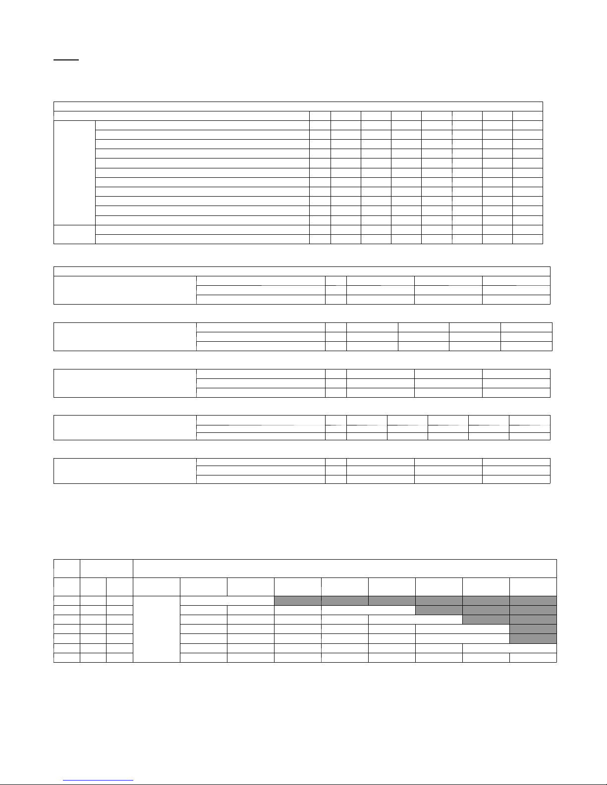
Table 1—Maximum Piping Lengths
System Size 18 24 30 36 42 48 56
Piping
Refrigerant
Min. Piping Length ft 10 10 10 10 10 10 10
Standard Piping Length ft 32 98 131.2 131.2 131.2 98.42 98.42
Max. outdoor-indoor height difference ft 33 33 49.2 49.2 49.2 98.42 98.42
Max. height distance between indoor and indoor ft 33 33 24.6 24.6 24.6 49.21 49.21
Max. height distance between indoor and outdoor and indoor ft 32 32 49.2 49.2 49.2 98.42 98.42
Max. height distance between indoor and outdoor and outdoor up ft 33 33 49.2 49.2 49.2 98.42 98.42
Max. equivalent piping outdoor to last indoor ft 33 65 82 82 82 229 229
Max. Piping Length with no additional refrigerant charge ft 32 98 131.2 131.2 131.2 98.42 98.42
Max. Piping Length ft 65 196 229.7 246 246 442.9 475.7
Gas Pipe (size - connection type) in 3/8 3/8 3/8 3/8 3/8 5/8 5/8
Liquid Pipe (size - connection type) in 1/4 1/4 1/4 1/4 1/4 3/8 3/8
Refrigerant Type R-410A R-410A R-410A R-410A R-410A R-410A R-410A
Heat Pump Models Charge Amount Lbs 3.53 4.85 6.17 8.05 8.05 10.91 10.91
NOTE: Tables 2 through 6 show the piping size specifications.
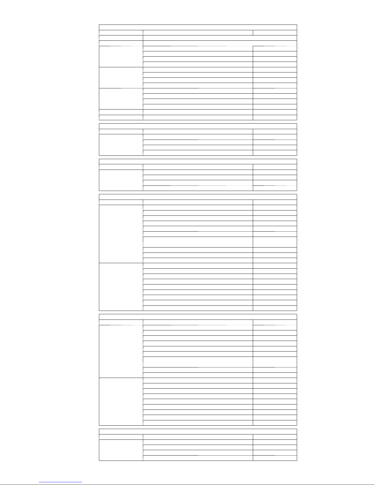
Indoor Unit Piping Connection Sizes
Indoor High Wall
(DLFAHH)
Indoor High Wall
(DLFBHB)
Indoor Cassette
Indoor Ducted
Size 9 12 18
Pipe Connection Size - Liquid In. 1/4" 1/4" 1/4"
Pipe Connection Size - Suction In. 1/2" 1/2" 5/8"
Size 9 12 18 24
Pipe Connection Size - Liquid In. 1/4" 1/4" 1/4" 1/4"
Pipe Connection Size - Suction In. 1/2" 1/2" 5/8" 5/8"
Size 12 18 24
Pipe Connection Size - Liquid In. 1/4" 1/4" 3/8"
Pipe Connection Size - Suction In. 3/8" 1/2" 5/8"
Size 9 12 18 21 24
Pipe Connection Size - Liquid In. 1/4" 1/4" 1/4" 3/8" 3/8"
Pipe Connection Size - Suction In. 3/8" 3/8" 1/2" 5/8" 5/8"
Table 6—Indoor Floor Console
Size 9 12 18
Indoor Floor Console
Pipe Connection Size - Liquid In. 1/4" 1/4" 1/4"
Pipe Connection Size - Suction In. 3/8" 3/8" 1/2"
Refrigerant Piping:
Line sets to be sized based on the connection size of the indoor unit. Each pipe to be insulated individually.
Conversion Joints:
The outdoor unit may include a package of conversion joints to facilitate installation of various sizes of fan coils. These joints are to be
connected to the outdoor unit as needed to match the line set size.
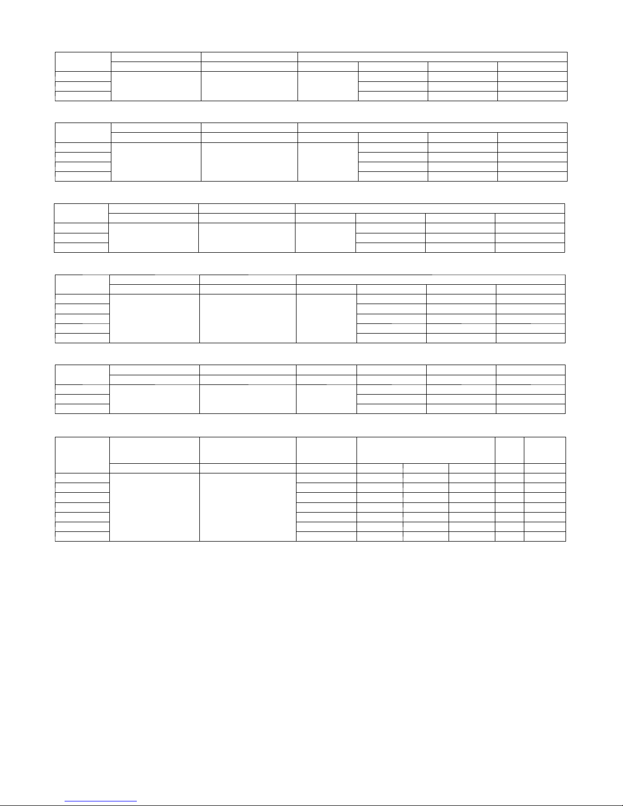
Table 7—Additional Refrigerant Charge
Total Line
Unit
Size
Length ft
Min Max
18 10 66
24 10 196 None None 0.20 / 0.20 0.20 / 0.20
30 10 230 None None None 0.24 / 0.58 0.24 / 0.58
36 10 246 None None None 0.24 / 0.58 0.24 / 0.58 0.24 / 0.58
42 10 246 None None None 0.24 / 0.58 0.24 / 0.58 0.24 / 0.58
48 10 443 None None 0.24 / 0.58 0.24 / 0.58 0.24 / 0.58 0.24 / 0.58 0.24 / 0.58
56 10 476 None None 0.24 / 0.58 0.24 / 0.58 0.24 / 0.58 0.24 / 0.58 0.24 / 0.58 0.24 / 0.58
10 - 32
(3 - 10)
None
>32 - 66
(10 - 20)
Additional Charge, 1/4” Liquid Line / 3/8” Liquid Line, oz/ft. ft (m)
>66 - 98
(20 - 30)
0.20 / 0.20
Outdoor Unit
Table 2—Indoor High Wall
Table 3—Indoor High Wall
Table 4—Indoor Cassette
Table 5—Indoor Ducted
>98 - 131.2
(30 - 40)
>131.2 - 196
(40 - 60)
>196 - 230
(60 - 70)
>230 - 246
(70 - 75)
>246 - 443
(75 - 135)
>443 - 476
(135 - 145)
Additional Refrigerant Calculation Sizes 30K, 36K and 42K:
Sum Total Liquid Pipe 1/4” (ft) x 0.24 + Sum Total Pipe 3/8” (ft) x 0.58 – 31 oz
Additional Refrigerant Calculation Sizes 48K and 56K:
Sum Total Liquid Pipe 1/4” (ft) x 0.24 + Sum Total Pipe 3/8” (ft) x 0.58 – 51.7 oz
NOTE: If the calculation results in a negative number no additional refrigerant is required.
NOTES:
EXV = Electronic Expansion Device
Electronic expansion valves in the outdoor unit are used as metering devices.
3
ELECTRICAL DATA
Table 8—High Wall DLFAHH
UNIT SIZE
9
12 0.1 0.0268 20
18 0.1 0.0268 20
UNIT SIZE
9
12 0.17 1/72 10
18 0.3 1/29 25
24 0.38 1/10 70
UNIT SIZE
12
18 0.18 1/72 46
24 0.43 1/20 46
UNIT SIZE
9
12 0.31 1/18 80
18 0.41 1/12 100
21 0.5 1/36' 124
24 0.5 1/36' 124
SYSTEM VOLTAGE OPERATINGVOLTAGE INDOORFAN
VOLT / PHASE / HZ MAX / MIN V-PH-HZ FLA HP W
0.1 0.0268 20
208-230/1/60 253 / 187 208-230/1/60
Table 9—High Wall DLFBHB
System Voltage OPERATING VOLTAGE INDOOR FAN
VOLT / PHASE / HZ MAX / MIN V-PH-HZ FLA HP W
0.17 1/72 10
208-230/1/60 253 / 187 208-230/1/60
Table 10—Cassette
System Voltage OPERATING VOLTAGE INDOORFAN
VOLT / PHASE / HZ MAX / MIN V-PH-HZ FLA HP W
0.18 1/72 46
208-230/1/60 253 / 187 208-230/1/60
Table 11—Ducted
System Voltage OPERATING VOLTAGE INDOORFAN
VOLT / PHASE / HZ MAX / MIN V-PH-HZ FLA HP W
0.28 1/24 80
208-230/1/60 253 / 187 208-230/1/60
Table 12—Floor Console
UNIT SIZE
9
12 0.14 1/24 30
18 0.14 1/24 30
System Voltage OPERATING VOLTAGE INDOOR FAN
VOLT / PHASE / HZ MAX / MIN V-PH-HZ FLA HP W
0.14 1/24 30
208-230/1/60 253 / 187 208-230/1/60
Table 13—Multi Zone Outdoor Unit
UNIT SIZE
18
24 11.5 0.59 1/8 90 21 35
30 13.9 0.68 1/6 150 19 30
36 15.6 0.82 2/9 240 21 35
42 17.8 0.82 2/9 240 24 40
48 23 1 1/6 150 30 50
56 23 1 1/6 150 30 50
*Permissible limits of the voltage range at which the unit will operate satisfactorily.
LEGEND
FLA - Full Load Amps
LRA - Locked Rotor Amps
MCA - Minimum Circuit Amps
RLA - Rated Load Amps
System Voltage OPERATING VOLTAGE COMPRESSOR OUTDOOR FAN MCA
VOLT / PHASE / HZ MAX / MIN RLA FLA HP W
7.2 0.62 1/12 60 15 25
208-230/1/60 253 / 187
MAX
FUSE/CB
AMP
4
!
EQUIPMENT DAMAGE HAZARD
Failure to follow this caution may result in equipment
damage or improper operation.
S Wires should be sized based on NEC and local codes.
S Use copper conductors only with a minimum 300 volt .
rating and 2/64 inch thick insulation.
!
EQUIPMENT DAMAGE HAZARD
Failure to follow this caution may result in equipment damage
or improper operation.
S Be sure to comply with local codes while running wire from
indoor unit to outdoor unit.
S Every wire must be connected firmly. Loose wiring may
cause terminal to overheat or result in unit malfunction. A
fire hazard may also exist. Therefore, be sure all wiring is
tightly connected.
S No wire should be allowed to touch refrigerant tubing,
compressor or any moving parts.
S Disconnecting means must be provided and shall be located
within sight and readily accessible from the air conditioner.
S Connecting cable with conduit shall be routed through hole
in the conduit panel.
All wires must be sized per NEC (National Electrical Code) or
CEC (Canadian Electrical Code) and local codes. Use Electrical
Data table MCA (minimum circuit amps) and MOCP (maximum
over current protection) to correctly size the wires and the
disconnect fuse or breakers respectively.
Per caution note, only copper conductors with a minimum 300
volt rating and 2/64- inch thick insulation must be used. The u se
of BX cable is not recommended.
18- 42
Sizes
Recomme nde d Connection Method for Power and
Communication - Wi r ing - Power and Communication Wiri ng:
The main power is supplied to the outdoor unit. The field supplied
14/3 power/communication wiring from the outdoor unit to indoor
unit consists of four (4) wires and provides the power for the
indoor unit. Two wires are high voltage AC power; one is
communication wiring and the other is a ground wire.
CAUTION
CAUTION
Recomme nde d Connection Method for Power and
Communication Wiring (To minimize communication wiring
interference)
Power Wiring:
The main power is supplied to the outdoor unit. The fie l d supplied
power wiring from the outdoor unit to indoor unit consists of three (3)
wires and provides the power for the indoor unit. Two wires are high
voltage AC powe r and one is a ground wi re. To mini mize voltage
drop, the fac tory recommended wir e size is 14/2 stranded with a
ground.
Communication Wiring:
A separate shielded copper conductor only, with a minimum 300
volt rating and 2/64- inch thick insulation, must be used as the
communication wire from the outdoor unit to the indoor unit.
Please use a separate shielded 16GA stranded control wire.
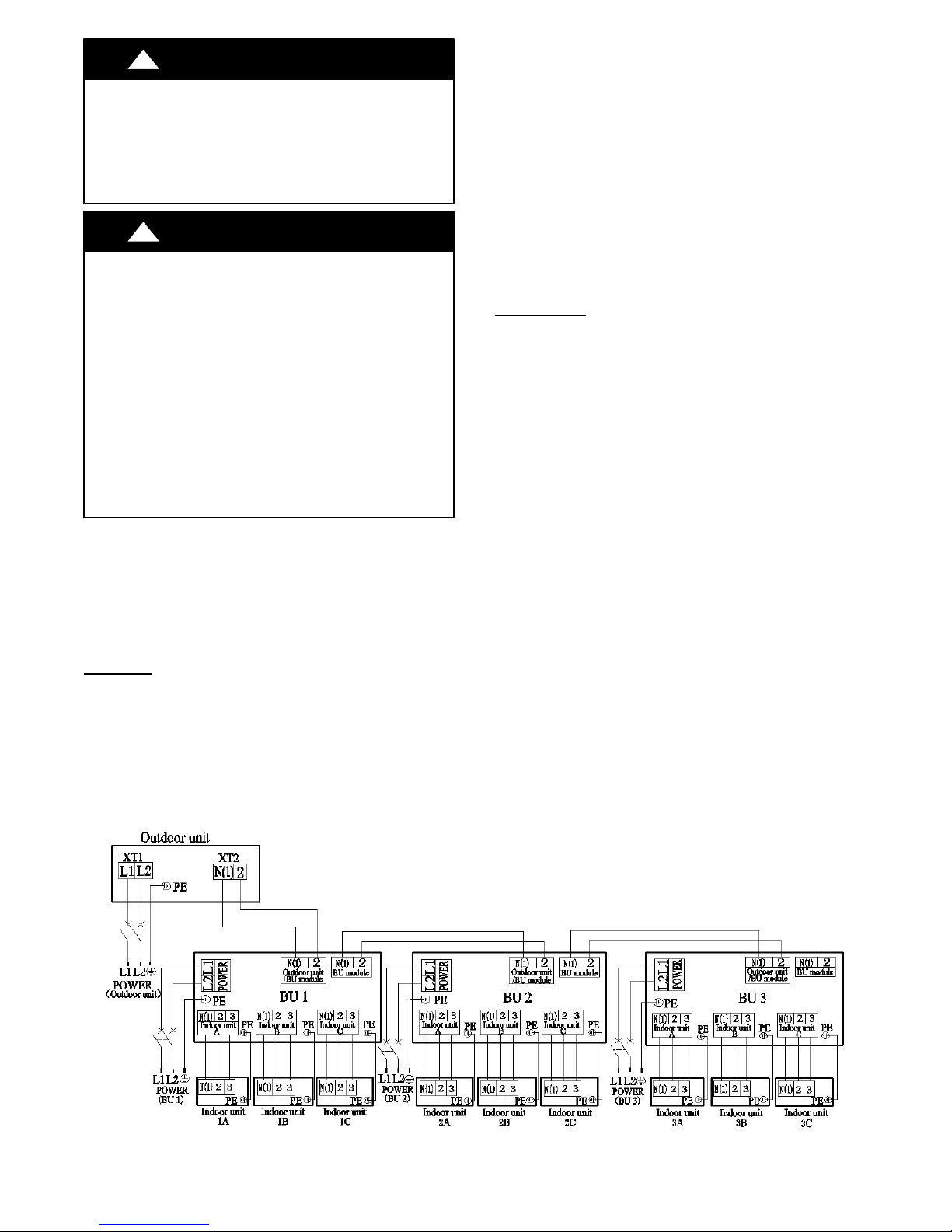
For sizes
Recomme nde d Connection Method for Power and
Communication - Wi r ing - Power and Communication Wiri ng:
Power Wiri ng OUTDOOR UNIT& BRANCH BOXES:
Separate power s upplies ar e required for t he outdoor unit and the
Branch Boxes. The indoor units are powered from the Branch Boxes.
The field supplied 14/3 power wiring from the OUTDOOR UNIT
consists of three (3) wires. Two wires are high voltage AC power, one
is a ground wire.
The field supplied 14/3 power wiring from the BRANCH BOXES
consists of three (3) wires. Two wires are high voltage AC power, one
is a ground wire.
Up to three (3) Branch Boxes can be powered from the same 15 amp
breaker.
Communication Wiring:
A separate shiel ded copper conductor only, with a minimum 300 volt
rating and 2/64- inch thick insulati on, must be used as the
communication wire from the OUTDOOR UNIT to the BRANCH
BOX.
Please use a separate shielded 16GA stranded control wire.
Power and Communication Wiring BRANCH BOXES to
INDOOR UNITS:
The field supplied 14/3 power/communication wiring from the
BRANCH BOX to the INDOOR UNIT consists of f our (4) wires
and provides the power for the indoor unit. Two wires are high
voltage AC power, one is communicat i on wiring “2” and the other is
a ground wire “N(1)”
See diagr am below for detai ls on wiring for size s 48- 56.
48- 56
Fig. 1 - Wiring Connection
5
PARTS LIST
Size Name Qty
18 No parts included
24 No parts included
30
36
42
48 bellows φ16 1
56 bellows φ16 1
Size Name Qty
9,12,18
Size Name Qty
9,12,18,24
Size Name Qty
12,18
24
Size Name Qty
9,12,18
21,24
Size Name Qty
9,12,18
Outdoor Units
Conversion Joint 3/8 to 5/8 2
Conversion Joint 3/8 to 1/2 4
Conversion Joint 1/4 to 3/8 2
Screw M4X12 1
Conversion Joint 3/8 to 5/8 2
Conversion Joint 3/8 to 1/2 4
Conversion Joint 1/4 to 3/8 2
Screw M4X12 1
Conversion Joint 3/8 to 5/8 2
Conversion Joint 3/8 to 1/2 4
Conversion Joint 1/4 to 3/8 2
Screw M4X12 1
Indoor High Wall DLFAHH
Mounting Plate 1
Remote Control 1
Remote Control Holder 1
Battery (1.5V) 2
Indoor High Wall DLFBHB
Mounting Plate 1
Remote Control 1
Remote Control Holder 1
Battery (1.5V) 2
Indoor Cassette
Remote control 1
Battery (1.5V) 2
GasketM6Xφ18X1.4 4
GasketM10Xφ30X2.5 10
Screw ST4.8X13 HC 4
Screw M6X25 4
Nut of Connector Pipe(B)
Package
Pipe Connection Nut ("I" shape) 1
Connection wire of wired control 1
Wired controller 1
bellows φ16 1
Connection wire of wired control 1
Remote control 1
Battery (1.5V) 2
Gasket location board 1
Screw ST4.8X13 HC 4
Gasket 10 10
Nut of Connector Pipe(B) 1
Wired controller 1
Indoor Ducted
Remote control 1
Battery (1.5V) 2
Screw M10X8 4
Screw M10 4
Gasket 10GB93 4
Pipe Connection Nut ("I" shape) 1
Nut of Connector Pipe(B)
Package
Wired control 1
Connection wire of wired control 1
Remote control 1
Battery (1.5V) 2
Screw M10X8 4
Screw M10 4
Gasket 10GB93 4
Nut of Connector Pipe(B) 1
Wired controller 1
Connection wire of wired control 1
bellows φ16 1
Indoor Floor Console
Installation Panel 1
Remote Control 1
Remote Control Holder 1
Battery (1.5V) 2
1
1
6
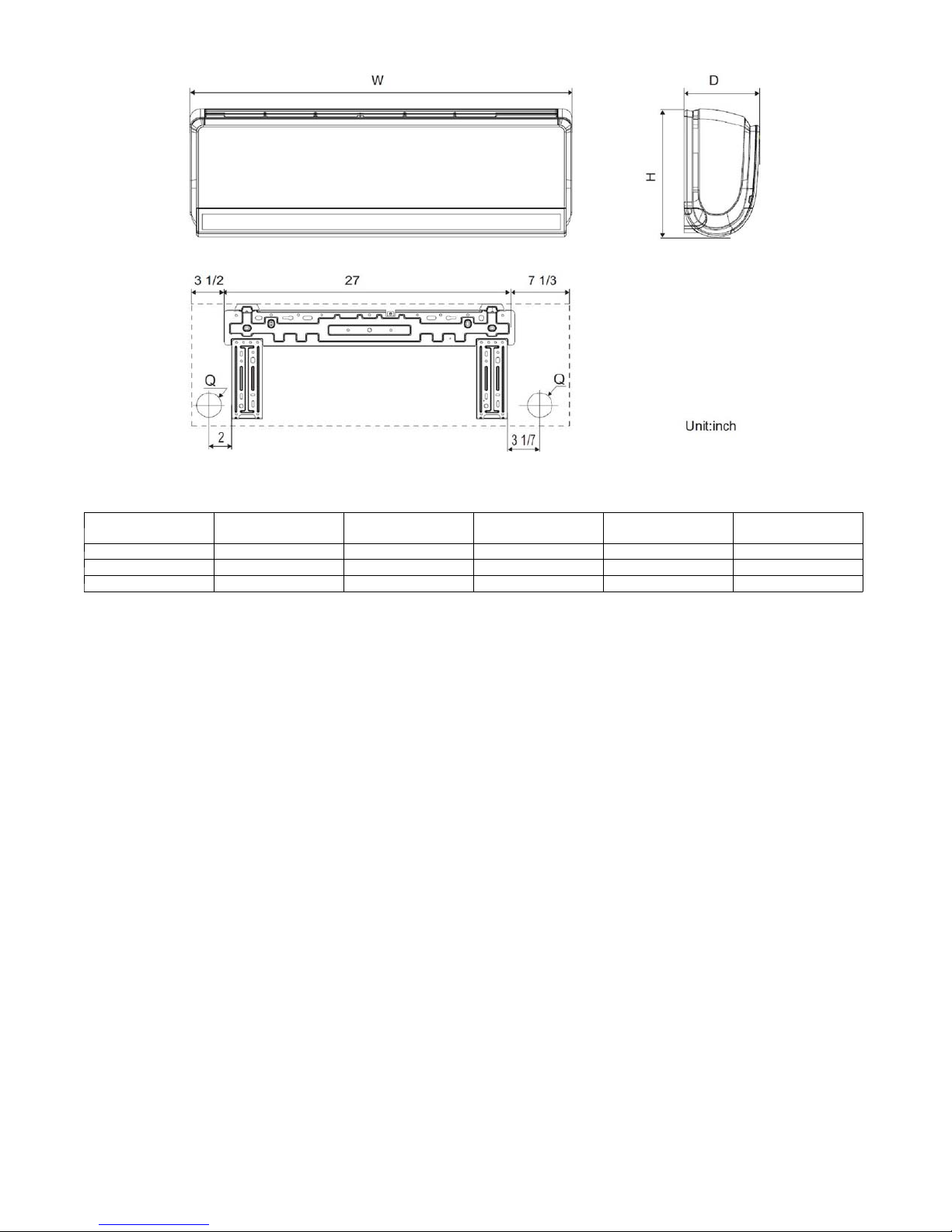
DIMENSIONS - INDOOR
Fig. 2 - High Wall Dimensions
Table 14—High Wall DLFAHH Dimensions
Unit Size W In. (mm) D In. (mm) H In. (mm) Q In. (mm)
9k 37.8 (960)g 8.07 (205) 12.6 (320) 2.16 (55) 33.07 (15)
12k 37.8 (960) 8.07 (205) 12.6 (320) 2.16 (55) 33.07 (15)
18k 37.8 (960) 8.07 (205) 12.6 (320) 2.75 (70) 33.07 (15)
Operating Weight
Lbs. (kg)
7
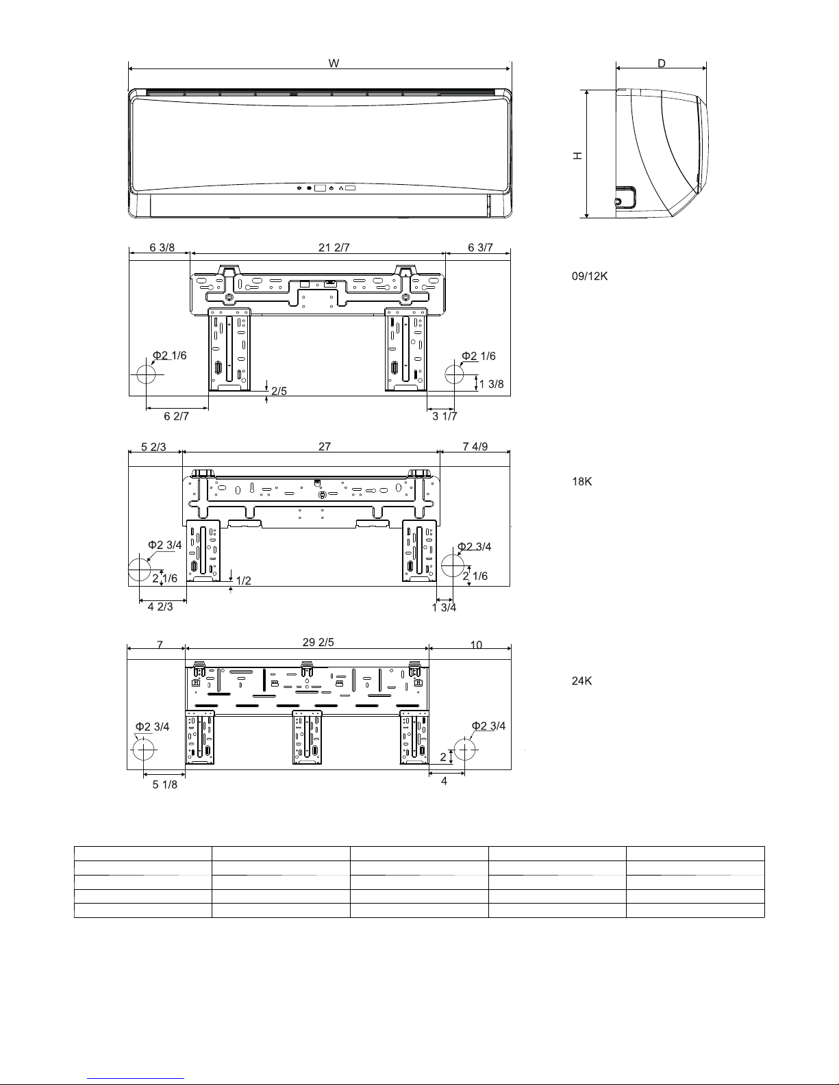
DIMENSIONS - INDOOR (CONTINUED)
Unit Size W In. (mm) D In (mm) H In. (mm) Operating Weight
9k 34.09 8.23 11.5 24.3
12k 34.09 8.23 11.5 24.3
18k 40.079 9.055 12.6 30.9
24 46.378 10.394 12.8 38.6
Fig. 3 - Wall Dimensions
Table 15—High Wall DLFBHB
8
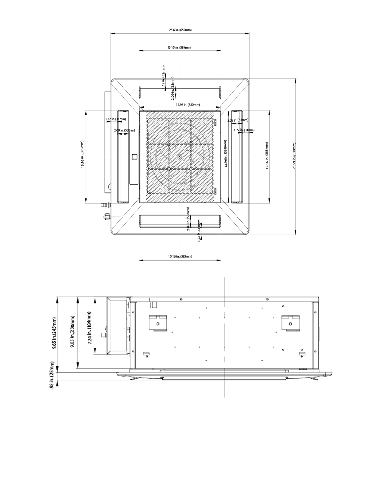
DIMENSIONS - INDOOR (CONTINUED)
Fig. 4 - Cassette Grill Dimensions
Fig. 5 - Cassette Side View Dimensions
9
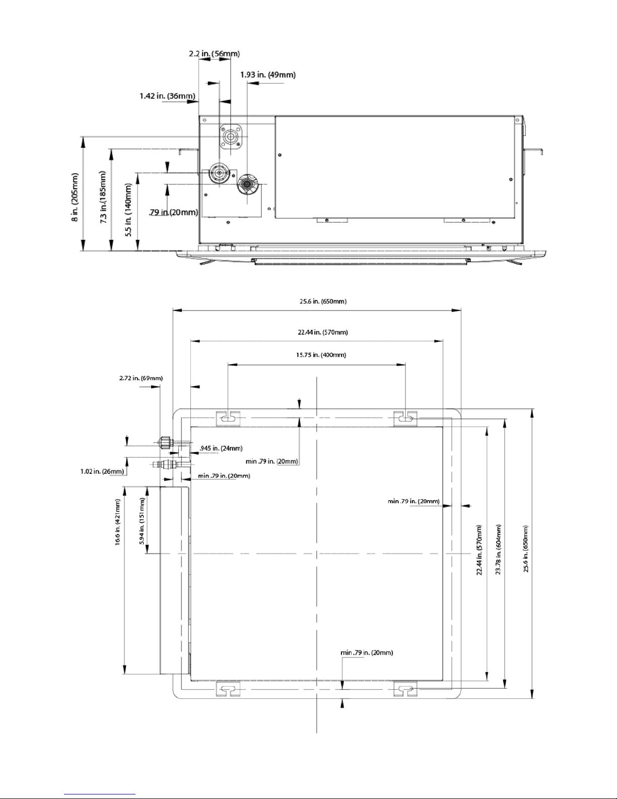
DIMENSIONS - INDOOR (CONTINUED)
Fig. 6 - Cassette Connection Side View Dimensions
Fig. 7 - Cassette Top View Dimensions
10
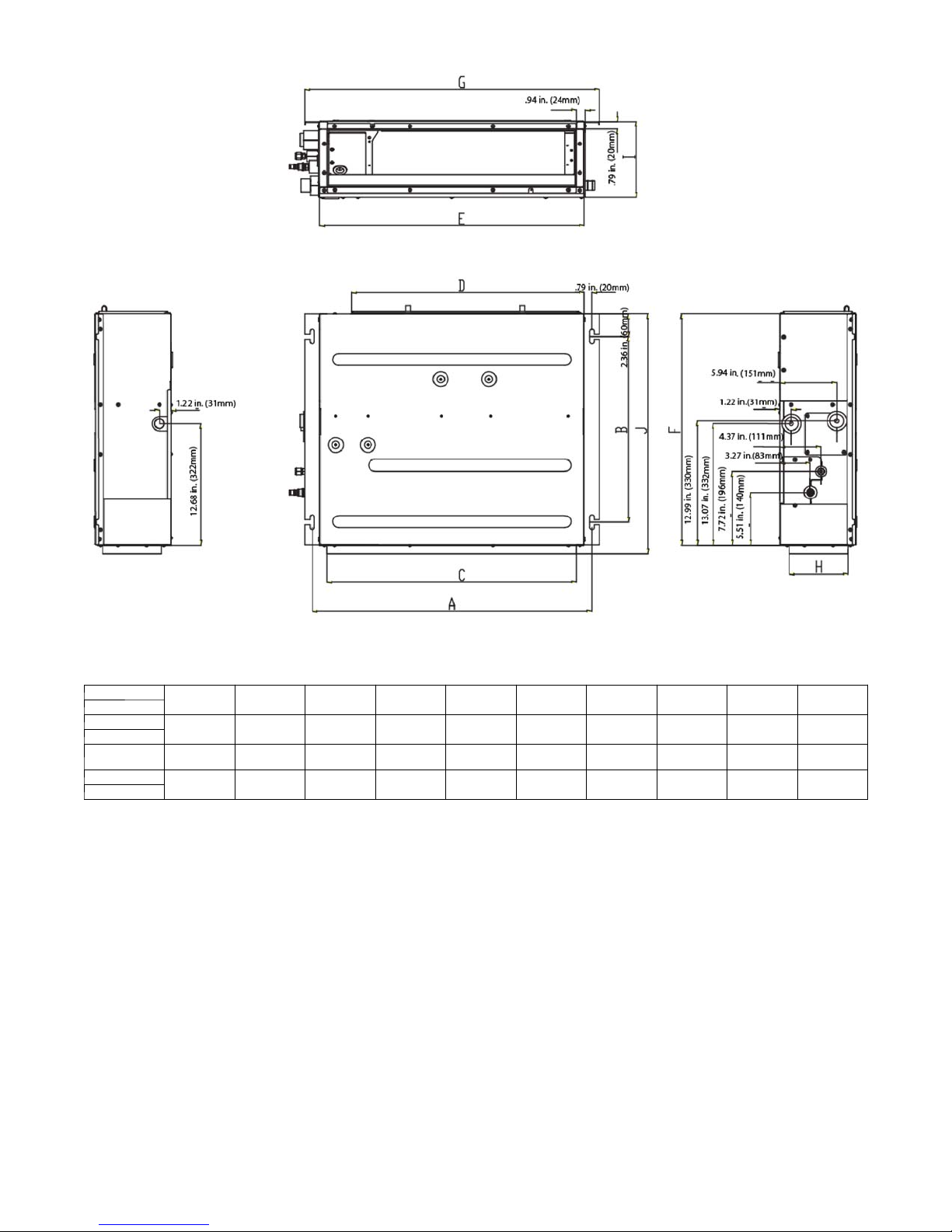
DIMENSIONS - INDOOR (CONTINUED)
Item
Size
09
12
18
21
24
Fig. 8 - Ducted Dimensions
Table 16—Outline Dimensions
A B C D E F G H I J
29 1/5 in
(742 mm)
37 in
(942 mm)
45 in
(1142 mm)
19 1/3 in
(491 mm)
19 1/3 in
(491 mm)
19 1/3 in
(491 mm)
26 in
(662 mm)
34 in
(862 mm)
41 4/5 in
(1062 mm)
24 2/5 in
(620 mm)
32 2/7 in
(820 mm)
40 1/6 in
(1020 mm)
27 5/9 in
(700 mm)
35 3/7 in
(900 mm)
43 1/3 in
(1100 mm)
24 1/5 in
(615 mm)
24 1/5 in
(615 mm)
24 1/5 in
(615 mm)
30 4/5 in
(782 mm)
38 2/3 in
(982 mm)
46 1/2 in
(1182 mm)
6 1/7 in
(156 mm)
6 1/7 in
(156 mm)
6 1/7 in
(156 mm)
7 7/8 in
(200 mm)
7 7/8 in
(200 mm)
7 7/8 in
(200 mm)
25 in
(635 mm)
25 in
(635 mm)
25 in
(635 mm)
11
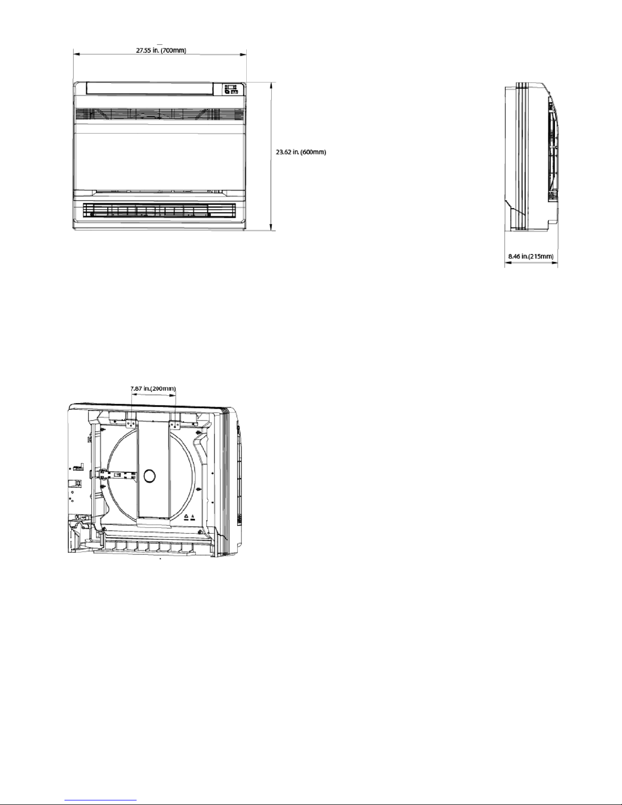
DIMENSIONS - INDOOR (CONTINUED)
Fig. 9 - Floor Console Dimensions
12
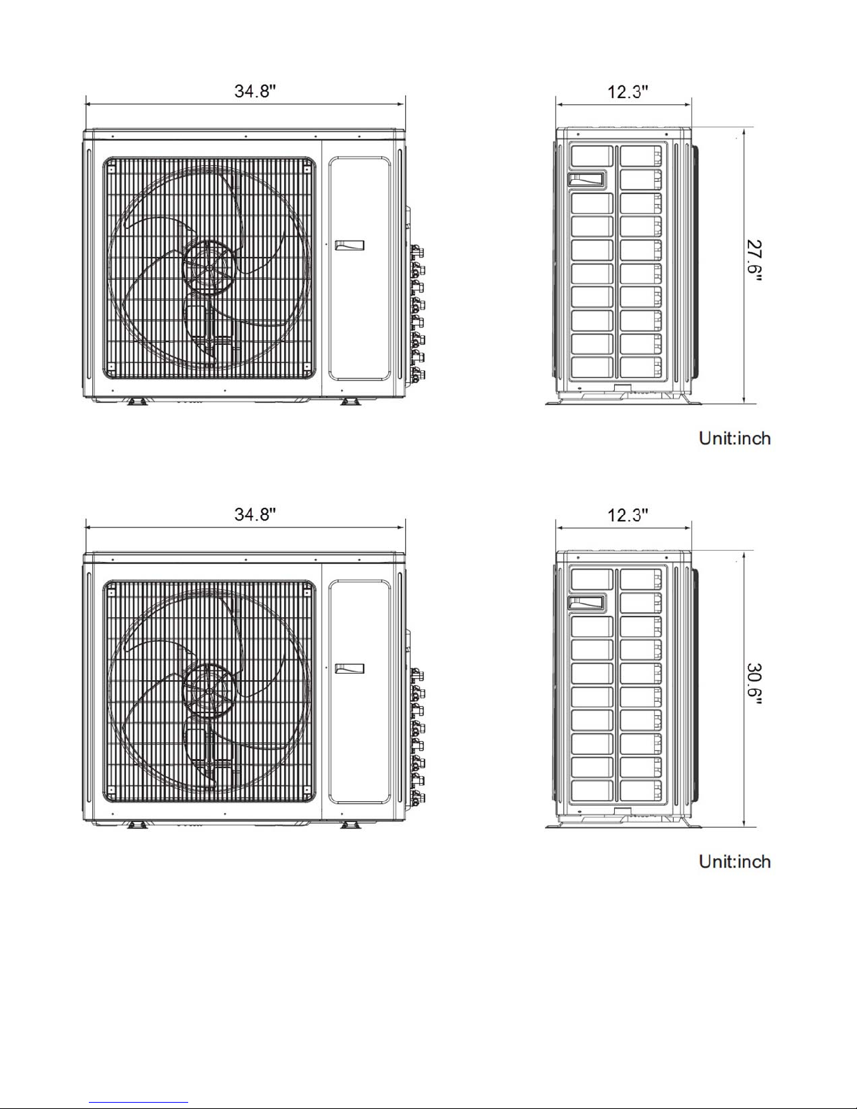
DIMENSIONS - OUTDOOR
Fig. 10 - Outdoor Dimensions Size 18
Fig. 11 - Outdoor Dimensions Size 24
13
 Loading...