

International comfort products CAC075, CAC090, CAE075, CAC120, CAE090 Installation Instructions Manual
Installation
Instructions
SPLIT SYSTEM
3 PHASE 6.3 to 10 TON
AC CONDENSERS
Save This Manual for Future Reference
501 01 1504 00
11/13/01
Installation/ Startup Information
These instructions must be read and understood completely before attempting installation.
Split System CondensersInstallation Instructions
WARNING
Installation or repairs made by unqualified
persons can result in hazards to you and others.
Installation MUST conform with local building
codes or, in the absence of local codes, with the
the National Electrical Code NFPA 70/ANSI
C1-1999 or current edition and Canadian
Electrical Code Part 1 CSA C.22.1.
The information contained in this manual is
intended for use by a qualified service technician
familiar with safety procedures and equipped
with the proper tools and test instruments.
Failure to carefully read and follow all instructions in this manual can result in equipment
malfunction, property damage, personal injury
and/or death.
After uncrating unit, inspect thoroughly for hidden damage.
If damage is found, notify the transportation company immediately and file a concealed damage claim.
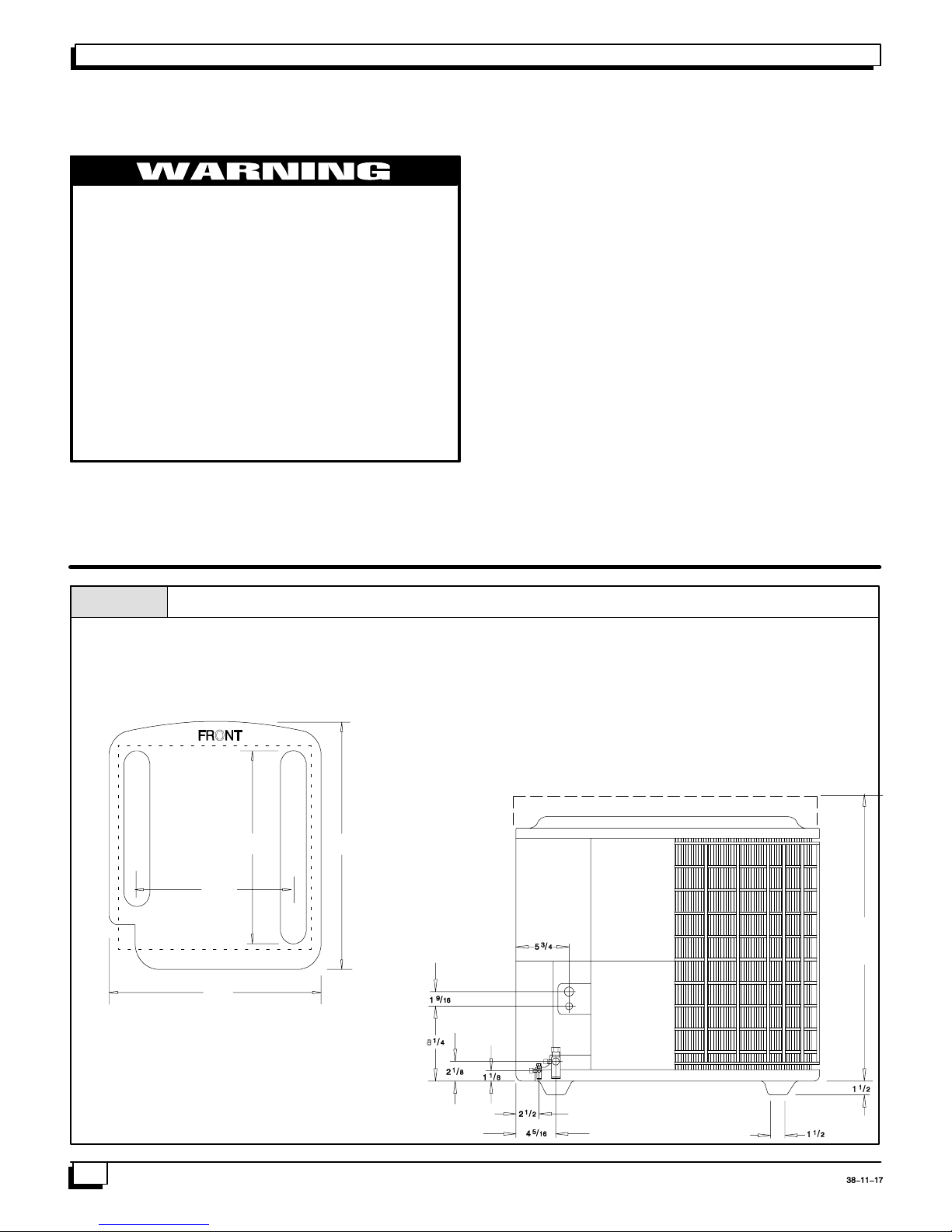
Figure 1
Dimensions
CAUTION
Improper installation, adjustment, alteration, service or
maintenance can void the warranty.
The weight of the condensing unit requires caution and
proper handling procedures when lifting or moving to avoid
personal injury. Use care to avoid contact with sharp or
pointed edges.
Safety Precautions
1. Always wear safety eye wear and work gloves when
installing equipment.
2. Never assume electrical power is disconnected. Check
with meter and disconnect.
3. Keep hands out of fan areas when power is connected
to equipment.
4. R--22 causes frost--bite burns.
5. R--22 is toxic when burned.
NOTE TO INSTALLING DEALER: The Owners Instructions and Warranty are to be given to the owner or prominently displayed near the indoor Furnace/Air Handler Unit.
24
33
Chassis #3
27
Minimum Mounting Pad Sizes with pad starting at
9” from structure for minimum clearances
Chassis #3 27” W X 28” D
“H” = Ranges from 26” to 44”
Refer to Specification Sheet
35
H
2
501 01 1504 00
Split System Condensers Installation Instructions
Locating The Outdoor Unit:
Check local codes covering zoning, noise, platforms.
If practical, avoid locating next to fresh air intakes, vent or
bedroom windows. Noise may carry into the openings and
disturb people inside.
Placement of the unit should be in a well drained area or
unit must be supported high enough so runoff will not enter
the unit.
Do not locate where heat, lint or exhaust fumes will be discharged on unit (as from dryer vents).
Clearances:
Nominal operating clearances, where practical, are 48
inches (120 cm) above unit for discharge air and 18 inches
(40cm) around coil for intake air on three sides. Clearance
on one side (normally between unit and structure) may be
reduced to 6inches (15cm). Nominal clearances are based
from a solid parallel object, wall, roof overhang, etc.
Do Not install under roof overhangs without guttering. A
minimum vertical clearance of 48” is required to overhang.
The clearance may be reduced from a single object with a
small surface area, such as the end of a wall, outside corner of a wall, fence section or a post, etc. As a general rule
the width ofthe object should equal the minimum clearance
from the unit. For example, a 4 inch (10cm) fence post
could be 4 inches (10cm) from the unit.
Roof top installations are acceptable providing the roof will
support the unit and provisions are made for water drainage and the noise or vibration through the structure.
Do not install the unit in a recessed or confined area where
recirculation of discharge air may occur.
Heat Pumps Only: The top surface of platform must be
above average winter snow levels to prevent coil blockage.
Inside corner locations on single story structures require
evaluation. Large overhanging soffits may cause air recirculation in a corner area even though recommended clearances are maintained. As a guide locate theunit far enough
out so that half of the discharge grille is out from under the
soffit.
Two or more units may be spaced with 18 inches (45cm)
between units.
A service clearance of 24 inches (60cm) is desirable from
control box end or side. Control box and corner panel below it can be loosened and moved out to the side to facilitate servicing. Internal components can be accessed
through control box corner or top only.
Unit Support:
The unit must be level, and supported above grade by
beams, platform or apad. Platform or padcan be of open or
solid construction but should be of permanent materials
such as concrete, bricks, blocks, steel or pressure treated
timbers approved for ground contact. Refer to Unit Clearances to help determine size of supports etc. Soil conditions should be considered so the platform or pad does not
shift or settle excessively and leave the unit only partially
supported.
CAUTION
Inadequate support could cause excessive vibration and
noise or binding and stress on refrigerant lines resulting in
equipment failure.
To minimize vibration or noise transmission, it is recommended that supports not be in contact with the building
structure. However, slabs on grade constructions with an
extended pad are normally acceptable.
A. Ground Level Installation:
If beams or an open platform are used for support it is recommended that the soil be treated or area be graveled to
retard the growth of grasses and weeds.
B. Roof Top Installation:
This type of installation is not recommended on wood
frame structures where low noise levels are required.
Supporting structure or platform for the unit must be level. If
installation is on a flat roof the unit should be 4 inches
(10cm.) above roof level. Four by four posts placed over a
load bearing wall make a suitable mounting platform.
If possible, place the unit over one or more load bearing
walls. If there are several units, mount them on platforms
that are self--supporting and span load bearing walls.
These suggestions are to minimize noise and vibration
transmission through the structure. If the structure is a
home or apartment, avoid (if practical) locating the unit
over bedrooms or study.
NOTE: When condensing unit is to be installed on a
bonded guaranteed roof, a release must be obtained from
the building owner to free the installer from all liabilities.
501 01 1504 00
3
Split System CondensersInstallation Instructions
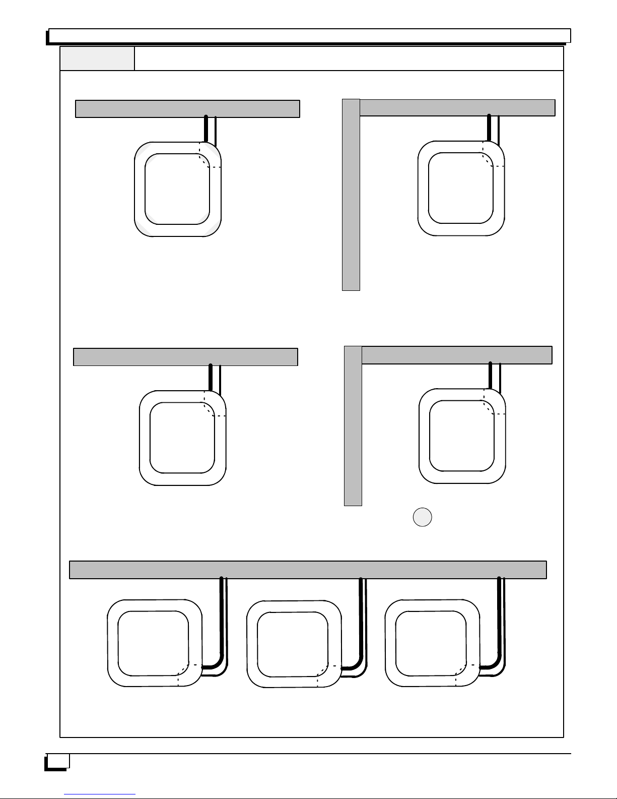
ClearancesFigure 2
Recommended Clearances
Full Wall
6”
24”
24”
Minimum Clearances
Full Wall
6”
24”
Full Wall
Minimum Clearances
Full Wall
6”
24”
24”
Minimum Clearances
Full Wall
6”
24”
24”
18”
24”
6”
18”
24”
Minimum Clearances
Full Wall
6”
18”
24”
Half Wall
18”
18”
6”
Pipe
24”
6”
18”
6”
24”
24”
4
501 01 1504 00
 Loading...