

International comfort products N8MPL050B12, N8MPL075B12, N8MPL075F16, N8MPL100F20, N8MPL100J22 Installation Instructions Manual
...
CARBON MONOXIDE POISONING AND FIRE
HAZARD
Failure to follow this warning could result in
personal injury, death, and/or property damage.
This furnace is not designed for use in mobile
homes, trailers or recreational vehicles.
!
ELECTRIC SHOCK HAZARD
Failure to follow this warning
could result in injury and/or
death.
Turn OFF all power, lockout and
tag with suitable warning label
before servicing.
!
International Comfort Products, LLC
Lewisburg, TN 37091 U.S.A.
See section 5 for Category I definition.
INSTALLER: Affix these instructions
on or adjacent to the furnace.
CONSUMER: Retain these
instructions for future reference.
Portions of the text and tables are reprinted from ANSI Z223.1/NFPA 54!2009, with permission of National Fire Protection Association, Quincy, MA 02269 and American Gas Association, Wash-
ington, DC 20001. This reprinted material is not the complete and official position of the NFPA or ANSI, on the referenced subject, which is represented only by the standard in its entirety.
WARNING
WARNING
WARNING
* Denotes Brands (C, H, T)
Printed in U.S.A. 441 01 2613 05 Sept. 2009
80+ SINGLE STAGE GAS FURNACE
Category I Furnace
N8MPN/N8MPL & *8MPN/*8MPL
Upflow/Downflow/Horizontal
SAFETY CONSIDERATIONS
Improper installation, adjustment, alteration, service, maintenance, or use can cause explosion, fire, electrical shock, or other conditions
which may cause death, personal injury, or property damage. Consult a qualified installer, service agency, or your distributor or branch for
information or assistance. The qualified installer or agency must use factory!authorized kits or accessories when modifying this product.
Refer to the individual instructions packaged with the kits or accessories when installing.
Follow all safety codes. Wear safety glasses, protective clothing, and work gloves. Use quenching cloth for brazing operations. Have fire
extinguisher available. Read these instructions thoroughly and follow all warnings or cautions included in literature and attached to the unit.
Consult local building codes, the current editions of the National Fuel Gas Code (NFCG) NFPA 54/ANSI Z223.1, National Electrical Code
(NEC) NFPA 70.
In Canada refer to the current editions of the National standards of Canada CAN/CSA!B149.1 and .2 Natural Gas and Propane Installation
Codes, and Canadian Electrical Code CSA C22.1.
Recognize safety information. This is the safety!alert symbol
. When you see this symbol on the unit and in instructions or manuals, be
alert to the potential for personal injury. Understand these signal words; DANGER, WARNING, and CAUTION. These words are used with
the safety!alert symbol. DANGER identifies the most serious hazards which will result in severe personal injury or death. WARNING
signifies hazards which could result in personal injury or death. CAUTION is used to identify unsafe practices which may result in minor
personal injury or product and property damage. NOTE is used to highlight suggestions which will result in enhanced installation, reliability,
or operation.
Table of Contents
1. Safe Installation Requirements 3. . . . . . . . . . . . . . . .
2. Installation 4. . . . . . . . . . . . . . . . . . . . . . . . . . . . . . . .
3. Side Venting 8. . . . . . . . . . . . . . . . . . . . . . . . . . . . . . .
4. Combustion & Ventilation Air 9. . . . . . . . . . . . . . . . . .
5. Gas Vent Installation 12. . . . . . . . . . . . . . . . . . . . . . . .
6. Horizontal Venting 13. . . . . . . . . . . . . . . . . . . . . . . . .
7. Masonry Chimney Venting 15. . . . . . . . . . . . . . . . . . .
8. Gas Supply and Piping 18. . . . . . . . . . . . . . . . . . . . . .
9. Electrical Wiring 21. . . . . . . . . . . . . . . . . . . . . . . . . . .
10.Ductwork and Filter (Upflow/Horizontal) 22. . . . . . . .
11.Ductwork and Filter (Downflow) 25. . . . . . . . . . . . . . . .
12. Checks and Adjustments 27. . . . . . . . . . . . . . . . . . . . . .
13. Furnace Maintenance 32. . . . . . . . . . . . . . . . . . . . . . . .
14. Sequence of Operation & Diagnostics 33. . . . . . . . . . . .
15.Technical Support Manual 35. . . . . . . . . . . . . . . . . . . . .
16.Model Specificications 36. . . . . . . . . . . . . . . . . . . . . . . .
17.Circulation Data & Bellyband Placement 31. . . . . . . . . .
18.Wiring Diagram 42. . . . . . . . . . . . . . . . . . . . . . . . . . . . .
19.Parts Information Guide 43. . . . . . . . . . . . . . . . . . . . . .
National Excelsior Company
www.excelsiorhvac.com
Subject to change without notice.

2
441 01 2613 05
Specifications are subject to change without notice
START!UP CHECK SHEET
For 80+ Furnace
(This sheet is optional. Keep this page for future reference.)
Date of Start!Up:
Dealer Name:
Address:
City, State(Province), Zip or Postal Code:
Phone:
Owner Name:
Address:
City, State(Province), Zip or Postal Code:
Model Number:
Serial Number:
Setup Checks
Check the box when task is complete
Thermostat: Heat
Cooling Fan
Subbase level:
Anticipator Set: Setting of Anticipator ____
All Electrical Connections Tight:
Supply voltage: ____
Blower Motor H.P.: ____
Fan “Time ON” setting: ____ Fan “Time OFF” Setting ___
Manual Gas Shut!Off Upstream of Furnace/Drip!Leg?
Gas Valve turned ON?
Type of Gas: Natural: Propane:
Filter Type and Size:
Calculated Firing Rate:(See Checks and Adjustments
Section).
Heating Check
Measured Line Pressure when Firing Unit:
Measured Manifold Gas Pressure:
Temperature of Supply Air: (°)
Temperature of Return Air: (°)
Temperature Rise (supply!return temperature): (°)
In Rise (see furnace rating plate)? (°)
Static Pressure (Ducts): Supply Air Return
Blower speed tap used for heating
Limit Opens: (°) Limit Closes: (°)
Optional Check: CO ? CO2 ?
Cooling Check
Temperature of Supply Air: (°)
Temperature of Return Air: (°)
Temperature Difference: (°)
Static Pressure (Ducts) cooling: Supply Air Return
Blower Speed Tap used for cooling: _______
Dealer Comments:
National Excelsior Company
www.excelsiorhvac.com
Subject to change without notice.
441 01 2613 05
3
Specifications are subject to change without notice
1. Safe Installation Requirements
FIRE, EXPLOSION, AND ASPHIXIATION HAZARD
Improper adjustment, alteration, service,
maintance or installation could cause personal
injury, death, and/or property damage.
Installation or repairs made by unqualified persons
could result in hazards to you and others.
Installation MUST conform with local codes or, in
the absence of local codes, with codes of all
governmental authorities having jurisdiction.
The information contained in this manual is
intended for use by a qualified service agency that
is experienced in such work, is familiar with all
precautions and safety procedures required in
such work, and is equipped with the proper tools
and test instruments.
!
WARNING
NOTE: This furnace is design!certified by the CSA International
(formerly AGA and CGA) for installation in the United States and
Canada. Refer to the appropriate codes, along with this manual,
for proper installation.
• Use only the Type of gas approved for this furnace (see
Rating Plate on unit). Overfiring will result in failure of heat
exchanger and cause dangerous operation. (Furnaces
can be converted to Propane gas with approved kit.)
• Install this furnace only in a location and position as
specified in “Installation” of these instructions.
• Provide adequate combustion and ventilation air to the
furnace as specified in “Combustion and Ventilation Air” of
these instructions.
• Combustion products must be discharged outdoors.
Connect this furnace to an approved vent system only, as
specified in “Gas Vent Installation, Horizontal Venting and
Masonry Chimney Venting” of these instructions.
• Never test for gas leaks with an open flame. Use a
commercially available soap solution made specifically for
the detection of leaks to check all connections, as
specified in “Gas Supply and Piping, Final Check” of these
instructions.
• Always install furnace to operate within the furnace’s
intended temperature!rise range with a duct system which
has an external static pressure within the allowable range,
as specified in “Technical Support Manual” of these
instructions. See furnace rating plate.
• When a furnace is installed so that supply ducts carry air
circulated by the furnace to areas outside the space
containing the furnace, the return air shall also be handled
by a duct(s) sealed to the furnace casing and terminating
outside the space containing the furnace.
• A gas!fired furnace for installation in a residential garage
must be installed as specified in “Installation” of these
instructions.
• This furnace is not to be used for temporary heating of
buildings or structures under construction.
• This furnace is NOT approved for installation in
mobile homes, trailers or recreation vehicles.
• Seal around supply and return air ducts.
• Install correct filter type and size.
• Unit MUST be installed so electrical components are
protected from direct contact with water.
Safety Rules
Your unit is built to provide many years of safe and dependable
service providing it is properly installed and maintained. However,
abuse and/or improper use can shorten the life of the unit and
create hazards for you, the owner.
A. The U.S. Consumer Product Safety Commission encourages
installation of carbon monoxide alarms. There can be various
sources of carbon monoxide in a building or dwelling. The
sources could be gas!fired clothes dryers, gas cooking
stoves, water heaters, furnaces, gas!fired fireplaces, wood
fireplaces.
Carbon monoxide can cause serious bodily injury and/or
death. Carbon monoxide or “CO” is a colorless and odorless
gas produced when fuel is not burned completely or when the
flame does not receive sufficient oxygen.
Therefore, to help alert people of potentially dangerous carbon
monoxide levels, you should have a commercially available
carbon monoxide alarm that is listed by a nationally
recognized testing agency in accordance with Underwriters
Laboratories Inc. Standard for Single and Multiple Station
Carbon Monoxide Alarms, ANSI/UL 2034 or the CSA 6.19!01
Residential Carbon Alarming Devices installed and
maintained in the building or dwelling concurrently with the
gas!fired furnace installation (see Note below). The alarm
should be installed as recommended by the alarm
manufacturer’s installation instructions.
B. There can be numerous sources of fire or smoke in a building
or dwelling. Fire or smoke can cause serious bodily injury,
death, and/or property damage. Therefore, in order to alert
people of potentially dangerous fire or smoke, you should have
fire extinguisher and smoke alarms listed by Underwriters
Laboratories installed and maintained in the building or
dwelling (see Note below).
Note: The manufacturer of your furnace does not test any alarms
and makes no representations regarding any brand or type
of alarms.
C. To ensure safe and efficient operation of your unit, you should
do the following:
1. Thoroughly read this manual and labels on the unit. This
will help you understand how your unit operates and the
hazards involved with gas and electricity.
2. Do not use this unit if any part has been under water.
Immediately call a qualified service agency to inspect the unit
and to replace any part of the control system and any gas
control which has been under water.
3. Never obstruct the vent grilles, or any ducts that provide
air to the unit. Air must be provided for proper combustion and
ventilation of flue gases.
Frozen Water Pipe Hazard
WATER DAMAGE TO PROPERTY HAZARD
FaiIure to follow this warning could result in
property damage.
Do not leave your home unattended for long periods
during freezing weather without turning off water
supply and draining water pipes or otherwise
protecting against the risk of frozen pipes and
resultant damage.
!
WARNING
National Excelsior Company
www.excelsiorhvac.com
Subject to change without notice.
4
441 01 2613 05
Specifications are subject to change without notice
Your furnace is designed solely to provide a safe and comfortable
living environment. The furnace is NOT designed to ensure that
water pipes will not freeze. It is equipped with several safety
devices that are designed to turn the furnace off and prevent it from
restarting in the event of various potentially unsafe conditions.
If your furnace remains off for an extended time, the pipes in your
home could freeze and burst, resulting in serious water damage.
If the structure will be unattended during cold weather you should
take these precautions.
1. Turn off the water supply to the structure and drain the water
lines if possible and add an antifreeze for potable water to
drain traps and toilet tanks. Open faucets in appropriate
areas.
!or!
2. Have someone check the structure frequently during cold
weather to make sure it is warm enough to prevent pipes
from freezing. Instruct them on a service agency to call to
provide service, if required.
!or!
3. Install a reliable remote sensing device that will notify
somebody of freezing conditions within the home.
2. Installation
CARBON MONOXIDE POISONING HAZARD
Failure to follow this warning could result in
personal injury or death.
If this furnace is replacing a previously common-
vented furnace, it may be necessary to resize the
existing vent system to prevent oversizing
problems for the other remaining appliances(s).
See Venting and Combustion Air Check in the Gas
Vent Installation section of this instruction.
!
WARNING
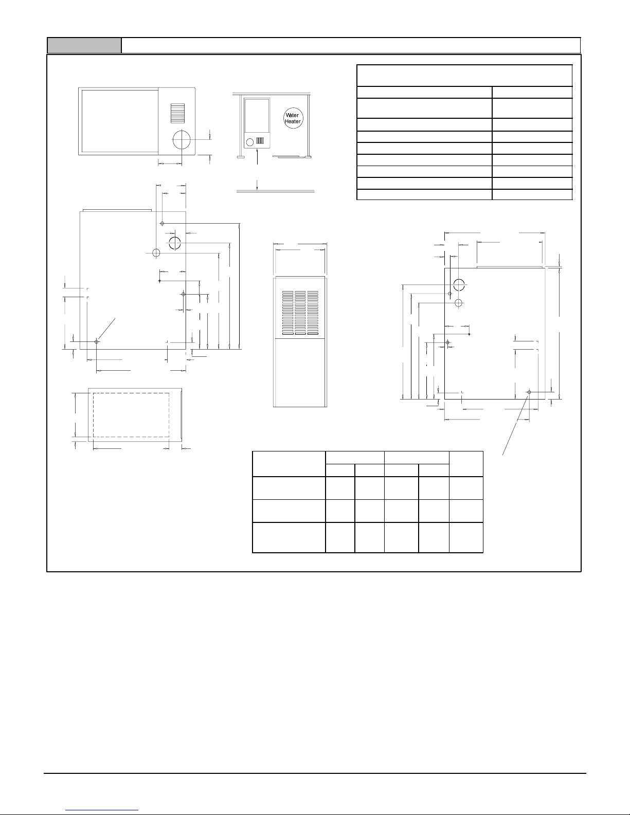
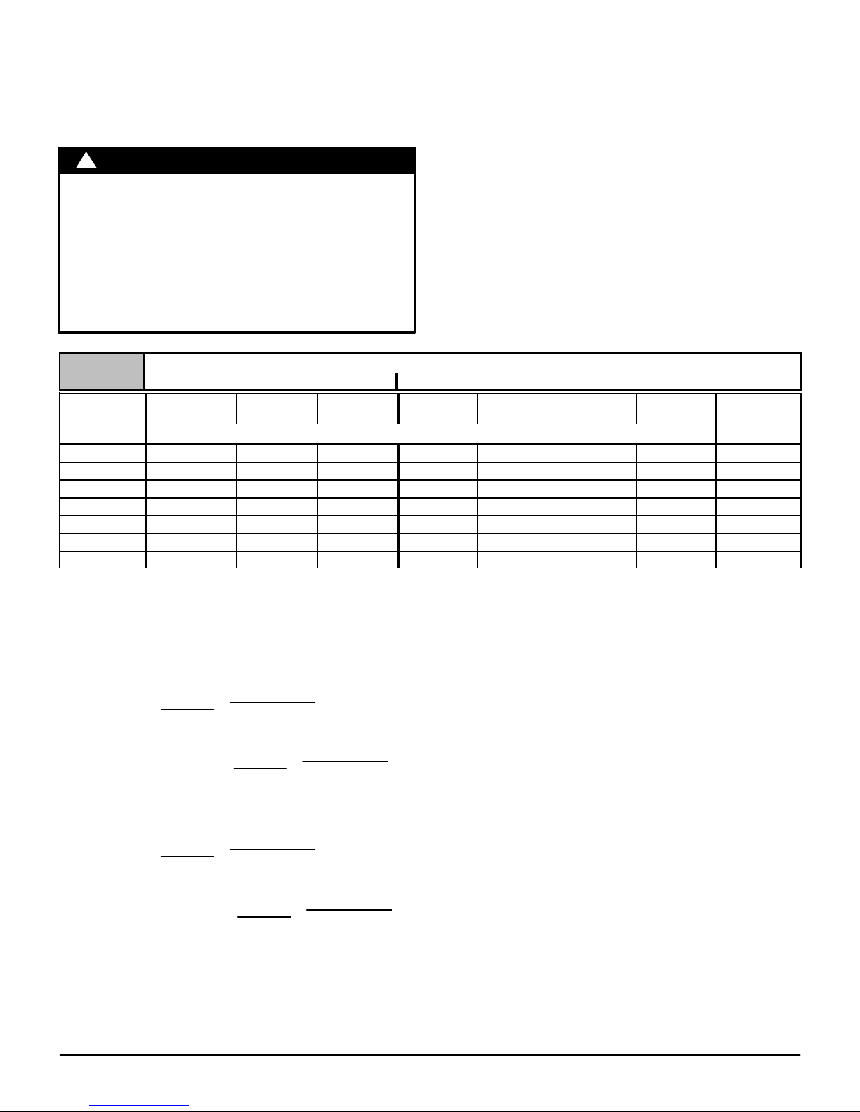
Location and Clearances
If furnace is a replacement, it is usually best to install the furnace
where the old one was. Choose the location or evaluate the
existing location based upon the minimum clearance and furnace
dimensions (Figure 1 or Figure 2).
CARBON MONOXIDE POISONING HAZARD
Failure to follow this warning could result in
personal injury or death.
Do NOT operate furnace in a corrosive
atmosphere containing chlorine, fluorine or any
other damaging chemicals which could harm the
furnace and vent system, and permit spillage of
combustion products into an occupied space.
Refer to Combustion & Ventilation Air section,
Contaminated Combustion Air for combustion air
evaluation and remedy.
!
WARNING
Installation Requirements
1. Install furnace level.
2. This furnace is NOT to be used for temporary heat of buildings
or structures under construction.
3. Install furnace as centralized as practical with respect to the
heat distribution system.
4. Install the vent pipes as short as practical. (See Gas Vent
Installation section).
5. Do NOT install furnace directly on carpeting, tile or other
combustible material other than wood flooring.
6. Maintain clearance for fire safety and servicing. A front
clearance of 24″ (609.6mm) required and 30″ (762mm) is
recommended for access to the burner, controls and filter. See
clearance requirements in Figure 1 or Figure 2.
7. Use a raised base if the floor is damp or wet at times.
8. Residential garage installations require:
• Burners and ignition sources installed at least 18″
(457.2mm) above the floor.
• Furnace must be located or physically protected from
possible damage by a vehicle.
9. If the furnace is to be suspended from the floor joists in a
basement or a crawl space or the rafters in an attic, it is
necessary to use steel pipe straps or an angle iron frame to
attach the furnace. These straps should be attached to the
furnace bottom side with sheet metal screws and to the rafters
or joists with bolts. The preferred method is to use an angle iron
frame bolted to the rafters or joists.
10. This furnace may be used for construction heat provided that:
• The furnace is permanently installed with all electrical
wiring, piping, venting and ducting installed according to
these installation instructions. A return air duct is
provided, sealed to the furnace casing, and terminated
outside the space containing the furnace. This prevents
a negative pressure condition as created by the
circulating air blower, causing a flame rollout and/or
drawing combustion products into the structure.
• The furnace is controlled by a thermostat. It may not be
“hot wired” to provide heat continuously to the structure
without thermostatic control.
• Clean outside air is provided for combustion. This is to
minimize the corrosive effects of adhesives, sealers and
other construction materials. It also prevents the
entrainment of drywall dust into combustion air, which
can cause fouling and plugging of furnace components.
• The temperature of the return air to the furnace is
maintained between 55° F (13° C) and 80° F (27° C) , with
no evening setback or shutdown. The use of the furnace
while the structure is under construction is deemed to be
intermittent operation per our installation instructions.
• The air temperature rise is within the rated rise range on
the furnace rating plate, and the firing rate has been set to
the rating plate value.
• The filters used to clean the circulating air during the
construction process must be either changed or
thoroughly cleaned prior to occupancy.
• The furnace, ductwork and filters are cleaned as
necessary to remove drywall dust and construction
debris from all HVAC system components after
construction is completed.
• Verify proper furnace operating conditions including
ignition, gas input rate, air temperature rise, and venting
according to these installation instructions.
National Excelsior Company
www.excelsiorhvac.com
Subject to change without notice.
Drawing is representative, but some models may vary
NOTE: Evaporator “A” coil drain pan dimensions
may vary from furnace duct opening size. Always
consult evaporator specifications for duct size
requirements.
Unit is designed for bottom return or side return.
Return air through back of unit is NOT allowed.
131/
4
281/
2
33/
4
171/
3
21/
4
TOP
51/
3
31/
4
LEFT SIDE
61/
2
33/
4
5
271/
2
33
131/
4
241/
2
17/
8
213/
4
265/
8
131/
4
47/
8
11/
2
7
1
RIGHT SIDE
281/
2
181/
2
21/
4
131/
4
171/
3
3
/
4
2
7
1
35
32
213/
4
11/
2
253/
4
47/
8
265/
8
17/
8
FRONT
A
B
30″ Min.
BOTTOM
D
C
231/
8
41/
16
J
H
Plugged starting
hole to cut side
duct opening
Plugged starting
hole to cut side
duct opening
ALL DIMENSIONS in(mm)
1 in = 25.4 mm
(724)
(470)
(19)
(57)
(337)
(178)
(470)
(676)
(124)
(48)
(889)
(95)
(51)
(813)
(654)
(337)
(440)
(38)
(95)
(127)
(178)
(124)
(48)
(337)
(838)
(670)
(622)
(337)
(440)
(38)
(552)
(57)
(762)
(587)
(103)
(83)
(25)
(552)
(165)
(676)
(135)
441 01 2613 05
5
Specifications are subject to change without notice
Figure 1 Dimensions and Clearances N8MPN/L
MINIMUM CLEARANCES TO
COMBUSTIBLE MATERIALS FOR ALL UNITS
REAR 0
FRONT (combustion air openings
in furnace and in structure)
3″ (76 mm)
Required For Service
*30″ (762 mm)
ALL SIDES Of SUPPLY PLENUM 1″ (25 mm)
SIDES 0
VENT
Single Wall Vent 6″ (152 mm)
Type B!1 Double Wall Vent 1″ (25 mm)
TOP OF FURNACE 1″ (25 mm)
Horizontal position: Line contact is permissible only between lines
formed by intersections of top and two sides of furnace jacket, and
building joists, studs or framing.
DIMENSIONAL INFORMATION
Unit
Capacity
Cabinet Bottom
Duct
Size
A B C D
N8MPL050B12
N8MPL075B12
151/
2
(76)
14
(356)
13/
8
(1.4)
125/
8
(321)
H
N8MPL075F16
N8MPL100F20
191/
8
(486)
175/
8
(447)
21/
8
(54)
143/
4
(15)
J
N8MPL100J22
N8MPL125J20
N8MPL125J22
223/
4
(578)
211/
4
(540)
115/
16
(49)
183/
4
(476)
J
National Excelsior Company
www.excelsiorhvac.com
Subject to change without notice.

331/
2
303/
4
291/
2
175/
16
33/
4
21/
4
13/
4
47/
8
21/
4
47/
8
271/
2
175/
16
321/
2
277/
8
NOTE: Evaporator “A” coil drain pan dimensions may vary from
furnace duct opening size. Always consult evaporator specifica
tions for duct size requirements.
Furnace is designed for bottom return or side return.
Return air through back of furnace is NOT allowed.
ALL DIMENSIONS - in(mm)
1 in = 25.4 mm
D
C
231/
8
41/
16
24″ (610) min.
51/
3
F
TOP
111/
16
1
5
38
7
265/
8
131/
4
217/
8
17/
8
33/
4
LEFT SIDE
A
B
FRONT
BOTTOM
RIGHT SIDE
7
1
37
2
40
181/
2
281/
2
131/
4
3
/
4
261/
2
215/
8
17/
8
Plugged starting hole
to cut side duct opening..
Plugged starting hole
to cut side duct opening..
J
H
Drawing is representative, but some models may vary
(135)
(127)
(95)
(365)
(826)
(708)
(699)
(440)
(43)
(124)
(556)
(676)
(587)
(48)
(337)
(57)
(178)
(103)
(25)
(57)
(470)
(724)
(19)
(51)
(95)
(178)
(25)
(940)
(781)
(851)
(749)
(440)
(45)
(124)
(542)
(673)
(337)
(48)
(1016)
6
441 01 2613 05
Specifications are subject to change without notice
Figure 2 Dimensions and Clearances *8MPN/L Models
MINIMUM CLEARANCES TO
COMBUSTIBLE MATERIALS FOR ALL UNITS
REAR 0
FRONT (combustion air openings in
furnace and in structure)
3″ (76 mm)
Required For Service
*24″ (610 mm)
ALL SIDES Of SUPPLY PLENUM 1″ (25 mm)
SIDES 0
VENT
Single Wall Vent 6″ (152 mm)
Type B!1 Double Wall Vent 1″ (25 mm)
TOP OF FURNACE 1″ (25 mm)
*30″ (762 mm) clearance recommended for furnace removal.
Horizontal position: Line contact is permissible only between lines
formed by intersections of top and two sides of furnace jacket, and
building joists, studs or framing.
Furnace
Capacity
Cabinet Top Bottom
Return
Air
Opening
A B F C D
*8MPL050B12
*8MPL075B12
151/
2
(394)
14
(356)6(152)
13/
8
(35)
125/
8
(321)
H
*8MPL075F16
*8MPL100F20
191/
8
(486)
171/
2
(445)
73/
4
(197)
21/
8
(54)
143/
4
(375)
J
*8MPL100J22
*8MPL125J20
223/
4
(578)
211/
4
(540)
91/
2
(241)
115/
16
(49)
183/
4
(476)
J
* Denotes Brand (C, H, T)
Installation Positions
This furnace can be installed in an upflow, horizontal (either left or
right) or downflow airflow position. DO NOT install this furnace on
its back. For the upflow position, the return air ductwork can be
attached to either the left or right side panel and/or the bottom. For
horizontal and downflow positions, the return air ductwork must be
attached to the bottom. The return air ductwork must never be
attached to the back of the furnace.
Furnace Installation
Inspect the rating plate to be certain the model number begins with
“N8MP” or “*8MP”. This identifies the unit as a multi!position
furnace and can be Installed in a Upflow, Horizontal Right,
Horizontal Left or Downflow position.
* Dentoes Brand (C, H, T)
Upflow
No modifications are required for upflow installation. (See
Figure 3)
National Excelsior Company
www.excelsiorhvac.com
Subject to change without notice.
441 01 2613 05
7
Specifications are subject to change without notice
Typical Upflow Installation
Figure 3
25!23!17
VENT
SUPPLY
AIR
GAS SUPPLY
RETURN
AIR
Horizontal
If you purchased a multi!position furnace, it can be installed
horizontally in an attic, basement, crawl space, alcove, or
suspended from a ceiling in a basement or utility room in either a
right or left airflow position. (see Figure 4)
Horizontally installed furnaces may be vented out the top of the
unit or out the side facing up. See “Side venting” for instructions to
rotate the vent to the side.
The minimum clearances to combustibles MUST be maintained
between the furnace and adjacent construction, as shown in
Figure 1 and Figure 2. ONLY the corner of the cabinet is allowed
to contact the rafters as shown in Figure 4. All other clearances
MUST be observed as shown in Figure 1 and Figure 2.
Typical Horizontal Installation
Figure 4
VENT
VENT
GAS SUPPLY
SUPPLY
AIR
RETURN
AIR
25-23-18a
OPTIONAL
VENT LOCATION
If the furnace is to be suspended from the floor joists in a basement
or crawl space or the rafters in an attic, it is necessary to use steel
pipe straps or an angle iron frame to attach the furnace. These
straps should be attached to the furnace bottom side with sheet
metal screws and to the rafters or joists with bolts. The preferred
method is to use an angle iron frame bolted to the rafters or joists.
If the furnace is to be installed at ground level in a crawl space,
consult local codes. A concrete pad 1″ to 2″ (25.4 to 50.8mm) thick
is recommended.
24″ (609.6mm) is required between the front of the furnace and
adjacent construction or other appliances. This should be
maintained for service clearance.
Keep all insulating materials clear from louvered door. Insulating
materials may be combustible.
The horizontal furnaces may be installed directly on combustible
wood flooring or supports, however, it is recommended for further
fire protection cement board or sheet metal is placed between the
furnace and the combustible wood floor and extend 12″
(304.8mm) beyond the front of the furnace louver door. (This is a
recommendation only, not a requirement).
This furnace MUST NOT be installed directly on carpeting, tile or
other combustible material other than wood flooring or supports.
Downflow
FIRE HAZARD
Failure to follow this warning could result in personal
injury, death and/or property damage.
Place furnace on noncombustible subbase on
downflow applications, unless installing on
noncombustible flooring.
!
WARNING
If you purchased a Multi!position furnace (N8MP or *8MP) it may
be installed in a downflow configuration, (see Figure 5). The
minimum clearances to combustible material MUST be
maintained between the furnace and adjacent construction, as
shown in Figure 1 and Figure 2.
In addition to clearances in Figure 1 and Figure 2, clearance for
the vent pipe must be considered.
A subbase for combustible floors MUST be used when the furnace
is installed as a downflow on combustible material. See “Ductwork
and Filter” (Downflow Section). The outlet flange must be bent flat
for downflow installation.
When installing a four!position furnace in the downflow position
(not the *8DNL furnace), the logo is to be repositioned so that it is
rightside!up as follows:
T8MPN/L
1. Find the door hardware kit that is stored in the furnace and
save it.
2. Carefully remove logo from the outside of burner compartment
door and save it.
3. Carefully remove two small plug buttons from outside of
blower compartment door and save them.
4. Remove two thumbscrews from blower compartment door .
5. Install two thumbscrews in holes at other end of blower
compartment door from where thumbscrews were removed.
6. Install new strip of rubber gasket on inside of blower
compartment door on edge that does not already have a
gasket.
7. Install logo retainer pins into holes in blower compartment door
from which plug buttons were removed.
8. Install plug buttons into holes in burner compartment door from
which logo was removed.
9. Install blower compartment door on furnace with bevel edge
and logo at top.
10. Install burner compartment door on furnace with bevel edge at
bottom.
N8MPN/L, C8MPN/L, H8MPN/L
1. Carefully remove logo from burner compartment door and
save it.
National Excelsior Company
www.excelsiorhvac.com
Subject to change without notice.
8
441 01 2613 05
Specifications are subject to change without notice
2. Turn the logo rightside!up, and install the logo retainer pins
into holes in burner compartment door.
3. New labels for rightside!up application on outside of blower
compartment door may be purchased in a kit from your
distributor to cover upside!down labels.
Downflow Venting: The combustion venter MUST be rotated to
vent out the side for all downflow installations, (see Figure 5).
Bottom venting is not permitted. See “Side venting” for
instructions to rotate the vent to the side. In addition to rotating the
vent to the side a Vent Pipe Shield (NAHA002VC) is required to
shield the hot vent pipe.
!
BURN HAZARD
Failure to follow this warning could result in
personal injury and/or property damage.
Vent pipe is HOT and could cause personal injury.
Hot vent pipe is in reach of small children when
installed in downflow position.
Install vent pipe shield NAHA002VC.
WARNING
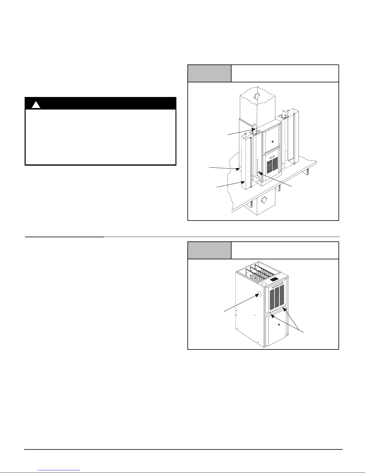
Pressure Switch Relocation
If the furnace is installed in the upflow position, the pressure switch
will remain in the same position as installed by the factory unless
the inducer is rotated. If the furnace is installed in an orientation
that places the pressure switch below the pressure tap on the
inducer housing, then the switch MUST be relocated. In order to
relocate the switch, locate 2 mounting holes or drill above the
inducer pressure tap. When drilling the 2 holes make sure to keep
the switch and tubing far enough away from the burners or hot
surfaces as to not melt the hose, switch, or wires. To prevent
possible kinking of the pressure switch hose, trim the hose to
remove excess length.
Note: When drilling new holes make sure metal shavings do not fall
on or in components, as this can shorten the life of the furnace.
See side venting
for venter rotation
Typical Downflow Installation
Figure 5
VENT
GAS SUPPLY
MUST BE OPPOSITE
VENT DISCHARGE
SIDE
SUPPLY
AIR
RETURN
AIR
OPTIONAL VENT
25!23!19
Combustible floor
base outlet flange
adapter
Vent Shield
Kit
3. Side Venting
This furnace is shipped from the factory with the venter assembly
in an upflow configurations (top vent). The venter assembly can
easily be rotated to a side vent configuration for use in upflow,
horizontal!flow, or downflow application.
When using a side vent configuration (side outlet instead of top
outlet), it may be necessary to relocate the pressure switch to the
alternate position on the opposite side of the top panel. Two screw
holes are provided at the alternate position. Route the pressure
switch tubing so the tubing is not kinked and not touching the hot
collector box, venter housing, or motor. It may be necessary to
shorten the length of the tubing to properly route the tubing and
eliminate kinks.
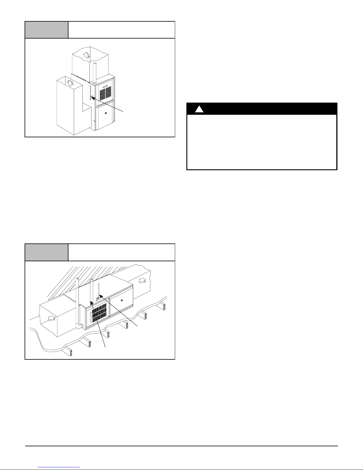
Rotating the Venter Assembly
1. If gas and electrical power have already been connected to
unit shut off gas and remove power from unit. Unscrew screws
on burner compartment door and remove burner compartment
door. (see Figure 6).
2. Disconnect power leads to the venter motor and hose to
pressure switch. Remove three (3) or four (4) screws which
secure the venter to the collector box, (see Figure 7).
3. Cut webbing with a pair of snips holding the vent plate to the
cabinet on either the left or right side of unit depending on right
or left venting as desired. Discard vent plate, (see Figure 6).
4. Replace venter gasket (part # 1013540, if needed) to venter
assembly with adhesive in the same location as the old one.
5. Clip the wire tie for the venter wires, if needed.
6. Rotate venter assembly 90° right or left from original location
depending on venting configurations.
Figure 6
25!23!45
Screws (2)
Furnace with Screws
Vent Plate
National Excelsior Company
www.excelsiorhvac.com
Subject to change without notice.
441 01 2613 05
9
Specifications are subject to change without notice
Figure 7
Venter Gasket
25-23-52b
Entry
25-23-52c
Main Line
7. Tighten the three (3) or four (4) screws that secure the venter
assembly to the collector box. Do tighten screws enough to
compress venter gasket.
8. Replace power leads to venter motor and reconnect hose to
pressure switch.
NOTE: Unused open vent hole must be covered. A Vent Cover is
supplied with Vent Pipe Shield Kit NAHA002VC. A 5
5
/16″ (135mm)
diameter Vent Cover is available separately from your distributor,
or one can be fabricated with sheet metal for all side vent
installations.
4. Combustion & Ventilation Air
CARBON MONOXIDE POISONING HAZARD
Failure to follow this warning could result in
personal injury or death.
Use methods described here to provide
combustion and ventilation air.
!
WARNING
Furnaces require ventilation openings to provide sufficient air for
proper combustion and ventilation of flue gases. All duct or
openings for supplying combustion and ventilation air must
comply with the gas codes, or in the absence of local codes, the
applicable national codes.
Combustion and ventilation air must be supplied in accordance
with one of the following:
Note: The Combustion & Ventilation Air Section, in this document,
uses tables and information from the ANSI Z223.1/NFPA
54!2009. For use in Canada, use CSA B149.1 for this
information.
1. Section 9.3, Air for Combustion and Ventilation, of the National
Fuel Gas Code, (NFGC), ANSI Z223.1/NFPA 54!2009 in the
U.S.,
2. Sections 8.2, 8.3, 8.5, 8.6, 8.7, and 8.8 of National Standard of
Canada, Natural Gas and Propane Installation Code
(NSCNGPIC), CSA B149.1!05 in Canada,
3. Applicable provisions of the local building code.
When the installation is complete, check that all appliances have
adequate combustion air and are venting properly. See Venting
And Combustion Air Check in “Gas Vent Installation” Section in
this manual.
Contaminated Combustion Air
Installations in certain areas or types of structures could cause
excessive exposure to contaminated air having chemicals or
halogens that will result in safety and performance related
problems and may harm the furnace. These instances must use
only outdoor air for combustion.
The following areas or types of structures may contain or have
exposure to the substances listed below. The installation must be
evaluated carefully as it may be necessary to provide outdoor air
for combustion.
• Commercial buildings.
• Buildings with indoor pools.
• Furnaces installed in laundry rooms.
• Furnaces installed in hobby or craft rooms.
• Furnaces installed near chemical storage areas.
• Permanent wave solutions for hair.
• Chlorinated waxes and cleaners.
• Chlorine based swimming pool chemicals.
• Water softening chemicals.
• De!icing salts or chemicals.
• Carbon tetrachloride.
• Halogen type refrigerants.
• Cleaning solvents (such as perchloroethylene).
• Printing inks, paint removers, varnishes, etc.
• Hydrochloric acid.
• Sulfuric Acid.
• Solvent cements and glues.
• Antistatic fabric softeners for clothes dryers.
• Masonry acid washing materials.
Outdoor Combustion Air Method
A space having less than 50 cubic feet per 1,000 BTUH (4.8 cubic
meters per kW) input rating for all gas appliances installed in the
space requires outdoor air for combustion and ventilation.
Air Openings and Connecting Ducts
1. Total input rating for all gas appliances in the space MUST be
considered when determining free area of openings.
2. Connect ducts or openings directly to the outdoors.
3. When screens are used to cover openings, the openings
MUST be no smaller than
1
/4″ (6.4mm) mesh.
4. The minimum dimension of air ducts MUST NOT be less than
3″(76.2mm).
5. When sizing a grille, louver or screen use the free area of
opening. If free area is NOT stamped or marked on grill or
louver, assume a 20% free area for wood and 60% for metal.
Screens shall have a mesh size not smaller than
1
/4″(6.4mm).
Requirements
1. Provide the space with sufficient air for proper combustion and
ventilation of flue gases using horizontal or vertical ducts or
openings.
National Excelsior Company
www.excelsiorhvac.com
Subject to change without notice.
10
441 01 2613 05
Specifications are subject to change without notice
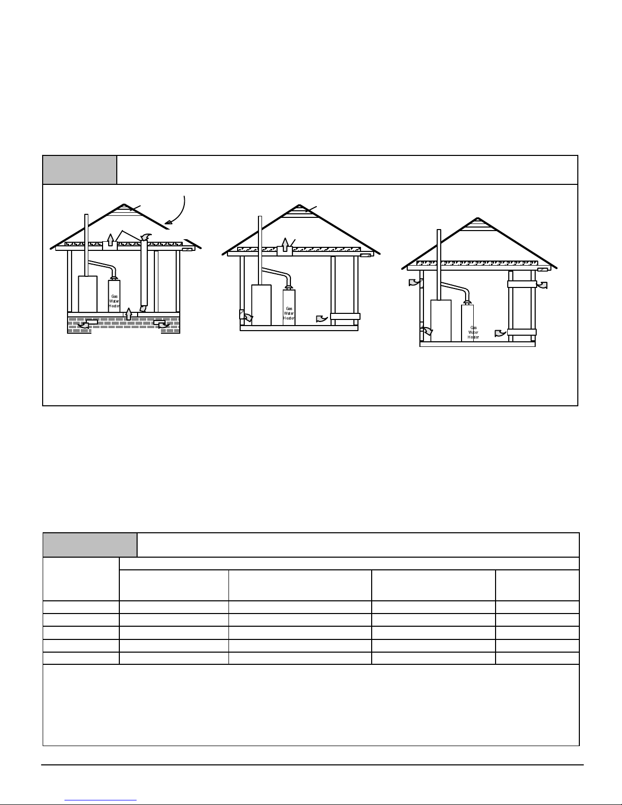
2. Figure 8 illustrates how to provide combustion and ventilation
air when two permanent openings, one inlet and one outlet, are
used.
a. One opening MUST commence within 12″ (304.8mm) of
the floor and the second opening MUST commence
within 12″ (304.8mm) of the ceiling.
b. Size openings and ducts per Table 1.
c. Horizontal duct openings require 1 square inch of free
area per 2,000 BTUH (11 cm
2
/kW) of combined input for
all gas appliances in the space (see Table 1).
d. Vertical duct openings or openings directly
communicating with the outdoors require 1 square inch
of free area per 4,000 BTUH (5.5 cm
2
/kW) for combined
input of all gas appliances in the space (see Table 1).
3. When one permanent outdoor opening is used, the opening
requires:
a. 1 sq. in of free area per 3,000 BTUH (7 cm
2
/kW) for
combined input of all gas appliances in the space (see
Table 1) and
b. Not less than the sum of the areas of all vent connectors
in the space.
Figure 8
Furnace
Furnace
Minimum One Inlet and One Outlet Air Supply is Required
May be in and Combination Shown
Inlet Air Opening Must be Within12″(304.8 mm) of floor
Outlet Air Opening Must be Within12″(304.8 mm) of ceiling
(1) 1 Square Inch per 4000 BTUH
(2) 1 Square Inch per 2000 BTUH
Outside Air (This is ONLY a guide. Subject to codes of country having jurisdiction.)
This installation NOT approved in Canada
Gas Vent
Gas Vent
Gas Vent
Gable Vent
Gable Vent
Outlet
Air (1)
Outlet Air (1)
Outlet Air (1)
Furnace
Outlet
Air (2)
Optional Inlet Air (1)
Ventilated Attic
Ventilated Attic
Ventilated Crawl Space
Inlet
Air (1)
Inlet
Air (1)
Inlet
Air (1)
Inlet
Air (2)
Inlet
Air (2)
Top Above Insulation
Top Above Insulation
Soffit Vent
Soffit Vent
The opening shall commence within 12″ (304.8mm) of the top of
the enclosure. Appliances shall have clearances of at least 1″
(25.4mm) from the sides and back and 6″ (152.4mm) from the
front. The opening shall directly communicate with the outdoors or
shall communicate through a vertical or horizontal duct to the
outdoors or spaces (crawl or attic) that freely communicate with
the outdoors.
4. Combination of Indoor and Outdoor Air shall have:
a. Indoor openings that comply with the Indoor
Combustion Air Method below and
b. Outdoor openings located as required in the Outdoor
Combustion Air Method above and
c. Outdoor openings sized as follows.
1) Calculate the Ratio of all Indoor Space volume
divided by required volume for Indoor Combustion Air
Method. Outdoor openings sized as follows.
2) Outdoor opening size reduction Factor is 1 minus the
Ratio in 1) above.
3) Minimum size of Outdoor openings shall be the size
required in Outdoor Combustion Air Method above
multiplied by reduction Factor.
Table 1
Free Area
BTUH (kW)
Input
Rating
Minimum Free Area Required for Each Opening or Duct to Outdoors
Two Horizontal Ducts
BTUH (kW)
sq. in./2,000(1 cm
2
/.09)
Single Opening
BTUH (kW)
sq. in./3,000 (1 cm
2
/.135)
Two Vertical Ducts or Openings
BTUH (kW)
sq. in./4,000(1 cm
2
/.18)
Round Duct
BTUH (kW)
sq. in./4,000(6.5cm
2
/.18)
50,000 (14.65) 25 sq. in. (161 cm2) 16.7 sq. in. (108 cm2) 12.5 sq. in. (81 cm2) 4″ (101.6mm)
75,000 (21.98) 37.5 sq. in. (242 cm2) 25 sq. in. (161 cm2) 18.75 sq. in. (121 cm2) 5″ (127mm)
100,000 (29.31) 50 sq. in. (322 cm2) 33.3 sq. in. (215 cm2) 25 sq. in. (161 cm2) 6″ (152.4mm)
125,000 (36.63) 62.50 sq. in. (403 cm2) 41.7 sq. in. (269 cm2) 31.25 sq. in. (202 cm2) 7″ (177.8mm)
150,000 (43.95) 75 sq. in. (484 cm2) 50 sq. in. (322 cm2) 37.5 sq. in. (242 cm2) 7″ (177.8mm)
EXAMPLE: Determining Free Area
Furnace
100,000
29.31
Furnace
100,000
29.31
+
+
Water Heater
30,000
8.8
Water Heater
30,000
8.8
=
=
Total Input
(130,000 ÷ 4,000)
(38.11 ÷ .18)
Total Input
(130,000 ÷ 2,000)
(38.11 ÷ .09)
= 32.5 Sq. In. Vertical
= 210 c
m
2
Vertical
= 65 Sq. In. Horizontal
= 423
cm
2
Horizontal
National Excelsior Company
www.excelsiorhvac.com
Subject to change without notice.
441 01 2613 05
11
Specifications are subject to change without notice
Indoor Combustion Air
Standard and Known-Air-Infiltration Rate Methods
NFPA & AGA
Indoor air is permitted for combustion and ventilation, if the
Standard or Known!Air!Infiltration Rate Method is used.
!
CARBON MONOXIDE POISONING HAZARD
Failure to follow this warning could result in
personal injury or death.
Most homes will require additional air from outdoors
for combustion and ventilation. A space with at least
50 cubic feet per 1,000 BTUH (1.4 cubic meters per
.293 kW/h) input rating or homes with tight
construction may need outdoor air to supplement air
infiltration for proper combustion and ventilation of
flue gases.
WARNING
The Standard Method may be used, if the space has no less
volume than 50 cubic feet per 1,000 BTUH (4.8 cubic meters per
kW) of the maximum input ratings for all gas appliances installed in
the space. The standard method permits indoor air to be used for
combustion and ventilation air.
The Known Air Infiltration Rate Method shall be used if the
infiltration rate is known to be less than 0.40 air changes per hour
(ACH) and equal to or greater than 0.10 ACH. Infiltration rates
greater than 0.60 ACH shall not be used. The minimum required
volume of the space varies with the number of ACH and shall be
determined per Table 2 or Equations 1 and 2. Determine the
minimum required volume for each appliance in the space, and
add the volumes together to get the total minimum required
volume for the space.
Table 2
MINIMUM SPACE VOLUME FOR 100% COMBUSTION AND VENTILATION AIR FROM INDOORS
Other Than Fan-Assisted Total Fan-assisted Total
ACH
30,000 BTU
(8.79 kW)
40,000 BTU
(11.72 kW)
50,000 BTU
(14.65 kW)
50,000 BTU
(14.65 kW)
75,000
(21.98 kW)
100,000 BTU
(29.30 kW)
125,000 BTU
(36.63 kW)
150,000 BTU
(43.95 kW)
ft
3
(m3)
0.60 1,050 (29.7) 1,400 (39.2) 1,750 (49) 1,250 (35) 1,875 (52.5) 2,500 (70) 3,125 (87.5) 3,750 (105)
0.50 1,260 (35.3) 1,680 (47.04) 2,100 (58.8) 1,500 (42) 2,250 (63) 3,000 (84) 3,750 (105) 4,500 (126)
0.40 1,575 (44.1) 2,100 (58.8) 2,625 (73.5) 1,875 (52.5) 2,813 (78.8) 3,750 (105) 4,688 (131.3) 5,625 (158)
0.30 2,100 (58.8) 2,800 (78.4) 3,500 (98) 2,500 (70) 3,750 (105) 5,000 (140) 6,250 (175) 7,500 (210.6)
0.20 3,150 (88.2) 4,200 (117.6) 5,250 (147) 3,750 (105) 5,625 (157.5) 7,500 (210) 9,375 (262.5) 11,250 (316)
0.10 6,300 (176.4) 8,400 (235.2) 10,500 (294) 7,500 (210) 11,250 (315) 15,000 (420) 18,750 (525) 22,500 (632)
0.00 NP NP NP NP NP NP NP NP
NP = Not Permitted
Table 2 Minimum Space Volumes were determined by using the
following equations from the National Fuel Gas Code ANSI
Z223.1/NFPA 54!2009, 9.3.2.2:
1. For other than fan!assisted appliances such as a draft
hood!equipped water heater,
1000 Btu / hr
21 ft
3
(
I
other
)
Volume
other
=
ACH
.293 kW / hr
59 m
3
(
I
other
)
Required Volume
other
!
ACH
2. For fan!assisted appliances such as this furnace,
1000 Btu / hr
15 ft
3
(
I
fan
)
Volume
fan
=
ACH
.293 kW / hr
.42 m
3
(
I
fan
)
Required Volume
fan
!
ACH
If:
I
other
= combined input of all other than fan!assisted
appliances in Btu/hr
I
fan
= combined input of all fan!assisted appliances in Btu/hr
ACH = air changes per hour (ACH shall not exceed 0.60.)
The following requirements apply to the Standard Method and to
the Known Air Infiltration Rate Method.
• Adjoining rooms can be considered part of a space, if there
are no closable doors between rooms.
• An attic or crawl space may be considered a space that freely
communicates with the outdoors provided there are adequate
ventilation openings directly to outdoors. Openings MUST
remain open and NOT have any means of being closed off.
Ventilation openings to outdoors MUST be at least 1 square
inch of free area per 4,000 BTUH (5.5 cm
2
/kW) of total input
rating for all gas appliances in the space.
• In spaces that use the Indoor Combustion Air Method,
infiltration should be adequate to provide air for combustion,
ventilation and dilution of flue gases. However, in buildings
with unusually tight construction, additional air MUST be
provided using the methods described in section titled
Outdoor Combustion Air Method:
• Unusually tight construction is defined as Construction with:
1. Walls and ceilings exposed to the outdoors have a
continuous, sealed vapor barrier. Openings are gasketed
or sealed and
2. Doors and openable windows are weather stripped and
3. Other openings are caulked or sealed. These include
joints around window and door frames, between sole
plates and floors, between wall!ceiling joints, between
wall panels, at penetrations for plumbing, electrical and
gas lines, etc.
Ventilation Air
Some provincial codes and local municipalities require ventilation
or make!up air be brought into the conditioned space as
National Excelsior Company
www.excelsiorhvac.com
Subject to change without notice.

12
441 01 2613 05
Specifications are subject to change without notice
replacement air. Whichever method is used, the mixed return air
temperature across the heat exchanger MUST not fall below 60°
F(16° C) continuously, or 55° F(13° C) on an intermittent basis so
that flue gases will not condense excessively in the heat
exchanger. Excessive condensation will shorten the life of the heat
exchanger and possibly void your warranty.
5. Gas Vent Installation
CARBON MONOXIDE POISONING, FIRE AND
EXPLOSION HAZARD
Failure to follow this warning could result in
personal injury, death, and/or property damage.
Read and follow all instructions in this section.
!
WARNING
Install the vent in compliance with codes of the country having
jurisdiction, local codes or ordinances and these instructions.
This Category I furnace is fan!assisted.
Category I furnace definition: A central furnace which operates
with a non!positive vent static pressure and with a flue loss not
less than 17 percent. These furnaces are approved for
common!venting and multi!story venting with other fan!assisted
or draft hood!equipped appliances in accordance with the NFGC
or NSCNGPIC
Category I Safe Venting Requirements
Category I furnace vent installations shall be in accordance with
Parts 12 and 13 of the National Fuel Gas Code (NFGC), ANSI
Z223.1/NFPA 54!2009; and/or Section 8 and Appendix C of the
CSA B149.1!05, National Standard of Canada, Natural Gas and
Propane Installation Code; the local building codes; furnace and
vent manufacturer’s instructions.
NOTE: The following instructions comply with the ANSI
Z223.1/NFPA 54!2009 National Fuel Gas Code and CSA B149.1
Natural Gas and Propane Installation code, based on the input
rate on the furnace rating plate.
1. If a Category I vent passes through an attic, any concealed
space or floor, use ONLY Type B or Type L double wall vent
pipe. If vent pipe passes through interior wall, use Type B vent
pipe with ventilated thimble ONLY.
2. Do NOT vent furnace into any chimney serving an open
fireplace or solid fuel burning appliance.
3. Use the same diameter Category I connector or pipe as
permitted by:
• the National Fuel Gas Code Code ANSI Z223.1/ NFPA
54!2009 Sections 12 and 13 venting requirements in the
United States
or
• the National Standard of Canada Natural Gas and
Propane Installation Code (NSCNGPIC) CSA
B149.1!05 Section 8 and appendix C venting
requirements in Canada.
4. Push the vent connector onto the furnace flue collar of the
venter assembly until it touches the bead [at least
5
/8″
(15.9mm) overlap] and fasten with at least two field!supplied,
corrosion!resistant, sheet metal screws located at least 140°
apart.
5. Keep vertical Category I vent pipe or vent connector runs as
short and direct as possible.
6. Vertical outdoor runs of Type!B or ANY single wall vent pipe
below the roof line are NOT permitted.
7. Slope all horizontal runs up from furnace to the vent terminal a
minimum of
1
/4″ per foot (10mm/m).
8. Rigidly support all horizontal portions of the venting system
every 6′ or less using proper clamps and metal straps to
prevent sagging and ensure there is no movement after
installation.
9. Check existing gas vent or chimney to ensure they meet
clearances and local codes. See Figure 1
10. The furnace MUST be connected to a factory built chimney or
vent complying with a recognized standard, or a masonry or
concrete chimney lined with a lining material acceptable to the
authority having jurisdiction. Venting into an unlined
masonry chimney or concrete chimney is prohibited. See
the 6. Masonry Chimney Venting section in these
instructions.
11. Fan!assisted combustion system Category I furnaces shall
not be vented into single!wall metal vents.
12. Category I furnaces must be vented vertically or nearly
vertically, unless equipped with a listed mechanical venter.
13. Vent connectors serving Category I furnaces shall not be
connected into any portion of mechanical draft systems
operating under positive pressure.
Venting and Combustion Air Check
NOTE: When an existing Category I furnace is removed or
replaced, the original venting system may no longer be sized to
properly vent the attached appliances, and to make sure there is
adequate combustion air for all appliances, MAKE THE
FOLLOWING CHECK.
Vent Check
Draft HoodVent Pipe
Match
Typical Gas
Water Heater
Figure 9
NOTE: If flame pulls towards draft hood, this indicates
sufficient infiltration air.
National Excelsior Company
www.excelsiorhvac.com
Subject to change without notice.

441 01 2613 05
13
Specifications are subject to change without notice
CARBON MONOXIDE POISONING HAZARD
Failure to follow the steps outlined below for each
appliance connected to the venting system being placed
into operation, could result in carbon monoxide
poisoning or death:
The following steps shall be followed for each appliance
connected to the venting system being placed into
operation, while all other appliances connected to the
venting system are not in operation:
1.Seal any unused openings in the venting system.
2.Inspect the venting system for proper size and horizontal
pitch, as required in the National Fuel Gas Code, ANSI
Z223.1/NFPA 54 or CSA B149.1, Natural Gas and
Propane Installation Code and these instructions. Deter-
mine that there is no blockage or restriction, leakage, corrosion and other deficiencies which could cause an unsafe
condition.
3.As far as practical, close all building doors and windows
and all doors between the space in which the appliance(s)
connected to the venting system are located and other
spaces of the building.
4.Close fireplace dampers.
5.Turn on clothes dryers and any appliance not connected to
the venting system. Turn on any exhaust fans, such as
range hoods and bathroom exhausts, so they are
operating at maximum speed. Do not operate a summer
exhaust fan.
6.Follow the lighting instructions. Place the appliance being
inspected into operation. Adjust the thermostat so
appliance is operating continuously.
7.Test for spillage from draft hood equipped appliances at
the draft hood relief opening after 5 minutes of main burner
operation. Use the flame of a match or candle. (Figure 9)
8.If improper venting is observed, during any of the above
tests, the venting system must be corrected in accordance
with the National Fuel Gas Code, ANSI Z223.1/NFPA 54
and/or CSA B149.1, Natural Gas and Propane Installation
Code.
9.After it has been determined that each appliance connected to the venting system properly vents when tested
as outlined above, return doors, windows, exhaust fans,
fireplace dampers and any other gas!fired burning
appliance to their previous conditions of use.
!
WARNING
Venting to Existing Masonry Chimney
Dedicated venting of one fan assisted furnace into any
masonry chimney is restricted. A chimney must first be lined
with either Type B vent sized in accordance with
ANSIZ223.1/NFPA!2009 tables 13.1a or 13.1b or a listed metal
lining system. (See Masonry Chimney Venting of these
instructions.)
Listed, corrugated metallic chimney liner systems in masonry
chimneys shall be sized by using ANSIZ223.1/NFPA!2009
section 13.1.7 for dedicated venting and 13.2.20 for common
venting with the maximum capacity reduced by 20% (0.80 X
maximum capacity) and the minimum capacity as shown in the
applicable table. In Canada, use the CSA B149.1!05 Natural Gas
and Propane Installation Code, appendix C, Section 10.
Corrugated metal vent systems installed with bends or offsets
require additional reduction of 5% of the vent capacity for each
bend up to 45° and 10% of the vent capacity for each bend from 45°
up to 90°.
NOTE: Two (2) 45° elbows are equivalent to one (1) 90° elbow.
Combined Venting into a Masonry Chimney
Venting into a masonry or concrete chimney is only permitted
as outlined in the NFGC or NSCNGPIC venting tables. Follow
all safe venting requirements.
Note: See section “Masonry Chimney Venting”.
6. Horizontal Venting
Category I Furnaces With External Power
Venters
In order to maintain a Category I classification of fan!assisted
furnaces when vented horizontally with sidewall termination, a
power venter is REQUIRED to maintain a negative pressure in the
venting system.
In the U.S.: Per the NFGC, a listed power venter may be used,
when approved by the authority having jurisdiction.
In Canada: Only power venters approved by the power venter
manufacturer and where allowed by the authority having
jurisdiction may be used.
Please consult the Fields Controls Co. or Tjernlund Products, Inc.
for power venters certified for use with our furnaces.
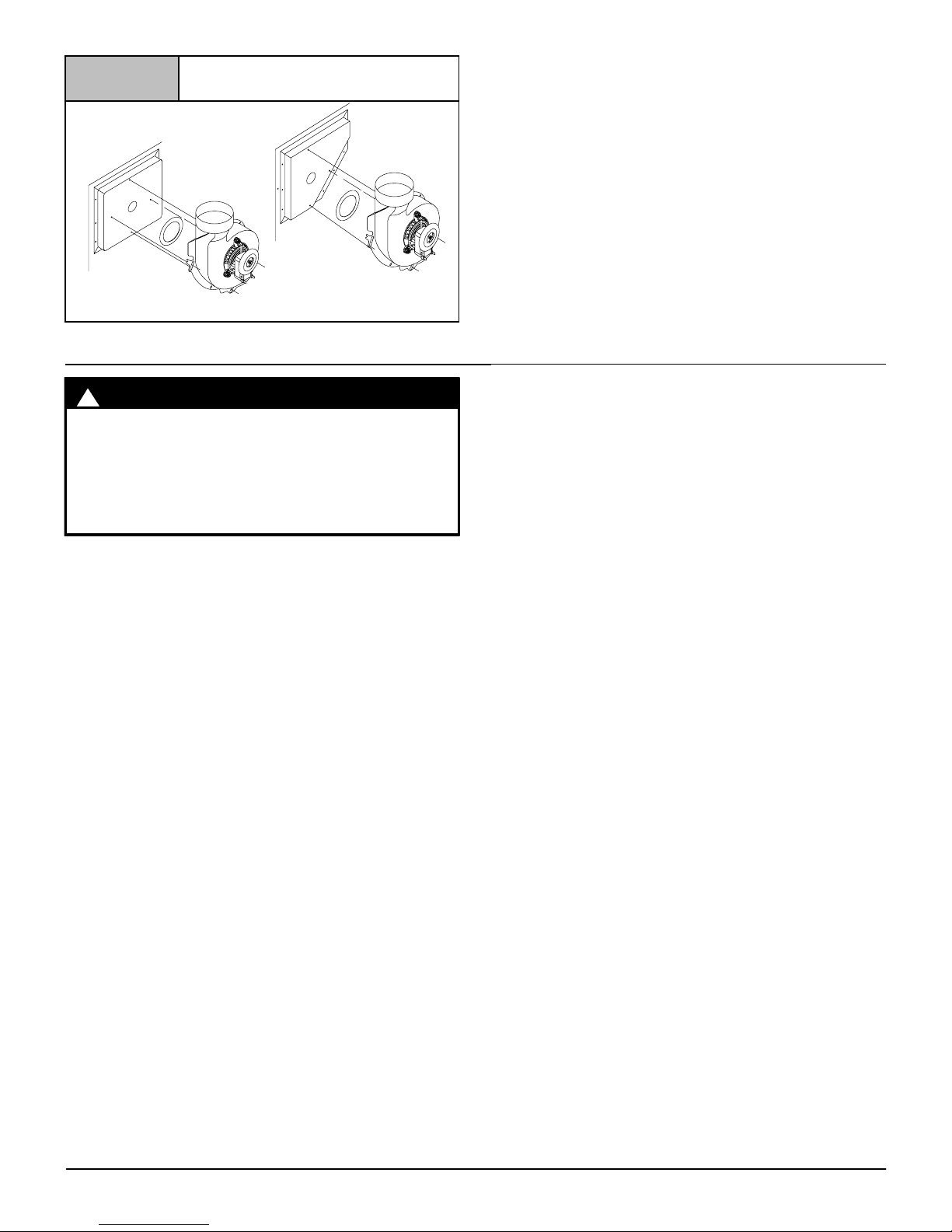
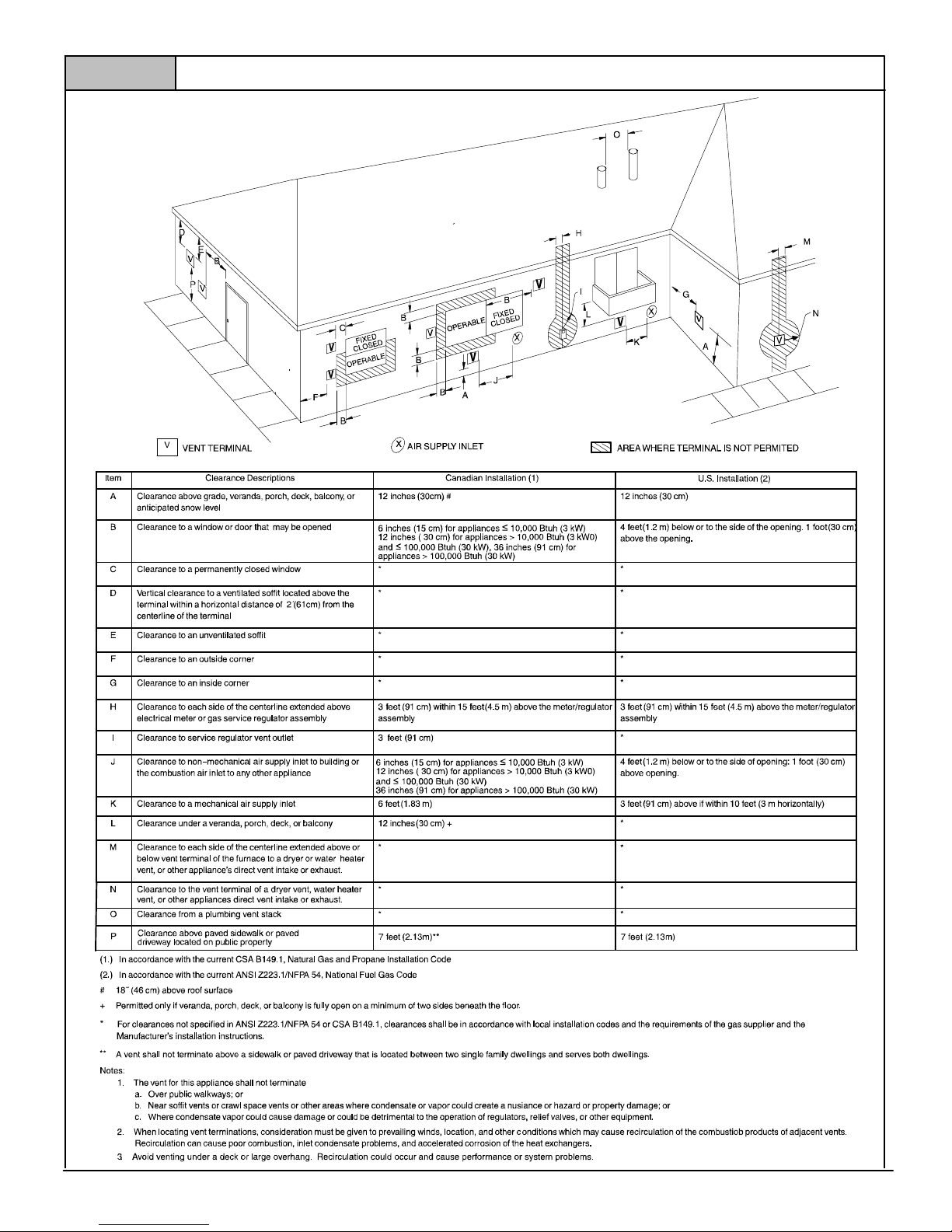
Vent Termination
Venting Through a Non-Combustible and
Combustible Wall
Consult External Power Venter manufacturer instructions.
Select the power venter to match the Btuh input of the furnace
being vented. Follow all of the Power Venter manufacturer’s
installation requirements included with the power venter for:
• venting installation,
• vent terminal location,
• preventing blockage by snow,
• protecting building materials from degradation by flue gases,
• see Figure 10 for required vent termination.
NOTE: It is the responsibility of the installer to properly terminate
the vent and provide adequate shielding. This is essential in order
to avoid water/ice damage to building, shrubs and walkways.
National Excelsior Company
www.excelsiorhvac.com
Subject to change without notice.
Other than Direct Vent Termination Clearance
Figure 10
A05013
V
V
14
441 01 2613 05
Specifications are subject to change without notice
National Excelsior Company
www.excelsiorhvac.com
Subject to change without notice.

441 01 2613 05
15
Specifications are subject to change without notice
7. Masonry Chimney Venting
Chimney Inspection
All masonry chimney construction must conform to Standard
ANSI/NFPA 211!2006 and to any state or local codes applicable.
The chimney must be in good condition and a complete chimney
inspection must be conducted prior to furnace installation. If the
inspection reveals damage or abnormal conditions, make
necessary repairs or seek expert help. See Figure 11 “The
Chimney Inspection Chart”. Measure inside area of tile!liner and
exact height of chimney from the top of the chimney to the highest
appliance flue collar or drafthood outlet.
Connector Type
To reduce flue gas heat loss and the chance of condensate
problems, the vent connector must be double!wall Type B vent.
Venting Restrictions for Chimney Types
Interior Chimney ! has no sides exposed to the outdoors below
the roofline. All installations can be single furnace or common
vented with another draft hood equipped Category I appliance.
Exterior Chimney ! has one or more sides exposed to the
outdoors below the roof line. All installations with a 99% Winter
Design Temperature* below 17°F(!8°C) must be common vented
only with a draft hood equipped Category I appliance.
* The 99% Winter Design Dry!Bulb (db) temperatures are
found in the 2005 ASHRAE Fundamentals Handbook CD
and Chapter 28.
CARBON MONOXIDE POISONING, FIRE AND
EXPLOSION HAZARD
Failure to follow this warning could result in
personal injury, death, and/or property damage.
These furnaces are CSA (formerly AGA and CGA)
design!certified for venting into exterior clay
tile!lined masonry chimneys with a factory
accessory Chimney Adapter Kit. Refer to the
furnace rating plate for correct kit usage. The
Chimney Adapter Kits are for use with ONLY
furnaces having a Chimney Adapter Kit number
marked on the furnace rating plate.
!
WARNING
If a clay tile!lined masonry chimney is being used and it is exposed
to the outdoors below the roof line, relining might be required.
Chimneys shall conform to the Standard for Chimneys,
Fireplaces, Vents, and Solid Fuel Burning Appliances ANSI/NFPA
211!2006 in the United States and to a Provincial or Territorial
Building Code in Canada (in its absence, the National Building
Code of Canada) and must be in good condition.
U.S.A.!Refer to Sections 13.1.9 or 13.2.22 of the ANSI
Z223.1/NFPA 54!2009 or the authority having jurisdiction to
determine whether relining is required. If relining is required, use a
properly sized listed metal liner, Type!B vent, or a listed alternative
venting design.
NOTE: See the ANSI Z223.1/NFPA 54!2009, 13.1.9 and 13.2.22
regarding alternative venting design and the exception, which
cover installations such as the Chimney Adapter Kits
NAHA001DH and NAHA002DH.
The Chimney Adapter Kits are listed alternative venting designs
for these furnaces. See the kit instructions for complete details.
Canada (and U.S.A.)!This furnace is permitted to be vented into a
clay tile!lined masonry chimney that is exposed to the outdoors
below the roof line, provided:
1. Vent connector is Type!B double!wall, and
2. This furnace is common vented with at least 1 draft
hood!equipped appliance, and
3. The combined appliance input rating is less than the
maximum capacity given in Table A, and
4. The input rating of each space!heating appliance is greater
than the minimum input rating given in Table B for Masonry
Chimneys for the local 99% Winter Design Temperature.
Chimneys having internal areas greater than 38 square
inches (245 sq. cm) require furnace input ratings greater
than the input ratings of these furnaces. See footnote at
bottom of Table B, and
5. The authority having jurisdiction approves.
If all of these conditions cannot be met, an alternative venting
design shall be used, such as the listed chimney adapter kit with a
furnace listed for use with the kit, a listed chimney!lining system,
or a Type!B vent.
These furnaces are CSA design!certified for use in exterior clay
tile!lined masonry chimneys with a factory accessory Chimney
Adapter Kit. Refer to the furnace rating plate for correct kit usage.
The Chimney Adapter Kits are listed alternative venting designs
and are for use with ONLY furnaces having a Chimney Adapter Kit
number marked on the furnace rating plate.
National Excelsior Company
www.excelsiorhvac.com
Subject to change without notice.

16
441 01 2613 05
Specifications are subject to change without notice
Chimney is
acceptable for use
Crown
condition:
Missing mortar
or brick?
Rebuild
crown
Is
Chimney properly lined
with clay tile
liner?
Yes
Yes
No
No
Yes
Is
liner and top
seal in good
condition
No
Debris in
cleanout? Mortar, tile,
metal vent, fuel oil
residue?
Repair
liner or top seal
or reline chimney as
necessary.
Reline
Yes Repair
Yes
No
Yes
Clay
tile misalignment,
missing sections,
gaps?
No
Is Chimney
lined with properly
sized, listed liner or
Type-B vent?
Line chimney with properly
sized, listed flexible metal
liner or Type-B vent per NFGC or
NSCNGPIC Vent Sizing Tables
and liner or vent manufacturer's
installation instructions.
CHIMNEY INSPECTION CHART
For additional requirements refer to the National Fuel Gas Code ANSI Z223.1/NFPA 54-2009 and ANSI/NFPA 211-2006 Chimneys, Fireplaces, Vents, and Solid Fuel
Burning Appliances in the U.S.A. or to the Canadian Installation Code CSA B149.1-05 in Canada.
Yes
No
No
Mortar or
tile debris?
Yes
Remove mortar
and tile debris?
No
Remove metal vent or liner.
Consult
Part B of chimney
adapter venting
instructions for
application
suitability.
Chimney
exposed to outdoors
below roof line?
Is Chimney to
be dedicated to a
single furnace?
Yes
Install chimney
adapter per
instructions.
Not Suitable
Not Suitable
Suitable
No
Consult
Part C of chimney
adapter venting
instructions for
application
suitability.
Suitable
Install chimney
adapter per
instructions.
No
Condensate
drainage at bottom
of chimney?
Yes
Figure 11
National Excelsior Company
www.excelsiorhvac.com
Subject to change without notice.
441 01 2613 05
17
Specifications are subject to change without notice
Exterior Masonry Chimney,
FAN+NAT Installations with
Type!B Double!Wall Vent Connectors
! NFPA & AGA
Table A-
Combined Appliance
Maximum Input Rating in
Thousands of Btu per Hr
VENT
HEIGHT
FT(m)
INTERNAL AREA OF CHIMNEY
SQ IN.(cm)
12(77.4) 19(122.6) 28(180.6) 38(245.2)
6(1.8) 74 119 178 257
8(2.4) 80 130 193 279
10(3) 84 138 207 299
15(4.6) NR 152 233 334
20(6.1) NR NR 250 368
30(9.1) NR NR NR 404
Table B-
Minimum Allowable Input Rating of
Space-Heating Appliance in
Thousands of Btu per Hr
VENT
HEIGHT
FT(m)
INTERNAL AREA OF CHIMNEY
sq. in(cm)
12(77.4) 19(122.6) 28(180.6) 38(245.2)
17 to 26"F (!8 to !3"C)
Local 99% Winter Design Temperature:
17 to 26°F (!8 to !3°C)*
6(1.8) 0 55 99 141
8(2.4) 52 74 111 154
10(3) NR 90 125 169
15(4.6) NR NR 167 212
20(6.11) NR NR 212 258
30(9.1) NR NR NR 362
5 t o 16"F (!15 to !9"C)
Local 99% Winter Design Temperature:
5 to 16°F (!15 to !9°C)*
6(1.8) NR 78 121 166
8(2.4) NR 94 135 182
10(3) NR 111 149 198
15(4.6) NR NR 193 247
20(6.11) NR NR NR 293
30(9.1) NR NR NR 377
!10 to 4"F (!23 to !16"C)
Local 99% Winter Design Temperature:
!10 to 4°F (!23 to !16°C)*
6(1.8) NR NR 145 196
8(2.4) NR NR 159 213
10(3) NR NR 175 231
15(4.6) NR NR NR 283
20(6.11) NR NR NR 333
30(9.1) NR NR NR NR
!11 °F
(!24°C)
or lower
Local 99% Winter Design Temperature:
!11°F (!24°C) or lower*
Not recommended for any vent configuration
* The 99% Winter Design Dry!Bulb (db) temperatures are
found in the 2005 ASHRAE Fundamentals Handbook CD
and Chapter 28.
Inspections before the sale and at the time of installation will
determine the acceptability of the chimney or the need for repair
and/or (re)lining. Refer to the Chimney Inspection Chart to
perform a chimney inspection.
If the inspection of a previously used tile!lined chimney:
a. Shows signs of vent gas condensation, the chimney should
be relined in accordance with local codes and the authority
having jurisdiction. The chimney should be relined with a
listed metal liner, Type!B vent, or a listed chimney adapter
kit to reduce condensation. If a condensate drain is required
by local code, refer to the ANSI Z223.1/NFPA 54!2009,
Section 12.10 for additional information on condensate
drains.
b. Indicates the chimney exceeds the maximum permissible
size in the tables, the chimney should be rebuilt or relined to
conform to the requirements of the equipment being
installed and the authority having jurisdiction.
A chimney without a clay tile liner, which is otherwise in good
condition, shall be rebuilt to conform to ANSI/NFPA 211!2006 or
be lined with a UL listed (ULC listed in Canada) metal liner or UL
listed Type!B vent. Relining with a listed metal liner or Type!B
vent is considered to be a vent!in!a!chase.
If a metal liner or Type!B vent is used to line a chimney, no other
appliance shall be vented into the annular space between the
chimney and the metal liner.
APPLIANCE APPLICATION REQUIREMENTS
Appliance operation has a significant impact on the performance
of the venting system. If the appliances are sized, installed,
adjusted, and operated properly, the venting system and/or the
appliances should not suffer from condensation and corrosion.
The venting system and all appliances shall be installed in
accordance with applicable listings, standards, and codes.
The furnace should be sized to provide 100 percent of the design
heating load requirement plus any margin that occurs because of
furnace model size capacity increments. Heating load estimates
can be made using approved methods available from Air
Conditioning Contractors of America (Manual J); American
Society of Heating, Refrigerating, and Air!Conditioning
Engineers; or other approved engineering methods. Excessive
oversizing of the furnace could cause the furnace and/or vent to
fail prematurely.
When a metal vent or metal liner is used, the vent or liner must be in
good condition and be installed in accordance with the vent or liner
manufacturer’s instructions.
To prevent condensation in the furnace and vent system, the
following precautions must be observed:
1. The return!air temperature must be at least 60°F(16°C) db
except for brief periods of time during warm!up from
setback at no lower than 55°F(13°C) db or during initial
start!up from a standby condition.
2. Adjust the gas input rate per the installation instructions.
Low gas input rate causes low vent gas temperatures,
causing condensation and corrosion in the furnace and/or
venting system. Derating is permitted only for altitudes
above 2000′ (610m).
3. Adjust the air temperature rise to the midpoint of the rise
range or slightly above. Low air temperature rise can cause
low vent gas temperature and potential for condensation
problems.
4. Set the thermostat heat anticipator or cycle rate to reduce
short cycling.
Air for combustion must not be contaminated by halogen
compounds which include chlorides, fluorides, bromides, and
iodides. These compounds are found in many common home
products such as detergent, paint, glue, aerosol spray, bleach,
cleaning solvent, salt, and air freshener, and can cause corrosion
of furnaces and vents. Avoid using such products in the
combustion!air supply. Furnace use during construction of the
building could cause the furnace to be exposed to halogen
compounds, causing premature failure of the furnace or venting
system due to corrosion.
National Excelsior Company
www.excelsiorhvac.com
Subject to change without notice.

18
441 01 2613 05
Specifications are subject to change without notice
Vent dampers on any appliance connected to the common vent
can cause condensation and corrosion in the venting system. Do
not use vent dampers on appliances common vented with this
furnace.
8. Gas Supply and Piping
CARBON MONOXIDE POISONING, FIRE AND
EXPLOSION HAZARD
Failure to follow this warning could result in
personal injury, death, and/or property damage.
Models designated for Natural Gas are to be used
with Natural Gas ONLY, unless properly converted to
use with Propane gas.
!
WARNING
Gas Supply Requirements
• Use only the type of gas approved for this furnace. See rating
plate for approved gas type.
• Gas input must not exceed the rated input shown on the rating
plate. Overfiring will result in failure of heat exchanger and
cause dangerous operation.
• Do not allow minimum supply pressure to vary downward.
Doing so will decrease input to furnace. Refer to Table 3 for
gas supply. Refer to Table 6 and Table 7 for manifold
pressures.
Table 3 Gas Pressures
Gas Type
Supply Pressure
Recommended Max. Min.
Natural 7 in wc
(1744 Pa)
14 in wc
(3487 Pa)
4.5 in wc
1121 Pa)
Propane 11 in wc
(2740 Pa)
14 in wc
(3487 Pa)
11 in wc
(2740 Pa)
Gas Piping Requirements
NOTE: The gas supply line must be installed by a qualified service
technician in accordance with all building codes.
NOTE: In the state of Massachusetts.
a. Gas supply connections MUST be performed by a
licensed plumber or gas fitter.
b. When flexible connectors are used, the maximum length
shall not exceed 36″ (914.4mm).
c. When lever handle type manual equipment shutoff
valves are used, they shall be T!handle valves.
d. The use of copper tubing for gas piping is NOT approved.
1. Install gas piping in accordance with local codes, or in the
absence of local codes, the applicable national codes.
2. It is recommended that a manual equipment shutoff valve be
installed in the gas supply line outside the furnace. Locate
valve as close to the furnace as possible where it is readily
accessible. Refer to Figure 12.
FIRE HAZARD
Failure to follow this warning could result in
personal injury or death.
Use wrench to hold furnace gas valve when turning
elbows and gas line to prevent damage to the gas
valve and furnace.
!
WARNING
O
N
O
F
F
O
N
O
F
F
Use elbows and 3# (76.2mm) pipe nipple to con
nect valve to piping when using right side gas
pipe entry.
* Union may be installed inside the cabinet when necessary because of clearances.
Drip Leg and Union, Union* should be outside the
cabinet. Manual shut-off valve MUST be upstream of
dripleg, union, and furnace.
Propane Low
pressure
switch.
25!24!86
3# (76.2mm)
pipe nipple
Manual shut-off
valve
Typical Gas Piping (N8MP)
Figure 12
Representative drawing only, some models may vary in appearance.
National Excelsior Company
www.excelsiorhvac.com
Subject to change without notice.

441 01 2613 05
19
Specifications are subject to change without notice
3. Use black iron or steel pipe and fittings or other pipe approved
by local code.
4. Use pipe thread compound which is resistant to natural and
Propane gases.
5. Use ground joint unions and install a drip leg no less than 3″
(76.2mm) long to trap dirt and moisture before it can enter gas
valve inside furnace.
6. Provide a
1
/8″ NPT plugged tapping for test gauge connection
immediately up stream of gas supply connection to furnace.
7. Use two pipe wrenches when making connections to prevent
furnace gas valve from turning.
NOTE: If local codes allow the use of a flexible gas appliance
connector, always use a new listed connector. Do not use a
connector which has previously served another gas appliance.
8. Flexible corrugated metal gas connector may NOT be used
inside the furnace or be secured or supported by the furnace
or ductwork.
9. Properly size gas pipe to handle combined appliance load or
run gas pipe directly from gas meter or Propane gas regulator.
10. Install correct pipe size for run length and furnace rating.
11. Measure pipe length from gas meter or Propane second
stage regulator to determine gas pipe size.
Right Side Gas Supply Piping (N8MP)
Gas line can be installed directly to the gas valve through the hole
provided in the right side of the cabinet. See Figure 12
Left Side Gas Supply Piping (N8MP)
Two(2) 90° street elbows or two(2) 90° standard elbows and
two(2) close nipples are required for left side gas supply. See
Figure 12.
Piping with Street Elbows
1. Assemble the elbows so that the outlet of one(1) elbow is 90°
from the inlet of the other. The elbows should be tight enough
to be leak proof. An additional
1
/
4
turn will be required at the
end of step 2, see Figure 13.
Figure 13
25!23!23c
Elbows (N8MP)
2. Screw elbow assembly into gas valve far enough to be leak
proof. Position elbow assembly so that the inlet of the elbow is
at the top of the gas valve. An additional
3
/8 turn will be
required in step 3. Turn open end of inlet elbow to face the left
side of the furnace (
1
/4 turn), see Figure 14.
Figure 14
Gas Valve with Elbows (N8MP)
Representative drawing only, some models may vary in appearance.
3. Turn assembly an additional 3/8 turn to position inlet near the
bottom back corner of the gas valve in line with gas opening
on left side of furnace, see Figure 15.
4. Gas supply line then can be run directly into opening of elbow.
Piping with Close Nipples and Standard Elbows
1. Assemble elbows and nipples similar to street elbows shown
in Figure 13.
2. Follow steps 2 through 4 Piping with Street Elbows.
Figure 15
Gas Valve with Elbows (N8MP)
Representative drawing only, some models may vary in appearance.
FIRE HAZARD
Failure to follow this warning could result in
personal injury, or death, and/or property damage.
Use wrench to hold furnace gas valve when turning
elbows and gas line to prevent damage to the gas
valve and furnace.
!
WARNING
Left Side Gas Entry (*8MP) (See Figure 16)
Pipe can be run directly to gas valve through the hole provided in
the left side of the cabinet.
Right Side Gas Entry (*8MP) (See Figure 16)
Two (2) 90° street elbows or two (2) 90° standard elbows and two
(2) close nipples are required for right side gas supply,.
National Excelsior Company
www.excelsiorhvac.com
Subject to change without notice.

20
441 01 2613 05
Specifications are subject to change without notice
Typical Gas Piping (*8MP)
Figure 16
25-25-02
Representative drawing only, some models may vary in appearance.
Piping with Street Elbows
1. Screw one elbow onto gas valve with the outlet facing away
from the furnace.
2. Screw second elbow onto first elbow tight enough to be leak
proof. An additional
1
/4 turn will be required at the end of step
2. See Figure 17 and Figure 18.
Figure 17
Gas Valve with Elbows (*8MP)
Representative drawing only, some models may vary in appearance.
Figure 18
Gas Valve with Elbows (*8MP)
Representative drawing only, some models may vary in appearance.
3. Gas supply line then can be run directly into opening of elbow.
Piping with Close Nipples and Standard Elbows
1. Assemble elbows and nipples similar to street elbows shown
in Figure 13.
2. Follow steps 2 through 4 Piping with Street Elbows.
FIRE OR EXPLOSION HAZARD
Failure to follow this warning could result in
personal injury, death and/or property damage.
A flexible corrugated metal gas connector must be
properly installed, shall not extend through the side
of the furnace, and shall not be used inside the
furnace.
Black iron pipe shall be installed at the furnace gas
valve and extend a minimum of 2# (50.8mm) outside
furnace.
!
WARNING
Additional Propane Piping Requirements
• Have a licensed Propane gas dealer make all connections at
storage tank and check all connections from tank to furnace.
• If copper tubing is used, it MUST comply with limitation set in
local codes, or in the absence of local codes, the gas codes of
the country having jurisdiction.
• Two!stage regulation of Propane gas is recommended.
FIRE OR EXPLOSION HAZARD
Failure to follow this warning could result in
personal injury, death and/or property damage.
An open flame or spark could result in death,
personal injury and/or property damage.
Propane gas is heavier than air and will settle and
remain in low areas and open depressions.
Thoroughly ventilate area and dissipate gas. Do
NOT use a match or open flame to test for leaks, or
attempt to start up furnace before thoroughly
ventilating area.
!
WARNING
Final Check
• Test all pipe for leaks.
• If orifices were changed, make sure they are checked for
leaks.
• During pressure testing of gas supply piping system:
a. If test pressure does not exceed
1
/2″ psig, isolate the
furnace from the gas supply piping system by closing the
equipment shutoff valve.
b. If test pressure exceeds
1
/2″ psig, the furnace and its
manual equipment shutoff valve must be disconnected from
the gas supply piping system.
• Use a commercially available soap solution made specifically
for the detection of leaks to check all connections..
• Do not use an open flame to test for gas leaks. Fire or
explosion could occur.
• Correct even the smallest leak at once.
National Excelsior Company
www.excelsiorhvac.com
Subject to change without notice.

441 01 2613 05
21
Specifications are subject to change without notice
9. Electrical Wiring
ELECTRICAL SHOCK HAZARD
Failure to follow this warning could result in
personal injury or death.
Turn OFF electrical power at fuse box or service
panel, lockout, and tag switch with a suitable
warning label before making any electrical
connections and ensure a proper ground connection is made before connecting line voltage.
!
WARNING
Power Supply Wiring
The furnace MUST be electrically wired and grounded in
accordance with local codes, or in the absence of local codes, with
the National Electrical Code (NEC), ANSI/NFPA 70!2008 in the
U.S., or the Canadian Electrical Code (CEC), CSA C22.1 in
Canada.
The power supply to the furnace connections must be between
104 VAC and 127 VAC during furnace operation for acceptable
performance.
Field wiring connections must be made inside the furnace
connection box. A suitable strain relief should be used at the point
the wires exit the furnace casing.
Copper conductors shall be used. Line voltage wires should
conform to temperature limitation of 35° C rise. Wire and circuit
breaker sizing shall be based on the ampacity of the furnace
electrical components plus the amps for all installed accessories
(1.0 amps total for EAC and HUM). Ampacity can be determined
by using the NEC or CEC.
NOTE: Furnace will not have normal operation if line polarity is
reversed. Check ALL field and control connections prior to
operation.
Furnace must be installed so the electrical components are
protected from water and connected to its own separate circuit.
Junction Box (J-Box) Relocation
N8MPN/L Models
The J!box is installed in blower compartment on left side of casing.
An alternate J!Box location on right side can be used.
1. Remove bag containing two hole plugs and two self!tapping
screws from loose parts bag in blower compartment.
2. Remove and discard two screws holding J!Box to casing.
3. Move large hole plug from right to left J!Box location.
4. Move J!Box to alternate location and attach using two
self!tapping screws from bag.
5. Apply two hole plugs from bag at left J!Box location.
6. Position all wires away from sharp edges and moving parts.
Do not pinch J!Box wires or other wires when reinstalling
blower compartment door.
*8MPN/L Models
The J!Box is installed in the burner compartment on left side of
casing. An alternate J!Box location on right side can be used:
1. Remove and save two screws holding J!Box to casing.
2. Move large hole plug from right to left J!Box location.
3. Clip wire tie holding J!Box wires.
4. Move J!Box to alternate location and attach using two screws
removed from left side location.
5. Position all wires away from hot surfaces, sharp edges, and
moving parts. Do not pinch J!Box wires or other wires when
reinstalling burner compartment door.
Thermostat
Thermostat location has an important effect on the operation of the
furnace. Follow instructions included with thermostat for correct
mounting and wiring.
Low voltage connections to furnace must be made on terminal
board to furnace control. (See Figure 19)
If cooling is used, the Y from the thermostat must be connected to
the control board Y to energize cooling blower speed.
Heat anticipator setting will need to be measured if 24VAC
humidifier is installed. Measure current in series from R to W at the
thermostat. Be sure 24VAC humidifier is wired up to control. Allow
furnace to operate for 2 minutes before recording the AC
amperage reading. Set anticipator on thermostat to recorded
value.
Optional Equipment
All wiring from furnace to optional equipment MUST conform to
local codes or, in the absence of local codes, the applicable
national codes. Install wiring in accordance with manufacturer’s
instructions.
Humidifier/Electronic Air Cleaner
The furnace is wired for 115 VAC humidifier and/or electronic air
cleaner connection.
!
REDUCED FURNACE LIFE HAZARD
Failure to follow this warning may result in reduced
furnace life.
Do NOT exceed 115V/1.0 amp. maximum current
load for both the EAC terminal and the HUM
terminal combined.
CAUTION
HUMIDIFIER ! The 24VAC HUM is energized when the
pressure switch closes on a call for heat. The HUM (115VAC) is
energized when the inducer is energized.
ELECTRONIC AIR CLEANER ! EAC is energized when there
is a blower speed call, except is NOT energized when blower
operates in the hard!wired continuous fan mode.
National Excelsior Company
www.excelsiorhvac.com
Subject to change without notice.

22
441 01 2613 05
Specifications are subject to change without notice
Figure 19
Electrical Connections
NOTE: 115 VAC/60Hz/single!phase
Operating voltage range*: 127 VAC max, 104 VAC min.
* Permissible limits of voltage at which unit will operate satisfactorily
115V. 60Hz.
W
BK
G
Connection
Box
Ground
HOT
NEUT.
Thermostat
Low Voltage
Terminal Board
R
G
G
Y
R
Y
W
W
C
Drawing is representative some models may vary in appearance.
Furnace Control
The furnace control is preset at the factory with ON delay of 30
seconds in the heating mode. The blower OFF timing is preset at
140 seconds. If desired, the fan OFF delay can be reset to obtain
the longest delay times while still maintaining comfort levels. See
“Furnace Wiring Diagram”.
Furnace Control Fuse
The 24V circuit contains a 5!amp, automotive!type fuse located
on furnace control. (See Figure 20) Any electrical shorts of 24V
wiring during installation, service, or maintenance may cause fuse
to blow. If fuse replacement is required, use only a fuse of identical
size (5 amp.).
Control Connections
Figure 20
FUSE
25-24-98
Diagnostic Light
Jumper
24 VAC
HUM
115 VAC
HUM
10. Ductwork and Filter (Upflow/Horizontal)
CARBON MONOXIDE POISONING HAZARD
Failure to follow this warning could result in
personal injury or death.
Do NOT draw return air from inside a closet or utility
room where furnace is located. Return air duct
MUST be sealed to furnace casing.
!
WARNING
Duct Connections
This furnace may be installed in only a bottom or side return!air
duct application. Return air duct connections through the back of
the furnace is NOT permitted.
Upflow ONLY: Side return!air duct connections can be made by
cutting out the embossed area shown in Figure 21. A knockout
hole is provided at each furnace side duct location to help start
cutting the opening. Side duct connections are NOT permitted in
horizontal flow applications.
Upflow and Horizontal Flow: Bottom return!air duct
connections can be made by removing the knockout panel in the
furnace base. Do NOT remove knock-out except for a bottom
return!air duct connection.
Cutting Side Return Air Opening
Figure 21
Knockout
Starting
Hole
Duct Design
Design and install air distribution system to comply with Air
Conditioning Contractors of America manuals or other approved
methods that conform to local codes and good trade practices.
When the furnace is located in an area near or adjacent to the living
area, the system should be carefully designed with returns to
minimize noise transmission through the return air grille. Any
blower moving a high volume of air will produce audible noise,
which could be objectionable when the furnace is located very
National Excelsior Company
www.excelsiorhvac.com
Subject to change without notice.

441 01 2613 05
23
Specifications are subject to change without notice
close to a living area. It is often advisable to route the return air
ducts under the floor or through the attic.
• Refer to furnace Technical Support Manual (Blower Data)
for air flow information.
• Size ductwork to handle air flow for heating (and air
conditioning if so equipped).
Duct Installation Requirements
• When a furnace is installed so that supply ducts carry air
circulated by the furnace to areas outside of the space
containing the furnace, the return air shall also be handled by
duct(s) sealed to the furnace casing and terminating outside
the space containing the furnace.
CARBON MONOXIDE POISONING HAZARD
Failure to follow this warning could
result in personal injury, death, and/or component
damage.
Install cooling coil on furnace discharge. Cool air
passing over heat exchanger could cause condensate to form resulting in heat exchanger failure.
!
WARNING
• When the furnace is used with a cooling unit , the furnace shall
be installed parallel with or on the upstream side of the cooling
unit to avoid condensation in the heating element.
• With a parallel flow arrangement, the dampers or other means
used to control flow of air shall be adequate to prevent chilled
air from entering the furnace. Chilled air going through the
furnace could cause condensation and shorten furnace life.
Dampers (purchased locally) can be either automatic or
manual. Manually or automatically operated dampers MUST
be equipped with a means to prevent furnace and air
conditioning operation, unless damper is in the full heat or
cool position.
• Installation of locking-type dampers is recommended in all
branches, or in individual ducts to balance system’s air flows.
• Non!combustible, flexible duct connectors are
recommended for return and supply connections to furnace.
• If air return grille is located close to the fan inlet, install at least
one 90° air turn between fan and inlet grille to reduce noise.
• Ductwork installed in attic or exposed to outside temperatures
requires a minimum of 2″ (50.8mm) of insulation with outdoor
type vapor barrier.
• Ductwork installed in an indoor unconditioned space requires
a minimum of 1″ (25.4mm) of insulation with indoor type vapor
barrier.
Inspection Panel on some models
For a furnace not equipped with a cooling coil, the outlet duct shall
be provided with a removable access panel. This opening shall be
accessible when the furnace is installed and shall be of such a size
that the heat exchanger can be viewed for possible openings using
light assistance or a probe can be inserted for sampling the air
stream. This access cover shall be attached in such a manner as
to prevent air leaks.
Filters
A filter MUST be used.
Filters are not supplied
with these furnaces, but can be purchased
from your distributor.
See Table 4 for required high!velocity filter sizes.
Table 4
High!Velocity Air Filter Sizes
(max. 600 FPM/3.0 m/s)
Cabinet
Width
in (mm)
Internal
Filter
in(mm)
External Filter Rack
Bottom Bottom Side+
151/
2
(393.7)
14 X 25
(355.6 x 635)
14 X 25
(355.6 x 635)
14 X 25 (355.6 x 635)
or 16 X 25 (508 x 635)*
191/
8
(485.8)
16 X 25 *
(406.4 x 635) *
16 X 25
(406.4 x 635)*
16 X 25
(406.4 x 635)*
223/
4
(577.9)
20 X 25
(508 x 635)*
20 X 25
(508 x 635)*
16 X 25
(508 x 635)*
* Greater than 1600 CFM with a maximum of 2000 CFM requires both (left and right)
side return filter racks or for single return in an upflow application, must use filter rack
NAHA001TK.
See Figure 22.
+ Side return air duct(s) is not permitted with horizontal or downflow furnace
installation.
Use either filter type:
• Washable, high!velocity filters are based on a maximum air
flow rating of 600 FPM (3.0 m/s).
• Disposable, low velocity filters are based on a maximum air
flow of 300 FPM (1.5 m/s) when used with external filter
grille.
!
RISK OF REDUCED FURNACE LIFE
Failure to follow this Caution may result in
premature furnace component failure.
Use of excessively dirty and/or restrictive air filters
may increase furnace operating temperatures and
shorten the life of the furnace.
Filters specified for the furnace are rated at a
maximum of 600 FPM air velocity and sized for the
furnace’s airflow rate. Replacement filters must be
of equivalent type, size, and rating except as
described below.
Disposable, low!velocity filters may be used to
replace washable, high!velocity filters, providing
they are sized for 300 FPM or less.
CAUTION
• The furnaces with 1600 (755 L/s) or less CFM rating use a
16” x 25” (406.4 x 635mm) high!velocity filter and rack. On
these models the filter may be mounted internally for bottom
return or a filter and rack may be mounted externally for
bottom return.
• The furnaces with 1600 CFM to 2000 CFM (755 L/s to 944
L/s) may require that both (left and right) side returns are
used or for single side return in upflow application, must use
filter rack NAHA001TK. Filter racks must be mounted
externally. See Figure 24.
• If return air must be on one side only, an optional 20″ x 25″
(508 x 635mm) filter standoff rack kit can be used. (See
Figure 22.) For bottom return, an internal filter can be used
or a filter rack kit can be mounted externally.
• See Circulator Air Blower Data for additional data.
NOTE: The 20″ x 25″ (508 x 635mm) standoff side filter rack gives
more filter area but does not provide more air. See Figure 22. To
achieve 2000 CFM (944 L/s), two side returns may be required.
See Figure 24.
NOTE: Disposable low!velocity filters may be replaced with
washable, high!velocity filters. Washable, high!velocity filters can
be replaced ONLY with same type and size filter unless
National Excelsior Company
www.excelsiorhvac.com
Subject to change without notice.

24
441 01 2613 05
Specifications are subject to change without notice
low!velocity filters meet the minimum size areas for 300 FPM or
less.
Figure 22
Optional Duct Standoff !
NAHA001TK
in(mm)
Filter
20 x 25 (508 x 635 mm)
Optional Filter Rack
16
(406)
14.5
(368)
25 1/16
(637)
25
1/16
(637)
6
7/8
(175)
23
1/2
(570)
18
1/2
(470)
22 1/2
(572)
20
(508)
Optional Filter Rack Installation: Side Return
Center the filter rack on the side panel, flush with the bottom edge
of the furnace. Mark the fastening holes. Drill the fastening holes
in the side panel and fasten the filter rack in place with sheet metal
screws. See Figure 23 and Figure 24.
Figure 23 Side Return Filter Rack
Filter
25-23-05-4a
25-23-05-3
Filter
Filter
Using Two
Filter Racks
Figure 24
Filters Installed on Two Sides
Internal Filter in Bottom-Return Installation
When installing a bottom!mounted filter inside the furnace, install
the filter clips on the edge of the bottom duct opening with the wider
end of the clips toward the blower, as shown in Figure 25. Clips
may be obtained from your distributor or fabricated from sheet
metal (Figure 26). Insert filter into side clips first and push filter
back until it is fully engaged into back clip.
Center Clip
side-to-side
Figure 25 Bottom Mounted Filter
25-24-18-1
9″
Figure 26 Filter Clip Construction ! in(mm)
26 Ga. Galvanized Steel
FAST part number 1008482
3″
11/4″
11/2″
11
/16″
(76.2)
(38.1)
(31.8)
(27)
NOTE: If filters are only suitable for heating application, advise
homeowner that filter size may need to be increased if air
conditioning is added.
Addition Of Air Conditioning
When a refrigeration coil is used in conjunction with this furnace, it
must be installed on the discharge side of the furnace to avoid
condensation in the heat exchanger. All furnaces are designed
with a break!away duct flange on the supply air side of the furnace.
This allows for installation in the horizontal right or downflow
applications. The coil installation instructions must be consulted
for proper coil location and installation procedures. With a parallel
flow arrangement, dampers must be installed to prevent chilled air
from entering the furnace. If manually operated dampers are
used, they must be equipped with a means to prevent operation of
either unit unless the damper is in full heat or full cool position.
Copper or plastic tubing may be used for the condensate drain line.
National Excelsior Company
www.excelsiorhvac.com
Subject to change without notice.
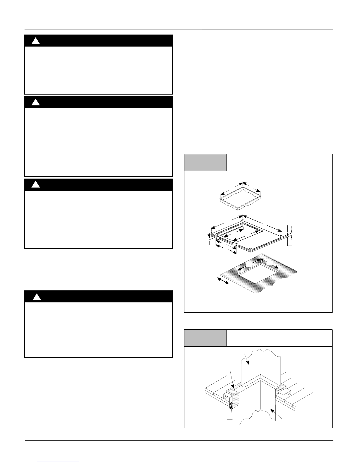
441 01 2613 05
25
Specifications are subject to change without notice
11. Ductwork and Filter (Downflow)
CARBON MONOXIDE POISONING HAZARD
Failure to follow this warning could result in
personal injury or death.
Do NOT draw return air from inside a closet or
utility room where furnace is located. Return air
duct MUST be sealed to furnace casing.
!
WARNING
FIRE HAZARD
Failure to follow this warning could result in bodily
injury, death, and/or property damage.
Side return air duct(s) may cause excessive furnace
and/or air temperatures, which could result in death,
bodily injury, and/or property damage.
Return air duct is to be connected to only the top of
downflow furnace.
!
WARNING
BURN HAZARD
Failure to follow this warning could result in bodily
injury, death, and/or property damage.
The vent may be hot. Failure to install vent shield
properly could result in personal injury.
Install VENT PIPE SHIELD NAHA002VC as
described below.
!
WARNING
Vent Shield
Vent shield is required for all downflow installations. The vent Must
exit out the side of the furnace for all downflow installations. This
places the hot vent pipe (over 300° F/149° C) within reach of
children. Vent shield attaches to side of furnace to cover vent pipe.
See Figure 5 in “Installation” section.
FIRE HAZARD
Failure to follow this warning could result in personal
injury, death, and/or property damage.
Place furnace on noncombustible subbase on
downflow applications, unless installing on
non!combustible flooring.
!
WARNING
Outlet Duct Flange
Downflow installations with cased coils require the furnace outlet
duct flange to be bent outward and flat to mate the outlet of the
furnace to the cased coil.
Sub-Bases for Combustible Floors - Furnace Only
Note: When using the subbase for combustible floors, the
discharge air duct flanges on the furnace MUST be broken down to
provide proper fit up to the subbase. Use duct pliers to bend the
duct flanges flat onto the furnace casing. DO NOT bend the duct
flanges inward (toward the heat exchangers) as air flow
restrictions may occur.
The Subbase for Combustible Floors MUST be used when a
downflow furnace is set on a combustible floor, even when the
furnace is installed on a coil box.
1. Cut the opening in the floor according to the dimensions in
Table 5 because the base is equipped with locating tabs that
center the base over the opening.
The opening in the base is 1
1
/4″ (31.8mm) shorter and 11/8″
(28.6mm) narrower than the minimum required size of the
opening in the floor. This is done to maintain a 1″ (25.4mm)
clearance between the floor and the plenum.
2. Fabricate the plenum to the dimensions given in Table 5.
Note that the dimensions given are outside dimensions.
3. Set the base over the opening in the floor, centering the
opening in the base over the opening in the floor. Fasten the
base to the floor with screws or nails. See Figure 27.
4. Drop the plenum through the opening in the base. The flange
of the plenum should rest on top of the combustible floor base.
Figure 27
Exploded View of Sub!Base for
Furnace ONLY
A
Hole in
Floor
M
N
25-20-46
L
R
H
K
J
P
Plenum
S
T A = 4 1/4” (108mm) Minimum
clearance from back of hole
to wall or other obstruction.
2″ (50.8mm)
1″ (25.4mm)
2″ (50.8mm)
Setting the Base
Figure 28
Furnace/Coil Box
Subbase
Insulation
Wood Screw
Wood Floor
Plenum
25-20-46A
National Excelsior Company
www.excelsiorhvac.com
Subject to change without notice.

26
441 01 2613 05
Specifications are subject to change without notice
Table 5 Sub!bases for Combustible Floors Dimensions in(mm)
Sub!base for
Combustible Floors
Part Number
Sub!base for Combustible
Floor Dimensions
Opening In Floor
Opening In
Base For Plenum
Typical Plenum
Dimensions
H
*
J* K** L M N P R S T
Subbase for Furnace Only
NAHH001SB
1511/
16
(398.5)
283/4 (730.3) 149/16 (369.9) 16(406.4)
161/
4
(412.8)
145/
8
(371.5)
15 (381)
131/
2
(342.9)
15 (381)
131/
2
(342.9)
NAHH002SB
195/
16
(490.5)
283/4 (730.3) 183/16 (462) 16(406.4)
161/
4
(412.8)
181/
4
(463.6)
15 (381)
171/
8
(435.6)
15 (381)
171/
8
(435.6)
NAHH003SB
2215/
16
(582.6)
283/4 (730.3) 2113/16 (554) 16(406.4)
161/
4
(412.8)
217/
8
(555.6)
15 (381)
193/
4
(501.7)
15 (381)
193/
4
(501.7)
Subbase for Coil Box
NAHH004SB
153/
4
(25.4)
209/
16
(522.3)
149/16 (369.9)
161/
16
(408)
161/
4
(412.8)
145/
8
(371.5)
15 (381)
131/
2
(342.9)
15 (381)
131/
2
(
342.9)
NAHH005SB
193/
8
(181.1)
209/
16
(522.3)
183/16 (462)
161/
16
(408)
161/
4
(412.8)
181/
4
(463.6)
15 (381)
171/
8
(435.6)
15 (381)
171/
8
(435.6)
NAHH006SB 23 (284.2)
209/
16
(522.3)
2113/16 (554)
161/
16
(408)
161/
4
(412.8)
217/
8
(555.6)
15 (381)
193/
4
(501.7)
15 (381)
193/
4
(501.7)
*
Outside Dimension
**
Base Spacer Side To Side
Converstion: 1 in = 25.4 mm
Figure 29
Exploded View of Base for
Downflow Cased Coil
25-21-65n
21/
2
″
11/
2
″
Plenum
(63.5mm)
(38.1mm)
Sub-base for Combustible Floors - Downflow Coil
Adapter Box
The subbase for combustible floors is required when a downflow
furnace, used with a downflow coil box, is set on combustible
flooring.
1. Cut the opening in the floor according to the dimensions in
Table 5 because the base is equipped with locating tabs that
center the base over the opening.
The opening in the base is 1
1
/4″〈31.8mm) shorter and 11/8″
(28.6mm) narrower than the minimum required size of the
opening in the floor. This is done to maintain a 1” (25.4mm)
clearance between the floor and the plenum.
2. Fabricate the plenum to the dimensions given in Table 5.
Note that the dimensions given are outside dimensions.
3. Set the base over the opening in the floor, centering the
opening in the base over the opening in the floor. Fasten the
base to the floor with screws or nails. See Figure 28.
4. Drop the plenum through the opening in the base. The flange
of the plenum should rest on top of the combustible floor base.
Consideration must be given to the height of the base to allow for
easy installation of the condensate drain. See Figure 30. This
subbase for combustible floors has been designed so that the
height of the subbase raises the downflow coil off the floor to allow
easy installation of the condensate drain
Condensate Line Raised by Base
Figure 30
25!20!52
Non-Combustible Floor
Set the furnace over the opening in the floor. If necessary, grout
around the base to seal air leaks between the base and the floor.
Duct Connections
In the downflow position, the return!air duct must be connected to
only the top of the furnace. Top return connections can be made by
removing the knockout panel in the furnace base. Return air
connection through the side(s) or back of the furnace is NOT
allowed.
Duct Design and Duct Installation Requirements
See Section 10.
Internal Filter in Top Return Installation
When installing top!mounted filter inside the furnace, install the
filter clips on the edge of the top duct opening with the wider end of
the clips toward the blower as shown in Figure 31. Clips may be
obtained from your distributor or fabricated from sheet metal
National Excelsior Company
www.excelsiorhvac.com
Subject to change without notice.

441 01 2613 05
27
Specifications are subject to change without notice
(Figure 26). Insert filter into side clips first and push filter back until
it is fully engaged into back clip.
Figure 31
Top Mounted Internal Filter
9″
Center Clip
side-to-side
NOTE: If filters are only suitable for heating application,
advise homeowner that filter size may need to be increased if
air conditioning is added.
Addition Of Air Conditioning
See Section 10.
12. Checks and Adjustments
Startup
NOTE: Refer to startup procedures in the Users Information
Manual.
!
ELECTRICAL SHOCK, FIRE, OR EXPLOSION
HAZARD
Failure to follow this warning could result in
personal injury, death, and/or property damage.
If any sparks, odors or unusual noises occur,
immediately shut OFF gas and power to furnace.
Check for wiring errors or obstruction to blower.
WARNING
Gas Supply Pressure
Gas supply pressure should be within minimum and maximum
values listed on rating plate. Pressures are usually set by gas
suppliers.
(See Propane Gas Conversion Kit instruction manual for furnaces
converted to Propane gas.)
Manifold Gas Pressure Adjustment
NOTE: Make adjustment to manifold pressure with burners
operating.
!
FIRE OR EXPLOSION HAZARD
Failure to follow this warning could result in
personal injury, death, and/or property damage.
Turn OFF gas at shut off before connecting
manometer.
WARNING
1. With gas OFF, connect manometer to manifold pressure tap
on outlet of gas valve. See Figure 32. Use a manometer with
a 0 to 12 in wc range.
Typical Gas Valve
Regulator Adjustment
Under Cap
Inlet
Pressure
Tap
1
/8 NPT
INLET
OUTLET
Outlet
Pressure
Tap
1
/8 NPT
IN
OFF
ON
HONEYWELL
Figure 32
2. Turn gas ON. Operate the furnace by using a jumper wire on
the R to W thermostat connection on the control board.
3. Remove manifold pressure adjustment screw cover on
furnace gas valve. Turn adjusting screw counterclockwise to
decrease manifold pressure and clockwise to increase
pressure.
NOTE: Adjustment screw cover MUST be replaced on gas valve
before reading manifold pressure and operating furnace.
4. Set manifold pressure to value shown in Table 6 or Table 7.
5. When the manifold pressure is properly set, replace the
adjustment screw cover on the gas valve.
6. Remove jumper wire from thermostat connection on control
board. Remove manometer connection from manifold
pressure tap, and replace plug in gas valve.
7. Check for leaks at plug.
National Excelsior Company
www.excelsiorhvac.com
Subject to change without notice.

28
441 01 2613 05
Specifications are subject to change without notice
Natural Gas Input Rating Check
The gas meter can be used to measure input to furnace. Check
with gas supplier for actual BTU content.
1. Turn OFF gas supply to all appliances other than furnace and
start furnace. Use jumper wire on R to W.
2. Time how many seconds it takes the smallest dial on the gas
meter to make one complete revolution.
Note: If meter uses a 2 cubic foot dial, divide results (seconds) by
two.
Refer to Example. The Example is based on a natural gas BTU
content of 1,000 BTU’s per cubic foot.
Example (BTUH)
Natural Gas
BTU Content
per cubic foot
No. of Seconds
Per Hour
Time Per Cubic
Foot in
Seconds
BTU Per
Hour
1,000 3,600 48 75,000
1,000 x 3,600 ÷ 48 = 75,000 BTUH
To Determine the appliance kW input rate from a .05m
3
test dial
that has been clocked at 80 seconds for one complete revolution.
Example (kW)
Number of
seconds per
hour
Number of
seconds per
complete
rotation
Size of test dial
(.05m
3
)
kW m3/h
3,600 80 .05 2.25
3,600 ÷ 80 x .05 = 7.2 m3/h
2.25m3/h x 10.35 kWh/m
3
= 23.28 kW
23.28 x 3.412 = 79,431 BTU
3. Remove jumper wire from R to W.
4. Relight all appliances and ensure all pilots are operating.
Orifice Sizing
NOTE: Factory sized orifices for natural gas and Propane gas are
listed in the furnace Technical Support Manual.
Ensure furnace is equipped with the correct main burner orifices.
Refer to Table 6 or Table 7 for correct orifice size and manifold
pressure for a given heating value and specific gravity for natural
and propane gas.
Operation Above 2000′ (610m)Altitude
FIRE, EXPLOSION, CARBON MONOXIDE
POISONING HAZARD
Failure to follow this warning could
result in personal injury, death, and/or property
damage.
This high!altitude gas!conversion shall be done by
a qualified service agency in accordance with the
Manufacturer’s instructions and all applicable
codes and requirements, or in the absence of local
codes, the applicable national codes.
!
WARNING
These furnace may be used at full input rating when installed at
altitudes up to 2000′. When installed above 2000′ (610m), the
input must be decreased 2% (natural) or 4% (Propane) for each
1000′ (305m) above sea level in the USA. In Canada, the input
rating must be derated 5% (natural) or 10% (Propane) for each
1000′ above sea level. This may be accomplished by a simple
adjustment of manifold pressure or an orifice change, or a
combination of a pressure adjustment and an orifice change. The
changes required depend on the installation altitude and the
heating value of the fuel. Table 6 & Table 7 show the proper
furnace manifold pressure and gas orifice size to achieve proper
performance based on elevation above sea level for both natural
gas and propane gas.
To use the natural gas table, first consult your local gas utility for
the heating value of the gas supply. Select the heating value in the
first column and follow across the table until the appropriate
elevation for the installation is reached. The value in the box at the
intersection of the altitude and heating value provides not only the
manifold pressure but also the orifice size. In the natural gas tables
the factory!shipped orifice size is in bold (42). Other sizes must be
obtained from service parts.
High Altitude Input Rate =
Nameplate Sea Level Input Rate x (Multiplier) [USA]
Elevation
ft (m)
High Altitude Multiplier
Natural Gas Propane Gas
2001′ - 3000′
(610 ! 914)
0.95 0.90
3001′ - 4000′
(915 ! 1219)
0.93 0.86
4001′ - 5000′
(1220 ! 1524)
0.91 0.82
5001′ - 6000′
(1524 ! 1829)
0.89 0.78
6001′ - 7000′
(1829 ! 2134)
0.87 0.74
7001′ - 8000′
(2134 ! 2438)
0.85 0.70
* Based on mid!range of elevation.
National Excelsior Company
www.excelsiorhvac.com
Subject to change without notice.
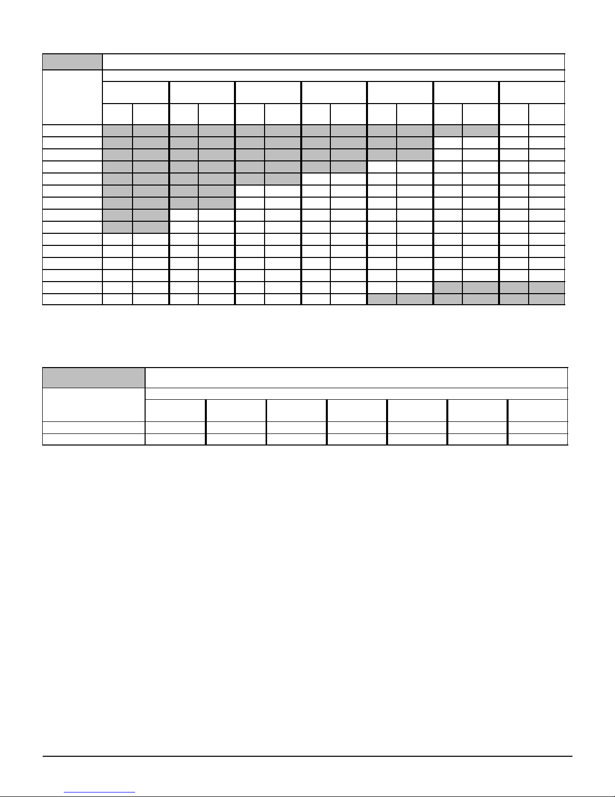
441 01 2613 05
29
Specifications are subject to change without notice
MANIFOLD PRESSURE AND ORIFICE SIZE FOR HIGH ALTITUDE APPLICATIONS
Table 6 NATURAL GAS MANIFOLD PRESSURE (in wc)
HEATING
VALUE
at ALTITUDE
BTU/CU. FT.
MEAN ELEVATION ABOVE SEA LEVEL ! ft(m)
0 to 2000
(0 to 610)
2001 to 3000*
(610 to 914)*
3001 to 4000
(915 to 1219)
4001 to 5000
(1220 to 1524)
5001 to 6000
(1524 to 1829)
6001 to 7000
(1829 to 2134)
7001 to 8000
(2134 to 2438)
Orifice
No.
Manifold
Pressure
Orifice
No.
Manifold
Pressure
Orifice
No.
Manifold
Pressure
Orifice
No.
Manifold
Pressure
Orifice
No.
Manifold
Pressure
Orifice
No.
Manifold
Pressure
Orifice
No.
Manifold
Pressure
700 !! !! !! !! !! !! !! !! !! !! !! !! 41 3.7
725 !! !! !! !! !! !! !! !! !! !! 41 3.7 41 3.4
750 !! !! !! !! !! !! !! !! !! !! 41 3.5 42 3.6
775 !! !! !! !! !! !! !! !! 41 3.6 42 3.6 42 3.3
800 !! !! !! !! !! !! 41 3.6 42 3.7 42 3.4 42 3.1
825 !! !! !! !! 41 3.7 41 3.4 42 3.5 42 3.2 42 2.9
850 !! !! !! !! 41 3.5 42 3.6 42 3.3 42 3.0 42 2.8
875 !! !! 41 3.6 42 3.6 42 3.4 42 3.1 42 2.8 42 2.6
900 !! !! 42 3.7 42 3.4 42 3.2 42 2.9 42 2.7 42 2.5
925 41 3.7 42 3.5 42 3.3 42 3.0 42 2.8 42 2.5 44 3.3
950 41 3.5 42 3.3 42 3.1 42 2.9 42 2.6 42 2.4 44 3.1
975 42 3.7 42 3.2 42 2.9 42 2.7 42 2.5 44 3.2 45 3.6
1000 42 3.5 42 3.0 42 2.8 42 2.6 42 2.4 45 3.7 45 3.4
1050 42 3.2 42 2.7 42 2.5 44 3.3 45 3.6 !! !! !! !!
1100 43 3.6 42 2.5 44 3.2 45 3.6 !! !! !! !! !! !!
Conversion: 1 in wc = .25 kPa
NOTE: Natural gas data is based on 0.60 specific gravity. For fuels with different specific gravity consult the National Fuel Gas Code ANSI Z223.1/NFPA
54!2009 or National Standard of Canada, Natural Gas And Propane Installation Code CSA B149.1!05.
* In the USA, derating of these furnaces at 2% (Natural Gas) and 4% (Propane Gas) has been tested and design!certified by CSA.
In Canada, the input rating must be derated 5% (Natural Gas) and 10% (Propane Gas) for altitudes of 2,000 to 4,500 (610 to
1372m) above sea level. Use the 2001 to 3000 (610 to 914m) column in Table 6 and Table 7.
Table 7 PROPANE GAS MANIFOLD PRESSURE (in wc)
HEATING VALUE
at ALTITUDE
BTU/CU. FT.
MEAN ELEVATION ABOVE SEA LEVEL ! ft(m)
0 to 2000
(0 to 610)
2001 to 3000*
(610 to 914)*
3001 to 4000
(915 to 1219)
4001 to 5000
(1220 to 1524)
5001 to 6000
(1524 to 1829)
6001 to 7000
(1829 to 2134)
7001 to 8000
(2134 to 2438)
2500 10.0 10.0 9.0 10.0 9.4 8.5 10.0
Orifice Size #54 #54 #54 #55 #55 #55 #56
Conversion: 1 in wc = .25 kPa
NOTE: Propane data is based on 1.53 specific gravity. For fuels with different specific gravity consult the National Fuel Gas Code ANSI Z223.1/NFPA
54!2009 or National Standard Of Canada, Natural Gas And Propane Installation Code CSA B149.1!05.
* In the USA, derating of these furnaces at 2% (Natural Gas) and 4% (Propane Gas) has been tested and design!certified by CSA.
In Canada, the input rating must be derated 5% (Natural Gas) and 10% (Propane Gas) for altitudes of 2,000 to 4,500 (610 to
1372m) above sea level. Use the 2001 to 3000 (610 to 914m) column in Table 6 and Table 7.
The burner orifice part nos. are as follows:
Orifice #41 1096942 Orifice #42 1011351
Orifice #43 1011377 Orifice #44 1011352
Orifice #45 1011353 Orifice #54 1011376
Orifice #55 1011354 Orifice #56 1011355
High Altitude Air Pressure Switch
The factory!installed pressure switch need NOT be changed for
any furnace installations from sea level up to and including 8,000′
(2438m) altitude
Changing Orifices
1. After disconnecting power and gas supply to the furnace,
remove the burner compartment door, exposing the burner
compartment.
2. Disconnect gas line from gas valve so manifold can be
removed.
3. Disconnect wiring at gas valve. Be sure to note the proper
location of all electrical wiring before being disconnected.
4. Remove the four (4) screws holding the manifold and gas
valve to the manifold supports. Do not discard any screws.
See Figure 33.
5. Carefully remove the manifold assembly.
6. Remove the orifices from the manifold and replace them with
proper sized orifices. See Figure 34.
7. Tighten orifices so they are seated and gas!tight. See
Figure 34.
8. Reassemble all parts in reverse order as removed. Be sure to
engage the main burner orifices in the proper openings in the
burners.
National Excelsior Company
www.excelsiorhvac.com
Subject to change without notice.

30
441 01 2613 05
Specifications are subject to change without notice
Figure 33
Manifold
25-25-00
Some Models may vary
9. After reassembling, turn gas on and check all joints for gas
leaks using a soapy solution. All leaks must be repaired
immediately.
Figure 34
Clearances
Measure from face of orifice to the
back side of the manifold.
1.11″ (28.2mm)
1.21″ (30.8mm)
Propane Conversion
An accessory kit shall be used to convert to propane gas use, see
the furnace rating plate for the Propane conversion accessory kit
part number.
CARBON MONOXIDE POISONING HAZARD
Failure
to follow this warning may result in
personal injury, death, and/or property
damage.
NOx inserts for use with Natural Gas units
ONLY. If Propane Gas is required, NOx inserts
must be removed.
!
CAUTION
FIRE, EXPLOSION, UNIT DAMAGE HAZARD
Failure
to follow this warning may result in
personal injury, death, and/or property
damage.
A Propane conversion accessory kit is required when operating the furnace with
Propane gas.
!
WARNING
*8MPLs and N8MPLs contain NOx inserts.
FOR PROPANE CONVERSION REMOVE SCREWS THAT
SECURE THE NOX INSERT AND DISCARD INSERT.
Reinstall screws. See Figure 36
NOTE: It is very important to reinstall the NOx insert mounting
screws.
Figure 35
Removing NOx inserts
25-40-03
Main Burner Flame Check
Allow the furnace to run approximately 10 minutes. Then inspect
the main burner flames. See Figure 36.
Check for the following:
• Stable and blue flames. Dust may cause orange tips or
wisps of yellow, but flames MUST NOT have solid, yellow
tips.
• Flames extending directly from burner into heat exchanger.
• Flames do NOT touch sides of heat exchanger
If any problems with main burner flames are noted, it may be
necessary to adjust gas pressures or check for drafts.
Main Burner
Burner Face
10!10!78
Figure 36
NOTE: For Ignitor location see Figure 37.
Ignitor Location in(mm)
Figure 37
5
/16(8)
1
/4(6.4)
2
1/
16
(52.4)
NOTE: Flame sensor has a different orientation in all 050 models.
National Excelsior Company
www.excelsiorhvac.com
Subject to change without notice.

441 01 2613 05
31
Specifications are subject to change without notice
Air Temperature Rise Check
!
REDUCED FURNACE LIFE HAZARD
Failure to follow this caution may result in reduced
furnace life.
Use ONLY the blower motor speed taps insert
indicated in the Circulation Air Blower Data for
setting air temperature rise.
CAUTION
The blower speed MUST be set to give the correct air temperature
rise through the furnace as marked on the rating plate.
Temperature rise is the difference between supply and return air
temperatures.
To check temperature rise, use the following procedure:
1. Place thermometers in supply and return air registers as close
to furnace as possible, avoiding direct radiant heat from heat
exchangers.
2. Operate furnace for 10 minutes with all the registers and duct
dampers open by using a jumper wire on R to W thermostat
connections on the control board.
3. Take readings and compare with range specified on rating
plate.
4. If the air temperature rise is not in the correct range, the
blower speed must be changed. A higher blower speed will
lower the temperature rise. A lower blower speed will increase
the temperature rise.
5. Remove the jumper wire after the adjustments are complete.
Changing Blower Speed
ELECTRICAL SHOCK HAZARD
Failure to follow this warning could result in
personal injury, death and/or component damage.
Turn OFF power to furnace, lockout, and tag switch
with a suitable warning label before changing
speed taps.
!
WARNING
NOTE: The speed taps that the manufacturer sets at the factory
for this furnace are based on a nominal 400 CFM per ton cooling
and the basic mid range on the temperature rise for heating.
Since the manufacturer cannot predict the static pressure
that will be applied to the furnace, it is the responsibility of the
installer dealer/contractor to select the proper speed tap
leads for the application when the furnace is installed.
If it is necessary to change speeds, refer to steps below.
1. Refer to Furnace Wiring Diagram for location of the heating
and cooling speed taps located on the electronic furnace
control as well as location of unused blower motor speed
leads. Use the chart (Table 8 ) to determine the blower motor
speed settings.
Table 8 Blower Speed Chart
Wire Color Motor Speed
Black High
Orange* Med!High
Blue Med!Low
Red Low
* Med!High speed may not be provided on all models.
2. Change the heat or cool blower motor speed by removing the
motor speed lead from the “Heat” or “Cool” terminal and
replace it with the desired motor speed lead from the “M1” or
“M2” location. Connect the wire previously removed from the
“Heat” or “Cool” terminal to the vacated “M1” or “M2”
terminal.
3. If the same speed must be used for both heating and cooling,
remove the undesired motor speed lead from the “Heat” or
“Cool” terminal and connect that lead to the open terminal at
“M1” or “M2” location or tape off. Attach a jumper between
the “Heat” and “Cool” terminals and the remaining motor
speed lead.
Note: When using the same speed on motors with (4) speed
leads, it will be necessary to tape off the terminal of the motor
speed lead removed from the “Heat” or “Cool” terminal with
electrical tape since an open terminal will not be available at
the “M1” or “M2” location.
Thoroughly check the system after modification to ensure the
proper operation of the circulating air blower in all modes of
operation.
Continuous-Fan Operation using “G”
Energizing the “G” terminal on the furnace control provides
continuous fan operation. This is done by connecting the G
terminal of the thermostat to the G terminal on the furnace control.
When the FAN switch is turned from auto to ON the fan will operate
continuously at “HEAT” speed. EAC will be energized in this
mode.
NOTE: In heating, the fan will turn off during furnace ignition and
warm up then restart at heating speed.
Hard Wired Continuous-Fan Operation
A terminal is provided on the furnace control board located in the
circulating air blower compartment for operation of the
continuous!fan option. This connection is intended for the low
speed motor tap, and has a lower contact rating (8 amps) than the
heat and cool taps. When the low speed blower lead is connected
to this terminal, this will provide low speed blower operation
whenever the other two speeds (Heat or Cool) are not energized.
EAC is not powered in this mode.
Thoroughly check the system after modification to ensure the
proper operation of the circulating air blower in all modes of
operation.
Separate speed selections for Heat, Cool, and
Continuous-Fan
Connect low speed lead from circulating air motor to the “Cont”
terminal at the furnace control board. The appropriate motor leads
should already be connected to the “Heat” and “Cool” terminals.
Heating and Continuous-Fan Speed the Same
If it is necessary to operate the heating speed and continuous!fan
speed using the same blower speed, connect a jumper between
the “Heat” and “Cont” terminals on the furnace control board.
Note: There should be only ONE motor lead going to the “Heat”
and “Cont” terminals.
National Excelsior Company
www.excelsiorhvac.com
Subject to change without notice.

32
441 01 2613 05
Specifications are subject to change without notice
13. Furnace Maintenance
FIRE, EXPLOSION, OR CARBON MONOXIDE
POISONING HAZARDS
Failure to follow this warning could result in
personal injury, death, and/or property damage.
It is recommended that the furnace be inspected
and serviced on an annual basis (before the heating
season) by a qualified service agency.
!
WARNING
See “User’s Information Manual”.
ELECTRICAL SHOCK, FIRE OR EXPLOSION HAZARD
Failure to follow this warning could result in
dangerous operation, personal injury, death, or
property damage.
Improper servicing could result in dangerous
operation, injury, death or property damage.
• Before servicing, disconnect all electrical
power to furnace, lockout, and tag switch with a
suitable warning label.
• When servicing controls, label all wires prior to
disconnecting. Reconnect wires correctly.
• Verify proper operation after servicing.
!
WARNING
National Excelsior Company
www.excelsiorhvac.com
Subject to change without notice.

441 01 2613 05
33
Specifications are subject to change without notice
14. Sequence of Operation & Diagnostics
The following is the normal operating sequence.
Cooling (Y) Request:
24VAC signals applied to Y & G terminals of FCB (furnace control board)
• Cool motor speed is energized after 5 second Cool Fan On Delay time.
Y & G signals removed from FCB
• Cool motor speed is de!energized after 90 second Cool Fan Off Delay time.
Continuous Circulating Fan (G) Request:
24 VAC signal is applied to G terminal of the FCB.
• Heat motor speed is energized without delay.
G signal removed from FCB.
• Heat motor speed is de!energized after 5 second delay.
NOTE 1) Furnace de!energizes the fan during the heat exchanger warm!up period on a call for Heating that occurs during a G request
unless a blower motor lead is connected to the Cont terminal on the FCB, in which case see NOTE 2).
NOTE 2) Heating or Cooling requests received during a Fan request cause the fan speed to change to the appropriate heat or cool
speed after the Fan on Delay time expires. The fan returns to continuous circulating speed after the selected Fan Off Delay time expires
following loss of the Heating or Cooling request.
Continuous Circulating Fan Hard-Wired (Cont) Request:
Field selected low speed motor tap installed on “CONT” terminal.
• Low speed is energized when power applied to furnace. Operates at this speed continuously while there are no other
blower demands from furnace control. Fan demands from furnace control for heat, cool or “G” will override hard!wired speed tap.
NOTE 3) EAC is NOT active for hard!wired mode but IS active for fan demands from furnace control for heat, cool and “G”.
Heating (W) Request:
Heating (W) Request:
• 24 VAC signal applied to W terminal of FCB.
• Inducer motor turns on and the pressure switch(es) close(s).
• Following a 15 second prepurge delay after the pressure switches closes, the igniter begins a 17 second warm!up.
• The gas valve is energized, the main burners light and flame is sensed.
• The igniter is de!energized after the main burners ignite.
• FCB will delay blower operation for the 30 seconds timed from the opening of the gas valve.
W signal removed from FCB.
• The gas valve de!energizes and the main burners go out.
• The inducer runs for a 15 second postpurge period.
• The fan stays at Heat speed.
• The fan de!energizes after the selected Heat Fan Off Delay time expires, timed from the gas valve de!energizing.
HUMIDIFIER ! The 24V HUM is energized when the pressure switch closes on a call for heat. The 115V HUM (called HUM on Control)
is energized when the inducer is energized.
ELECTRONIC AIR CLEANER ! EAC is energized when there is a blower speed call. It is NOT energized when blower operates in the
hard!wired continuous fan mode.
NOTE 4) If a new Heating request arrives while the control is waiting in the Heat Fan Off Delay time, the FCB will wait for the selected
Heat Fan Off Delay then start a new heating cycle as long as the heat call remains.
National Excelsior Company
www.excelsiorhvac.com
Subject to change without notice.

34
441 01 2613 05
Specifications are subject to change without notice
Heating Request with Gas Shut Off:
24 VAC signal applied to W terminal of FCB.
The FCB will attempt 4 cycles for ignition then go to soft lockout for 3 hours then try for ignition again as long as the heat call remains.
Power reset will clear lockout.
• Inducer motor turns on
• Following a 15 second prepurge delay, the igniter begins warm up.
• The igniter glows red!hot for 22 seconds, then turns off. The FCB flashes error code 6.
• The igniter stays off for 17 seconds, then begins to warm up again.
• The igniter glows red hot for 22 seconds then turns off. The FCB continues flashing error code 6.
• The igniter stays off for 17 seconds, then begins to warm up again.
• The igniter glows red hot for 22 seconds then turns off. The FCB continues flashing error code 6.
• The igniter stays off for 17 seconds, then begins to warm up again.
• The igniter glows red hot for 22 seconds then turns off. The FCB proceeds to soft lockout and stops flashing error code 6 and begins
flashing error code 6 + 1.
• The inducer motor de!energizes after a 15 second post purge.
Control Board Diagnostic Codes (See Figure 38)
OFF = 24VAC or 115VAC is off, fuse is open
Heartbeat = Normal operation or no previous Diagnostic Code
ON SOLID = Soft Lockout ! Furnace Control Error (1 hr delay)
If code repeats immediately following power reset then replace control
1 Flash = Not used
2 Flashes = Pressure switch(es) closed when should be open
3 Flashes = Pressure switch open when should be closed
4 Flashes = Limit or roll!out switch open (less than 2 minutes)
5 Flashes = Flame sensed out of sequence
6 Flashes = Failure to ignite or flame sense lost while running
6 + 1 Flashes = Soft Lockout ! Max trials for ignition reached (3hr delay)
7 Flashes = Soft Lockout ! Limit or roll!out switch open longer than 2 minutes (1 hr delay)
(roll!out switch requires manual reset)
8 Flashes = Permanent Lockout ! Gas valve relay contact stuck closed or miswired gas valve (power reset only)
10 Flashes = Line voltage (115VAC) polarity reversed. If twinned, refer to twinning kit instructions
* If status code recall is needed, briefly (2!3 seconds) remove then reconnect one limit switch wire (main or rollout) to display last stored
status code. Do not remove power or blower door before initiating status code recall or code will be lost. Code is automatically cleared
after 72 hours or upon power reset.
* Proper flame sense microamps: 0.7 microamps D.C. minimum, 2.0 ! 4.0 microamps nominal
Figure 38 Control Board
Diagnostic Light
115 VAC
HUM
FUSE
24 VAC
HUM
National Excelsior Company
www.excelsiorhvac.com
Subject to change without notice.

35
441 01 2613 05
Models
N8MPN050B12B2 N8MPL050B12B2
N8MPN075B12B2 N8MPL075B12B2
N8MPN075F16B2 N8MPL075F16B2
N8MPN100F14B2 N8MPL100F20B2
N8MPN100F20B2 N8MPL100J22B2
N8MPN100J22B2 N8MPL125J20B2
N8MPN125J20B2 N8MPL125J22B2
N8MPN125J22B2
*8MPN050B12B2 *8MPL050B12B2
*8MPN075B12B2 *8MPL075B12B2
*8MPN075F16B2 *8MPL075F16B2
*8MPN100F14B2 *8MPL100F20B2
*8MPN100F20B2 *8MPL100J20B2
*8MPN100J20B2 *8MPL125J20B2
*8MPN125J20B2
*8MPN150J20B2
* Denotes Brand
International Comfort Products, LLC
Lewisburg, TN 37091 U.S.A.
Save This Manual For Future Reference
National Excelsior Company
www.excelsiorhvac.com
Subject to change without notice.

36
441 01 2613 05
Specifications are subject to change without notice
Manufacturers Number (Mfr No -See Rating Plate)
ALL Models (N8MPN)
Specifications
N8MPN
050B12
N8MPN
075B12
N8MPN
075F16
N8MPN
100F14
N8MPN
100F20
N8MPN
100J22
N8MPN
125J20
N8MPN
125J22
General
Input (Btuh)
Output (Btuh)
Temp. Rise (
oF/o
C)
50,000
40,000
35-65/19-36
75,000
60,000
35-65/19-36
75,000
60,000
25-55/14-30
100,000
80,000
30-60/17-33
100,000
80,000
35-65/19-36
100,000
80,000
30-60/17-33
125,000
100,000
30-60/17-33
125,000
100,000
30-60/17-33
Electrical (Volts/Hz)
115/60 115/60 115/60 115/60 115/60 115/60 115/60 115/60
Rating Plate Amps.
9.7 9.2 9.7 8.9 11.7 13.2 11.7 13.2
Gas Type
Nat Propane Nat Propane Nat Propane Nat Propane Nat Propane Nat Propane Nat Propane Nat Propane
Transformer Size (VA)
T'stat Heat Anticipator
40
.50
Gas & Ignition
Std. Main Orifices (No/Size)
2/#42 2/#54 3/#42 3/#54 3/#42 3/#54 4/#42 4/#54 4/#42 4/#54 4/#42 4/#54 5/#42 5/#54 5/#42 5/#54
Gas Valve Honeywell
Regulation Type
Manifold Press (in wc/Pa)
VR8205S
SNAP
3.5/
872
10.0/
2490
3.5/
872
10.0/
2490
3.5/
872
10.0/
2490
3.5/
872
10.0/
2490
3.5/
872
10.0/
2490
3.5/
872
10.0/
2490
3.5/
872
10.0/
2490
3.5/
872
10.0/
2490
Ignition Type/Series Hot Surface
Combustion
Flue Outlet Size (Inches)
4 4 4 4 4 4 4 4
Limits & Controls
Thermal Sensor (
oF/o
C)
Limit Control
300/149
See Parts List
300/149
See Parts List
300/149
See Parts List
300/149
See Parts List
300/149
See Parts List
300/149
See Parts List
300/149
See Parts List
300/149
See Parts List
Std. Pressure Sw.
(Part No)
Press -Close (in wc/Pa)
Press -Open (in wc/Pa)
1013529
-0.69/-172
-0.59/-147
Furnace Control (Type)
Furnace Control On delay
(Timed-secs) Off delay
Integrated
30
60,100,140,180
Blower Data
Size Inches (D x W)
Motor Type/H.P.
Cap. Mfd/Volts
Filter Type (600 FPM)
Filter Size inches
(Not Supplied) mm
1600 CFM and over inch(qty)
mm(qty)
Min. Cool Cap. (Tons)
Max. Cool Cap. (Tons)
11-8
PSC/
1
/
2
10/370
Washable
14x25x1
355x635x25
--
--
1.5
3
11-8
PSC/
1
/
2
7.5/370
Washable
14x25x1
355x635x25
--
--
1.5
3
11-10
PSC/
1
/
2
10/370
Washable
16x25x1
406x635x25
16x25x1(2)
406x635x25(2)
3
4
11-10
PSC/
1
/
2
7.5/370
Washable
16x25x1
406x635x25
--
-2
3.5
11-10
PSC/
1
/
2
10/370
Washable
16x25x1(2)
406x635x25(2)
16x25x1(2)
406x635x25(2)
3
5
11-10
PSC/
3
/
4
40/370
Washable
20x25x1
508x635x25
16x25x1
406x635x25(2))
3
5.5
11-10
PSC/
1
/
2
10/370
Washable
20x25x1
508x635x25
16x25x1
406x635x25(2)
3
5
11-10
PSC/
3
/
4
40/370
Washable
20x25x1
508x635x25
16x25x1
406x635x25(2)
3
5.5
Gas Conversion Kits
Nat to Propane NAHA001LP (1172958*)
Propane to Nat NAHA001NG (1172960*)
* Must be ordered from Service Parts
National Excelsior Company
www.excelsiorhvac.com
Subject to change without notice.

441 01 2613 05
Specifications are subject to change without notice
37
Manufacturers Number (Mfr No -See Rating Plate)
ALL Models (N8MPL)
Specifications
N8MPL
050B12
N8MPL
075B12
N8MPL
075F16
N8MPL
100F20
N8MPL
100J22
N8MPL
125J20
N8MPL
125J22
General
Input (Btuh)
Output (Btuh)
Temp. Rise (
oF/o
C)
50,000
40,000
35-65/19-36
75,000
60,000
35-65/19-36
75,000
60,000
25-55/14-30
100,000
80,000
35-65/19-36
100,000
80,000
30-60/17-33
125,000
100,000
30-60/17-33
125,000
100,000
30-60/17-33
Electrical (Volts/Hz) 115/60 115/60 115/60 115/60 115/60 115/60 115/60
Rating Plate Amps. 9.7 9.2 9.7 11.7 13.2 11.7 13.2
Gas Type Nat Propane Nat Propane Nat Propane Nat Propane Nat Propane Nat Propane Nat Propane
Transformer Size (VA)
T'stat Heat Anticipator
40
.50
Gas & Ignition
Std. Main Orifices (No/Size)
2/#42 2/#54 3/#42 3/#54 3/#42 3/#54 4/#42 4/#54 4/#42 4/#54 5/#42 5/#54 5/#42 5/#54
Gas Valve Honeywell
Regulation Type
Manifold Press. (in wc/Pa)
VR 8205S
SNAP
3.5/
872
10.0/
2490
3.5/
872
10.0/
2490
3.5/
872
10.0/
2490
3.5/
872
10.0/
2490
3.5/
872
10.0/
2490
3.5/
872
10.0/
2490
3.5/
872
10.0/
2490
Ignition Type/Series Hot Surface
Combustion
Flue Outlet Size (Inches)
4
4 4
4 4
4 4
Limits & Controls
Thermal Sensor (
oF/o
C)
Limit Control
300/149
See Parts List
300/149
See Parts Listt
300/149
See Parts List
300/149
See Parts List
300/149
See Parts List
300/149
See Parts List
300/149
See Parts List
Std. Pressure Sw. (Part No)
Press -Close (in wc/Pa)
Press -Open (in wc/Pa)
1013529
-0.69/-172
-0.59/-147
Furnace Control (Type)
Furnace Control On delay
(Timed-secs) Off delay
Integrated
30
60,100,140,180
Blower Data
Size Inches (D x W)
Motor Type/H.P.
Cap. Mfd/Volts
Filter Type (600 FPM)
Filter Size inches
(Not Supplied) mm
1600 CFM and over inch(qty)
mm(qty)
Min. Cool Cap. (Tons)
Max. Cool Cap. (Tons)
11-8
PSC/
1
/
2
10/370
Washable
14x25x1
355x635x25
--
--
1.5
3
11-8
PSC/
1
/
2
7.5/370
Washable
14x25x1
355x635x25
--
--
1.5
3
11-10
PSC/
1
/
2
10/370
Washable
16x25x1
406x635x25
16x25x1(2)
406x635x25(2)
3
4
11-10
PSC/
1
/
2
10/370
Washable
16x25x1
406x635x25
16x25x1(2)
406x635x25(2)
3
5
11-10
PSC/
3
/
4
40/370
Washable
20x25x1
508x635x25
16x25x1(2)
406x635x25(2)
3
5.5
11-10
PSC/
1
/
2
10/370
Washable
20x25x1
508x635x25
16x25x1(2)
406x635x25(2)
3
5
11-10
PSC/
3
/
4
40/370
Washable
20x25x1
508x635x25
16x25x1(2)
406x635x25(2)
3
5.5
Gas Conversion Kits
Nat to Propane NAHA001LP (1172958*)
Propane to Nat NAHA001NG (1172960*)
* Must be ordered from Service Parts
National Excelsior Company
www.excelsiorhvac.com
Subject to change without notice.

38
441 01 2613 05
Specifications are subject to change without notice
Manufacturers Number (Mfr No -See Rating Plate)
ALL Models (*8MPN)
Specifications
*8MPN
050B12
*8MPN
075B12
*8MPN
075F16
*8MPN
100F14
*8MPN
100F20
*8MPN
100J20
*8MPN
125J20
*8MPN
150J20
General
Input (Btuh)
Output (Btuh)
Temp. Rise (
oF/o
C)
50,000
40,000
35-65/19-36
75,000
60,000
30-60/17-33
75,000
60,000
30-60/17-33
100,000
81,000
35-65/19-36
100,000
81,000
35-65/19-36
100,000
81,000
35-65/19-36
125,000
101,000
35-65/19-36
150,000
121,000
35-65/19-36
Electrical (Volts/Hz) 115/60 115/60 115/60 115/60 115/60 115/60 115/60 115/60
Rating Plate Amps. 9.7 9.0 9.7 9.2 12.0 12.0 12.0 13.5
Gas Type Nat Propane Nat Propane Nat Propane Nat Propane Nat Propane Nat Propane Nat Propane Nat Propane
Transformer Size (VA)
T'stat Heat Anticipator
40
.50
Gas & Ignition
Std. Main Orifices (No/Size)
2/#42 2/#54 3/#42 3/#54 3/#42 3/#54 4/#42 4/#54 4/#42 4/#54 4/#42 4/#54 5/#42 5/#54 6/#42 6/#54
Gas Valve Honeywell
Regulation Type
Manifold Press. (in wc/Pa)
VR 8205S
SNAP
3.5/
872
10.0/
2490
3.5/
872
10.0/
2490
3.5/
872
10.0/
2490
3.5/
872
10.0/
2490
3.5/
872
10.0/
2490
3.5/
872
10.0/
2490
3.5/
872
10.0/
2490
3.5/
872
10.0/
2490
Ignition Type/Series Hot Surface
Combustion
Flue Outlet Size (Inches)
4
4 4 4
4 4
4 4
Limits & Controls
Thermal Sensor (
oF/o
C)
Limit Control
Auxiliary Limit (
oF/o
C)
300/149
See Parts List
130/54
300/149
See Parts List
130/54
300/149
See Parts List
130/54
300/149
See Parts List
130/54
300/149
See Parts List
130/54
300/149
See Parts List
130/54
300/149
See Parts List
130/54
300/149
See Parts List
130/54
Std. Pressure Sw. (Part No)
Press -Close (in wc/Pa)
Press -Open (in wc/Pa)
1013529
-0.69/-172
-0.59/-147
Furnace Control (Type)
Furnace Control On
(Timed-secs) Off
Integrated
30
60,100,140,180
Blower Data
Size Inches (D x W)
Motor Type/H.P.
Cap. Mfd/Volts
Filter Type (600 FPM)
Filter Size inches
(Not Supplied) mm
1600 CFM and over inch(qty)
mm(qty)
Min. Cool Cap. (Tons)
Max. Cool Cap. (Tons)
11-8
PSC/
1
/
2
10/370
Washable
14x25x1
355x635x25
--
--
1.5
3
11-8
PSC/
1
/
2
7.5/370
Washable
14x25x1
355x635x25
--
--
1.5
3
11-10
PSC/
1
/
2
10/370
Washable
16x25x1
406x635x25
16x25x1(2)
406x635x25(2)
3
4
11-10
PSC/
1
/
2
7.5/370
Washable
16x25x1
406x635x25
--
-2
3.5
11-10
PSC/
1
/
2
10/370
Washable
16x25x1
406x635x25
16x25x1(2)
406x635x25(2)
3
5
11-10
PSC/
1
/
2
10/370
Washable
20x25x1
508x635x25
16x25x1(2)
406x635x25(2)
3
5
11-10
PSC/
1
/
2
10/370
Washable
20x25x1
508x635x25
16x25x1(2)
406x635x25(2)
3
5
12-12
PSC/
3
/
4
40/370
Washable
20x25x1
508x635x25
16x25x1(2)
406x635x25(2)
3
5
Gas Conversion Kits
Nat to Propane NAHA001LP (1172958*)
Propane to Nat NAHA001NG (1172960*)
* Must be ordered from Service Parts
National Excelsior Company
www.excelsiorhvac.com
Subject to change without notice.

441 01 2613 05
Specifications are subject to change without notice
39
Manufacturers Number (Mfr No -See Rating Plate)
ALL Models (*8MPL)
Specifications
*8MPL
050B12
*8MPL
075B12
*8MPL
075F16
*8MPL
100F20
*8MPL
100J20
*8MPL
125J20
General
Input (Btuh)
Output (Btuh)
Temp. Rise (
oF/o
C)
50,000
40,000
35-65/19-36
75,000
60,000
30-60/17-33
75,000
60,000
30-60/17-33
100,000
81,000
35-65/19-36
100,000
81,000
35-65/19-36
125,000
101,000
35-65/19-36
Electrical (Volts/Hz) 115/60 115/60 115/60 115/60 115/60 115/60
Rating Plate Amps. 9.7 9.0 9.7 12.0 12.0 12.0
Gas Type Nat Propane Nat Propane Nat Propane Nat Propane Nat Propane Nat Propane
Transformer Size (VA)
T'stat Heat Anticipator
40
.50
Gas & Ignition
Std. Main Orifices (No/Size)
2/#42 2/#54 3/#42 3/#54 3/#42 3/#54 4/#42 4/#54 4/#42 4/#54 5/#42 5/#54
Gas Valve Honeywell
Regulation Type
Manifold Press. (in wc/Pa)
VR 8205S
SNAP
3.5/
872
10.0/
2490
3.5/
872
10.0/
2490
3.5/
872
10.0/
2490
3.5/
872
10.0/
2490
3.5/
872
10.0/
2490
3.5/
872
10.0/
2490
Ignition Type Hot Surface
Combustion
Flue Outlet Size (Inches)
4
4 4
4 4
4
Limits & Controls
Thermal Sensor (
oF/o
C)
Limit Control
Auxiliary Limit (
oF/o
C)
300/149
See Parts List
130/54
300/149
See Parts List
130/54
300/149
See Parts List
130/54
300/149
See Parts List
130/54
300/149
See Parts List
130/54
300/149
See Parts List
130/54
Std. Pressure Sw. (Part No)
Press -Close (in wc/Pa)
Press -Open (in wc/Pa)
1013529
-0.69/-172
-0.59/-147
Furnace Control (Type)
Furnace Control On delay
(Timed-secs) Off delay
Integrated
30
60,100,140,180
Blower Data
Size Inches (D x W)
Motor Amps/RPM
Motor Type/H.P.
Cap. Mfd/Volts
Filter Type
Filter Size inches
(Not Supplied) mm
1600 CFM and over inch(qty)
mm(qty)
Min. Cool Cap. (Tons)
Max. Cool Cap. (Tons)
11-8
10.3/1100
PSC/
1
/
2
10/370
Washable
14x25x1
355x635x25
--
--
1.5
3
11-8
8/1050
PSC/
1
/
2
7.5/370
Washable
14x25x1
355x635x25
--
--
1.5
3
11-10
10.3/1100
PSC/
1
/
2
10/370
Washable
16x25x1
406x635x25
16x25x1(2)
406x635x25(2)
3
4
11-10
10/1050
PSC/
1
/
2
10/370
Washable
16x25x1
406x635x25
16x25x1(2)
406x635x25(2)
3
5
11-10
11.9/900
PSC/
1
/
2
10/370
Washable
20x25x1
508x635x25
16x25x1(2)
506x635x25(2)
3
5
11-10
10/1050
PSC/
1
/
2
10/370
Washable
20x25x1
508x635x25
16x25x1(2)
406x635x25(2)
3
5
Gas Conversion Kits
Nat to Propane NAHA001LP (1172958*)
Propane to Nat NAHA001NG (1172960*)
* Must be ordered from Service Parts
National Excelsior Company
www.excelsiorhvac.com
Subject to change without notice.

40
441 01 2613 05
Specifications are subject to change without notice
15. Circulation Air Blower Data (CFM)
N8MPN/L050B12 & *8MPN/L050B12 (1)(8) * Denotes Brand
Exterrnal Static Pressure
(in wc/Pa)
Air Delivery in CFM (L/s)
Furnace Rated @0.5 in wc (125 Pa) ESP
TAP LOW MED L MED H HIGH
in wc Pa CFM L/s CFM L/s CFM L/s CFM L/s
0.10 25 472 223 704 332 1167 551 1387 655
0.20 50 419 198 671 317 1135 536 1338 631
0.30 75 365 172 638 301 1102 520 1288 608
0.40 100 328 155 605 286 1069 504 1241 586
0.50 125 290 137 572 270 1035 488 1194 563
0.60 149 250 118 547 258 987 466 1132 534
0.70 174 209 99 522 246 939 443 1070 505
0.80 199 --- --- 483 228 880 415 1004 474
0.90 224 --- --- 443 209 820 387 937 442
1.00 249 --- --- 370 175 753 355 858 405
N8MPN/L075B12 & *8MPN/L075B12 (1)(8) * Denotes Brand
Exterrnal Static Pressure
(in wc/Pa)
Air Delivery in CFM (L/s)
Furnace Rated @0.5 in wc (125 Pa) ESP
TAP LOW MED L MED H HIGH
in wc Pa CFM L/s CFM L/s CFM L/s CFM L/s
0.1 25 695 328 963 454 1220 576 1559 736
0.2 50 670 316 946 446 1202 567 1511 713
0.3 75 644 304 928 438 1183 558 1463 690
0.4 100 616 291 901 425 1151 543 1412 666
0.5 125 588 277 873 412 1118 528 1361 642
0.6 149 564 266 822 388 1068 504 1300 613
0.7 174 540 255 771 364 1017 480 1239 585
0.8 199 502 237 723 341 959 453 1161 548
0.9 224 463 218 675 319 900 425 1083 511
1 249 413 195 615 290 835 394 998 471
N8MPN/L075F16 & *8MPN/L075F16 (1)(3)(8) * Denotes Brand
Exterrnal Static Pressure
(in wc/Pa)
Air Delivery in CFM (L/s)
Furnace Rated @0.5 in wc (125 Pa) ESP
TAP LOW MED L MED H HIGH
in wc Pa CFM L/s CFM L/s CFM L/s CFM L/s
0.1 25 598 282 841 397 1427 673 1861 878
0.2 50 499 235 795 375 1406 664 1816 857
0.3 75 400 189 748 353 1384 653 1770 835
0.4 100 345 163 708 334 1364 644 1724 814
0.5 125 289 136 667 315 1343 634 1677 791
0.6 149 263 124 625 295 1299 613 1612 761
0.7 174 236 111 582 275 1254 592 1547 730
0.8 199 --- --- 530 250 1192 563 1454 686
0.9 224 --- --- 477 225 1129 533 1360 642
1 249 --- --- 436 206 1016 479 1262 596
NOTE: (1) Data based on Bottom Only or One Side return.
(2) Data based on Both Sides or Bottom plus One Side
(3) 075F16 Reduce airflow by 5% if Bottom Only return.
(4) 100F20 Reduce airflow by 10% if Bottom Only return.
(5) 125J20 Reduce airflow by 5% if Bottom Only return.
(6) 125J22 Reduce airflow by 10% if Bottom Only return.
(7) 150J20 Reduce airflow by 10% if Bottom Only return.
(8) Gray area is above maximum temperature rise range.
NOTE: (1) Gray area is above maximum temperature rise range.
# CFM ! Cubic feet per minute airflow.
L/s ! Liters per second
Filter required for each return!air inlet. Airflow performance includes 1″ (25.4mm)
washable ! 600 FPM (3.0 m/s) max filter media.
N8MPN100F14 & *8MPN100F14 (1)(8) * Denotes Brand
Exterrnal Static Pressure
(in wc/Pa)
Air Delivery in CFM (L/s)
Furnace Rated @0.5 in wc (125 Pa) ESP
TAP LOW MED L MED H HIGH
in wc Pa CFM L/s CFM L/s CFM L/s CFM L/s
0.1 25 770 363 949 448 1328 627 1760 831
0.2 50 709 335 911 430 1282 605 1718 811
0.3 75 648 306 873 412 1235 583 1675 790
0.4 100 596 281 823 388 1175 555 1613 761
0.5 125 544 257 772 364 1115 526 1551 732
0.6 149 501 236 728 344 1076 508 1478 697
0.7 174 457 216 684 323 1036 489 1404 663
0.8 199 409 193 628 296 966 456 1310 618
0.9 224 361 170 572 270 895 422 1215 573
1 249 308 145 507 239 811 383 1093 516
N8MPN/L100F20 & *8MPN/L100F20 (2)(4)(8) * Denotes Brand
Exterrnal Static Pressure
(in wc/Pa)
Air Delivery in CFM (L/s)
Furnace Rated @0.5 in wc (125 Pa) ESP
TAP LOW MED L MED H HIGH
in wc Pa CFM L/s CFM L/s CFM L/s CFM L/s
0.1 25 831 392 1125 531 1582 747 2216 1046
0.2 50 823 388 1124 530 1585 748 2198 1037
0.3 75 814 384 1123 530 1588 749 2179 1028
0.4 100 798 377 1120 529 1583 747 2127 1004
0.5 125 781 369 1117 527 1577 744 2074 979
0.6 149 749 353 1085 512 1559 736 1992 940
0.7 174 717 338 1053 497 1541 727 1909 901
0.8 199 663 313 1009 476 1457 688 1827 862
0.9 224 609 287 964 455 1373 648 1745 824
1 249 561 265 888 419 1307 617 1641 774
N8MPN/L100J22 (2)(8)
Exterrnal Static Pressure
(in wc/Pa)
Air Delivery in CFM (L/s)
Furnace Rated @0.5 in wc (125 Pa) ESP
TAP LOW MED L MED H HIGH
in wc Pa CFM L/s CFM L/s CFM L/s CFM L/s
0.1 25 1785 842 1997 942 2292 1082 2519 1189
0.2 50 1765 833 1970 930 2245 1059 2468 1165
0.3 75 1741 822 1941 916 2206 1041 2410 1137
0.4 100 1711 807 1902 898 2154 1017 2351 1109
0.5 125 1674 790 1861 878 2097 990 2284 1078
0.6 149 1633 771 1807 853 2036 961 2206 1041
0.7 174 1581 746 1749 825 1965 927 2121 1001
0.8 199 1517 716 1683 794 1883 889 2030 958
0.9 224 1428 674 1597 754 1793 846 1928 910
1 249 1326 626 1478 697 1667 787 1814 856
MAX CFM (L/s) for Factory Washable Filters
Filter Size in(mm) CFM L/s
14 x 25 356 x 635 1400 661
16 x 25 406 x 635 1600 755
20 x 25 508 x 635 2000 944
24 x 25 610 x 635 2500 1180
Max CFM (L/s) based on 600 FPM (3.0 m/s)
*See Table for bellyband location on motor
* Denotes Brand
National Excelsior Company
www.excelsiorhvac.com
Subject to change without notice.

441 01 2613 05
Specifications are subject to change without notice
41
Circulation Air Blower Data Continued
*8MPN/L100J20 (2)(8) * Denotes Brand
Exterrnal Static Pressure
(in wc/Pa)
Air Delivery in CFM (L/s)
Furnace Rated @0.5 in wc (125 Pa) ESP
TAP LOW MED L MED H HIGH
in wc Pa CFM L/s CFM L/s CFM L/s CFM L/s
0.1 25 773 365 1045 493 1453 686 2147 1013
0.2 50 766 361 1029 486 1461 689 2142 1011
0.3 75 755 356 1037 489 1469 693 2128 1004
0.4 100 737 348 1037 489 1469 693 2113 997
0.5 125 712 336 1020 481 1459 689 2078 981
0.6 149 683 322 1013 478 1446 682 2029 958
0.7 174 647 305 979 462 1424 672 1963 926
0.8 199 603 285 942 445 1400 661 1892 893
0.9 224 554 261 894 422 1347 636 1795 847
1 249 497 235 828 391 1262 596 1705 805
N8MPN/L125J22 (2)(6)(8)
Exterrnal Static Pressure
(in wc/Pa)
Air Delivery in CFM (L/s)
Furnace Rated @0.5 in wc (125 Pa) ESP
TAP LOW MED L MED H HIGH
in wc Pa CFM L/s CFM L/s CFM L/s CFM L/s
0.1 25 1901 897 2121 1001 2362 1115 2463 1162
0.2 50 1867 881 2077 980 2303 1087 2424 1144
0.3 75 1833 865 2033 959 2244 1059 2385 1126
0.4 100 1789 844 1985 937 2172 1025 2301 1086
0.5 125 1745 824 1936 914 2100 991 2217 1046
0.6 149 1685 795 1855 875 1997 942 2125 1003
0.7 174 1624 766 1773 837 1894 894 2033 959
0.8 199 1533 723 1671 789 1804 851 1927 909
0.9 224 1442 681 1569 740 1714 809 1821 859
1 249 1329 627 1455 687 1583 747 1685 795
NOTE: (1) Data based on Bottom Only or One Side return.
(2) Data based on Both Sides or Bottom plus One Side
(3) 075F16 Reduce airflow by 5% if Bottom Only return.
(4) 100F20 Reduce airflow by 10% if Bottom Only return.
(5) 125J20 Reduce airflow by 5% if Bottom Only return.
(6) 125J22 Reduce airflow by 10% if Bottom Only return.
(7) 150J20 Reduce airflow by 10% if Bottom Only return.
(8) Gray area is above maximum temperature rise range.
* Denotes Brand
NOTE: (1) Gray area is above maximum temperature rise range.
# CFM ! Cubic feet per minute airflow.
L/s ! Liters per second
Filter required for each return!air inlet. Airflow performance includes 1″ (25.4mm)
washable ! 600 FPM (3.0 m/s) max filter media.
N8MPN/L125J20 & *8MPN/L125J20 (2)(5)(8) * Denotes Brand
Exterrnal Static Pressure
(in wc/Pa)
Air Delivery in CFM (L/s)
Furnace Rated @0.5 in wc (125 Pa) ESP
TAP LOW MED L MED H HIGH
in wc Pa CFM L/s CFM L/s CFM L/s CFM L/s
0.1 25 860 406 1149 542 1666 786 2147 1013
0.2 50 848 400 1154 545 1622 765 2137 1008
0.3 75 836 395 1158 546 1577 744 2126 1003
0.4 100 821 387 1149 542 1569 740 2137 1008
0.5 125 805 380 1140 538 1561 737 2148 1014
0.6 149 782 369 1111 524 1539 726 2035 960
0.7 174 758 358 1081 510 1516 715 1922 907
0.8 199 710 335 1045 493 1472 695 1845 871
0.9 224 661 312 1009 476 1428 674 1767 834
1 249 614 290 925 437 1357 640 1663 785
*8MPN150J20 (2)(7)(8) * Denotes Brand
Exterrnal Static Pressure
(in wc/Pa)
Air Delivery in CFM (L/s)
Furnace Rated @0.5 in wc (125 Pa) ESP
TAP LOW MED L MED H HIGH
in wc Pa CFM L/s CFM L/s CFM L/s CFM L/s
0.1 25 1656 782 1915 904 2168 1023 2385 1126
0.2 50 1620 765 1851 874 2129 1005 2360 1114
0.3 75 1583 747 1787 843 2090 986 2335 1102
0.4 100 1545 729 1742 822 2044 965 2274 1073
0.5 125 1507 711 1697 801 1997 942 2212 1044
0.6 149 1449 684 1647 777 1927 909 2149 1014
0.7 174 1390 656 1596 753 1856 876 2085 984
0.8 199 1301 614 1521 718 1755 828 1992 940
0.9 224 1212 572 1445 682 1654 781 1898 896
1 249 1125 531 1337 631 1561 737 1777 839
MAX CFM (L/s) for Factory Washable Filters
Filter Size in(mm) CFM L/s
14 x 25 356 x 635 1400 661
16 x 25 406 x 635 1600 755
20 x 25 508 x 635 2000 944
24 x 25 610 x 635 2500 1180
Max CFM (L/s) based on 600 FPM (3.0 m/s)
*See Table for bellyband location on motor
Bellyband Location on Motor
A Dimension
A
Bellyband Location on Motor
A Dimension
Model *8MPN *8MPL inches mm Model N8MPN N8MPL inches mm
050B12B2 X X 13/
8
35.1 050B12B2 X X 13/
8
35.1
075B12B2 X X 13/
8
35.1 075B12B2 X X 13/
8
35.1
075F16B2 X X 13/
8
35.1 075F16B2 X X 13/
8
35.1
100F14B2 X N/A 13/
8
35.1 100F14B2 X N/A 13/
8
35.1
100F20B2 X X 17/
8
46 100F20B2 X X 17/
8
46
100J20B2 X X 17/
8
46 125J22B2 X X 15/
8
41.9
125J20B2 X X 17/
8
46 125J20B2 X X 17/
8
46
150J20B2 X N/A 15/
8
41.9 125J22B2 X X 15/
8
41.9
National Excelsior Company
www.excelsiorhvac.com
Subject to change without notice.

441 01 2613 05
42
Specifications are subject to change without notice
Wiring Diagram N8MPN/L, *8MPN/L
National Excelsior Company
www.excelsiorhvac.com
Subject to change without notice.

National Excelsior Company
www.excelsiorhvac.com
Subject to change without notice.
INDUCED!COMBUSTION GAS FURNACE
PARTS REPLACEMENT INFORMATION GUIDE
CASING GROUP
Outer door
Blower door
Door bracket
Top filler plate
Bottom encloser
INDUCER GROUP
Housing assembly
Pressure switch
Inducer assembly
Vent elbow assembly
Inducer blower gasket
BLOWER GROUP
Blower housing
Blower hanger
Blower partition
Blower cutoff (Panel)
Blower motor
Blower wheel
Capacitor (where used)
Capacitor strap (where used)
FILTER GROUP
Filter(s) ! washable (1!in.)
HEAT EXCHANGER GROUP
Heat exchanger cell
Cell Panel
Low NOx baffle (California models only)
ELECTRICAL GROUP
Control bracket
Junction box
Limit switch(es)
Circuit board
Door switch
Transformer
Wiring harness 24v
Wiring harness 120v
GAS CONTROL GROUP
Manifold
Burner Assembly
Orifice
PRODUCT NOMENCLATURE
Flame sensor
Hot surface ignitor
Gas valve
Manual reset limit switch
Burner support assembly
!
FIRE, EXPLOSION, ELECTRICAL
SHOCK AND CARBON MONOXIDE
POISONING HAZARD
Failure to follow this warning could result in
dangerous operation, personal injury, death
or property damage.
Improper installation, adjustment, alteration,
service, maintenance, or use can cause
carbon monoxide poisoning, explosion, fire,
electrical shock, or other conditions which
may cause personal injury or property
damage. Consult a qualified installer,
service agency, local gas supplier, or your
distributor or branch for information or
assistance. The qualified installer or
agency must use only factory-authorized
and listed kits or accessories when
modifying this product.
WARNING
* 8 MP L 0 75 B 1 2 B #
* = Brand Specific Engineering Rev.
Brand Efficiency Denotes minor change
8 = Non!Condensing, 80+% Gas Furnace
9 = Condensing, 90+% Gas Furnace Marketing Digit
Installation Configuration Denotes major change
UP = Upflow DN = Downflow Cooling Airflow
UH = Upflow/Horizontal HZ = Horizontal 08 = 800 CFM 16 = 1600 CFM
DH = Downflow/Horizontal 12 = 1200 CFM 20 = 2000 CFM
MP = Multiposition, Upflow/Downflow/Horizontal 14 = 1400 CFM 22 = 2200 CFM
Major Design Feature
1 = One (Single) Pipe N = Single Stage Cabinet Width
2 = Two Pipe P = PVC Vent B = 15.5″ Wide J = 22.8″ Wide
D = 1 or 2 Pipe T = Two Stage F = 19.1″ Wide L = 24.5″ Wide
L = Low NOx V = Variable Speed Input (Nominal MBTUH)
* Denotes Brand (C, H, T)
Have available the product/model number and the serial number located on the unit rating plate to ensure correct replacement parts.
TO OBTAIN INFORMATION ON PARTS: Consult your installing dealer or the classified section of your local telephone
directory under the “Heating Equipment“ or “Air Conditioning Contractors and Systems” headings for dealer listing by brand
name, or contact:
International Comfort Products, LLC
Consumer Relations Department
P.O. Box 128
Lewisburg, TN 37091, USA
931!270!4100
441 01 2314 05
Specifications are subject to change without notice.
43

THIS PAGE LEFT
National Excelsior Company
www.excelsiorhvac.com
Subject to change without notice.
BLANK
INTENTIONALLY
44
Specifications are subject to change without notice.
441 01 2314 05
 Loading...