

International comfort products PAF Series, APFM Series Installation Instructions Manual
SINGLE PACKAGE AIR CONDITIONERS
PAF & APFM Series -- 2 to 5 TON
Printed in U.S.A.
519 01 1102 00 10--25-- 01
Safety Labeling and Signal Words
Danger, Warning and Caution
The signal words DANGER, WARNING and CAUTION are
used to identify levels of hazard seriousness. The signal
word DANGER is only used on product labels to signify an
immediate hazard. The signal words WARNING and
CAUTION will be used on product labels and throughout
this manual and other manuals that may apply to the
product.
Signal Words
DANGER -- Immediate hazards which WILL result in
severe personal injury or death.
WARNING -- Hazards or unsafe practices which COULD
result in severe personal injury or death.
CAUTION -- Hazards or unsafe practices which COULD
result in minor personal injury or product or property
damage.
Signal Words in Manuals
The signal word WARNING is used throughout this manual
in the following manner:
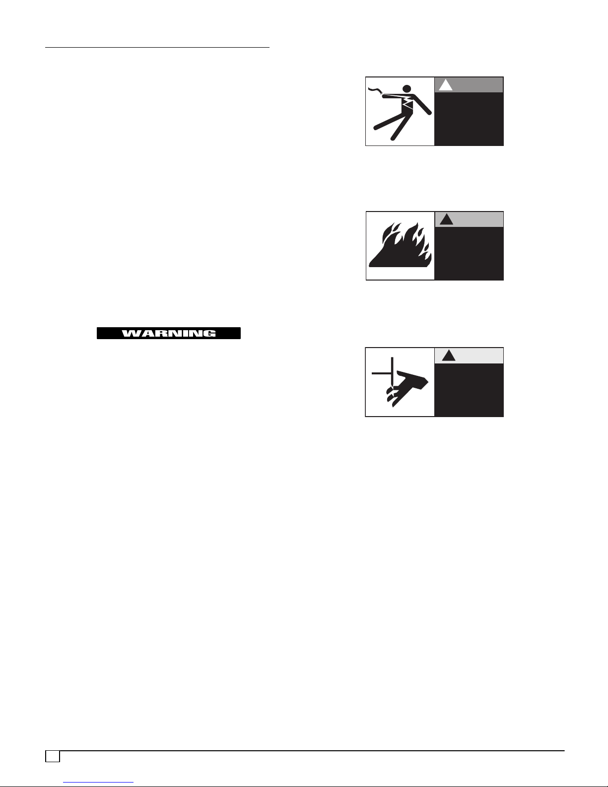
Danger Label
White lettering on a black background except the word
DANGER which is white with a red background.
DANGER
!
Electric Shock Hazard.
Turn Off All Power
Before Servicing.
Warning Label
White lettering on a black background except the word
WARNING which is black with an orange background.
WARNING
!
Fire Hazard.
Use copper wire only.
Failure to observe could
result in property
damage, bodily injury
or death.
Caution Label
White lettering on a black background except the word
CAUTION which is black with a yellow background.
The signal word CAUTION is used throughout this manual
in the following manner:
CAUTION
Product Labeling
Signal words are used in combination with colors and/or
pictures on product labels. Following are examples of
product labels with explanations of the colors used.
CAUTION
!
Cuts and Abrasion Hazard.
Wear gloves and handle
with care.
Failure to observe could
result in bodily injury.
2
519 01 1102 00
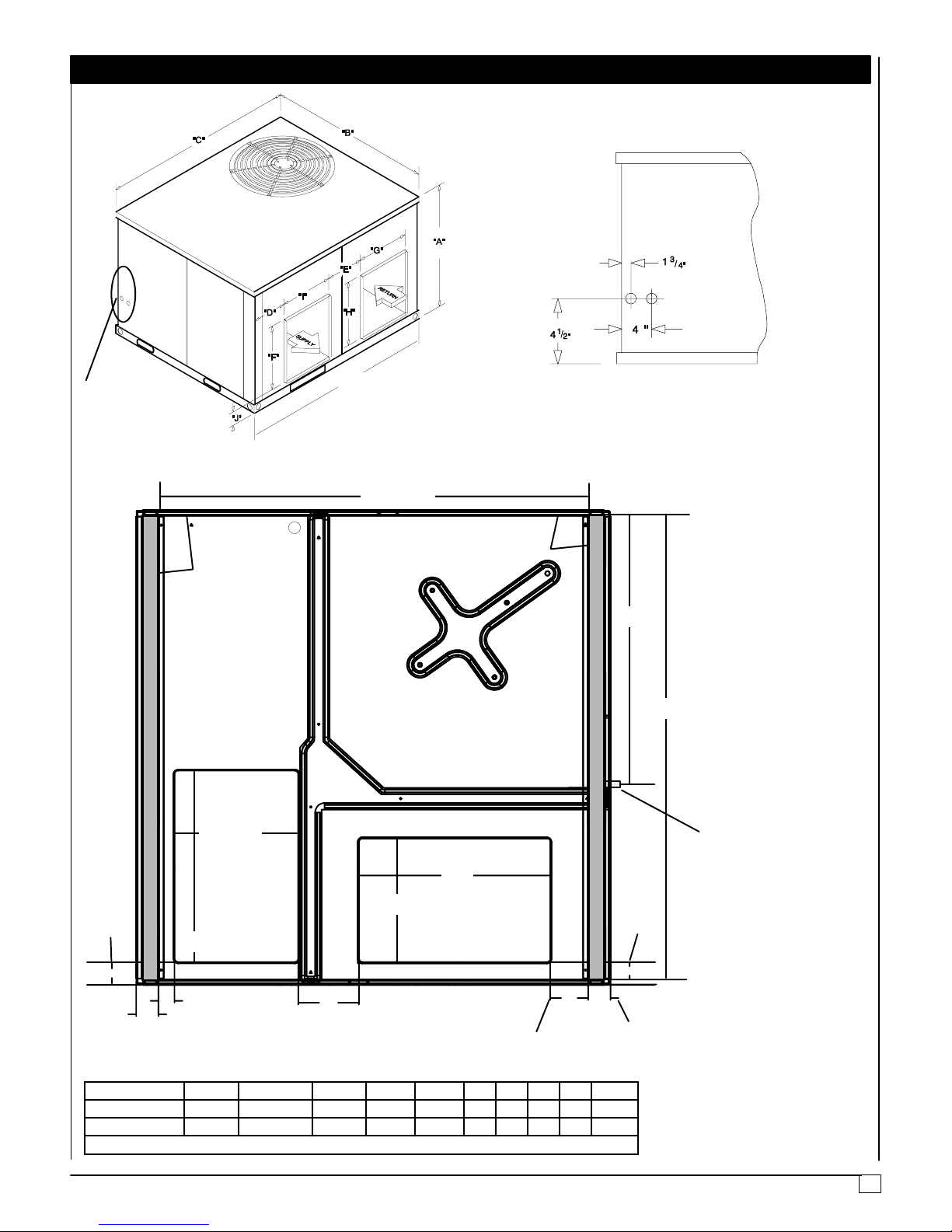
UNIT DIMENSIONS
2TO5TON
See
Detail
46--1/2”
BASE PAN -- CHASSIS
42--3/4**
BASE RAIL
BASE RAIL
27
46--1/8**
12--1/4
SUPPLY
2--1/4
19
1--9/16
2--3/16
UNIT SIZE A B C D E F G H I J
2TO3--1/2Ton 29 --1/2 47--1/2 47- -1/2 3 9--1/2 12 14 12 14 4--1/2
4TO5Ton 37--1/2 47--1/2 47--1/2 4 6--1/2 19 19 12 12 4--1/2
** Measured from inside to inside on base rails.
Condensate Drain
19
12--1/4
RETURN
1--3/4
6
2--3/16
3--3/4
519 01 1102 00
3
SAFE INSTALLATION
Installation or repairs made by unqualified persons can result
in hazards to you and others. Installation MUST conform with
local building codes or, in the absence of local codes, with the
ANSI Z223.1 and the National Electrical Code NFPA70--1990 or
in Canada the National Standard CAN/CGA B149--1 and CSA
C.22.1 -- Canadian Electrical Code Part 1.
The information contained in this manual is intended for use
by a qualified service technician familiar with safety procedures and equipped with the proper tools and test instruments.
Failure to carefully read and follow all instructions in this
manual can result in furnace malfunction, property damage,
personal injury and/or death.
· Seal supply and return air ducts.
· Check to see that filters are installed correctly and are
the proper type an size.
NOTE: It is the personal responsibility and obligation of the
customer to contact a qualified installer to ensure that the
installation is adequate and conforms to governing codes
and ordinances.
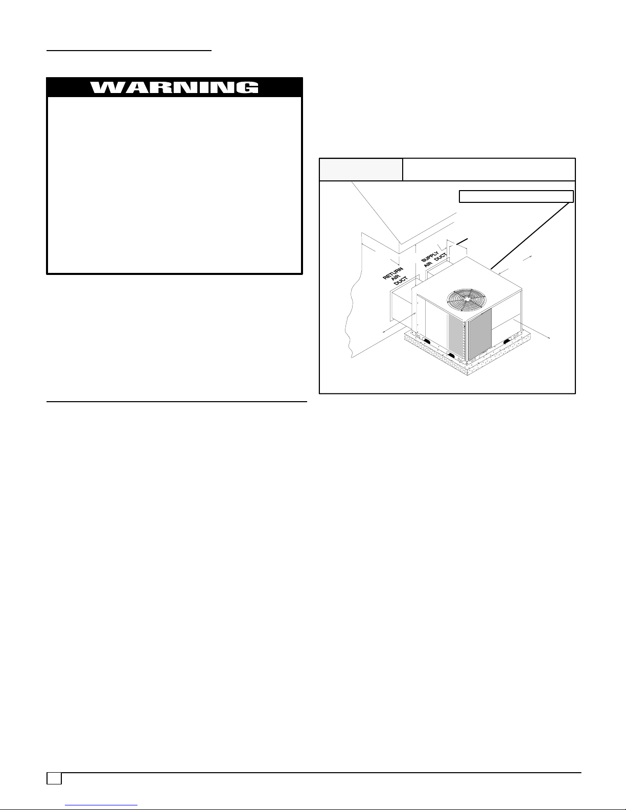
Minimum Clearances to Combustible Construction
Condenser Inlet 30²...................................
Blower Service (Side) 30²..............................
Control Service Side 30²...............................
Clearance between 3 Ft. Overhang
and Top of Unit 30²........................
Combustible Base
(Wood or Class A, B or C
roof covering material) 0²....................
FIGURE 1
36’’
30’’
Minimum Clearances and Access Panels
30’’
(B Chassis Shown)
Blower Compartment Panel
Small Chassis -- 2’’
Large Chassis -- 6’’
2’’
30’’
30’’
80--00--01
LOCATING THE UNIT
ACCESS PANELS
See FIGURE 1 for a general view of unit and location of
access panels.
CLEARANCES
The location MUST allow for minimum clearances and
should not be adjacent to a patio or other area where the
unit’s operating sound level might be objectionable. (see
FIGURE 1). In addition, local codes MUST be observed.
NOTE: Units with available filter racks, need a 26² minimum
clearance at side of unit for removal of filters. See chart
below if unit is going to be placed near combustible
construction or materials.
While minimum clearances are acceptable for safety
reasons, they may not allow adequate air circulation around
the unit for proper operation in the cooling mode. Whenever
possible, it is desirable to allow additional clearance,
especially around the condenser inlet and discharge
openings.
Do NOT install the unit in a location that will permit
discharged air from the condenser to recirculate to the
condenser inlet.
CAUTION
Do NOT operate unit in a corrosive atmosphere containing chlorine, fluorine, or any other corrosive
chemicals.
INSTALLATION
NOTICE
Unit will NOT operate properly unless it is installed level front to rear and side to side. The slope MUST NOT be
greater than
1
/8² per foot (10mm per meter). For side to
side leveling, the drain side MUST always be lower.
Ground Level Installation
Ground level platform requirements:
-- The unit MUST be situated to provide safe access for
servicing.
-- Platform may be made of either concrete or pressure
treated wood and MUST be level and strong enough to
support unit weight.
-- Position platform separate from building foundation.
-- Install in well--drained area, with top surface of platform
above grade level.
-- Platform must be high enough to allow for proper condensate trap installation and drainage. See FIGURE 2
and associated text for more information about condensate drainage.
4
519 01 1102 00
Rooftop Installation
Rooftop platform requirements:
-- The unit MUST be situated to provide safe access for
servicing.
-- The existing roof structure MUST be adequate to support the weight of the unit or the roof MUST be
reinforced.
Check the weight of the unit in relation to the roof structure and local building codes or ordinances and
reinforce roof structure if necessary. See the last page
of this manual for unit weights.
-- Support for the unit MUST be level and strong enough
to carry unit weight. The support may consist of a platform or a combination of platform and roof beams or
curb.
-- S e e Hoisting section for hoisting instructions.
HOISTING
NOTE: All access panels MUST be secured in place before
hoisting.
The unit should be hoisted with two lifting slings. Attach the
slings to rigging shackles that have been hooked through
holes in the base rail.
Two spreader bars MUST be placed on top of the unit to
protect the unit from damage from the pressure exerted by
the slings. Make sure that all equipment is adequate to
handle the weight of the unit and that the slings will not allow
the unit to shift.
Refer to on the back cover of this manual for illustrated
rigging instructions and weight chart.
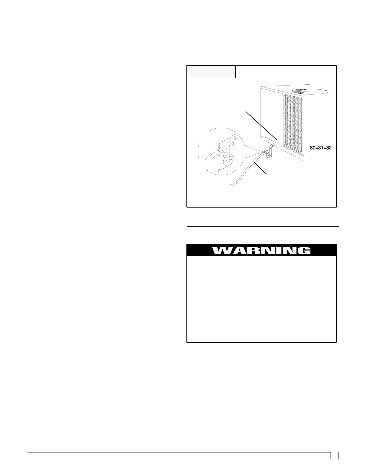
outlet from trap MUST be at least 1² (25.4mm) below top of
outlet from unit. Install the trap as near to the unit as
possible for proper drainage.
3
A
/4² (19.1mm) drain line MUST be installed if required by
local codes or if location of unit requires it. Run the drain line
to an open drain or other suitable disposal point.
FIGURE 2
3
/4² (19.1mm)
Female PVC
Fitting
1²
(25.4mm)
2² (50.8mm)
* Condensate trap MUST be installed.
Condensate Drain Information*
3
/4² (19.1mm)
Drain Line
Electrical Wiring
DOWNFLOW CONVERSION
NOTE: In downflow applications with roof curbs or jack
stands, the center rail under the unit must be removed. The
center rail is attached to the base rail with screws.
These units are adaptable to downflow use. To convert to
downflow use, follow these steps:
1. Remove the blockoff plates found in the return air
compartment and the supply air compartment.
NOTE: Blockoff plate in the supply air compartment only
contains one screw. If reinstalling plate, back part of plate
MUST fit into mating dimples on flange. To reinstall, slant
plate into dimples, then put plate into position and fasten
with screw.
2. Install the removed plates on the horizontal return and
supply air openings.
3. Install roof curb on the building. Be sure to follow all
directions included with curb and all applicable building
codes in your installation.
Condensate Drain
The condensate drain outlet is a
3
/4² (19.1mm) female PVC
connection located at the bottom on the left hand side (see
FIGURE 2).
The circulating blower creates a negative pressure on the
condensate drain line that can prevent the condensate from
draining properly. To combat this negative pressure, a field
supplied condensate trap that will allow a standing column
ofwaterofatleast2² (50.8mm) MUST be installed . Top of
Electrical shock hazard.
Disconnect power at fuse box or service panel
before making any electrical connections.
Unit MUST be grounded to electrical service panel.
Failure to follow this warning can result in property damage, personal injury, and/or death.
NOTE: All electrical work MUST conform with the require-
ments of local codes and ordinances and in the United
States with National Electrical Code ANSl/NFPA 70--1990
(or current edition) and in Canada with CSA C22.1 -- Canadian Electrical Code Part 1 (or current edition). Provide line
voltage power supply from a separate fused circuit with a
disconnect switch (when required) located within sight of
the unit. Supply voltage, amperage, wire, fuse and disconnect switch sizes MUST conform with specifications in the
Parts List and on the unit rating plate.
Wiring MUST be protected from possible mechanical damage and MUST NOT interfere with removal of access
panels, filters, etc.
519 01 1102 00
5
 Loading...