

International Comfort Product HMD Series, HMD-163, HMD-179, HMD-124, HMD-146 Installation Instructions And Homeowner's Manual
...
Models :
HMD
Save these instructions for future reference.
Printed in Canada
DNS
-
0450 Rev A
OIL FIRED HOT
WATER BOILER
Manufactured by :
International Comfort Product
Division of UTC Canada Corporation
3400, Industriel blvd, Sherbrooke, Qc, Canada
Caution : Do not tamper with
the unit or its controls.
Call a qualified service
technician.
2003/05/06 X40014 Rev. E

PART 1
INSTALLATION
WARNING
• This boiler has been designed to provide you with
comfort, savings and reliability for many years to
come. Its performances, however, depends on the
appliance being installed, brought on-line, and
maintained correctly in accordance with the
instructions provided in this manual.
• This boiler is equipped with a burner designed to
burn only No.2 fuel oil (furnace oil). Never attempt
to burn used motor oil or any oil containing
gasoline.
• Make sure that the boiler and system are filled
with water and that all air has been bled before
attempting to start the burner.
• Never operate the burner above the maximum
temperature indicated on the boiler nameplate.
• Never attempt to start the burner when the
combustion chamber contains excess oil, is
overheated, or when a strong smell of oil
permeates the appliance.
• Close oil valves if the boiler has not to be used for
extended period of time.
• Never store garbage or combustibles near the
boiler.
• Never burn garbage or paper in your boiler.
• DO NOT TAMPER WITH THE UNIT OR THE
CONTROLS.
We recommend that you have a qualified
technician install your boiler.
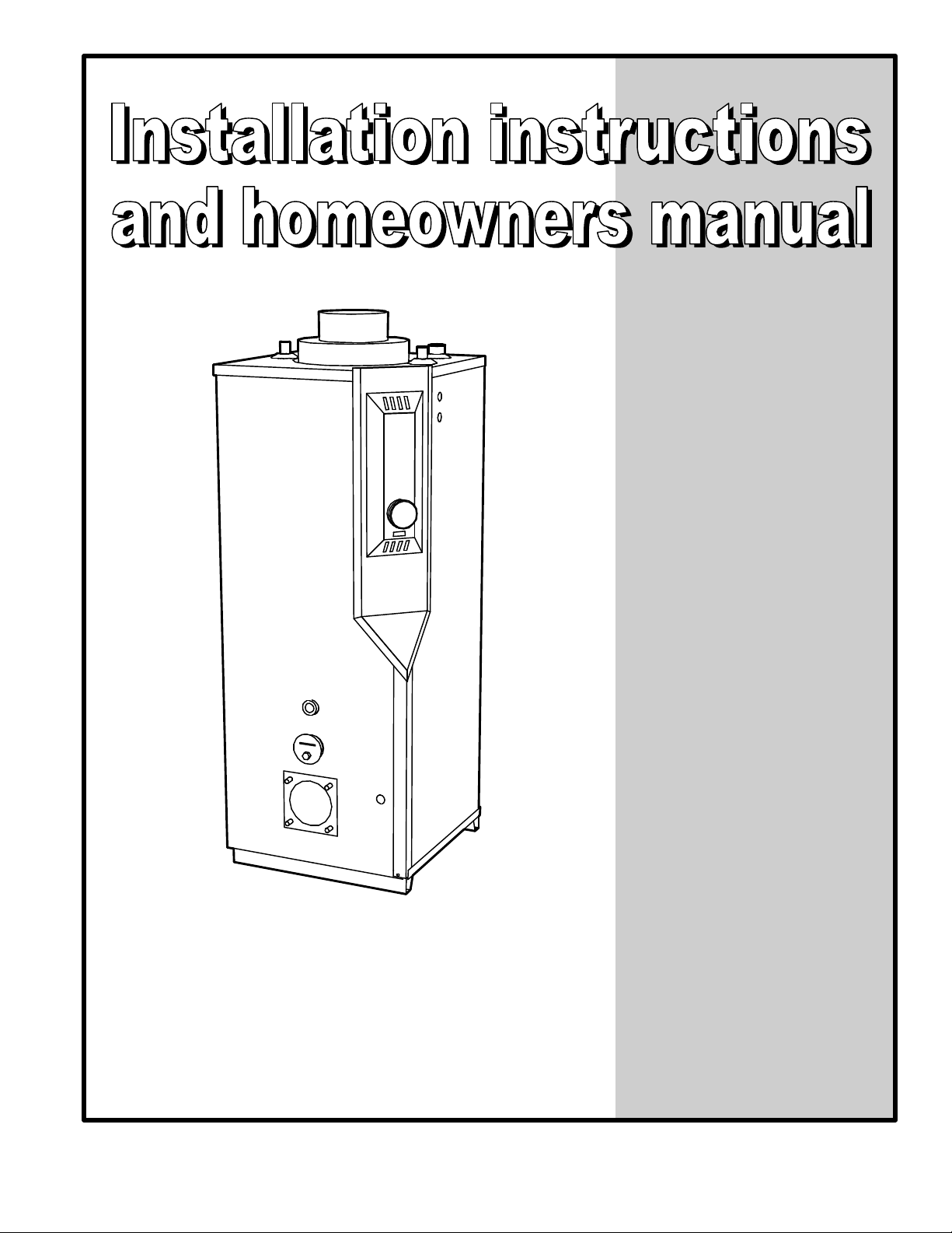
1) UNIT IDENTIFICATION
It is very important that you consult the figure 1 to
recognise the characteristics of the “HMD” serie.
HMD boiler with potable hot water stainless steel tankin-tank and with a flue-pipe of 7 inches diameter. The
models are identified HMD-124, HMD-135, HMD-146,
HMD-163 and HMD-179 and are available with Riello
burner.
2) DELIVERY
Check carefully your boiler upon delivery for any
evidence of damage that may have occurred during
shipping and handling. Any claims for damages or lost
parts must be made with the transport company.
3) INSTALLATION
Your unit must be installed according to regulations
set down by competent authorities. See CSA B139
installation code.
3.1) Location
Your boiler must be installed in a clean and dry area,
as close as possible to a chimney. These boilers are
not approved for installation on combustible floor.
3.2) Clearances
The following minimum clearances from combustible
surfaces must be observed.
Top : 24 inches
Flue-pipe : 9 inches
First side : 3 inches
Other side : 24 inches
Front (from the cabinet): 24 inches
Rear : 24 inches
4) WIRING
The boiler must be connected to a 15 amp. @ 120
Vac protected circuit. The installer must wire the boiler
according to the electrical diagram figure 2. All wiring
must be done in accordance with the “Canadian
Electrical Code CSA C22.1/ Part I”.
WARNING
The use of a triple action / relay aquastat is
necessary whit the « HMD » boiler.
If more than 1 circulator is used, we recommend the
use of a RC-02 circulator control.
3
5) OIL SUPPLY
The oil tank and lines must be installed in accordance
with local codes and regulations. The burner can be
hooked up with a one pipe system if the oil level in the
tank is always over the burner level. For an outside
aboveground fuel tank hook up, ideally use a one pipe
system with nominal dimension of 12 mm (1/2”)
diameter, and be sure to have the oil filter and at least
3 meters (10 ft) of piping installed inside, to allow the
fuel oil to warm up before reaching the burner in very
cold weather. The following configurations must be
respected regarding the oil pump by-pass plug. With
Riello burner, remove the by-pass plug for one pipe
system.
The installation must include an oil filter and shutoff
valve. Make sure the piping has no leaks or
stoppages. Oil lines shall include no couplings. Never
use compression fittings. For a 2 pipes system, use
the same diameter for both the suction and the return
lines and set them at the same depth in the oil tank.
Additional information can be found in the burner
installation brochure that came with your boiler.
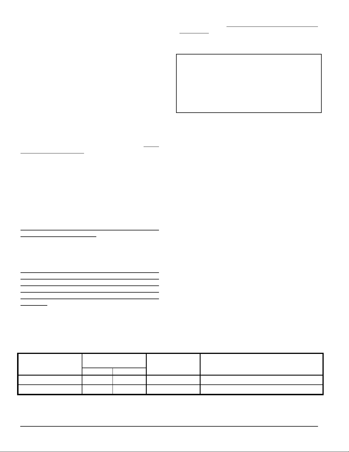
6) CHIMNEY
6.1) Chimney draft
Chimney draft must be strong enough to ensure safe,
reliable operation of your unit.
6.2) Installation
The connecting flue pipe diameter should never
exceed that of the chimney and its horizontal runs
should have a minimum slope of 1/4” (6.4 mm) per
foot (300 mm) of run upward toward the chimney. The
use of a damper in the connecting flue pipe is strictly
prohibited. If more than one pipe are to be connected
to the same chimney, the sectional area of the
chimney must be equal to the total of individual
TABLE 1
Chimney draft
Chimney size
Models
Minimum Maximum
HMD-124 @ 146
HMD-163 @ 179
4
inches (mm)
5 (127) 6 (152) 7 (178) 0.035 (0.9)
6 (152) 8 (203) 7 (178) 0.05 (1.3)
Connecting pipe
inches (mm)
sectional areas. The usage of a draft control is
compulsory. His omission constitutes sufficient
grounds for voiding your warranty.
NOTICE
The formation of condensation on the three
outer sides of an outside chimney is a
possibility with efficient hot water boilers.
Should this happen, a chimney liner or a
“SMH” sidewall venting system should be
installed.
7) BURNER INFORMATIONS
The burner is shipped in a separate box from the
boiler and must be installed following the next steps :
1. Verify the model number on burner box to be
match with the one on the boiler nameplate;
2. Install the nozzle supplied and verify the
electrodes setting;
3. Install the burner on the boiler using supplied nuts
already on the studs. Do not forget the fireproof
gasket supplied with the burner. For the Riello
burners with an adjustable flange, make sure that
the end of the blast tube is flush with the inside
surface of the combustion chamber;
4. Connect the oil pipe(s) to the burner pump;
5. Perform electrical connections in accordance with
the appropriate diagram (See paragraph 4).
Recommended draft
inches (mm) W.C.
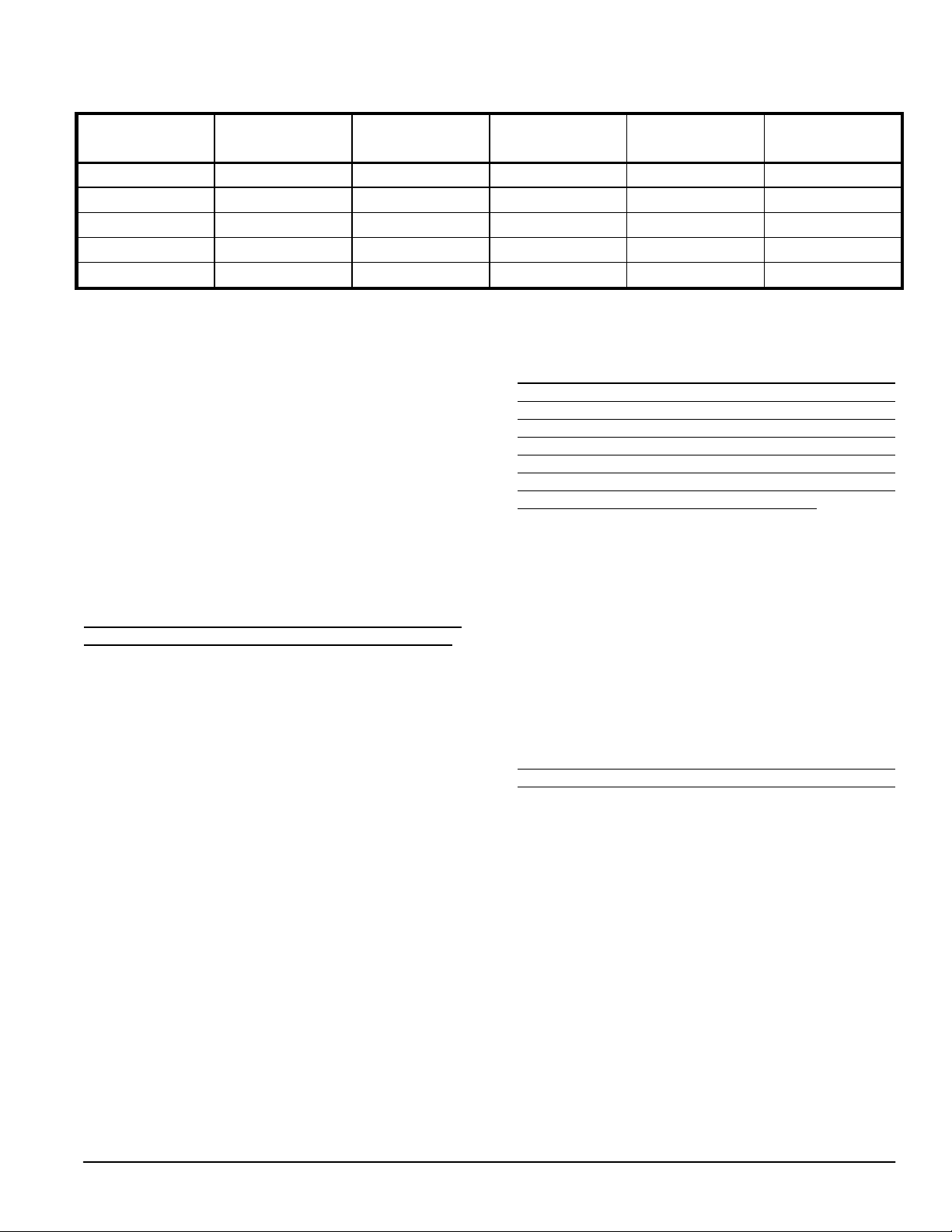
TABLE 2
Model
Capacity
Input
Burner
Nozzle
Pressure
HMD
-
124
124000
1.00 Riello F
-5
0.85-70B 140
HMD
-
135
135000
1.10 Riello F
-5
1.00-70B 125
HMD
-
146
146000
1.20 Riello F
-5
1.00-70B 145
HMD
-
163
163000
1.35 Riello F
-5
1.20-70B 130
HMD
-
179
179000
1.50 Riello F
-5
1.35-70B 125
Burner characteristics - “HMD” boilers
(Btu/hr) (USGPH)
8) COMBUSTION AIR SUPPLY
For a good and reliable operation, every oil heating
system must have an adequate and functional air
supply. If the boiler must be installed in a confined
area, 2 permanent air openings must be provided.
Both openings must be sized by allowing 1 ft2 per U.S.
gallon of oil to burn (240 cm2/l) per hour. One opening
should be located near the ceiling, the other near the
floor.
9) GENERAL PLUMBING
INFORMATIONS
Satisfying operation of your system greatly depend on
your plumbing arrangement. Refer to figures 3 and 4.
In all cases, your installation must include:
a. A pressure reducing valve, set at 12 psi (83 kPa),
installed in the boiler cold water supply;
b. An expansion tank pressurised to 12 psi (83 kPa),
present on the piping;
c. An automatic air vent, to eliminate trapped air in
the boiler;
d. A correctly sized water circulator, installed on the
heating loop;
e. Stop valves and threaded unions, installed on
return and supply boiler pipes.
Always use quality pipe sealant on all threaded
connections and make sure that these connections are
well tightened. Avoid flushing the system when this
boiler is a replacement for an existing one, to limit
oxygen to come in the system.
Delavan (psi)
10) POTABLE HOT WATER SUPPLY
Before attempting to proceed with the potable hot
water supply connections, always check the water
quality to avoid premature scaling, which quickly put
your installation inefficient. Refer to a specialist and
install a water softener if need. Locate the left tapping
to use as the potable cold water inlet. The use of the
thermostatic mixing valve (provided) is a necessity to
get safety and optimum of your installation.
11) THERMOSTAT
The thermostat must be mounted on an inside wall
approximately five feet high on the main floor. The
location should allow the thermostat to detect
temperature variations without exposing it to air
currents and sunrays.
12) DRAFT-REGULATOR
A barometric draft-regulator must be installed on the
connecting pipe between the chimney and the boiler.
It must be located in an easily serviceable location.
Please refer to the installation instructions supplied
with it.
5
 Loading...