

INTERNATIONAL CARBONIC TUACA Installation And Service Manual
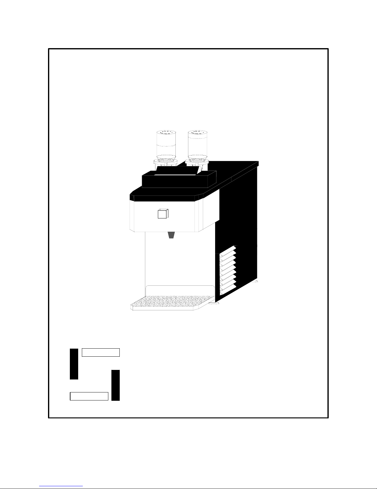
TUACA
PUSH
HERE
Installation and Service Manual
INTERNATIONAL CARBONIC INC.
C
I
16630 Koala Rd.
Adelanto, California 92301
800 854-1177
3/22/05

IMPORTANT: This manual is a guide for installing,
operating, servicing and maintaining this equipment. Refer
to Table of Contents for page location of detailed
information to answer questions that arise during
installation, operating, service and maintenance, or
installation of this equipment.

TABLE OF CONTENTS
PAGE
PREFACE ........................................................................................... 1
CHAPTER 1
GENERAL DESCRIPTION.................................................................. 2
SYSTEM DESCRIPTION .................................................................... 2
DESIGN DATA.................................................................................... 2
THEORY OF OPERATION.................................................................. 3
EXPLODED VIEW............................................................................... 4
EXPLODED VIEW DESCRIPTION ..................................................... 5
ELECTRIC SCHEMATIC..................................................................... 7
CHAPTER II
UNPACKING AND INSPECTION........................................................ 8
SELECTING LOCATION..................................................................... 8
LOCATION RECOMMENDATIONS.................................................... 8
ELECTRICAL REQUIREMENTS......................................................... 8
TUACA UNIT INSTALLATION INSTRUCTIONS................................. 9
FLOW PLAN BOTTLE MOUNT........................................................... 11
CHAPTER III
OPERATORS INSTRUCTIONS.......................................................... 12
DAILY PRE-OPERATION CHECK...................................................... 12
COOLING UNIT MAINTENANCE........................................................ 12
CLEANING NOZZLE........................................................................... 12
CLEANING CONDENSER COIL......................................................... 13
CLEANING AND SANITIZING............................................................. 13
FREQUENTLY ASKED QUESTION.................................................... 14
CHANGING PERISTALTIC PUMP TUBING ....................................... 14
TROUBLE SHOOTING ....................................................................... 15
NOTES................................................................................................ 17

PREFACE
INTERNATIONAL CARBONIC INC. has enjoyed
over 53 years of manufacturing excellence in the
field of carbonation and in the beverage related
industry. We have been located in the Southern
California area since 1952 and have a long and
proud history with quality as our standard and
innovation as our goal. Originally started just
after World War II in Canfield Ohio as Carbonic
Dispensers we enjoyed patents on the first
Sodajet type carbonator. This method of
carbonation instantaneously carbonated the
water to 100% saturation. We developed the
first patented dispensing valve to dispense bulk
beverage with carbonation equal to or in excess
of bottled beverages. A valve with three flavors
and soda was another first. We were the first to
incorporate the total post-mix package; i.e.,
carbonation, refrigeration & the ability to
dispense from one self contained unit. We have
pioneered many such firsts and will continue to
develop advance systems for the future, such as
electronic interrogatable portion controls to
electronic liquid level controls.
We hope you enjoy this product that has been
produced to give many years of trouble free
service. We thank you for your purchase and
hope we may serve you in the future.
1

TUACA CHAPTER I
GENERAL DESCRIPTION
This chapter gives the description, theory of operation, and design data for the TUACA unit.
SYSTEM DESCRIPTION
The TUACA unit is a complete self-contained liquor dispenser which when supplied with TUACA will
dispense a delicious chilled TUACA drink. The unit consists of a cabinet, refrigeration system, modular
peristaltic pumps, and lighted merchandising. The cabinet is housed in an attractive black vinyl and then
decaled with vibrant TUACA Decals. The front plate and drain are formed from attractive grained
stainless steel. The TUACA unit has been designed to fit in the smallest possible space while dispensing
a maximum amount of highly chilled 1oz, servings of TUACA and lime.
Essentially the TUACA unit is designed to plug and play. For proper function the TUACA unit must have
120 volt electrical supply and proper space around unit to allow the refrigeration to breath during
operation. The TUACA unit is designed with a unique lift off drain pan that can be emptied at any
convenient drain outlet.
DESIGN DATA
TUACA
Cabinet:
Height .. ............................................................................................................17 ½
Overall Height w/Merchandiser .........................................................................22 ½
Width ..............................................................................................................11 ¾
Depth ............................................................................................................. 14 7/8
Depth w/Switch Housing....................................................................................17 ¾
Weights:
Shipping.............................................................................................................75 LBS.
Operational weight.............................................................................................69 LBS.
Refrigerant requirement (R-134a)...............................................3.18 ounces
90 grams
Ambient operating temperature.........................................................................40 F to 100 F
Electrical Requirements:
The cooling unit requires a 120 VAC, single phase, 60 Hertz power circuit.
Circuit Ampacity.................................................................................................3.1 Amps
Condensing Unit................................................................................................2.1 Amps
Peristaltic Pump Assembly................................................................................ 1. Amp
REFRIGERATION 1/9 H.P. capillary air-cooled.
2

THEORY OF OPERATION
The TUACA unit was designed to cool and dispense a chilled serving of alcohol
based TUACA. After initial connection to an electrical outlet and installing the
TUACA bottles into the bottle reservoir’s. The unit’s push switch must be
activated until a small portion of TUACA is dispensed. In approximately 15
minutes from the time the unit is electrically activated the unit will dispense a
chilled shot below 32 degrees.
When the Push Switch is pushed the incoming TUACA is routed to a peristaltic
pump, and then through a cooling coil that is positioned next to the refrigeration
evaporator coil. The temperature of the incoming TUACA is at ambient
temperature as it enters the cooling coil. As the incoming TUACA passes
through the cooling coil the heat is removed from the TUACA and chilled to a
temperature acceptable for a quality drink, normally a temperature 7 to 16
degrees is reached. The TUACA is now directed to a dispensing nozzle where
the TUACA is dispensed.
3
 Loading...