

Page 1

Qscan
User’s Guide
V1.4
Page 2

Qscan User’s Guide Version 1.4
SYMBOLS USED IN THIS MANUAL
i
Informational
Warning
!
Page 2
Page 3

!
LASER LIGHT
WARNING
Qscan User’s Guide Version 1.4
CLASS 2 LASER
QSCAN CONTAINS A CLASS 2 LASER.
DO NOT STARE DIRECTLY INTO THE
LASER.
Page 3
Page 4

August 12, 2013
Qscan User’s Guide Version 1.4
Introduction ..................................................................................................................... 5
Features .................................................................................................................. 5
Mounting ................................................................................................................ 6
Depth of Field ........................................................................................................ 7
Wiring ................................................................................................................... 8
Barcode Masking ................................................................................................. 11
Proximity/iClass Masking .................................................................................... 12
Relay .................................................................................................................... 12
Power over Ethernet ............................................................................................. 12
Hid 5352 Emulation ............................................................................................. 13
Arming Loop ........................................................................................................ 13
Leds ...................................................................................................................... 13
Serial Emulation ................................................................................................... 13
Firmware Updates ................................................................................................ 13
Data Flow ............................................................................................................. 14
Programming .................................................................................................................. 15
Symbology Commands ........................................................................................ 16
Barcode Options ................................................................................................... 20
Barcode Masking ................................................................................................. 21
Wiegand Output for Barcode Reading ................................................................. 26
Aamva .................................................................................................................. 31
Emulation Selection and Control ......................................................................... 34
Prox and iClass Programming ............................................................................. 37
Wiegand Output for Prox/iClass .......................................................................... 45
Wiegand Special Outputs ..................................................................................... 47
Digital Inputs and Arming Loop .......................................................................... 51
Serial Settings ...................................................................................................... 51
Hid 5352 Emulation ............................................................................................. 52
Bicolor Led Setup ................................................................................................ 52
Miscellaneous Commands ................................................................................... 53
Serial Commands ........................................................................................................... 54
Firmware Update ........................................................................................................... 56
Serial Emulation ............................................................................................................. 56
Bit Size Table ................................................................................................................. 57
Page 4
Page 5

Qscan User’s Guide Version 1.4
Qscan Features
Built-in proximity or
iclass® reading
Wiegand, aba, 232, or tcp/
udp interface
Fully weatherproofed for outdoor use
Mounting anges on
both sides
Fast 2D scanner reads over 50
types of barcodes,
including PDF and QR codes
Optional POE for easy
powering over a network
Digital inputs for arming loop
control
Reads barcodes from
smartphone displays
Optional 2x16 character display readable in direct sunlight
Extracts elds from Drivers
Licenses
Optional Form C relay
Easily reads damaged and
worn out barcodes
Reads barcodes as far away as
20 inches
Page 5
Page 6

Mounting
Qscan User’s Guide Version 1.4
Qscan can be
mounted using four
screw holes located
on the anges.
You can also mount
using the keyholes on
each ange.
Do not screw through the main body of the
!
Qscan. Mount using the anges only.
MOUNTING
Page 6
Page 7

Barcode Reading
Depth of Field
12
Qscan User’s Guide Version 1.4
READING
20
Figures in inches
16
Qscan can read barcodes up to 20” away depending on the type
of barcode (symbology) and the density of the barcode.
Common reading distances:
PDF 417 driver’s licenses 2.5” - 4.5”
Code39 7.5 mil 2” - 10”
UPC 13 mil 2” - 12”
Data Matrix 15 mil 2” - 12”
Code39 20 mil 1” - 20”
Barcodes do not have to be parallel to the reader.
Qscan can read barcodes tilted as much as 60 ° both
horizontally and vertically.
Qscan will also read barcodes as they are moving. You do not
have to hold the barcode steady within the eld of view.
Page 7
Page 8

Qscan User’s Guide Version 1.4
Wiring
RS232 with a DB9 connector
Green -> Reader Transmit -> DB9 Pin 2
Yellow -> Reader Receive -> DB9 Pin 3
Blue -> Ground -> DB9 Pin 5
DB9 Pin 7
DB9 Pin 8
A short wire (zip cord) extends from the DB9 connector. This wire contains a dc plug
receptacle for connecting the ac adapter.
RS232 with flying leads
Red +12vdc
Blue Ground
Green Reader Tansmit
Yellow Reader Receive
Orange Input 1 (optional)
White Input 2 (optional)
Orange and White are reserved for
digital inputs which can be used for
an arming loop.
WIRING
F2F
Red +12vdc
Blue Ground
Green unused
White unused
Brown F2F*
Orange Green Led / Input 1
Yellow Bicolor Led / Input 2
*Qscan F2F circuitry supports connection to a system with a 5V or
!
12V pullup.
Page 8
Page 9

Qscan User’s Guide Version 1.4
Wiegand
Red +12vdc
Blue Ground
Green Data 0
White Data 1
Orange Green Led / Input 1
Yellow Bicolor Led / Input 2
ABA
Red +12vdc
Blue Ground
Green Clock
White Data
Orange Green Led / Input 1
Yellow Bicolor Led / Input 2
Wiegand output readers can be
reprogrammed to transmit magnetic
stripe emulation (both aba and track
1), wand emulation, or F2F. Input 1
and Input 2 can be used to control
the led’s or used as an arming loop
control.
Wiegand output readers can be
reprogrammed to transmit magnetic
stripe emulation (both aba and track
1), wand emulation, or F2F. Input 1
and Input 2 can be used to control
the led’s or used as an arming loop
control.
WIRING
Wand
Red +12vdc
Blue Ground
Green unused
White Wand
Orange Green Led / Input 1
Yellow Bicolor Led / Input 2
Wiegand output readers can be
reprogrammed to transmit magnetic
stripe emulation (both aba and track
1), wand emulation, or F2F. Input 1
and Input 2 can be used to control
the led’s or used as an arming loop
control.
Page 9
Page 10

Qscan User’s Guide Version 1.4
Ethernet (TCP/UDP)
Ethernet wiring consists of:
3’ cable with an RJ45 connector on it for connecting to the network.
3’ power cable with a barrel receptacle for connecting an ac adaptor.
3’ at cable for optional relay and digital input connections.
Qscan readers with POE may be powered through the Cat5/6 cable from
a POE switch, or powered with the AC Adaptor.
WIRING
Relay Wiring
Relay wiring consists of 3 wires:
Red Common
Green Normally Open
Yellow Normally Closed
Relay connections are independent.
Ethernet Qscans with POE cannot power external equipment using power from
the POE. A separate power supply is required to power the device connected to
the relay.
Page 10
Page 11

Qscan User’s Guide Version 1.4
Barcode Masking
Barcode masking provides a way of extracting certain portions of a barcode for
processing. The masking operations include selecting up to 2 substrings from the
barcode, and also adding prex and sufx characters. You program in a mask when
you do not want to process all of the data from a barcode, but only a portion of it.
When a barcode is read, the reader checks to see if a mask should be applied.
Masks are applied based on the barcode symbology, and length of the barcode.
For example, you can set up a mask to work only on 10 character code39
barcodes. If a code39 barcode is not 10 characters, you can elect to ignore it (don’t
process) or pass the barcode through without masking (pasthru mode). It is also
possible to program a mask to work on all lengths of a specic symbology.
After masking, the barcode data will look like this:
INTRODUCTION
prex character + substring 1 + inter character + substring 2 + sufx
character
The mask needs to include only 1 of the above items.
A total of 10 masks can be programmed in the reader. The masks can be for
different symbologies, or all for the same symbology.
When programming a mask, 3 commands need to be processed by the reader (see
page 21).
For wiegand output Qscans, the masking is performed prior to the wiegand
extractions which create the wiegand output (see page 48).
Page 11
Page 12

Qscan User’s Guide Version 1.4
Proximity & iClass Masking
Proximity and Iclass masking works in a similar way to the barcode masking
explained above. Characters can be inserted into the data and substrings can be
extracted.
There are three programmable masks that can be programmed for prox and
iClass card reading. Each mask is associated with a programmed bit length for a
specic card. When programming the input format (card denition) for a specic
card, the masks (if any) are also programmed in.
This differs somewhat from the barcode masking. With the barcode masking you
program the masks independently of the barcode symbologies, and the masks
are triggered by both symbology and length. With the prox/iClass masking, the
masks are triggered by the length (bit length) only.
Relay
The Relay (optional) allows you to control external equipment, such as a door
or indicator. It can be activated and deactivated by sending serial commands
to the reader. The maximum allowable relay time is 99 seconds, and maximum
allowable power that can be pushed through the relay is 500ma, 30VDC.
The relay is a Form-C with common, normally open, and normally closed
connections.
INTRODUCTION
Qscans can optionally be ordered with Power over Ethnernet. With Power over
Ethernet, you do not need a separate power supply or ac adapter.
Power over Ethernet
Page 12
Page 13

Qscan User’s Guide Version 1.4
Hid 5352 Emulation
Qscans with an rs232 interface can be programmed to simulate the output from
an Hid 5352 reader, using the 37 bit format.
Arming Loop
Either of the 2 digital inputs in the Qscan can be programmed to operate as
an armed loop. In the armed loop mode, if the arming loop is not ativated, the
Qscan will not transmit any data. Arming loops are typically used in parking
applications. If there is no car present, the arming loop will not be active,
therefore all barcode reads will be ignored.
Leds
There are two leds on the Qscan. The led to the left is a bi-color led, and can be
programmed to operate in one of three modes - off to red, off to green, red to
green. The right led is a green led only. Typically, Qscans with a wiegand interface
will be connected to a device (a controller) which will control one or both of the
leds. For Qscans with a serial interface, the leds will be controlled by sending serial
commands to the reader.
INTRODUCTION
Qscans with an emulations-style interface (wiegand, mag, f2f) can be wired in a
way which allows serial communications. You can go into this operating mode to
send commands to the Qscan for programming, and also for rmware updates.
Serial Emulation/Firmware Updates
Page 13
Page 14

Qscan User’s Guide Version 1.4
Data Flow
The following explains the data ow in the reader for a better understanding of how
data is processed.
Barcode:
Read Barcode
If symbology (barcode type) not allowed - ignore
If pdf417, check for driver’s license parsing and parse if required.
If masking is on, mask the barcode according to the mask specications.
If rs232, tcp/ip, f2f, aba, or wand output - transmit data (nished)
INTRODUCTION
If wiegand output - generate the wiegand output data (bits). If successful, transmit
the wiegand data (nished). If not sucessessful, ignore data.
Prox/iClass:
Read Card
If a wiegand output reader, and passthru is turned on - pass the prox/iClass data to
the wiegand output undisturbed.
If card bit length matches a dened format, extract the numbers for each dened
eld. If it does not match a dened format - ignore. If any of the eld descriptions
cause an overow to occur - ignore.
If masking is on, mask the resulting data according to the format.
If rs232, tcp/ip, f2f, aba, or wand output - transmit data (nished)
If wiegand output - generate the wiegand output data (bits). If successful, transmit
the wiegand data (nished). If not sucessessful, ignore data.
Page 14
Page 15

Qscan User’s Guide Version 1.4
Programming
Qscans can be programmed in two ways:
1) Scanning control barcodes.
2) Sending commands to the reader serially.
Scanning Control Barcodes:
Make a Code39 barcode starting with %U followed by the command and
scan the barcode. Note that control card processing can be turned off by either a serial
command or a control barcode.
Serial commands:
PROGRAMMING
Send the command to the reader serially by making a direct connection to the reader
and then sending the command, followed by a carriage return (hex 0D). If using a
terminal emulation program, the 0D is sent by hitting the enter key.
Qscan readers that have a wiegand output can be connected to a serial port for
i
sending commands. See page 55 for further information.
Command Format:
All programming commands are detailed in the following format:
Command Description
Command Format (spaces for clarity only, do not use them )
parameter meaning values values
Special Instructions
Page 15
Page 16
Symbology Setup 1
X001 a b c d e f g h
Qscan User’s Guide Version 1.4
a Code 39 0=off 1=on
b Code 39 full ascii 0=off 1=on
c Code 39 trioptic 0=off 1=on
d Code 39 to code 32 0=no 1=yes
e Code 39 check digit 0=off 1=on
f Upc A 0=off 1=on
g Upc E 0=off 1=on
h Ean8 / Jan8 0=off 1=on
Use this command to turn the listed symbologies and features on or off.
!
If code39 full ascii is turned on, the reader will no longer
respond to control barcodes. Programming can be achieved using
serial commands only.
PROGRAMMING
BARCODE
Symbology Setup 2
X002 a b c d e f g h
a Ean13 / Jan 13 0=off 1=on
b Code 128 0=off 1=on
c Gs1 0=off 1=on
d Ibst 128 0=off 1=on
e Code 93 0=off 1=on
f Code 11 0=off 1=on
g Code 11 check digit 0=off 1=on
h Interleaved 2 of 5 0=off 1=on
Use this command to turn the listed symbologies and features on or off.
Page 16
Page 17
Qscan User’s Guide Version 1.4
Symbology Setup 3
X003 a b c d e f g h
a I 2 of 5 check digit 0=off 1=on
b 2 of 5 0=off 1=on
c Codabar 0=off 1=on
d Codabar clsi 0=off 1=on
e Msi / Plessy 0=off 1=on
PROGRAMMING
f Chinese 2 of 5 0=off 1=on
g Matrix 2 of 5 0=off 1=on
h M 2 of 5 check digit 0=off 1=on
Use this command to turn the listed symbologies and features on or off.
Symbology Setup 4
X004 a b c d e f g h
a Korean 3 of 5 0=off 1=on
b Postnet 0=off 1=on
c Planet 0=off 1=on
d Postal 0=off 1=on
e Japan Post 0=off 1=on
BARCODE
f Australia Post 0=off 1=on
g Kix 0=off 1=on
h Usps Onecode 0=off 1=on
Use this command to turn the listed symbologies and features on or off.
Page 17
Page 18

Qscan User’s Guide Version 1.4
Symbology Setup 5
X005 a b c d e f g h
a UPU cs 0=off 1=on
b GS1 14 0=off 1=on
c Composite cc 0=off 1=on
d Composite ccab 0=off 1=on
e Composite tlc39 0=off 1=on
PROGRAMMING
f Pdf417 (2d) 0=off 1=on
g Micropdf (2d) 0=off 1=on
h Datamatrix (2d) 0=off 1=on
Use this command to turn the listed symbologies and features on or off.
Symbology Setup 6
X006 a b c d e f g h
a Datamatrix inverse (2d) 0=off 1=on
b unused always 0
c Maxicode (2d) 0=off 1=on
d QR (2d) 0=off 1=on
e QR inverse (2d) 0=off 1=on
BARCODE
f Micro QR (2d) 0=off 1=on
g Aztec (2d) 0=off 1=on
h Aztec inverse (2d) 0=off 1=on
Use this command to turn the listed symbologies and features on or off.
Page 18
Page 19

Qscan User’s Guide Version 1.4
Symbology Setup 7
X007 a b c d e f g h
a Bookland 0=off 1=on
b Postbar 0=off 1=on
c Macro Pdf (2d) 0=off 1=on
d UCC coupon 0=off 1=on
e unused always 0
PROGRAMMING
f unused always 0
g unused always 0
h unused always 0
Use this command to turn the listed symbologies and features on or off.
Length Settings for 2 of 5 Symbologies
X040 aa bb cc dd ee ff
aa I 2 of 5 length 1 2 digit length 00=any length
bb I 2 of 5 length 2 2 digit length 00=any length
cc M 2 of 5 length 1 2 digit length 00=any length
dd M 2 of 5 length 2 2 digit length 00=any length
ee D 2 of 5 length 1 2 digit length 00=any length
BARCODE
ff D 2 of 5 length 2 2 digit length 00=any length
Because of the structure of 2 of 5 barcodes, it is possible that reading
only part of the barcode will result in a valid decode, with undesired
results. To suppress this problem, it is best to use check digits with 2 of
5 symbologies (if available) or restrict the lengths for these barcodes so
that partial decodes cannot occur. You can program up to two different
lengths for each of the supported 2 of 5 symbologies. If you prefer to
leave it wide open, then you can set the lengths to 00.
Page 19
Page 20

Qscan User’s Guide Version 1.4
General Barcode Options
X012 a m k c
a alpha delete 0=off 1=on
m masking 0=off 1=on
k Kronos mode 0=off 1=mode1, 2=mode2
c Usic/Cac 0=off 0=off, 1=on, 2=required
PROGRAMMING
Turn on Alpha Delete to delete any alpha characters from the barcode.
This is useful when a numeric only output is required such as wiegand.
Masking allows you to mask out information from the barcode, leaving
only that portion of the barcode that you wish to process.
Kronos mode autodiscriminates Kronos cards (17 digit code 39 and 18
digit I 2of5). Kronos mode 1 extracts the rst 2 digits of the site code
and the lowest 5 digits of the ID. Kronos mode 2 forces a site code of 0,
and extracts the lowest 9 digits of the ID.
Usic/Cac sets the options for processing DOD Usic cards and Cac cards.
Set to 0, Usic and Cac barcodes are processed like any other barcode. If
set to 1, Usic and Cac cards are processed according to the parameters
that you have programmed. If set to 2, all barcodes are ignored unless
they meet the characteristics for Usic and Cac cards.
BARCODE
Page 20
Page 21

Qscan User’s Guide Version 1.4
Barcode Masking
X010 xx ctt llnn r
X011 xx ppp sss1 b lll
X012 xx iii sss2 y ll2 sss
xx mask number 01 thru 10
ctt barcode type see list on next page
llnn barcode length 0000=all lengths max=1500
r passthru 0=off 1=on
ppp prex character 000=none
sss1 start position 1 0000=none
b backwards 0=no 1=yes
lll extraction length 000=all max=200
iii inter character 000=none
sss2 start position 2 0000=none
y backwards 0=no 1=yes
ll2 extraction length 000=all max=200
sss sufx character 000=none
PROGRAMMING
BARCODE MASKING
All 3 commands need to be processed by the reader to properly set a
mask.
Masking must be explicitly turned on with the X012 command on page
xxx.
The value for prex, sufx, and inter character is represented in
decimal ascii form (041 = “A”, 039 = “9”).
If b (or y) is set to a 1, then the extracted data starts at a position
“start position” relative to the end of the barcode.
See the following pages for a detailed explanation and examples.
If needed, all masks can be cleared with one command. See the X014
command on page 25.
Page 21
Page 22

Barcode Masking Symbology Codes
These are the codes used for the ctt parameter
2 of 5 004
Aus Post 035
Aztec 045
Bookland 022
Codabar 002
Code 11 012
Code 39 001
Code 39 full ascii 019
Code 93 007
Code 128 003
Datamatrix 027
Dutch Post (Kix) 036
Ean8 / Jan8 010
Ean13 / Jan13 011
Gs1 015
Gs1 databar 048
Interleaved 2 of 5 006
Japan Post 034
Maxicode 037
Micro Pdf 026
Micro QR 044
Msi/Plessy 014
Pdf417 017
Planet 031
Postbar 038
Postnet 030
QR 028
UK Post 039
UpcA 008
UpcE 009
Usps Onedec 052
Qscan User’s Guide Version 1.4
PROGRAMMING
BARCODE MASKING
Masking can be programmed only for the barcode types listed above.
Page 22
Page 23

Qscan User’s Guide Version 1.4
Notes on using the Barcode Masking Commands:
If (“ctt”) matches the type of barcode read, and the length of the barcode matches
(“llnn”) then the barcode is masked according to the programmed parameters. If the
length (“llnn”) is set to 0000, then the mask will apply to all barcodes of the specic
symbology specied by (“ctt”).
If any of the parameters causes the mask to be invalid, the barcode is not processed
and the reader acts as if it has read a disallowed barcode (bad beep indicator). For
example, attempting to extract 10 digits starting at position 5, on a barcode that is
only 12 digits in length, is invalid.
PROGRAMMING
The pasthru option allows you to specify what to do when a barcode that is read
matches the selected barcode symbology (“ctt”) but does not match the required
length (“llnn”). In this case, you have the option of disallowing the barcode (option 0),
or passing the barcode through so that the other masks may be tested.
An example would be where you want to restrict barcode reading to two different
lengths of code 39 barcodes, namely 10 digits and 15 digits. You will set up the rst
mask to operate on a length of 10, with the passthru option on (“r=1”). Code 39
barcodes with a length other than 10 will not be processed by this mask, put passed
through to the next (2nd) mask. Set the 2nd mask to operate on code 39 barcodes
with a length of 15, with no passthru (“r=0”). In this case, 10 digit code 39 barcodes
are handled by mask 1, 15 digit code 39 barcodes are handled by mask 2, and all other
code 39 barcodes are ignored by the reader.
The start positions (“sss1,sss2”) are the positions in the barcode where the data
extraction starts. This position can be relative to the beginning of the barcode
(b=0 or y=0), or the end of the barcode (“b=1 or y=1”). If you want to take the last
“x” characters in the barcode, set the backwards indicator (“b or y”) to a 1.
The wiegand processing routines contain their own form of masking.
If processing a barcode for wiegand output, the programmable
masking within the weigand commands may be sufcient. Using
i
the general masking commands may not be necessary for simplied
masking (see page 48).
BARCODE MASKING
Masking Examples:
For code 39 barcodes of any length , take the rst 5 positions only:
X010 01 001 0000 0
X011 01 000 0001 0 005
X012 01 000 0000 0 000 000
Page 23
Page 24

Qscan User’s Guide Version 1.4
For code 39 barcodes of any length , take the rst 5 positions only but prex with a “A”:
X010 01 001 0000 0
X011 01 065 0001 0 005
X012 01 000 0000 0 000 000
For code 39 barcodes of length 10, take the last 5 characters. For all other code 39 barcodes,
pass thru and do not mask:
X010 01 001 0010 1
X011 01 000 0005 1 005
X012 01 000 0000 0 000 000
For code 39 barcodes of any length, take all characters after position 4:
X010 01 001 0000 0
X011 01 000 0005 0 000
X012 01 000 0000 0 000 000
For code 39 barcodes of length 10, take the last 5 characters. For code 39 barcodes of length
15, take the last 10 characters. Ignore all other code 39 barcodes (don’t pass thru):
X010 01 001 0010 1
X011 01 000 0005 1 005
X012 01 000 0000 0 000 000
X010 02 001 0015 0
X011 02 000 0010 1 010
X012 02 000 0000 0 000 000
PROGRAMMING
BARCODE MASKING
Page 24
Page 25

Qscan User’s Guide Version 1.4
Clear All Barcode Masks
X014 b p
b set to any value
p set to 0
Use this commmand to clear all of the programmed masks for
barcodes.
PROGRAMMING
BARCODE MASKING
Page 25
Page 26
Qscan User’s Guide Version 1.4
Wiegand Output Format # 1 (for barcode data)
X015 a mmmm ssss sd bbbb
X016 bd iiii id ss bb ii
X017 x y z lpp rpp h i j k
a active indicator 0=inactive 1=active
mmmm barcode length 0-1500 0000=any
ssss site code start 0000=no site
sd site code digits 00=remaining
bbbb id start 0000=no id
bd id digits 00=remaining
iiii issue code start 0000=no issue
id issue code digits 00=remaining
ss site code bits 00=none
bb id code bits 00=none
ii issue code bits 00=none
x,y,z backwards indicators 0=off (msb) 1=on (lsb)
lpp left parity bits 000=none
rpp right parity bits 000=none
h,i,j eld numbers for xmit 1=site,2=id 3=issue,0=none
k site override 0=no 1=yes
PROGRAMMING
BARCODE -> WIEGAND OUT
see comments on the following pages.
Wiegand Output Format # 2 (for barcode data)
X019 a mmmm ssss sd bbbb
X020 bd iiii id ss bb ii
X021 x y z lpp rpp h i j k
see Wiegand Output Format # 1 for parameter descriptions
Page 26
Page 27

Qscan User’s Guide Version 1.4
Programming the Wiegand Output Formats (barcode)
The standard wiegand output permits the transmission of wiegand formats of up to
194 bits, containing up to three elds (site, id, and issue). Each eld can contain up
to 64 bits each. Two parity bits may also be programmed.
Different wiegand output formats can be dened. The format that is used is
dependent on the data which is read by the reader. There are 2 denable formats
for barcode data.
For barcode data, the format that is used depends on the nal length of the barcode
data after masking. You can specify a barcode length to be matched for each of the
formats. If the barcode length mathes the format’s length, then that format is used.
A length of 0 can be used to dene one format as the default format to be used for
all barcode reads. Note that a format needs to be active (“a=1”) to be recognized.
Each format contains the denitions of how the data is to be transmitted. These
denitions include:
The number of bits to be used for the site, id, and issue elds
(“ss,bb,ii”)
A setting to organize each eld as msb or lsb (“x,y,z”)
PROGRAMMING
BARCODE -> WIEGAND OUT
The location(s) in the barcode where the data for each eld is to be
extracted (“ssss,bbbb,iiii”)
The number of characters to use for each of of those elds (“sd,bd,id”)
Which elds are to be included in the output format (“h,i,j”)
Number of bits to be used for left and right parity (“lpp,rpp”)
An indicator to force an override of the site code (“k”).
An example of programming a standard 26 bit wiegand output follows. The format
will be set up to work on all barcodes that are read, regardless of the length of the
barcode. The rst 3 digits of the barcode will be used for the site code, and the next
5 digits will be used for the id. No issue code will be present:
Page 27
Page 28

Qscan User’s Guide Version 1.4
X015 1 0000 0001 03 0004
X016 05 0000 00 08 16 00
X017 0 0 0 012 012 1 2 0 0
An example of the same format, this time restricting this format for use only with 10
character barcodes:
X015 1 0010 0001 03 0004
X016 05 0000 00 08 16 00
X017 0 0 0 012 012 1 2 0 0
PROGRAMMING
An example of the same format, this time selecting 0 site code digits, which has the
effect of forcing the site code to 0 (because the format still has 8 bits specied for
the site code), and taking the rst 5 digits of the barcode:
X015 1 0000 0000 00 0000
X016 05 0000 00 08 16 00
X017 0 0 0 012 012 1 2 0 0
An example of a 50 bit format, using 32 bits for the id, 8 for the site, 8 for the issue
code, and 2 parity bits. The site code will be taken from the rst 3 digits of the
barcode. The next 5 digits will be used for the id, and the next digit for the issue
code. The rst bit of the output will be a left parity bit calculated from the following
24 bits. The last bit (bit 50) will be a parity bit calculated from the preceding 24 bits:
X015 1 0000 0001 03 0004
X016 05 0009 01 08 16 18
X017 0 0 0 024 024 1 2 3 0
Command Notes:
BARCODE -> WIEGAND OUT
If site code start (“ssss”) is 0000, then no site code is extracted from the barcode
data. You may still include bits in the output format for the site code, except the
site code data will not come from the barcode. It will default to 0, unless you have
programmed a site override.
If site code digits (“sd”) is set to 00, then all remaining digits in the barcode are
used for the site code.
If id start (“bbbb”) is 0000, then no id is extracted from the barcode data. You may
Page 28
Page 29

Qscan User’s Guide Version 1.4
still include bits in the output format for the id, except the id will not come from the
barcode. It will default to 0.
If id digits (“bd”) is set to 00, then all remaining digits in the barcode are used for
the id.
If issue code start (“iiii”) is 0000, then no issue code is extracted from the barcode
data. You may still include bits in the output format for the issue code, except the
issue code data will not come from the barcode. It will default to 0.
If issue code digits (“id”) is set to 00, then all remaining digits in the barcode are
used for the issue code.
If site code bits (“ss”) is set to 00, then there will be no site bits in the output.
If id bits (“bb”) is set to 00, then there will be no id bits in the output.
If issue code bits (“ii”) is set to 00, then there will be no issue bits in the output.
PROGRAMMING BARCODE -> WIEGAND OUT
If the lsb indicator (“x,y,z”) is on for any specic eld, then the output data for
that eld is set up using the least signicant bit rst. The default for most wiegand
formats is to use msb (most signicant bit rst).
The number of parity bits used for left parity is set by (“lpp”). If set to 000 then
there is no left parity bit.
The number of parity bits used for right parity is set by (“rpp”). If set to 000 then
there is no right parity bit.
Parity bits are calculated using sequential bits starting at the beginning of the output
bitstream for left parity, and starting at the end for right parity. Parity is even on the
left and odd on the right, unless changed using the X026 or X027 commands.
You do not have to include all of the elds (site, id, issue) in the wiegand output data
stream. The (“h,i,j”) parameters dene which elds are to be output and in which
order. A 1 refers to the site code eld, 2 refers to the id eld, 3 refers to the issue
code eld, and 0 means no eld. To generate a wiegand output stream with only an
id eld, the values will be 2 0 0. To generate a stream with site and id, the values will
be 1 2 0. To generate a eld with id rst, then site, then issue, it would be 2 1 3.
A site override can be programmed using the X018 and X022 commands. To turn site
override processing on, (“k”) must be set to a 1.
Page 29
Page 30
Qscan User’s Guide Version 1.4
Wiegand Format # 1 (barcode) Site Override
X018 ssss
ssss site override hexadecimal
This command sets the site override value for wiegand format # 1 for
barcode data.
This command species the site override value for wiegand format # 1 for use
with barcode data. If the site override option is on, then the site eld data is
replaced with the (“ssss”) value. (“ssss”) is programmed as 4 hexadecimal
characters, representing 16 bits. If the site eld is larger than 16 bits, the
(“ssss”) data will be right justied in a zero lled eld. If the site eld is smaller
than 16 bits, then the lowest bits in the override value are used up to the size
of the site eld.
Wiegand Format # 2 (barcode) Site Override
X022 ssss
PROGRAMMING BARCODE -> WIEGAND OUT
ssss site override hexadecimal
This command sets the site override value for wiegand format # 2 for
barcode data.
Page 30
Page 31

Qscan User’s Guide Version 1.4
Aamva Control
X032 a b
a Aamva required 0=no 1=yes
b Field Masking 0=off 1=on
Aamva is the standard for drivers licenses in the US and Canada. Turn
the Aamva Required option on (a=1) to restrict the reading of pdf417
barcodes to Aamva only. If on, no pdf417 barcodes will be read unless
they meet the Aamva format. This setting has no effect on other barcode
symbologies.
When Aamva eld masking is on (b=1) , each eld from the Aamva
drivers license is parsed. You can then use the Aamva eld commands to
concatenate elds together.
PROGRAMMING
AAMVA
AAMVA
Aamva Field Commands
X033 ff ll ttt ff ll ttt
X034 ff ll ttt ff ll ttt
X035 ff ll ttt ff ll ttt
X036 ff ll ttt ff ll ttt
X037 ff ll ttt ff ll ttt
Extractions 1-2
Extractions 3-4
Extractions 5-6
Extractions 7-8
Extractions 9-10
ff Field to extract see table next page 000=none
ll Field length 1-20 0=actual
ttt terminator character 000=none
These commands select the elds which will be extracted and processed.
Fields are extracted in the order of extraction # ( 1 rst, 10 last). If
the eld length is set to non 0, then if the eld is larger than the value
specied, it is truncated. If smaller, it is left justied and blank lled.
The terminator character (if non 0) is appended to the eld value. ttt is
entered as a 3-digit decimal ascii value (065=”A”, 053=”5”).
Page 31
Page 32

Qscan User’s Guide Version 1.4
Aamva Field Numbers
These are the codes used for the ff parameter
00 Ignore, no extraction
01 License number
02 Birthdate
03 Expiration date
04 Last name
05 First name
06 Name sufx
07 Street address
08 City
09 State / Province
10 Zip code
11 Issue date
12 Sex
13 Name (version 1)
PROGRAMMING
AAMVA
Version 1.0 Aamva licenses do not have separate elds for rst and
last names. Only one eld is used (eld # 13 above) which includes
both the last and rst names. Qscan automatically parses the Version
1.0 “name” eld into a rst and last name, however the parsing is
contingent upon the eld being encoded properly on the license. If
you will be reading only version 1.0 licenses, then the Name (eld
#13) eld can be used.
Clear Aamva Fields
X038 1
Use this commmand to clear all of the programmed elds
Page 32
Page 33

Aamva Programming Example:
Qscan User’s Guide Version 1.4
Extract license # and state. Pad the license # to a 20 character eld, insert
a tab character between the two elds, add a carriage return at the end.
X033 01 20 008 09 00 013
X034 00 00 000 00 00 000
X035 00 00 000 00 00 000
X036 00 00 000 00 00 000
X037 00 00 000 00 00 000
PROGRAMMING
AAMVA
Page 33
Page 34

Qscan User’s Guide Version 1.4
Selection of Output Style
X023 a
a Type of Output 1=wiegand, wieaba, alphawie
2=magstripe, aba, f2f
3=wand emulation
This command is used to program the type of “emulation” output sent by
the reader. Qscans with a “wiegand” ordering code can be reprogrammed
to output any of the above formats.
PROGRAMMING
EMULATIONS
Mag Emulation Control (rmware prior to 3/29/13)
X024 c d t f b pp ss
c cstart 0=off 1=on
d neuron mode 0=off 1=on
t track emulation 1=track 1 2=track 2 (aba)
f f2f 0=no 1=yes
b time between pulses 1 - 5 ms default=1 (1ms)
pp pulse time * 50us 1 - 5 *50us default=02 (100us)
ss data settle time *10us 1 - 2 *10us default=02 (20us)
“c” applies to track 2 (aba) output only. When on, a C start sentinel is sent
instead of a B start sentinel. Set “d” to 1 if your system requires data to
go up at the same time as the clock signal.
To transmit in f2f format, “f” must be set to 1.
!
!
Qscan F2F circuitry supports connection to a system with a 5V or
12V pullup.
Page 34
Page 35

Qscan User’s Guide Version 1.4
Mag Emulation Control (rmware after 3/29/13)
X024 c d t f b pp ss l yy
c cstart 0=off 1=on
d neuron mode 0=off 1=on
t track emulation 1=track 1 2=track 2 (aba)
f f2f 0=no 1=yes
b time between pulses 1 - 5 ms default=1 (1ms)
pp pulse time * 50us 1 - 5 *50us default=02 (100us)
ss data settle time *10us 1 - 2 *10us default=02 (20us)
l lead/trail zero bits 0=yes, 1=no default=0
zz right justify zero ll zz=# digits 00=no justify
This command is the same as the prior command except for the addition
of the l and zz parameters.
Magnetic stripe data is typically preceeded with a number of 0 bits
and appended witha number of 0 bits, for synchronization. The Qscan
default is to send 10 zero bits before and after the data stream. These 0
bits can be turned off with the (“l”) parameter.
PROGRAMMING
EMULATIONS
Some controllers and software systems require xed length magnetic
stipe data. The (“zz”) parameter can be set to right justify the aba data
into a data eld (“zz”) characters long. The data is zero lled. To turn
off this option, set (“zz”) to 00.
Page 35
Page 36

Qscan User’s Guide Version 1.4
Wiegand Emulation Control
X025 o b p
o output style 0=standard 1=wieaba, 2=alphawie
b time between pulses 1 - 5 ms default=1 (1ms)
p pulse time * 50us 1 - 5 default=2 (100us)
This command sets the general output parameters for wiegand output.
Wiegand Left Parity Style
X026 s o
PROGRAMMING
PROGRAMMING EMULATIONS
EMULATIONS
s Parity Style 0=even, 1=odd default=even
o unused must be 0
This command sets the left parity for all wiegand outputs to even or odd.
Wiegand Right Parity Style
X027 s o
s Parity Style 0=even, 1=odd default=even
o unused must be 0
This command sets the right parity for all wiegand outputs to even or odd.
Page 36
Page 37

Qscan User’s Guide Version 1.4
Proximity and iClass General Settings
X047 c m b p s
c card style 1=wiegand 2=aba
m masking 0=off 1=on
b good read beep 0=off 1=on
p parity check (26 & 28) 0=off 1=on
s passthru 0=off 1=on
This command sets the general settings for proximity and iClass input.
If passthru (“s”) is turned on, and the output mode is set to wiegand,
then no interpretation of the prox or iClass data is done. The card data is
transmitted exactly as it is on the card.
PROGRAMMING
PROX ICLASS
Proximity and iClass Input, Format # 1, Part 1*
X048 bbb sss sl b bss bl x
bbb # card bits max=250
sss site start bit 000=no site
sl # bits for site code 00=none
b site is lsb 0=off 1=site is lsb
bss id start bit 000=no id
bl # bits for id 00=none
x id is lsb 0=off 1=id is lsb
This command is the rst part of a 2 part command, for setting up an
input proximity or iClass format.
* added to rmware 5/22/13
Page 37
Page 38
Qscan User’s Guide Version 1.4
Proximity and iClass Input, Format # 1, Part 2*
X049 iss il b sc ic uc
iss issue code start bit max=250
il # bits for issue code 000=no issue
b issue code is lsb 0=off 1=issue is lsb
sc site characters 00=none max=20
ic id characters 00=none max=20
uc issue characters 00=none max=20
This command is the second part of a 2 part command, for setting up an
input proximity or iClass format.
* added to rmware 5/22/13
PROGRAMMING
PROX ICLASS
Proximity and iClass Input, Format # 2, Part 1*
X050 bbb sss sl b bss bl x
bbb # card bits max=250
sss site start bit 000=no site
sl # bits for site code 00=none
b site is lsb 0=off 1=site is lsb
bss id start bit 000=no id
bl # bits for id 00=none
x id is lsb 0=off 1=id is lsb
This command is the rst part of a 2 part command, for setting up an
input proximity or iClass format.
* added to rmware 5/22/13
Page 38
Page 39

Qscan User’s Guide Version 1.4
Proximity and iClass Input, Format # 2, Part 2*
X051 iss il b sc ic uc
iss issue code start bit max=250
il # bits for issue code 000=no issue
b issue code is lsb 0=off 1=issue is lsb
sc site characters 00=none max=20
ic id characters 00=none max=20
uc issue characters 00=none max=20
This command is the second part of a 2 part command, for setting up an
input proximity or iClass format.
* added to rmware 5/22/13
PROGRAMMING
PROX ICLASS
Proximity and iClass Input, Format # 3, Part 1*
X052 bbb sss sl b bss bl x
bbb # card bits max=250
sss site start bit 000=no site
sl # bits for site code 00=none
b site is lsb 0=off 1=site is lsb
bss id start bit 000=no id
bl # bits for id 00=none
x id is lsb 0=off 1=id is lsb
This command is the rst part of a 2 part command, for setting up an
input proximity or iClass format.
* added to rmware 5/22/13
Page 39
Page 40

Qscan User’s Guide Version 1.4
Proximity and iClass Input, Format # 3, Part 2*
X053 iss il b sc ic uc
iss issue code start bit max=250
il # bits for issue code 000=no issue
b issue code is lsb 0=off 1=issue is lsb
sc site characters 00=none max=20
ic id characters 00=none max=20
uc issue characters 00=none max=20
This command is the second part of a 2 part command, for setting up an
input proximity or iClass format.
* added to rmware 5/22/13
PROGRAMMING
PROX ICLASS
Proximity and iClass Input, Format # 1 Mask, Part 1*
X054 p1 ll1 p2 ll2
p1 start position 00=ll1 is a constant
ll1 length or constant
p2 start position 00=ll2 is a constant
ll2 length or constant
p1 and p2 refer to the start position in the data to start an extraction of
data. The data is extracted for a length of ll1,ll2. If p1 or p2 is 00, then
ll1 or ll2 refers to a constant value which will be inserted into the data
value. The constant value is a 3-digit ascii decimal value of the character
to insert (“A” = 065). If both p1 and ll1 (or p2 and ll2) are 0, then that
portion of the mask is ignored. See the examples at the end of this
section.
Note this mask applies only to prox/iClass cards with a bit length dened
by prox/iClass format # 1.
* added to rmware 5/22/13
Page 40
Page 41
Qscan User’s Guide Version 1.4
Proximity and iClass Input, Format # 1 Mask, Part 2*
X055 p3 ll3 p4 ll4 p5 ll5
p3 start position 00=ll3 is a constant
ll3 length or constant
p4 start position 00=ll4 is a constant
ll4 length or constant
p5 start position 00=ll5 is a constant
ll5 length or constant
All parameters have the same usage as the prior command.
* added to rmware 5/22/13
PROGRAMMING
PROX ICLASS
Proximity and iClass Input, Format # 2 Mask, Part 1*
X056 p1 ll1 p2 ll2
p1 start position 00=ll1 is a constant
ll1 length or constant
p2 start position 00=ll2 is a constant
ll2 length or constant
p1 and p2 refer to the start position in the data to start an extraction of
data. The data is extracted for a length of ll1,ll2. If p1 or p2 is 00, then
ll1 or ll2 refers to a constant value which will be inserted into the data
value. The constant value is a 3-digit ascii decimal value of the character
to insert (“A” = 065). If both p1 and ll1 (or p2 and ll2) are 0, then that
portion of the mask is ignored. See the examples at the end of this
section.
Note this mask applies only to prox/iClass cards with a bit length dened
by prox/iClass format # 2.
* added to rmware 5/22/13
Page 41
Page 42
Qscan User’s Guide Version 1.4
Proximity and iClass Input, Format # 2 Mask, Part 2*
X057 p3 ll3 p4 ll4 p5 ll5
p3 start position 00=ll3 is a constant
ll3 length or constant
p4 start position 00=ll4 is a constant
ll4 length or constant
p5 start position 00=ll5 is a constant
ll5 length or constant
All parameters have the same usage as the prior command.
* added to rmware 5/22/13
PROGRAMMING
PROX ICLASS
Proximity and iClass Input, Format # 3 Mask, Part 1*
X058 p1 ll1 p2 ll2
p1 start position 00=ll1 is a constant
ll1 length or constant
p2 start position 00=ll2 is a constant
ll2 length or constant
p1 and p2 refer to the start position in the data to start an extraction of
data. The data is extracted for a length of ll1,ll2. If p1 or p2 is 00, then
ll1 or ll2 refers to a constant value which will be inserted into the data
value. The constant value is a 3-digit ascii decimal value of the character
to insert (“A” = 065). If both p1 and ll1 (or p2 and ll2) are 0, then that
portion of the mask is ignored. See the examples at the end of this
section.
Note this mask applies only to prox/iClass cards with a bit length dened
by prox/iClass format # 3.
* added to rmware 5/22/13
Page 42
Page 43
Qscan User’s Guide Version 1.4
Proximity and iClass Input, Format # 3 Mask, Part 2*
X059 p3 ll3 p4 ll4 p5 ll5
p3 start position 00=ll3 is a constant
ll3 length or constant
p4 start position 00=ll4 is a constant
ll4 length or constant
p5 start position 00=ll5 is a constant
ll5 length or constant
All parameters have the same usage as the prior command.
* added to rmware 5/22/13
PROGRAMMING
PROX ICLASS
Programming for Prox and iClass reading
Qscan can read proximity and iClass cards up to 250 bits in length. Prox and
iClass card data can be passed through directly to the output (if the Qscan
has wiegand output), or processed directly by the Qscan. If processed directly
by the Qscan, the card format(s) need to be programmed into the Qscan so
that it can correctly read the card. This involves programming the starting bit
location and number of bits for each eld to be processed from the card, and
the number of digits to reserve for each of the elds.
Three prox/iClass formats can be programmed into the Qscan. Each format
is identied by the number of bits dened in the format. When a card is read
that matches the bit count dened in the format - that format is used by
the Qscan to further process the data. When processing the format, Qscan
will interpret the data on the card to produce the proper numeric value(s).
The maximum size of the allowable numeric values is dened by the sc,ic,uc
parameters. If the card data is too large to t into any of the dened elds,
the card is ignored.
Example programming Prox input Format # 1 for a standard 26 bit input:
X048 026 002 08 0 010 16 0
X049 000 00 0 03 05 00
In the above example, the format is set up for 26 bits, with the site code
starting at bit 2 for a length of 8 bits. Site code data on the card is msb. The
id starts at bit position 10 and is a length of 16 bits, also msb. The second
Page 43
Page 44

Qscan User’s Guide Version 1.4
command denes an issue code eld start at 000 which means do not
process the Issue Code (there isn’t one in the 26 bit format). Three digits
are reserved for the site code, and 5 for the id.
After reading and processing by the Qscan, the site code is converted into a
3 digit number, and the id is converted into a 5 digit number. Both elds are
concatenated together to form an 8 digit number in this example. Qscans
always concatenate converted proximity/iClass data in the order of site, id,
and issue code. The resulting length will be the total of the sc, ic, and uc
parameters.
PROGRAMMING
Reading a sample card containing site=5 and id=1025, the data created by
the Qscan for transmission using the above example would be 00501025.
If the sc,ic,uc parameters were 05,05,00, then the result would be
0000501025. If you have a Qscan with a serial output (rs232, tcp/ip), aba
output, wand, or f2f output then this is the data you would see. If your
Qscan has a wiegand output the data will be transmitted according to the
output format you have programmed.
If masking is turned on for prox/iClass data, then the data produced above
(00501025) would then be processed using the mask parameters.
Example programming Prox input Format # 1 for a standard 26 bit
input, yielding a 3 digit site code and a 5 digit id, with a prex of “A” put
before the data:
X048 026 002 08 0 010 16 0
X049 000 00 0 03 05 00
X054 00 065 00 000
X055 00 000 00 000 00 000
Example programming Prox input Format # 1 for a standard 26 bit
input, yielding a 3 digit site code and a 5 digit id, with a tab character put
between the two values.
PROX ICLASS
X048 026 002 08 0 010 16 0
X049 000 00 0 03 05 00
X054 01 003 00 008
X055 04 005 00 000 00 000
Page 44
Page 45
Qscan User’s Guide Version 1.4
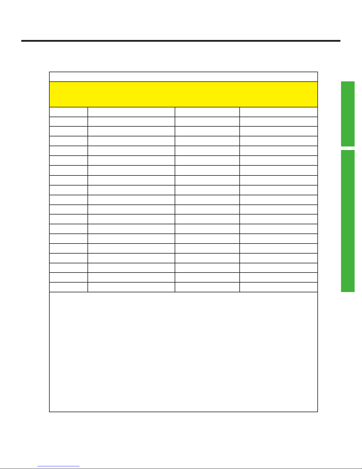
Wiegand Output Format (for prox/Iclass data Format # 1)*
X060 ss sl is il us ul
X061 sb ib ub a b c lpp rpp
X062 1 2 3 oooo ss
ss site start position 00=no site
sl # digits for site 00=remaining
is id start position 00=no id
il # digits for id 00=remaining
us issue code start pos 00=no issue
ul # digits for issue 00=remaining
sb # bits for site code 00=none
ib # bits for id 00=none
ub # bits for issue code 00=none
a site is lsb 0=no 1=yes
b id is lsb 0=no 1=yes
c issue is lsb 0=no 1=yes
lpp left parity bits 000=none
rpp right parity bits 000=none
1,2,3 eld numbers for xmit 1=site,2=id 3=issue,0=none
oooo site override 4 hex characters
ss special format # must be 00
PROGRAMMING
PROX/ICLASS -> WIEGAND OUT
The site code data in the wiegand output is taken from the data characters
starting at position ss for a length of sl. Id and issue code data is also extracted
the same way. If any of the elds are not used, or will be defaulted to 0, then
00 is used for the start position. A length of 00 for sl,il,ul is used to take all of
the remaining characters in the data and put them into the eld. sb,ib, ub are
the bit counts to be used for each eld in the output. If any of the elds are to
be lsb, a,b,c are set to a 1. lpp is the number of bits to use for left parity, 000 if
no left parity. rpp is the number of bits to use for right parity, 000 if none. oooo
is a 4-character hexadecimal value used as a site overide (right justied). To be
active, the site override must be turned on usng the X069 command. ss should
be left at 00.
* added to rmware 5/22/13
Page 45
Page 46

Qscan User’s Guide Version 1.4
Wiegand Output Format (for prox/Iclass data Format # 2)*
X063 ss sl is il us ul
X064 sb ib ub a b c lpp rpp
X065 1 2 3 oooo ss
All parameters are the same as the prior command.
* added to rmware 5/22/13
Wiegand Output Format (for prox/Iclass data Format # 3)*
X066 ss sl is il us ul
X067 sb ib ub a b c lpp rpp
X068 1 2 3 oooo ss
All parameters are the same as the prior command.
* added to rmware 5/22/13
PROGRAMMING
PROX/ICLASS -> WIEGAND OUT
Wiegand Output Site Override Control (for prox/iClass formats)*
X069 a b c
a site override, format 1 0=off 1=on
b site override, format 2 0=off 1=on
c site override, format 3 0=off 1=0n
If any site overrides are specied for any of the three formats, they must
be activated using this command, otherwise the overrides are not used.
* added to rmware 5/22/13
Page 46
Page 47
Qscan User’s Guide Version 1.4
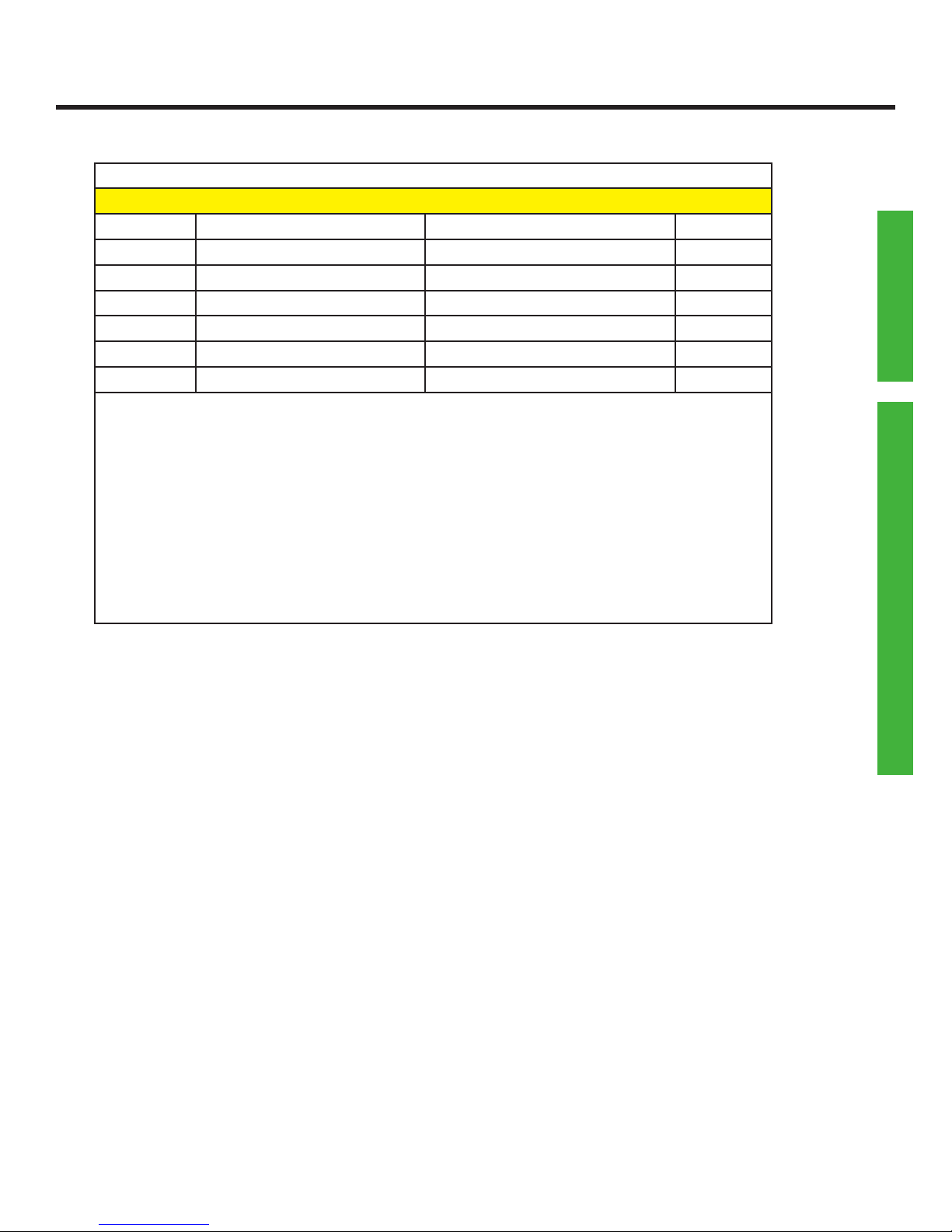
Wiegand Special Output Options*
X070 aa bb cc dd ee
aa special, prox format 1 00= no special format
bb special, prox format 2 01= corporate 1000
cc special, prox format 3 02= Andover 37 bit
dd special, barcode fmt 1
ee special, barcode fmt 2
PROGRAMMING
For any of the three prox/iclass formats, o2 the 2 barcode formats, you
can specify one of the predened special formats. Specify 00 for any
format which will not utilize one of the special formats.
To use the corporate 1000 format, you must also set the site bits to 12,
id bits to 20, with parities turned off. The eld order should be 1,2,0.
To use the Andover 37 bit format, set the site bits to 12, id bits to 19,
issue bits to 4, with no parities. Set the eld order to 3,1,2.
* added to rmware 6/13/13
PROX/ICLASS -> WIEGAND OUT
Page 47
Page 48

Qscan User’s Guide Version 1.4
Programming the Wiegand Output Formats (prox/iClass cards)
The standard wiegand output permits the transmission of wiegand formats of
up to 194 bits, containing up to three elds (site, id, and issue). Each eld can
contain up to 64 bits each. Two parity bits may also be programmed.
Different wiegand output formats can be dened. The format that is used
is dependent on the data which is read by the reader. There are 3 denable
formats for proximity/Iclass data.
For proximity and iClass cards, the format that is used is dependent on the
number of bits on the card (each of the three input format denitions have
their own output denition as well).
Each format contains the denitions of how the data is to be transmitted.
These denitions include:
The number of bits to be used for the site, id, and issue elds
(“ss,bb,ii”)
A setting to organize each eld as msb or lsb (“x,y,z”)
The location(s) in the barcode where the data for each eld is to be
extracted (“ssss,bbbb,iiii”)
PROGRAMMING
PROX/ICLASS -> WIEGAND OUT
The number of characters to use for each of of those elds (“sd,bd,id”)
Which elds are to be included in the output format (“h,i,j”)
Number of bits to be used for left and right parity (“lpp,rpp”)
A site override (“oooo”).
Example programming Prox input Format # 1 for a standard 26 bit input to an
8 digit number (3 site, 5 issue) and then transmitting as
a 32 bit number (16 site + 16 id):
X048 026 002 08 0 010 16 0
X049 000 00 0 03 05 00
X060 01 03 04 05 00 00
X061 16 16 00 0 0 0 000 000
X062 1 2 0 0000 00
Page 48
Page 49

Qscan User’s Guide Version 1.4
Example programming two prox formats. The rst format is a 26 bit input which will
be transmitted as a 26 bit output. The second format will be a 34 bit input ( 1 parity,
16 site, 16 id, 1 parity) retransmitted as a 26 bit output. The passthru option
cannot be used in this case because the passthru option applies to all bit formats.
The transformation from 34 to 26 bits is ok in this case because all of the known
cards in the eld utilize site codes below 255.
X048 026 002 08 0 010 16 0
X049 000 00 0 03 05 00
X060 01 03 04 05 00 00
X061 08 16 00 0 0 0 012 012
X062 1 2 0 0000 00
X050 034 002 16 0 018 16 0
X051 000 00 0 03 05 00
X063 01 03 04 05 00 00
X064 08 16 00 0 0 0 012 012
X065 1 2 0 0000 00
PROGRAMMING
Command Notes:
If site start position (“ss”) is 00, then no site code is extracted from the intermediate
data. You may still include bits in the output format for the site code, except the site
code data will be 0, unless you have programmed a site override.
If site code digits (“sd”) is set to 00, then all remaining digits in the intermediate
data are used for the site code.
If id start position (“is”) is 00, then no id is extracted from the intermediate data.
You may still include bits in the output format for the id, except the id will default to
0.
If id digits (“il”) is set to 00, then all remaining digits in the intermediate data are
used for the id.
If issue code start position (“us”) is 00, then no issue code is extracted from the
intermediate data. You may still include bits in the output format for the issue code,
except the issue code data will default to 0.
If issue code digits (“ul”) is set to 00, then all remaining digits in the intrmediate
data are used for the issue code.
If site code bits (“sb”) is set to 00, then there will be no site bits in the output.
If id bits (“ib”) is set to 00, then there will be no id bits in the output.
Page 49
Page 50

Qscan User’s Guide Version 1.4
If issue code bits (“ub”) is set to 00, then there will be no issue bits in the
output.
If the lsb indicator (“a,b,c”) is on for any specic eld, then the output data
for that eld is set up using the least signicant bit rst. The default for most
wiegand formats is to use msb (most signicant bit rst).
The number of parity bits used for left parity is set by (“lpp”). If set to 000
then there is no left parity bit.
PROGRAMMING
The number of parity bits used for right parity is set by (“rpp”). If set to 000
then there is no right parity bit.
The wiegand output bit structure can consist of 3 elds, plus parities. The
(“1,2,3”) parameters allow you to chose the elds to include and the order of
the elds.
Example: 1,2,0 = transmit site and id
2,0,0 = transmit id only
1,2,3 = transmit site, id, and issue in that order
2,1,0 = transmit id, then site
A site override (“oooo”) can be programmed. This is a 4 character hexadecimal
value (maximum of 16 bits, right justied) which will be used as an override
for the site code if the override X069 is turned on.
(“ss”) refers to a special format number which may be assigned by ibc in
future rmware upgrades. Leave this parameter as 00 unless you have special
rmware assigned by IBC.
WIEGAND OUT
Page 50
Page 51

Qscan User’s Guide Version 1.4
Digital Inputs for Led or Arming Loop use
X029 i p a b
i input 1 0=off 1=bicolor led 2=right led 3=arm loop
p input 1 polarity 0=normal 1=reverse
a input 2 0=off 1=bicolor led 2=right led 3=arm loop
b iinput 2 polarity 0=normal 1=reverse
The digital inputs can be used to control either of the leds, or used for an arming
loop.
Normal polarity is active low.
PROGRAMMING
MISCELLANEOUS
Serial Settings (rs232 only)
X028 b p tt1 tt2
b baud rate 1 thru 8 see table below
p parity 1 thru 3 see table below
tt1 terminator 1 000 thru 255
tt2 terminator 2 000 thru 255
Baud Rate settings can be:
1-1200
2-2400
3-4800
4-9600
5-19200
6-38400
7-57600
8-115200
Parity can be 1=8 bits no parity, 2=7 even, 3=7 odd.
The terminator character(s) can be any decimal ascii character, i.e. 065=“A”. 000
means no terminator.
Page 51
Page 52

Qscan User’s Guide Version 1.4
Special Processing Mode
X030 xx
xx special mode 00=off 01=HID 5352 37 bit emu-
lation (rs232)
The digital inputs can be used to control either of the leds, or used for an
arming loop.
PROGRAMMING
Normal polarity is active low.
Bicolor Led Mode
X031 x
x led style 0=red / green
1=off / red
2=off / green
Controls the color modes of the bicolor led.
Control Card Programming Lockout
X039 x
MISCELLANEOUS
x lockout 0=unlocked
If set to 1 (locked), IBC control cards cannot be used to reprogram the
reader.
1=locked
Page 52
Page 53

Qscan User’s Guide Version 1.4
Aiming Pattern Control
X071 x
x aiming pattern 0=on
1=off
The laser “crosshair” aiming pattern can be turned on or off. By default,
the pattern is on. Shutting off the aiming pattern does not reduce readability.
PROGRAMMING
MISCELLANEOUS
Page 53
Page 54

Qscan User’s Guide Version 1.4
Serial Commands (online mode)
Version Command
V
Returns the rmware identication.
Speaker Command
& xx
Turns the speaker on for xx * 10ms
Led Commands
} xx
Turns the bicolor led on for xx seconds, then leaves it off
{ xx
Turns the bicolor led off for xx seconds, then leaves it on
) xx
Blinks the bicolor led for xx seconds, then leaves it on
( xx
Blinks the bicolor led for xx seconds, then leaves it off
] xx
Turns the green led on for xx seconds, then leaves it off
[ xx
Turns the green led off for xx seconds, then leaves it off
> xx
Blinks the green led for xx seconds, then leaves it on
< xx
Blinks the green led for xx seconds, then leaves it off
ONLINE COMMANDS
Relay Commands
! xx
Turns the relay on for xx seconds
*
Turns the relay off
Page 54
Page 55
Qscan User’s Guide Version 1.4
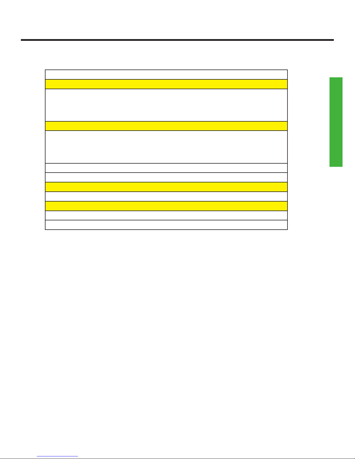
Display Commands
D xxxxxxxxxxxxxxxxxxxxxxxxxxxxxxxx
Displays up to 32 characters on the display (2 lines of 16 characters
each). Note the display is not cleared prior to displaying data, so any
character position not overwritten will remain as it was. You can send any
number of characters, up to 32.
d xxxxxxxxxxxxxxxx
Displays up to 16 characters on line 2 of the display. Note the display is
not cleared prior to displaying data, so any character position not over-
written will remain as it was. You can send any number of characters, up
to 16.
Digital Input Commands
%
Returns the status of Input 1 ( ON or OFF )
$
Returns the status of Input 2 ( ON or OFF )
ONLINE COMMANDS
Page 55
Page 56

Qscan User’s Guide Version 1.4
Updating Firmware and Serial Emulation
You can update Qscan readers using the ibc Flash Utility found on our website at
http://interbar.com.
Rs232 and Tcp/ip readers can be updated directly through their serial connections.
To update Qscan readers with emulations interfaces you will need to make a cable to
connect the reader to a pc or laptop. The wiring connections are:
Red Power
Blue Ground and DB9 pin 5
Green DB9 pin 2
Yellow DB9 pin 3
Connect Orange and White together
Connect DB9 pins 7 and 8 together
SERIAL EMULATION AND FIRMWARE UPDATES
You must connect orange and white together before applying power. This is the
signal to the Qscan reader that you want to start up in a serial mode so that you can
download the new rmware. The reader will start up at 9600 baud, 8 data bits, no
parity.
Besides updating rmware, Qscan readers with an emulations interface can be started
up in the serial mode for the following purposes:
Sending programming commands to the reader
Viewing barcode data through the serial connection.
In case you are having issues with wiegand programming not working and you need
to view what is encoded in a barcode, you can do this with a seial connection using
the wiring pinout described above. Use the terminal mode from any of the ibc utility
software programs to view the data.
Page 56
Page 57

Qscan User’s Guide Version 1.4
Wiegand Bit Size Table
This table shows the number of bits required to encode a specic number into
wiegand. This table can also be used to see how many charcters are required to
decimalize wiegand input elds.
Bits Decimal Number
1 1
2 3
3 7
4 15
5 31
6 63
7 127
8 255
9 511
10 1 023
11 2 047
12 4 095
13 8 191
14 16 383
15 32 767
16 65 535
17 131 071
18 262 143
19 524 287
20 1 048 575
Bits Decimal Number
33 8 589 934 591
34 17 179 869 183
35 34 359 738 367
36 68 719 476 735
37 137 438 953 471
38 274 877 906 943
39 549 755 813 887
40 1 099 511 627 775
41 2 199 023 255 551
42 4 398 046 511 103
43 8 796 093 022 207
44 17 592 186 044 415
45 35 184 372 088 831
46 70 368 744 177 663
47 140 737 488 355 327
48 281 474 976 710 655
49 562 949 953 421 311
50 1 125 899 906 842 623
51 2 251 799 813 685 247
52 4 503 599 627 370 495
BIT SIZE TABLE
21 2 097 151
22 4 194 303
23 8 388 607
24 16 777 215
25 33 554 431
26 67 108 863
27 134 217 727
28 268 435 455
29 536 870 911
30 1 073 741 823
31 2 147 484 647
32 4 294 967 295
53 9 007 199 254 740 991
54 18 014 398 509 481 983
55 36 028 797 018 963 967
56 72 057 594 037 927 935
57 144 115 188 075 855 871
58 288 230 376 151 711 743
59 576 460 752 303 423 487
60 1 152 921 504 606 846 975
61 2 305 843 009 213 693 951
62 4 611 686 018 427 387 903
63 9 223 372 036 854 775 807
64 18 446 744 073 709 551 615
Page 57
Page 58

USER NOTES
Qscan User’s Guide Version 1.4
Page 58
Page 59

USER NOTES
Qscan User’s Guide Version 1.4
Page 59
Page 60

Qscan User’s Guide Version 1.4
International Bar Code
160 Oak Street
Glastonbury, CT 06033
phone 860 659 9660
fax 860 657 3860
Page 60
 Loading...