

intermovtive PRPC501-A User Manual
An ISO 9001:2008 Registered Company
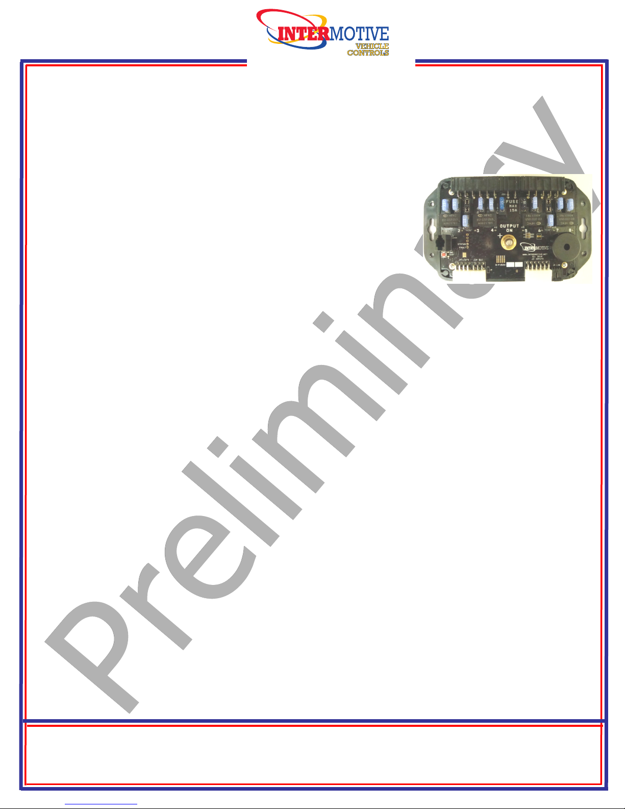
PRPC501-A
Programmable Relay Power Center
See PRPC Programming Utility software for latest list of supported vehicles
2009-2014 Ford E-Series and F-Series
Contact Intermotive for additional applications
Introduction
The Programmable Relay Power Center provides access to a broad
range of vehicle data such as MPH, RPM, Park Brake, Service Brake,
temperatures, transmission range, accelerator pedal, doors, lights,
door locks, ABS, MIL, etc. Specific data is vehicle dependent, and by
running the PRPC Programming Utility software (free download from
www.intermotive.net), available information on a particular chassis can easily be determined.
The PRPC provides 8 configurable relay outputs, eight configurable low current outputs
(1/2A Max), and six configurable beepers. The Programmer allows logical combinations
(AND, OR, =, >, <) of various vehicle data to control an output. For example, one output can be
programmed to go active when ECT>230 OR TFT>250 AND RPM>300 (any numeric values can
be used). This could drive a high temperature dash indicator. Another output could be
programmed to drive a warning buzzer/lamp when the vehicle speed exceeds some limit, such as
70mph. Electric doors can be disabled unless certain safety conditions are met and so on. There
are also ten general purpose inputs, one analog input, and one dedicated ignition input that can
be used as part of the programmable logic.
PRPC Programming Ulity Instrucons
(Used for configuring the programmable outputs, beepers and inputs)
Requirements:
• Java Runtime Environment (v1.7.0 or later) must be installed on your computer prior to running
this utility. Most PC’s already have Java installed. The most recent version can be obtained for
free at http://java.com/en/download/manual.jsp.
• The PRPC Programming Utility. This is a free Intermotive software program that will need to
be loaded on your PC. The files are available from the download page at
www.intermotive.net. It is recommended that an “InterMotive” folder be created to store the
files.
• USB to Serial cable (part# s-h37a1) is included in the a-IPU kit and is a one-time purchase.
This kit is required for all programming and is recommended to be kept in a central location.
Once PRPC Programming Utility has been run and the specific configuration has been created, it
can be downloaded onto the PRPC501-A module(s) with the Programming Utility.
InterMotive Inc.
13395 New Airport Rd.
Auburn, CA 95602
Phone: (530)-823-1048
Fax: (530)-823-1516
Page 1 of 13
www.intermotive.net
products@intermotive.net
PRPC501-A-090314-INS
Computer Installation:
1. Ensure the proper driver is installed for the USB to Serial download cable. This driver
can be found at: http://www.ftdichip.com/Drivers/VCP.htm
2. To install the programming utility, unzip the PRPC Programming Utility folder to your
local hard drive.
3. Create a shortcut on the desktop if necessary, but do not
separate the PRPC Programming Utility.exe file from the
rxtxSerial.dll file!
4. Plug in the USB cable (Part# s-h37a1) prior to starting the
application.
5. Double click the PRPC Programming Utility.exe file to launch.
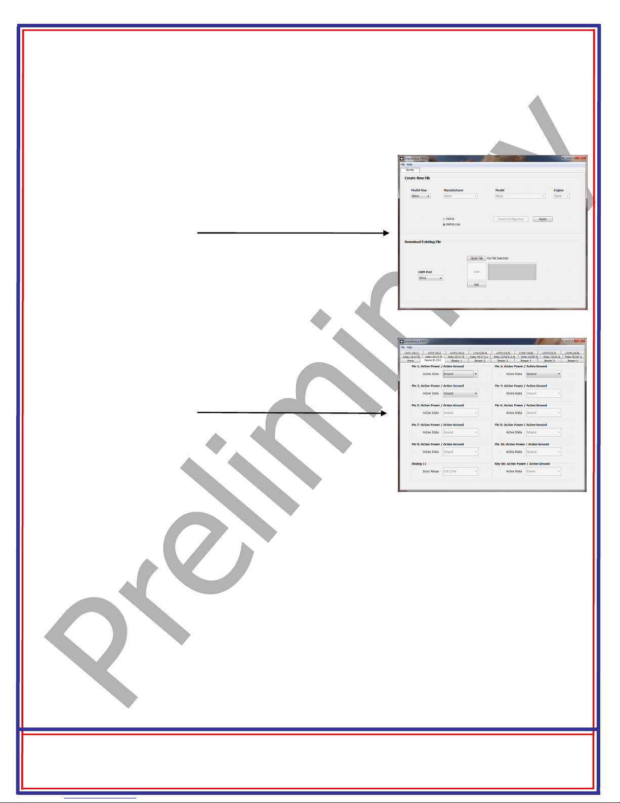
6. This screen will come up.
If the program does not launch, close all applications and reinstall
the Java Runtime Environment and the PRPC Programming Utility.
Setting the PRPC Programming Utility Pin Configurations:
To view a video on tips for configuring the module, go to www.Intermotive.net
1. Under the “Home” tab select the model year, manufacturer,
model, and engine size of the vehicle the PRPC will be installed in.
2. Click the “Create Configuration” button.
3. This screen will come up.
4. Configure as desired. See the following page for more information. Press the Enter button after each entry.
Note: CTO can only be programmed on LCO5 (J4-5).
2.2 Hz per MPH can only be programmed on LCO6
(J4-6).
5. Select “Save Configuration” under the “File” tab.
6. Enter a configuration name (Max. 16 characters) and click “OK”.
7. Review the configuration summary and click “Save Configuration”.
8. Enter a filename and choose a location that will be easy to locate.
9. Under the “File” menu, select “Save Configuration Summary”.
10. Double click the .ims file previously configured.
11. Enter Company Name, phone number, and notes and click the ‘OK’ button. Note: Enter
the vehicle model year, model, and engine in the notes section.
12. Enter a file name and click the ‘Save’ button.
13. Click the ‘Open File’ button.
14. Right click on summary and select ‘Print’.
15. Cut the printed label and place it in the bag attached to the PRPC module.
InterMotive Inc.
13395 New Airport Rd.
Auburn, CA 95602
Phone: (530)-823-1048
Fax: (530)-823-1516
Page 2 of 13
www.intermotive.net
products@intermotive.net
PRPC501-A-090314-INS
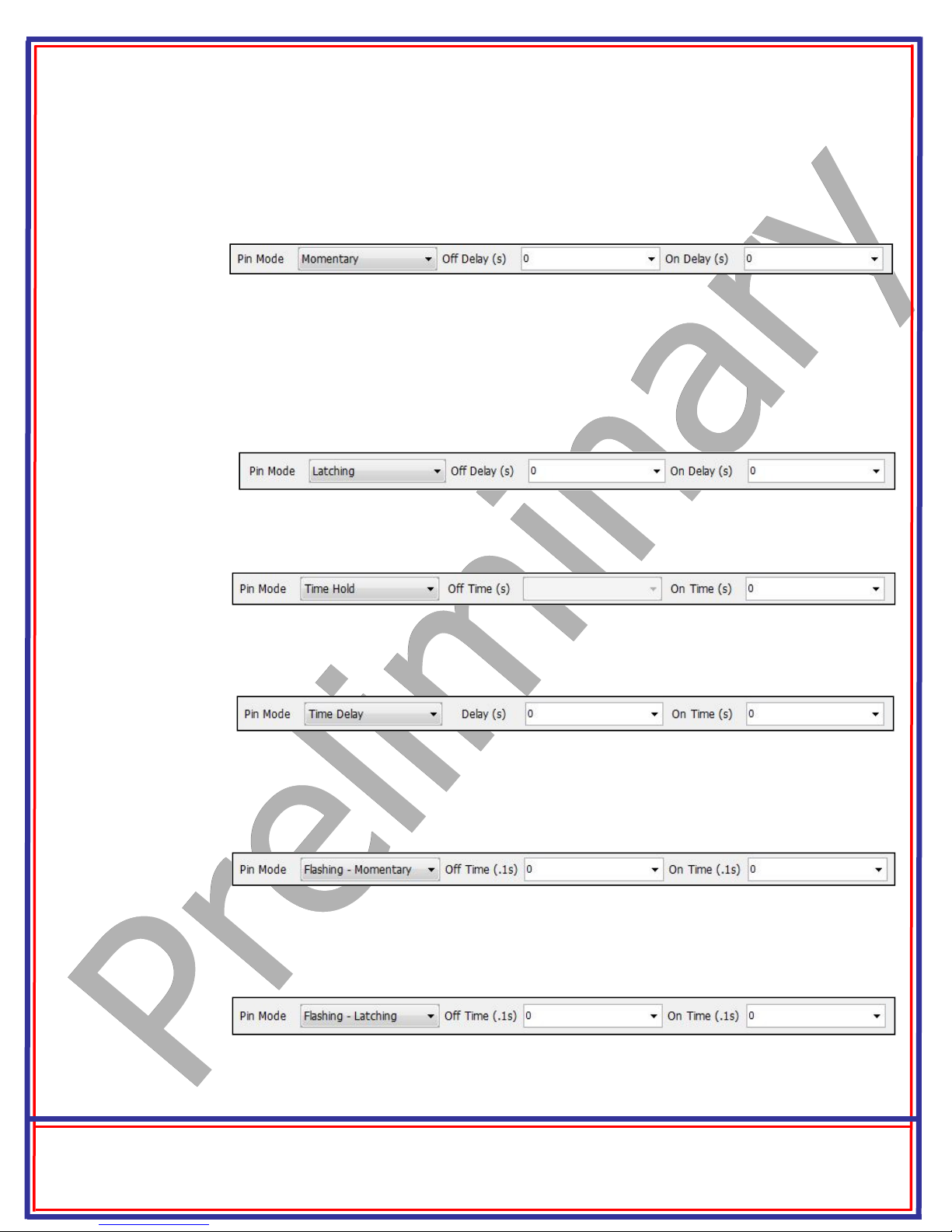
Setting Pin Mode— PRPC Application Software
Momentary: Output follows condition set but with a turn on delay, and a turn off delay. Setting ‘On
Delay’ and ‘Off Delay’ to zero causes the output pin to simply “follow” the condition set being true (ON)
and false (OFF).
Latching: This mode will latch an output pin ON, starting ‘On Delay’ seconds after the conditions are
met, and will keep it ON even after the conditions are no longer true. It will then latch the output OFF,
following ‘Off Delay’ seconds after the conditions are met again. It can be thought of as toggle
On/toggle Off. The simplest use would be when using a momentary button as the only input condition
and setting the Delays to zero. Thus a load could be turned on by pushing a momentary button, and
turned back off by pushing the button a second time.
Time Hold: The output pin goes ON after the conditions become true, and stays ON for the selected
‘On Time’, regardless of the conditions. Off Time is Not Applicable.
Time Delay: Output is turned ON after the selected ‘delay’ time after the conditions are met. It
stays on for selected ‘On time’, regardless of input conditions.
Flashing—Momentary: Used for creating a flashing output. When conditions are met, output flashes. When conditions are no longer met, flashing stops. Flashing ON and OFF times (duty cycle) are
controlled by entering the following values.
Flashing - Latching: Same as above, except flashing will continue after conditions are no longer
true, and will stop when conditions become true again—toggle ON, toggle OFF. Duty cycle is controlled by the ON and OFF times.
InterMotive Inc.
13395 New Airport Rd.
Auburn, CA 95602
Phone: (530)-823-1048
Fax: (530)-823-1516
Page 3 of 13
www.intermotive.net
products@intermotive.net
PRPC501-A-090314-INS

Desktop Programming the PRPC
The InterMotive “a-IPU” kit is sold separately and allows programming the PRPC on your desktop. It consists of a 12VDC wall
adapter and download cable and works with the PRPC programming software utility.
Note: Do not have the PRPC Programming Utility opened
until instructed to do so.
1. Plug the Module Desktop Power/Ground Supply inverter
into a 120V AC power source.
2. Locate the 6-Pin Female connector on the module but
do not connect the AC adapter to the PRPC module
until indicated in the following steps.
3. Plug the phone jack end of the download cable into the
J8 COMM port of the PRPC module and the USB end into
your PC.
J8 COMM Port
Loading your previously created Configuration file into the PRPC:
Open the PRPC Programming Utility. Under the “Home” tab on the PRPC Programming Utility,
choose the COM Port the USB cable is connected to.
Note: This can be determined on Windows XP by right-clicking on ‘My Computer’ and selecting
‘Properties.’ From this window select the ‘Hardware’ tab and click on ‘Device Manager.’ In the Device Manager window, expand the ‘Ports’ menu and the download cable will display as ‘USB Serial
Port.’
Click the ‘Open File’ button.
1. Open the PRPC*.ims or configuration file to load on the PRPC501-A module. (This file
must already be loaded on the computer).
2. Click the load button on the computer screen. “Waiting” will come up next to the progress bar.
This means the program is waiting for the power to be plugged into the PRPC module.
3. Plug in the 6 pin connector of the power adapter into the PRPC501-A module. The progress bar
on the computer screen will display status as the configuration loads and takes approximately 2
seconds or less. Configuration is loaded once the screen says “DONE” and programming is
complete.
4. To verify that the correct data was loaded into the module, disconnect the 6 pin connector
from the module and press the ‘Get” button on the screen. Plug in the 6 pin connector and
the information will be displayed.
To program another module with the same configuration file, start with step 2.
InterMotive Inc.
13395 New Airport Rd.
Auburn, CA 95602
Phone: (530)-823-1048
Fax: (530)-823-1516
Page 4 of 13
www.intermotive.net
products@intermotive.net
PRPC501-A-090314-INS
 Loading...