

Page 1
Metro®
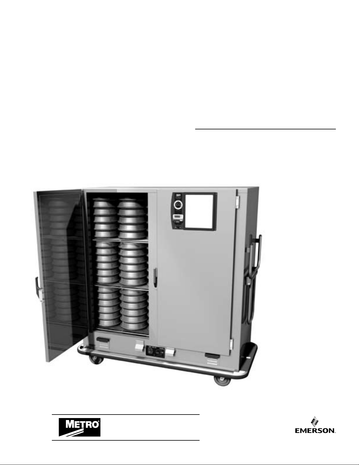
Heated
Banquet
Cabinets
USER MANUAL
This manual covers cabinets with electrical ratings
of: 120V 1650W & 220V 1650W.
When ordering
electrical parts, always
confirm the rating
listed on data plate
located on the lower
left side of the unit.
Differences on voltage,
amps or wattage are
listed with bold text
in replacement part
descriptions.
InterMetro Industries Corporation
Wilkes-Barre, PA 18705
570-825-2741
Metro Heated Cabinets are for
Food Service applications only.
Page 2

Table of ConTenTs
SECTION PAGE
I. Introduction
A. Identifying Your Cabinet ..................................2
B. Features ...........................................................3
II. Operating Instructions
A. Electric Heating System ..................................3
B. Canned Fuel System .......................................3
C. Count-up/Count-down Timer/Clock ................4
III. Cleaning Instructions
A. Shelf Removal/Installation .............................. 4
B. Electric Heating Module
Removal/Installation ........................................4
C. Quad-Heat Dual Fuel
Removal/Installation ........................................5
D. Specific Cleaning Instructions ........................5
E. General Cleaning Instructions ........................5
IV. Maintenance
A. Cabinet Maintenance ......................................5
B. Electric Heating Module ..................................5
C. Blower Motor Maintenance .............................5
V. Replacement Parts and Procedures
A. Cabinet ............................................................6
B. Electric Heating Module ..................................8
C. Battery Replacement —
Count-up/Count-down Timer/Clock ................8
D. Swivel-Lock Operation ....................................9
E. Swivel-Lock Caster System ...........................11
F. Quad-Heat System ........................................12
VI. Wiring Schematic ..............................................13
Warranty .............................................................14
1
Page 3
I. InTRoDUCTIon
A. IDENTIFYING YOUR CABINET
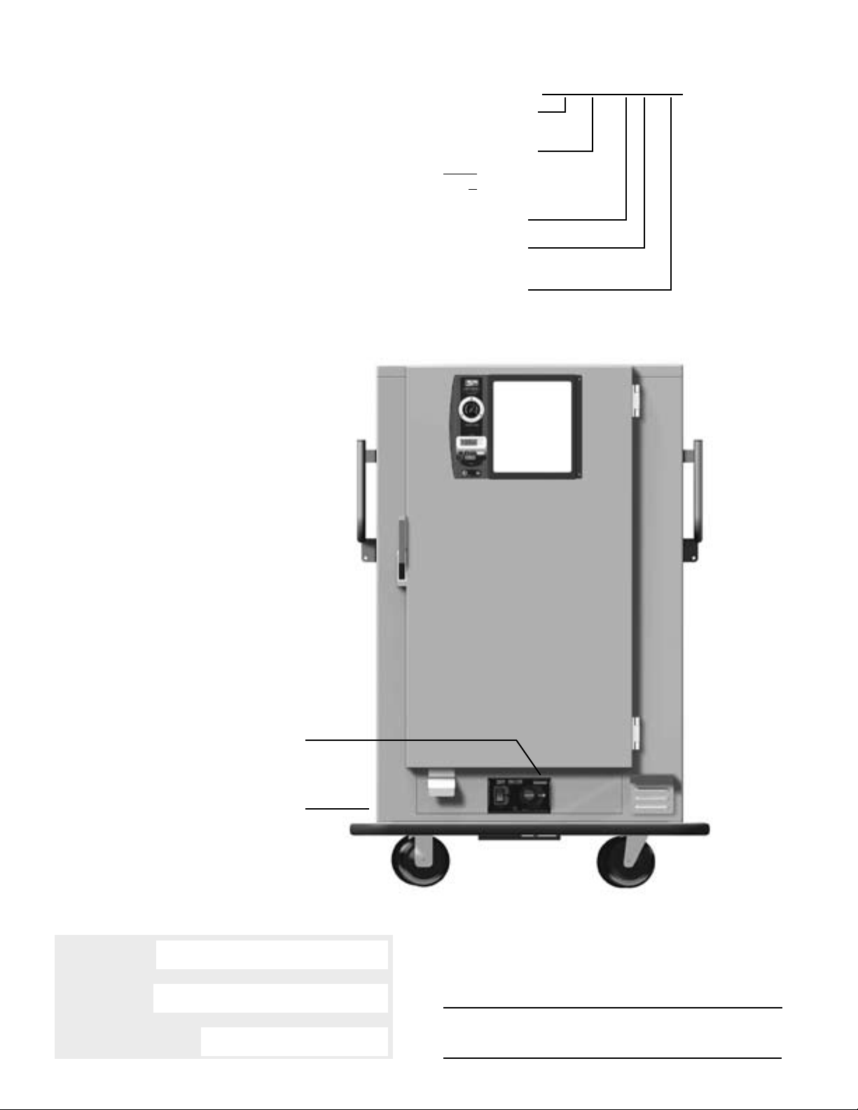
There are two numbers, which you may want
to record for future reference: the cabinet
model number, serial number, and the module
serial number. Refer to the photo below to
locate these numbers. It is recommended that
all numbers be recorded in an appropriate
place, such as on this page (see below). Also,
please record the cabinet model number and
module serial number on the Warranty Card
found at the back of this manual. Be sure to
complete the remainder of the Warranty Card
and return it to Metro within fifteen (15) days
of delivery of the cabinet. Once you have
located and recorded these numbers, refer
to the sample numbers given to the right to
identify the components of your cabinet.
sample of CabIneT labelIng
mbQX-200D-QH
Cabinet Series
Cabinet Elect.
Rating Type
blank = 120V, 1650W
X = 220V, 60HZ, 1650W
Cabinet Size
Double Door
(Blank for Single Door)
Quad-Heat
(Dual Fuel)
LOCATION
OF MODULE
SERIAL NUMBER
LOCATION OF CABINET MODEL
NUMBER AND SERIAL NUMBER
(Silver Label on Side of Cabinet)
▼
Model Number ________________________________
Serial Number ________________________________
Module Serial Number __________________________
▼
NOTE: Please read this manual thoroughly before using your
cabinet. If you should have questions, please contact
Metro customer service department.
2
Page 4

B. FEATURES — ALL MODELS
In order to utilize your new cabinet to its full potential;
take a minute to identify the following features that have
been provided for your convenience.
• The module has been placed at the base of the
cabinet for easy accessibility and efficient operation.
• Clearly marked control panel for easy viewing and
allowing temperature adjustments without opening
the door.
• Handles on each end of the cabinet.
• Optional swing-up handle.
• Thermometer, timer and dual function white board/
clipboard on the door.
• Easy pull magnetic door latch.
• Kick latch on all doors.
• All components — door, module and shelves are
removable to permit thorough, obstruction-free
cleaning.
• Optional swivel-lock caster system.
• Optional canned fuel system. Includes chimney,
baffles and canned fuel drawers. All are removable
to permit thorough, obstruction-free cleaning.
• Optional travel latch.
II. OPERATING INSTRUCTIONS
A. ELECTRIC HEATING SYSTEM
Your cabinet is designed to MAINTAIN the
temperature of HOT prepared foods. The
module is equipped with a thermostatically
controlled heater and a blower for air
circulation. A POWER switch is provided along
with a red light to indicate when the unit is
switched ON. Next to the POWER switch is the
TEMPERATURE control.
A short, grounded, module power supply cord is
supplied fixed to the module. This power supply
cord must be unplugged from the cabinet power
supply cord as the module is removed from the
cabinet. The cabinet power supply cord is fixed
to the underside of the cabinet. Likewise, when
installing the module into a cabinet, the module
power supply cord must be plugged into the
cabinet power supply cord.
1. Refer to the data plate located near the
power cord for the electrical specifications of
cabinet. With the power switch off, plug the
cord into the appropriate rated, grounded
receptable. Cabinets rated at 120V 20
amp must be plugged into a 125VAC 20
amp receptacle and must be used on an
individual branch circuit. Cabinets rated at
120V 15 amp may be plugged into either a
15 amp or 20 amp receptacle.
Cabinets rated at 220V 1650W must be
plugged into a 250VAC 15 amp receptacle.
NOTE: A 15 amp cabinet can be plugged
into 20 amp service. A 20 amp unit must be
plugged into a 20 amp receptacle.
120V 120V 220V
15 AMP PLUG 20 AMP PLUG 15 AMP PLUG
2. Snap POWER switch to ON. The red POWER
light will now glow and the blower will begin
circulating air. Note: This is not a foot switch.
Operating it with your foot can damage the
switch and make the cabinet inoperable.
3. Turn the TEMPERATURE thermostat to a setting
of 10. The holding unit is now in operation.
4. After allowing the cabinet to PREHEAT
FOR APPROXIMATELY 45/60 MINUTES,
reduce the thermostat setting to 6/8. In a
room of average temperature (72°F) this
should provide 150° to 170°F (65°-76°C).
Adjustments to the temperature may be
made as necessary.
THIS IS A HOT FOOD HOLDING
CABINET AND IS NOT INTENDED TO
RETHERMALIZE COLD FOOD. MAKE
SURE FOOD AND CABINETS ARE AT
PROPER TEMPERATURES BEFORE
PLACING FOOD IN THE CABINET.
NOTE: The POWER (red) light will glow
as soon as the POWER switch is switched
ON and will continue to glow until switched
OFF. The blower will operate as long as the
POWER switch is ON.
It is not necessary at the end of the operating
day to disrupt the TEMPERATURE setting in
order to turn the unit OFF. By switching the
POWER switch to OFF, the unit is no longer
operating. By switching the POWER switch to
ON when resuming operations, the cabinet
will attain the preset level (or it can be
preheated at a setting of 10 before adjusting
to the desired temperature).
B. CANNED FUEL SYSTEM (Optional)
The Canned Fuel system does not require
the electric heating module to be turned on
for operation. Each bottom-mounted drawer
holds 2 cans of fuel. Lift slightly and pull the
drawer out until it stops or lift the drawer front
and remove it from the cabinet. Place a fuel
can into each round cutout and light the fuel.
Close the drawer.
NOTE: Filling each canned fuel drawer with
2 cans of fuel will heat the unit to 200°F in
approximately 45 minutes. In order to maintain
a desired temperature, some of the canned
fuel cans may need to be extinguished.
Follow manufacturer’s guidelines for canned
fuel usage.
3
Page 5

C. COUNT-UP/COUNT-DOWN TIMER/CLOCK
CLOCK MODE
1. Press the Mode button until the clock icon
appears on screen next to the printed
“CLOCK” icon.
2. Press and hold (SET) for two seconds.
3. “HOURS” will flash.
4. Press ( ▲ ) or ( ▼ ) to set.
5. Repeat process to set minutes or seconds.
6. To complete the process press (SET).
NOTE: The two-second delay is to prevent
accidental changing of time. There is no
delay in Timer mode.
COUNT-DOWN TIMER MODE
Can be used to countdown the minutes until the
canned fuel needs to be replenished.
1. Press the Mode button until the timer icon
appears on the screen next to the printed
“TIMER” icon.
2. Press (SET).
3. “HOURS” will flash.
4. Press (▲) or (▼) to set up or down to desired
interval (23:59:59 max.).
5. Repeat process to set minutes or seconds.
6. Press (START) to start. Press (STOP) to stop.
HELPFUL HINTS:
• If you want to set only hours, it is not
necessary to press (SET) through minutes
and seconds. Simply set desired interval and
press (START).
• As a reminder, your timer will “beep” for 3
seconds when it reaches 5 minutes before
set interval expires.
• When timer reaches 00:00:00 the alarm will
sound and “TIME’S UP!” will appear on the
screen. Your timer will now begin to count
up. The alarm will stop after 60 seconds and
your timer will continue to count up until you
press (STOP).
• (CLEAR) button can be used at any time
to clear the display. (CLEAR) button also
functions for recall of last setting.
• (RECALL) feature: after you press (STOP),
pressing the (RECALL) button will
automatically display the last timer setting.
• Each time you press ( ▲ ) or ( ▼ ) the
digits will change once. If you hold the button
down digits will change rapidly.
COUNT-UP TIMER MODE
Can be used to track how long food has been in
the cabinet.
1. Press the Mode button until the stop watch
icon appears on screen next to the printed
“STOP WATCH” icon.
2. Press (START) to start. Press (STOP) to stop.
III. CleanIng InsTRUCTIons
CAUTION
AT NO TIME SHOULD THE MODULE OR
CABINET BE WASHED OR FLOODED WITH
WATER OR LIQUID SOLUTION. NEVER
STEAM CLEAN. SEVERE DAMAGE OR
ELECTRICAL HAZARD COULD RESULT.
1. Turn off power switch.
2. Unplug the unit from its power source.
WARNING
ALLOW THE UNIT TO COOL BEFORE
CLEANING, AS THE INTERIOR OF THE
CABINET MAY BE HOT ENOUGH TO BURN.
A. SHELF REMOVAL/INSTALLATION
To remove the shelves, all shelves must first
be lowered onto the bottom shelf. Start with
the shelf above the bottom shelf by lifting it off
of the shelf hangers and by lowering the front
edge and raising the rear edge so that it can
be lowered onto the bottom shelf. Repeat the
procedure until all of the shelves are on the
stack on the bottom shelf.
On double door cabinets, lift the uppermost
shelf off of the stack so that you are holding
onto the long edge of the shelf and the shelf
is hanging vertically. Position the shelf so one
vertical edge is in one of the rear cabinet
corners. Swing the other vertical edge out the
door and remove the shelf. Repeat until all the
shelves are removed.
On single door cabinets, lift each shelf off of
the stack so that you are holding onto the long
edge of the shelf and the shelf is hanging
vertically. Position the shelf so that one vertical
edge is in one of the rear cabinet corners and
the other vertical edge is towards the diagonal
front corner. Depending on the model of the
one door cabinet, the shelf may have to be
rotated towards a vertical position to remove it
from the cabinet.
To install the shelves, reverse the above
procedure. Before installing the shelves
install the module (Section B below) and, if so
equipped, the Quad-Heat Fuel System baffle(s)
and chimney(s) (Section C below).
NOTE: The shelf wires that run from left to right
in the cabinet should be on the top side of the
installed shelves. Make sure the shelves are
seated in the hangers correctly.
On single door MBQ-90 and 72 cabinets, the
shelves have two 90° square corners and two
45° notched corners. The 45° corners go to the
right end as you look into the cabinet.
B. ELECTRIC HEATING MODULE
REMOVAL /INSTALLATION
1. Remove the module from the cabinet by
lifting and sliding the module rearward. Lift
the front of the module and stand it vertically
4
Page 6

on the floor of the cabinet. The control panel
will be facing the ceiling. Unplug the module
power supply cord from the cabinet supply
cord and remove the module from the cabinet.
2. Do not use abrasive cleaners. For every
cleaning method, best results are always
obtained when the cleaner and technique
are matched to the soil conditions involved.
Contact your detergent representative to
ensure the cleaning product being used is
recommended for use on stainless steel.
Follow the manufacturer’s directions on
cleaners. Never mix cleaners.
CAUTION
DO NOT ALLOW THE CABINET POWER
SUPPLY CORD RECEPTACLE TO COME IN
CONTACT WITH WATER OR CLEANSERS.
IT MUST BE DRY BEFORE PLUGGING THE
MODULE POWER SUPPLY CORD INTO IT.
C. QUAD-HEAT DUAL FUEL SYSTEM
REMOVAL /INSTALLATION
1. The heat conductive baffles spread the heat
from the canned fuel drawers to the corner
chimneys. The heat baffles are next to the
standard electric module. First, remove the
Electric Heating System module. To remove
a baffle, lift up on the recessed handle to
disengage the edge of the baffle from the
locator pin in the bottom of the cabinet. Then
slide the baffle away from the nearest end of
the cabinet until it clears the shelf hangers
and lift it out of the cabinet.
2. To remove the corner chimneys (after
removing the heat conduction baffles) put
your thumb and finger into the two holes near
the upper end of the chimney and lift the
chimney off its hanger and remove it from
the cabinet.
To install the Quad-Heat dual fuel system,
reverse the above instructions. When
installing the chimneys, make sure they
are securely seated on the hangers. When
sliding the baffles to the end of the cabinet,
make sure the slots in the bottom of the
chimney engage the baffle and that the
baffle is locked into the locator pins by
pushing down on the recessed handle.
D. SPECIFIC CLEANING INSTRUCTIONS
CAUTION
DO NOT IMMERSE THE ELECTRIC HEATING
MODULE WHEN CLEANING.
1. Use a damp cloth and dry with a towel.
Special attention should be paid to keeping
the air-inlet area and the controls area free of
dirt build-up.
BE SURE TO THOROUGHLY DRY THE
MODULE BEFORE RETURNING IT TO USE.
2. Do not neglect to clean the under-chassis
area, especially the area above each caster.
3. The cabinet or component(s) must be
thoroughly rinsed to remove any residue that
may stain the materials.
E. GENERAL CLEANING INSTRUCTIONS
1. LIGHT SOIL
If routine (daily) cleaning is practiced, a mild
soap and warm water should be sufficient to
keep the unit clean.
2. HEAVIER SOIL
If cleaning has been postponed, solvent or
emulsion type cleaners that can be applied
with bare hands will give excellent results.
Such cleaners are available under various
brand names. Detergent suppliers can
recommend materials appropriate for use on
stainless steel.
NOTE: For every cleaning method, best
results are always obtained when the cleaner
and techniques are matched to the soil
conditions involved. To ensure using the
proper cleaner for stainless steel, contact
your detergent representative.
IV. maInTenanCe
A. CABINET MAINTENANCE
Your cabinet has been designed to require
very little maintenance. With normal use,
cleaning is the only form of maintenance
that needs to be done on a regular basis.
Keeping the casters free of dirt build-up will
go a long way in prolonging their life.
If your cabinet is rolled over rough surfaces
or transported over the road, the various
threaded fasteners, i.e., screws and nuts,
should be periodically inspected and tightened if necessary, particularly the handles,
door hinges and caster fasteners.
B. ELECTRIC HEATING MODULE
MAINTENANCE
The module in the base of your cabinet has
also been designed to require very little
maintenance. With normal use, cleaning is
the only form of maintenance that needs to
be done on a regular basis. When cleaning,
do not spray or pour water on the module
and do not immerse the module in water.
Wipe with a damp cloth and dry with a towel.
Keeping vital areas such as the air-inlet area
and the controls area free of dirt build-up will
go a long way in prolonging the life of the
electrical components. No maintenance is
required on the electrical components.
C. BLOWER MOTOR MAINTENANCE
The blower motor requires no maintenance
other than keeping the unit clear of dirt, dust
and food particles.
5
Page 7
10
7
24
23
21
20
11
5
8
1
2
9
6
4
3
19
18
15
16
17
14
13
12
22
V. ReplaCemenT paRTs anD
ReplaCemenT lIsT
A. CABINET — ALL MODELS
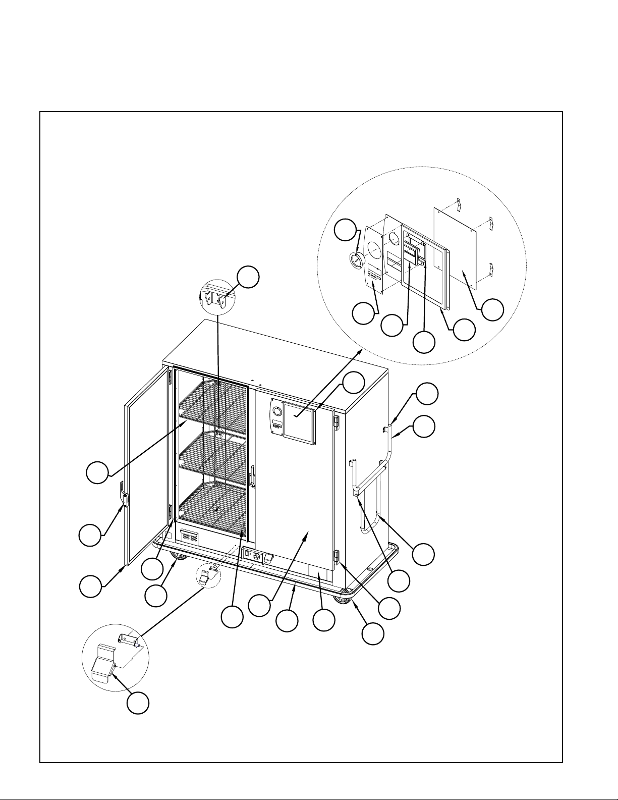
Refer to the Cabinet Replacement Parts List on
page 7 to identify the replacement parts.
Cabinet Replacement Parts Diagram
6
Page 8
7
CABINET REPLACEMENT PARTS LIST
Item No. Part No. Description
1 RPC14-042 HINGE
2 RPSEFS-200RDOR RIGHT DOOR MBQ-200D UNITS ONLY
RPSEFS-180RDOR RIGHT DOOR MBQ-180D, MBQ-180, MBQ-144 UNITS ONLY
RPSEFS-150RDOR RIGHT DOOR MBQ-150D, MBQ-120, MBQ-90 UNITS ONLY
RPSEFS-120RDOR RIGHT DOOR MBQ-120D & MBQ-72 UNITS ONLY
3 RPC14-118A LATCH
4 RPSEFS-200LDOR LEFT DOOR MBQ-200D UNITS ONLY
RPSEFS-180LDOR LEFT DOOR MBQ-180D UNITS ONLY
RPSEFS-150LDOR LEFT DOOR MBQ-150D UNITS ONLY
RPSEFS-120LDOR LEFT DOOR MBQ-120D UNITS ONLY
5 RPC11-446 HANDLE
6 MBQ-DRGSKT-36 DR GASKET X 36.313 HI, MBQ-72,-120D
MBQ-DRGSKT-44 DR GASKET X 44.813 HI, MBQ-90,-120,-150D
MBQ-DRGSKT-54 DR GASKET X 52.813 HI, MBQ-144,-180,-180D
MBQ-DRGSKT-59 DR GASKET X 59.313 HI, MBQ-200D
7 RPSHELF-HANG SHELF SUPPORT KIT (INCLUDES HARDWARE)
8 RP6-SWIVEL 6” SWIVEL CASTER KIT
RP8-SWIVEL 8” SWIVEL CASTER KIT HARDWARE INCLUDED
RP8-AIRSWIVEL 8” SWIVEL AIR CASTER KIT
9 RP6-RIGID 6” RIGID CASTER KIT
RP8-RIGID 8” RIGID CASTER KIT HARDWARE INCLUDED
RP8-AIRRIGID 8” RIGID AIR CASTER KIT
10 RPKICK-LATCH KICK LATCH KIT
11 RPC06-201 BUMPER-SWING HANDLE
12 RPC13-189 THERMOMETER (INCLUDES BULB CLAMP)
13 RPC05-905 OVERLAY-BEZEL
14 RPC13-194 TIMER
15 RP-WHITEBRD WHITE BOARD
16 RP-BEZELPNL BEZEL PANEL
17 RP-TMRBRKT TIMER BRACKET
18 RPC06-035 POST CAP
19 RP-BEZELBUMP BEZEL BUMPER KIT MBQ-180, MBQ-144 & MBQ-120 ONLY
20 RPDD-SHELF SHELF — ALL DOUBLE DOOR CABINETS
RP180-SHELF SHELF — MBQ-180
RP144-SHELF SHELF — MBQ-144 & MBQ-120
RP90-SHELF SHELF — MBQ-90 & MBQ-72
21 RPCF-DDCOV CANNED FUEL OPENING COVER-DOUBLE DOOR CABINETS WITH HARDWARE
RPCF-SDCOV CANNED FUEL OPENING COVER-SINGLE DOOR CABINETS WITH HARDWARE
22 RP15AMP-CORD 120V, 15 AMP POWER CORD
RP20AMP-CORD 120V, 20 AMP POWER CORD
RP220V-CORD 220V, 15 AMP POWER CORD
23 RPF04-004C SWING-UP HANDLE HDWE
24 RPDD-BUMPER CABINET BUMPER ASSEMBLY — DOUBLE DOOR CABINETS
RP180-BUMPER CABINET BUMPER ASSEMBLY — MBQ-180 CABINETS ONLY
RP144-BUMPER CABINET BUMPER ASSEMBLY — MBQ-144 & MBQ-120 CABINETS ONLY
RP90-BUMPER CABINET BUMPER ASSEMBLY — MBQ-90 & MBQ-72 CABINETS ONLY
Page 9

B. ELECTRIC HEATING MODULE
CAUTION
DO NOT ATTEMPT TO SERVICE THE
MODULE UNLESS YOU ARE QUALIFIED
AND KNOWLEDGEABLE OF ELECTRICAL
REPAIRS AND ELECTRICAL SAFETY.
Your module has been designed to be user-
serviceable, assuming a basic knowledge
of the operation of electrical devices. This
section has been written to guide the user step
by step, and in layman’s terms, through the
dismantling and servicing of the module. Before
attempting to service your module, read the
appropriate Module Repair Procedures (found
elsewhere in this section) thoroughly. If you do
not understand the Repair Procedures or prefer
not to service your module yourself, or if your
warranty is still in effect, please contact our
Customer Service Department for the factory
authorized service agency nearest you. See
back cover for contact information.
DANGER
ELECTRICAL SHOCK HAZARD.
DISCONNECT POWER BEFORE SERVICING
OR CLEANING.
The power supply plug configuration
designates whether your module uses a 120V
15 amp, 120V 20 amp or 220V 15 amp service.
Refer to the illustration on page 3 to identify
your plug.
CAUTION
IT IS IMPORTANT THAT ALL SAFETY
PRECAUTIONS PERTAINING TO THE
SERVICING OF ELECTRICAL DEVICES BE
OBSERVED AT ALL TIMES.
1. Dismantle your Electric Heating System module
for servicing per the following instructions.
NOTE: To replace the Thermostat Knob it is not
necessary to dismantle the module.
a. Make sure the power supply cord is not
plugged into an outlet. Be certain that the
module has cooled to a temperature safe
for handling.
b. Remove module by lifting and sliding the
module rearward. Lift the front of the module
and stand it vertically on the floor of the
cabinet. The control panel will be facing the
ceiling. Unplug the module from the power
supply cord and remove the module from
the cabinet.
c. Place the module on a dry, non-flammable
work surface.
CAUTION
IF NECESSARY TO RECONNECT POWER
WHILE SERVICING, PRACTICE EXTREME
CAUTION SO AS NOT TO RECEIVE AN
ELECTRICAL SHOCK FROM EXPOSED
COMPONENTS.
d. To replace the thermostat, switch or indicator
light, remove the four screws that hold the
control panel to the main body of the module to
gain access to the part needing replacement.
It will also be necessary to remove the cover
from the top of the module to gain access to
the terminal block. See diagram on page 9.
e. To replace the element or blower it is only
necessary to remove the (4) screws around
the perimeter of the module top and remove
the cover (carefully laying it to the side of the
module to prevent damage to the thermostat
capillary tube which is attached to the
module top).
NOTE: Retain all hardware for reassembly.
2. Refer to the Module Replacement Parts
Diagram to identify the internal components.
Determine malfunctioning component(s) by
electrical diagnostic procedures.
3. After servicing, be sure to verify the routing of
each wire with the wiring schematic on page
12 before installing electrical cover and
connecting module to power source. Be sure
that the thermostat sensor tube does not
contact any electrical connections.
4. Assemble components using the retained
hardware, making sure that no wires are
pinched between the cover and the component
chassis.
5. Install the module after plugging the pigtail into
the supply cord. For installation procedure,
reverse directions in step 1B above.
C. BATTERY REPLACEMENT
Count-up/Count-down Timer/Clock
1. To replace the batteries remove the (6)
screws holding the bezel panel in place.
See item 16 page 6.
2. Pull the panel away from the door to gain
access to the back of the timer. See item 14
page 6.
3. Remove the battery door from the timer back
and replace with (1) AA 1.5V battery and
install by matching the battery polarity with the
polarity noted in the battery compartment.
8
Page 10

D. SWIVEL-LOCK CASTER SYSTEM
OPERATION
The casters that are controlled by the swivel-
lock mechanism are normally locked in the rigid
or “travel” position. Stepping on the swivel-lock
release loop allows the casters at that end of
the cabinet to rotate out of the rigid position
when the cabinet is moved in tight spaces or
around sharp corners, without dragging.
NOTE: You must Press down on the swivel-lock
release loop until the casters are out of the
rigid position.
When you remove your foot from the swivel-
lock release loop the casters will continue to
be free to swivel until the cabinet is pulled for a
distance from the opposite side and the casters
swivel back into the rigid or “travel” position.
9
Page 11
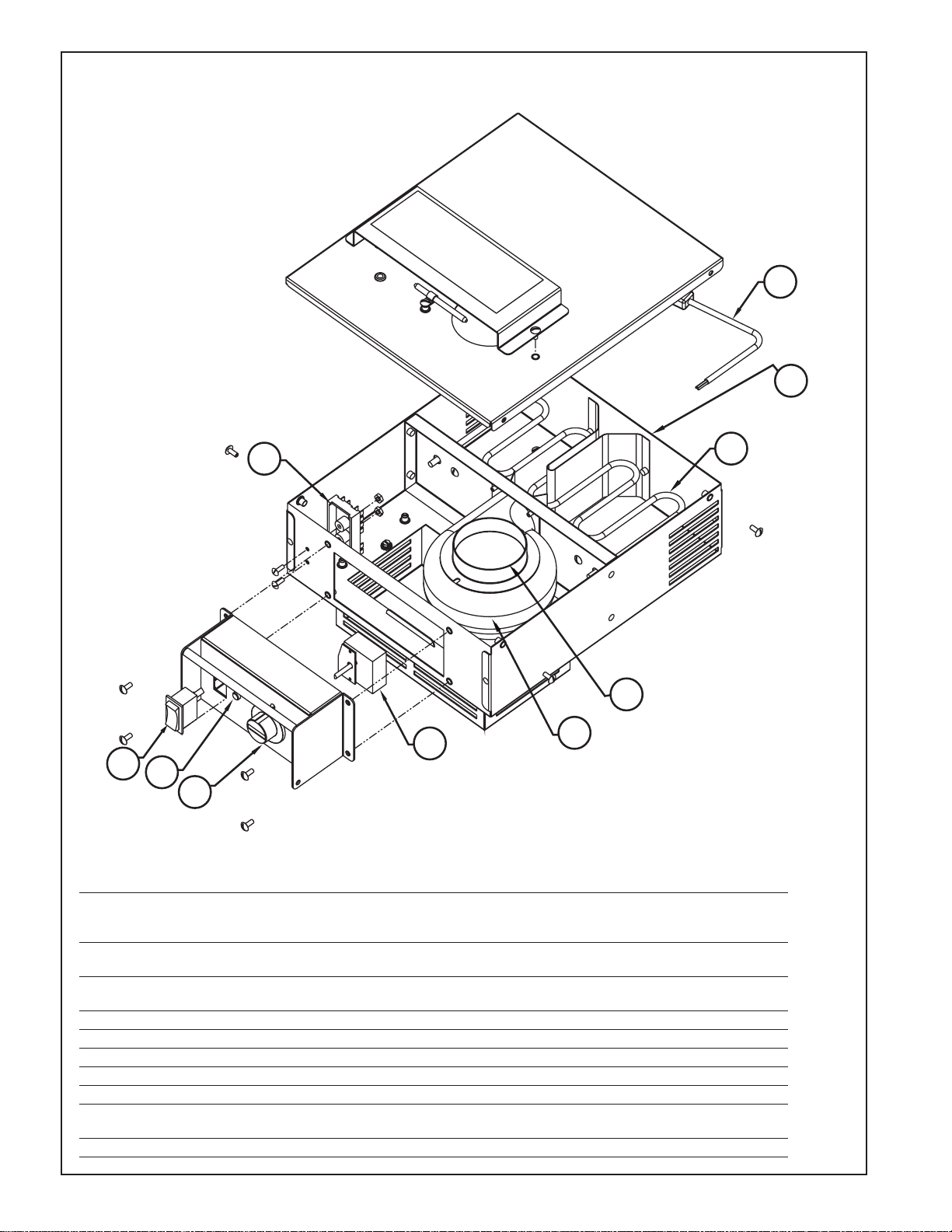
Heat Module — BQ1700 and BQ1700X
1
8
7
6
5
4
3
2
9
10
Confirm the electrical rating of the cabinet before ordering components.
REPLACEMENT PARTS LIST
Item No. Part No. Description
1 RP15A-MODCORD 22" MODULE CORD, 120V, 15 AMP
RP20A-MODCORD 22" MODULE CORD, 120V, 20 AMP
RP220-MDLCRD 22" MODULE CORD, 220V, 15 AMP
2 RPC13-166 HEAT ELEMENT, 120V 1650W
RPC13-167 HEAT ELEMENT, 220V 1650W
3 RPHM20-2103 BLOWER, 120V
RPHX20-2103 BLOWER, 220V
4 RPC13-129 THERMOSTAT
5 RPC06-313 CONTROL KNOB
6 RPC13-245 RED INDICATOR LIGHT
7 RPC13-127 POWER SWITCH
8 RPC13-096 TERMINAL BLOCK
9 RPC13-083 STRAIN RELIEF, 15 AMP CORD
RPC13-098 STRAIN RELIEF, 20 AMP CORD
10 RPC11-191 INTAKE COLLAR
10
Page 12
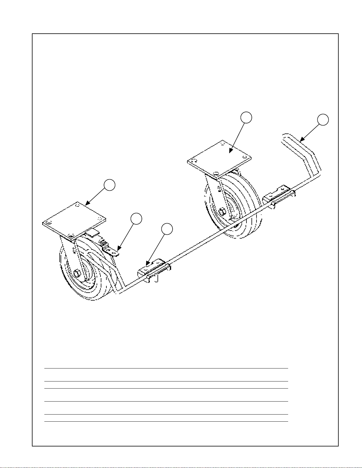
3
5
2
4
1
E. SWIVEL-LOCK CASTER SYSTEM
REPLACEMENT PARTS DIAGRAM
REPLACEMENT PARTS LIST
Item No. Part No. Description
1 RPSL-DDWELD DOUBLE DOOR CABINET SWIVEL-LOCK RELEASE
RPSL-SDWELD SINGLE DOOR CABINET SWIVEL-LOCK RELEASE
2 RPSL-RETAIN RELEASE RETAINER BRACKET
3 RPSL6-CASTER 6" SWIVEL-LOCK CASTER
RPSL8-CASTER 8" SWIVEL-LOCK CASTER
4 RPC02-197 6" SWIVEL CASTER
RPC02-200 8" SWIVEL CASTER
5 RPSL-LOCKTAB SWIVEL-LOCK TAB AND HARDWARE
11
Page 13
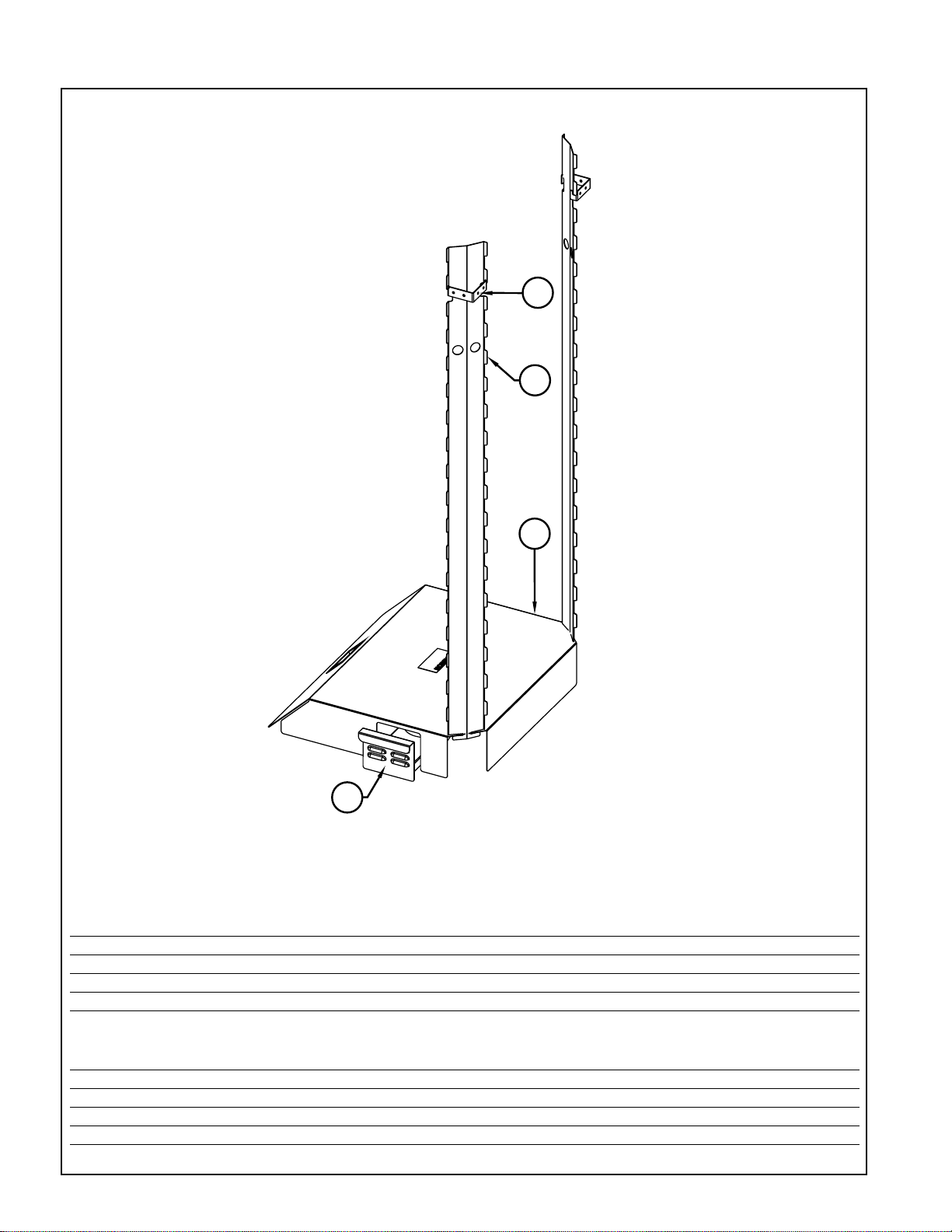
4
3
2
1
F. QUAD-HEAT REPLACEMENT PARTS DIAGRAM
REPLACEMENT PARTS LIST
CABINET MODEL #
Item
No. Description MBQ-200D-QH MBQ-180D-QH MBQ-150D-QH MBQ-120D-QH
1 CHIMNEY HANGER RPQH-HANG RPQH-HANG RPQH-HANG RPQH-HANG
2 CHIMNEY RPQH-200CHIM RPQH-180CHIM RPQH-150CHIM RPQH-120CHIM
3 CANNED FUEL DRAWER RPQH-DRAWER RPQH-DRAWER RPQH-DRAWER RPQH-DRAWER
4 FLUE RPQH-DDFLUE RPQH-DDFLUE RPQH-DDFLUE RPQH-DDFLUE
CABINET MODEL #
Item
No. Description MBQ-180-QH MBQ-144-QH MBQ-120-QH MBQ-90-QH MBQ-72-QH
1 CHIMNEY HANGER RPQH-HANG RPQH-HANG RPQH-HANG RPQH-HANG RPQH-HANG
2 CHIMNEY RPQH-180CHIM RPQH-180CHIM RPQH-150CHIM RPQH-150CHIM RPQH-120CHIM
3 CANNED FUEL DRAWER RPQH-DRAWER RPQH-DRAWER RPQH-DRAWER RPQH-DRAWER RPQH-DRAWER
4 FLUE RPQH-180FLUE RPQH-144FLUE RPQH-144FLUE RPQH-90FLUE RPQH-90FLUE
12
Page 14
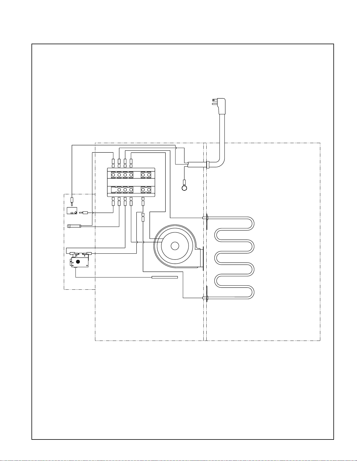
VI. WIRIng sCHemaTICs
POWER
SWITCH
THERMOMETER
BULB
HEAT
THERMOSTAT
2317221621
15
24
18
201419
13
11 10 912 8 7
5 4 36 2 1
18
6
INDICATOR
LIGHT
WHITE
23
5
4 3
2
8
22
BLOWER
ELEMENT
TERMINAL BLOCK
BLACK
GREEN
GROUND SCREW
(GREEN COLOR)
21
22" POWER SUPPLY CORD
4 2
18
5
6
21
8
STRAIN RELIEF
BQ1700 MODULE WIRING DIAGRAM
13
Page 15
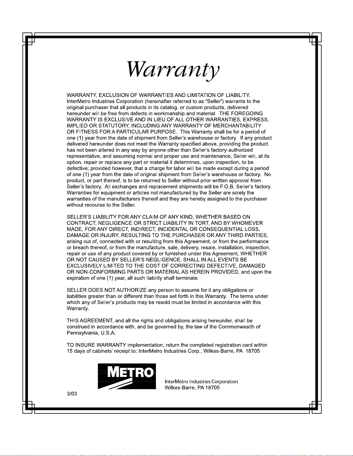
InterMetro Industries Corporation (hereinafter referred to asSeller) warrants to the
®
14
Page 16
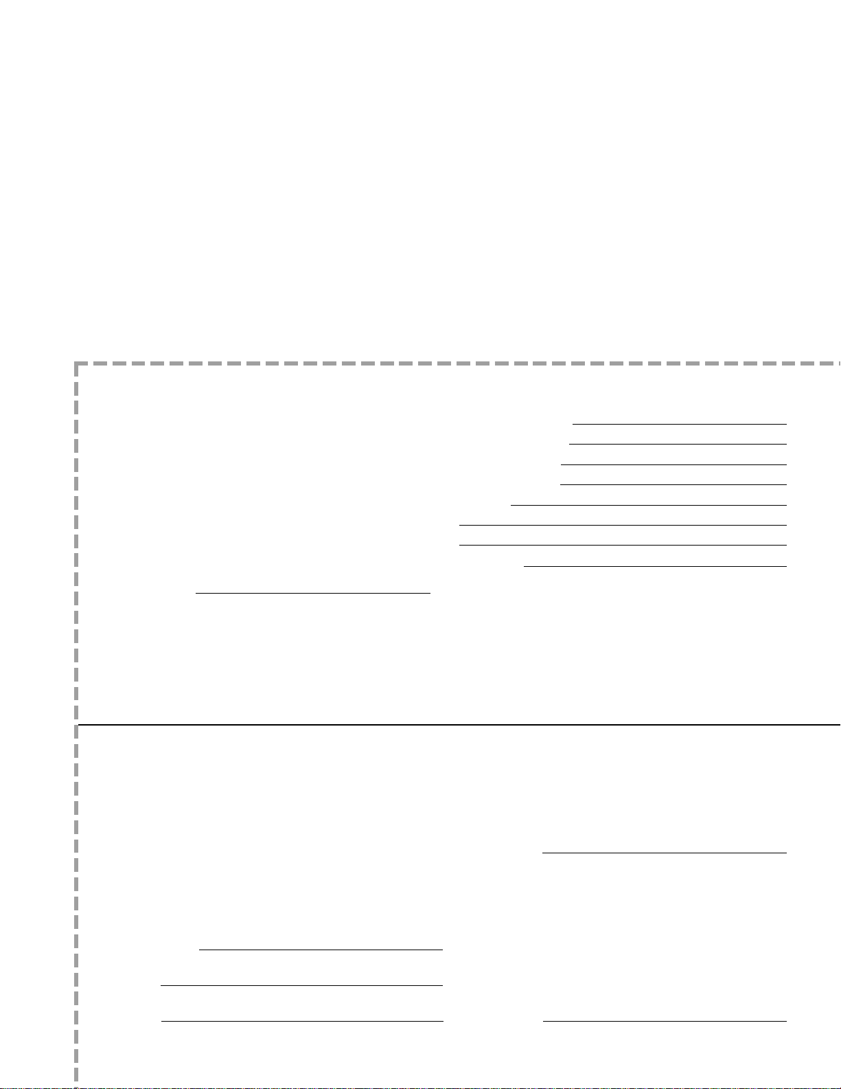
Thank you for purchasing a Metro Heated Banquet
Cabinet. We are certain you will be more than
satisfied with its quality and performance. Please fill in
the warranty information space below so we may register
your warranty. Also, so that we may learn more
about our customers and hopefully be of continued
service in the future, please take a moment
to fill in the customer information space below.
Thank You
CUT ALONG DOTTED LINE
CUSTOMER INFORMATION
1. Which one of the following best describes
your establishment?
a. ❑ Full-Service Restaurant
b.❑ Banquet Hall
c. ❑ Hotel/Motel
d. ❑ Hospital/Nursing Home
e. ❑ College/University
f. ❑ School
g. ❑ Employee Feeding
h. ❑ Other
FOLD HERE — DO NOT DETACH
2. Please indicate the two product benefits that
were of major interest to you.
CUT ALONG DOTTED LINE
a. ❑ 3-point handle control.
b. ❑ Swivel-lock caster system maneuverability.
c. ❑ Quad-Heat Canned Fuel System performance.
d. ❑ Easy-to-clean, removable heating module.
e. ❑ Hands-free access kick-latch.
f. ❑ Control panel information (timer/white-board).
g. ❑ Reliable design and construction.
h. ❑ Flexibility provided by mini-rack accessory.
i. ❑ Other
WARRANTY INFORMATION:
Cabinet Model No.
Module Serial No.
Date Purchased
Customer Name
Address
Phone No.
For warranty coverage, this card
must be returned to Metro.
3. Main factor that led to your decision to
purchase this product?
a. ❑ Product operating and functional features
b. ❑ Overall quality
c. ❑ Price
d. ❑ Availability
e. ❑ Other
4. Three sources that led to the purchase of
his product — in the order of their impact
(1 — being most impact; 3 — being least impact).
a. ❑ Trade Journal Ad
b ❑ Trade Show
c. ❑ Sales Call
d. ❑ Direct Mail
e. ❑ Previous Purchase
f. ❑ Other
15
Page 17
WILKES-BARRE PA 18705-9968
P O
BOX A
ATTN: CUSTOMER SERVICE
INTERMETRO INDUSTRIES CORPORATION
POSTAGE WILL BE PAID BY
F IRS T-C LA SS PER MI T NO . 1 21 W IL KE S- BA RR E, PA
BUSINESS REPLY MAIL
UNITED STATES
IN THE
IF MAILED
NECESSARY
NO POSTAGE
FOLD HERE — DO NOT DETACH
STAPLE HERE
STAPLE HERE
16
STAPLE HERE
Page 18

InterMetro Industries Corporation
North Washington Street, Wilkes-Barre, PA 18705
For Product Information Call: 1-800-433-2232
Visit Our Web Site: www.metro.com
L01-399
08
Rev. C 2
Information and specifications are subject to change
without notice. Please confirm at time of order.
/
 Loading...