

Page 1
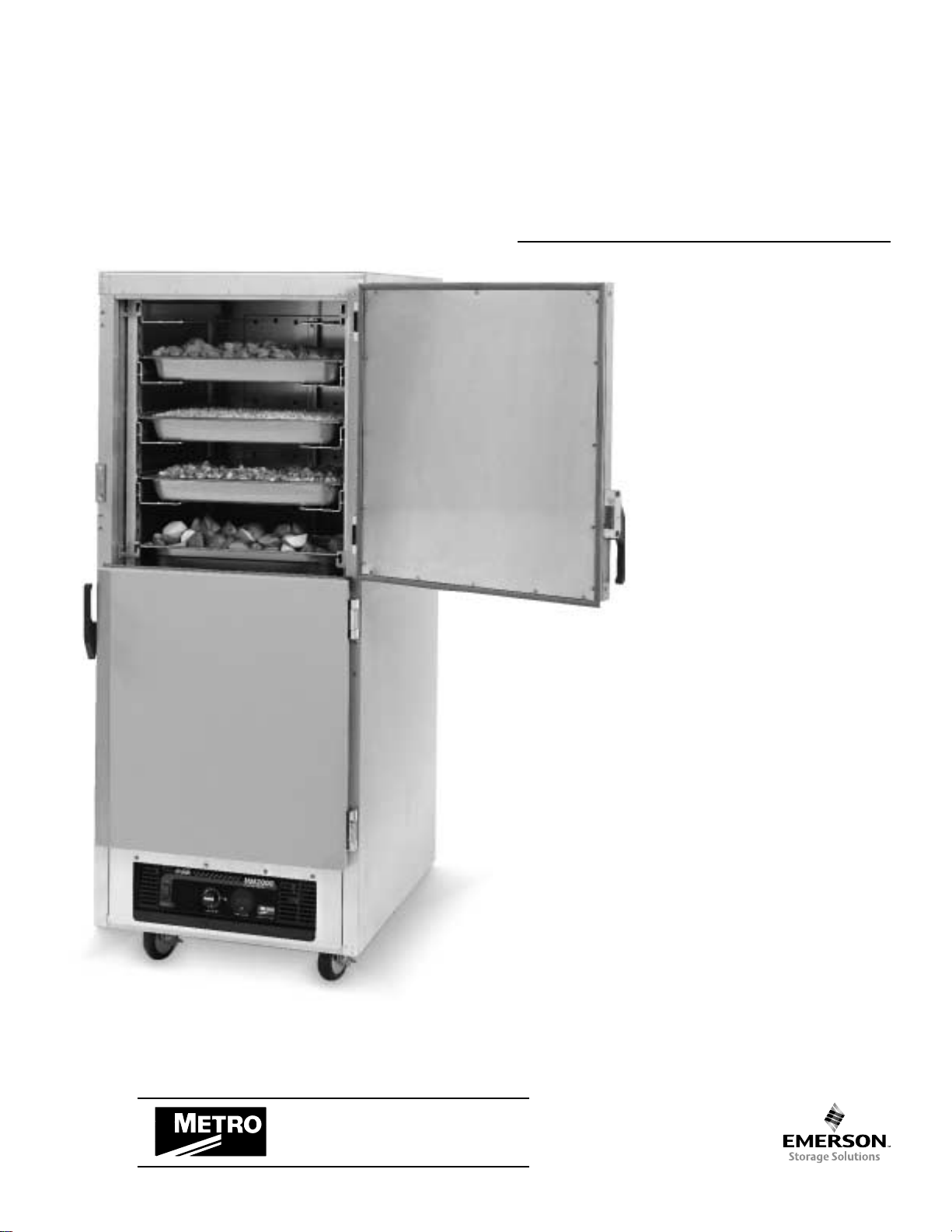
199 Series
Rev . 3/99
USER
MANUAL
FOR THE
METRO
C199 AND
FL199
SERIES
INSULATED
HEATED
CABINETS
®
®
InterMetro Industries Corporation
Wilkes-Barre, PA 18705
570-825-2741
Recommended Food Holding
Guidelines Listed on pages 5 & 6.
Page 2
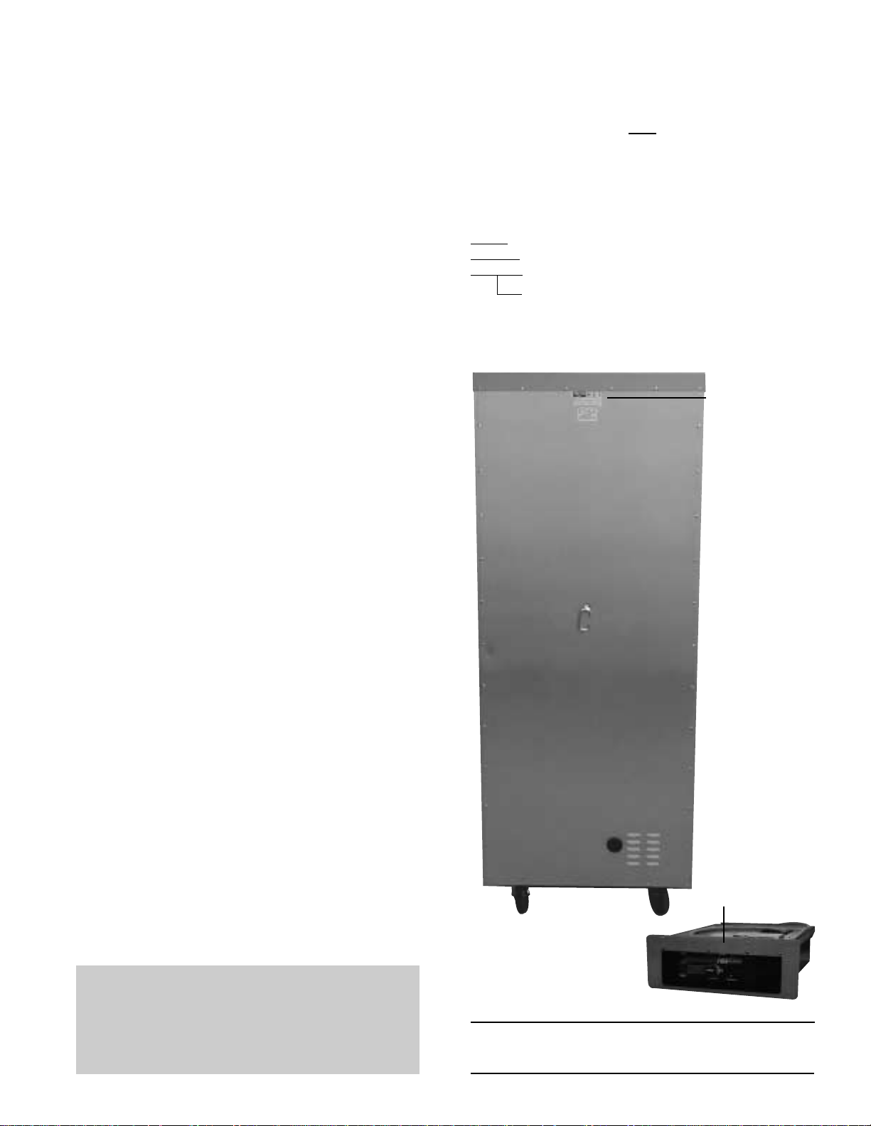
TABLE OF CONTENTS
SAMPLE OF CABINET LABELING
SECTION PAGE
I. Introduction
A. Identifying Your Cabinet ...............................1
B. Features ....................................................... 2
II. Operating Instructions
A. Reversible Doors ......................................... 2
B. Slide Rack Assemblies ................................ 2
C1. HM2000 Holding Module ............................. 3
C2. FL2000 High Humidity Holding .................... 4
III. Food Holding Guidelines
A. HM2000/HM15LW Recommended
Food Holding Guidelines ...................... 5 & 6
IV. Cleaning Instructions
A. Specific Cleaning Instructions ..................... 7
B. General Cleaning Instructions ..................... 7
V. Maintenance
A. Cabinet Maintenance ...................................7
B. Module Maintenance ................................... 7
C. Blower Motor Maintenance .......................... 7
VI. Relacement Parts, Procedures a n d
Wiring Diagrams
A. Cabinet .................................................. 8 & 9
B. Modules ..................................................... 10
HM2000
Module Replacement Parts Diagram ........ 11
Wiring Schematic ................................... 12
FL2000
Module Replacement Parts Diagram ........ 13
Wiring Schematic .................................... 14
C199-HM2000 = Full Height, Holding
C199T-HM2000 = 3/4 Height, Holding
OR
FL199-HM2000 = Full Height, High Humidity Holding
FL199H-HM2000 = 1/2 Height, High Humidity Holding
SAMPLE OF SLIDE RACK
CARTON LABELING
C4SC = Full Height
C4SC-T =3/4 Height
C4SC-H =1/2 Height
Indicates Slide Spacing
C4SC/-T/-H = Wire 3" Spacing
C8SN/-T/-H = Aluminum Fixed on 11/2" Spacing
CVSN/-T/-H = Aluminum Adjustable
▼
LOCATION
OF CABINET
MODEL
NUMBER
I. INTRODUCTION
A. IDENTIFYING YOUR CABINET
Your cabinet assembly has been shipped in two
cartons. The first carton contains the cabinet with
module. The other carton contains the slide racks.
There are several component numbers which you
may want to record for future reference: the cabinet
model number, the module model number along
with the module serial number and the slide rack
model number. Refer to the photo at right to locate
these numbers. The slide rack model number is
located on the label affixed to the ends of the rack
carton. It is recommended that all numbers be
recorded in an appropriate place, such as at the
bottom of this page. AIso, please record the
cabinet model number and module serial number
on the Warranty Card found at the back of this
manual. Be sure to complete the remainder of the
Warranty Card and return it to Metro within fifteen
(15) days of delivery of the cabinet. Once you have
located and recorded these numbers, refer to the
sample numbers given on this page to identify the
components of your 199 series cabinet.
Cabinet Model No. ________________________
FL199-HM2000
Full Height Unit Shown
LOCATION OF
MODULE MODEL
NUMBER AND
SERIAL NUMBER
▼
Module Model No. _________________________
Module Serial No. _________________________
Slide Rack Model No. ______________________
NOTE: Please read this manual thoroughly before using your
cabinet. If you should have questions, please contact
Metro customer service department.
1
Page 3

B. FEATURES — ALL MODELS
In order to utilize your new cabinet to its full potential,
take a minute to identify the following features which
have been provided for your convenience.
• The module has been placed at the base of the
cabinet for easy accessibility and efficient operation.
• Clearly-marked control panel for easy viewing
and allowing climate adjustments without opening
the door(s).
• Removable water pan (C199) or water bottle
(FL199).
• Rear pan stop.
• Field reversible insulated and gasketed door(s).
• Easy pull adjustable magnetic door latch.
• Cord keeper at rear of cabinet which folds flat to
prevent damage to surrounding walls.
• All components — door(s), module, chimney,
slide racks — removable to permit thorough,
obstruction-free cleaning.
II. OPERATING INSTRUCTIONS
A. REVERSIBLE DOOR(S)
The door(s) on your cabinet can be reversed to
accommodate a right- or left-hand opening. The
cabinet has been shipped with the hinges
mounted on the right-hand side. To reverse, follow
the instructions listed below (read completely
before starting procedure):
1. With the doors in the closed position remove
the hinge pin by driving it out using a hammer
and a drive pin or small diameter screwdriver.
2. Once the pins are removed grasp the door
firmly and pull the latch lever, this will release
the door. Repeat the process for double door
units. Set the door(s) aside being careful not to
damage the gaskets.
3. Remove the screws from the left side of the
cabinet and set aside. Then remove the
cabinet mounted part of the hinge and remount
to the left side of the cabinet. Put the screws
removed from the left side of the cabinet, into
the remaining holes on the right side of the
cabinet. Tighten all screws before proceeding.
4. Relocate the latch plate(s) from the left side to
the right by removing the two mounting screws.
Tighten all screws before proceeding.
5. On single door units rotate the door 180
degrees and align the door mounted hinge
part with the cabinet mounted hinge part and
tap the hinge pin into place so top of pin is
flush with top of the cabinet mounted hinge
part. Invert the door latch by removing black
plastic screw covers and remove the screws
holding the latch in place.
6. On double door units rotate the top-door 180
degrees and mount in the position of the lower
door. Rotate what was the bottom-door 180
degrees and mount in the position of the top
door. Align the door mounted hinge part with
the cabinet mounted hinge part and tap the
hinge pin into place so top of pin is flush with
top of the cabinet mounted hinge part.
7. Relocate the label on the door(s). Be sure that
there are no open screw holes on the front of
the cabinet.
B. SLIDE RACK ASSEMBLIES
All models of slide racks are removable for
thorough cleaning.
On the inside of each cabinet are a series of
rack hangers. These hangers have two slots for
either an inboard or outboard rack position. To
remove the slide rack, grasp and move upward
until the pins are free of the hanger slots. To
install the racks, locate the pins over the
hangers and lower until locked into the slots.
NOTE: For an inboard rack position, use the
slots farthest away from the wall of the cabinet.
For an outboard rack position, use the slots
closest to the wall of the cabinet.
C4SC/-T/-H — Model 4 (3" Slide Spacing fixed)
The Slide Rack consists of two (2) pair of slides
and the C4SC-T and C4SC-H consist of (1) pair
of slides. The pairs can be placed in the
inboard or outboard position. The C4SC can
have one pair in the inboard position and one
pair in the outboard position. All pans are to be
bottom loaded regardless of rack position. The
following pans may be used:
Inboard Hanger Position (18" width)
Pan Size C4SC C4SC-T C4SC-H
18"x26"x25/8" 17 pans 13 pans 8 pans
14"x18"x25/8" 17 pans 13 pans 8 pans
Max. pan size: 18"x27"x25/8"
Min. pan size: 17"
Outboard Hanger Position (20" width)
C4SC C4SC-T C4SC-H
17 pans 13 pans 8 pans
14 pans 13 pans 8 pans
34 pans 26 pans 16 pans
28 pans 26 pans 16 pans
Max. pan size: 20"x27"x25/8"
Min. pan size: 19"
C8SN/-T/-H — Model 8 (11/2" Spacing-fixed)
The Model 8 Slide Rack can only be installed in the
inboard hanger position. All pans are to be lip loaded.
The following pans may be used:
Model 8 Slide Rack
C8SN C8SN-T C8SN-H Pan Size
34 pans 28 pans 17 pans 18"x26"x13/8"
2
Page 4

CVSN/-T/-H — Model V (adjustable)
The Model V Slide Rack can be installed in either an
inboard or outboard position. Center spacing on
slides can be either 3" or 41/2". Slides can be removed
by lifting upward and sliding the rivet heads out of the
keyhole slots. To install, select spacing, insert the rivet
heads into the keyhole slots and push down until
locked in the hole. All pans are to be bottom loaded
regardless of slide or rack positioning.
With the racks in the inboard position (18" width), the
following pans may be used:
3" Slide Spacing
CVSN CVSN-T CVSN-H Pan Size
16 pans 12 pans 8 pans 18" x26" x25/8"*
32 pans 26 pans 18 pans 12"x18"x25/8"*
32 pans 26 pans 18 pans 13"x18"x25/8"*
17 pans 13 pans 9 pans 14"x18"x25/8"*
Max. or combined pan size: 18"x27"x25/8”
Min. pan width: 16"
41/2" Slide Spacing
CVSN CVSN-T CVSN-H Pan Size
11 pans 9 pans 6 pans 18"x26"x41/8"
22 pans 18 pans 12 pans 12"x18"x41/8"
22 pans 18 pans 12 pans 13"x18"x41/8"
22 pans 18 pans 16 pans 14"x18"x41/8"
Max. or combined pan size: 18"x27"x41/8"
Min. pan width: 18"
With the racks in the outboard position (20" width), the
following pans may be used:
3" Slide Spacing
CVSN CVSN-T CVSN-H Pan Size
17 pans 13 pans 9 pans 15"x20"x25/8"*
34 pans 26 pans 18 pans 107/8"x193/4"x25/8"*
34 pans 26 pans 18 pans 111/8"x20"x25/8"*
17 pans 13 pans 9 pans 20"x20"x25/8"*
16 pans 12 pans 8 pans 20"x22"x25/8"*
32 pans 24 pans 16 pans 12"x20"x25/8"*
17 pans 13 pans 9 pans 20"x24"x25/8"*
Max. or combined pan size: 20"x27"x25/8"
Min. pan width: 16"
41/2" Slide Spacing
CVSN CVSN-T CVSN-H Pan Size
11 pans 9 pans 6 pans 15"x20"x41/8"
22 pans 18 pans 12 pans 107/8"x193/4"X41/8"
22 pans 18 pans 12 pans 111/8"x20"x41/8"
11 pans 9 pans 6 pans 20"x20"x41/8"
11 pans 9 pans 6 pans 20"x22"x41/8"
22 pans 18 pans 12 pans 12"x20"x41/8"
11 pans 9 pans 6 pans 20"x24"x41/8"
Max. or combined pan size: 20"x27"x41/8"
Min. pan width: 18"
*The top rack level is usable if the pan and product do not
exceed 2" in height.
If this condition exists, an extra pan can be held.
C1. HM2000 HOLDING MODULE
For Recommended Holding T emperatures,
see HM2000 guidelines on page 6.
When equipped with a holding module, your
cabinet is designed to maintain the
temperature of HOT prepared foods. The
holding module is equipped with a
thermostatically controlled heater, a blower
for air circulation and a water pan. A POWER
switch is provided with a red light to indicate
when the unit is switched ON. Beside the
POWER switch is the TEMPERATURE
thermostat and its yellow indicator light.
A seven foot, three wire grounded lead cord
is supplied fixed to the module. The cord
cannot be separated from the module, so
be careful when passing the cord through
the cabinet back panel. Likewise, when
installing the module into a cabinet, the cord
must first be fed through the opening in the
cabinet back panel.
1. With the POWER switch OFF, plug the cord
into a standard grounded 20 amp, 125VAC
grounded receptacle on an individual
branch circuit.
CAUTION: THE WATER PAN MUST BE IN
PLACE DURING MODULE OPERATION.
2. To introduce limited humidity, fill the 11/2-quart
capacity water pan to 1/2" from the top with
HOT clean tap water. During operation,
check the water level every 3 hours and refill
as necessary. The unit may be operated
without water if humidity is not desired.
3. Push the POWER switch to the ON position
by depressing the top of the switch. The red
POWER lens in the switch will glow and the
blower will begin circulating air. Note: This
is not a foot switch. Using it as a foot switch
can damage the switch and make the
cabinet inoperable.
4. Turn the TEMPERATURE thermostat to a setting
of 10. The holding unit is now in operation.
5. After allowing the cabinet to PREHEAT FOR
APPROXIMATELY 45/60 MINUTES, reduce
the thermostat setting to 6/8. In a room of
average temperature (72°F), this should
provide 150°- 170°F. Adjustments to the
temperature may be made as necessary.
THIS IS A HOT FOOD HOLDING CABINET AND
IS NOT INTENDED TO RETHERMALIZE COLD
FOOD. MAKE SURE FOOD AND CABINET ARE
A T PROPER TEMPERA TURES BEFORE
PLACING FOOD IN THE CABINET.
NOTE: The POWER (red) light will glow as soon
as the POWER switch is switched ON and will
continue to glow until switched OFF. The yellow
indicator light will go on and off as the thermostat
cycles. The blower will operate as long as the
POWER switch is ON. If the yellow light is not
illuminated, this indicates that the cabinet has
achieved the preset TEMPERA TURE level, NOT
that the unit has been switched OFF.
3
Page 5

It is not necessary at the end of the operating
day to disrupt the TEMPERATURE setting in
order to turn the unit OFF. By switching the
POWER switch to OFF, the unit is no longer
operating. By switching the POWER switch to
ON when resuming operations, the cabinet
setting will be at the previous set point.
C2. FL2000 HIGH HUMIDITY HOLDING
MODULE
For Recommended Holding T emperatures,
see FL2000 guidelines on page 5.
When equipped with a high humidity module
your cabinet is designed to maintain the
temperature and moisture content of
prepared foods. The module has controls
for heat and humidity, a blower for air
circulation and a removable water bottle.
A POWER on/off switch is provided with a red
light to indicate when the unit is ON. Beside
the POWER switch are the TEMPERATURE
and HUMIDITY control knobs and yellow
lights to indicate when each element is on.
A seven foot, three wire, grounded cord is
supplied as part of the module.
1. With the POWER switch OFF, plug the cord
into a standard 20 amp, 125VAC grounded
receptacle on an individual branch circuit.
THE WATER BOTTLE SHOULD BE IN
PLACE PRIOR TO AND DURING MODULE
OPERATION. Push the bottle in until you hear
a click (indicating the valve half in the water
bottle has engaged the valve half in the
control panel).
2. To introduce humidity, fill the 2 gallon
capacity water bottle to the fill spout with
clean, cold tap water. If you have hard tap
water, use distilled water in the bottle. During
operation, check the water level every
several hours and refill as necessary. The
unit may be operated without water if
humidity is not desired. If humidity is not
required, turn the humidity knob to the OFF
position. There is no need to remove any
water from the bottle. During extended
periods of operation without humidity, the
bottle should be emptied of water. The next
time humidity is required, clean and rinse the
bottle and install it into the cabinet before
refilling with clean, cold water. If the cabinet
is to be used for transporting food, empty the
water bottle first.
3. Push the POWER switch to the ON position
by depressing the top of the switch. The red
POWER lens in the switch will glow and the
blower will begin circulating air. The
thermometer display will show cabinet
temperature. Note: This is not a foot
switch. Using it as a foot switch can damage
the switch and make the cabinet inoperable.
4. The thermometer display shows the current
temperature in the cabinet. The temperature
setting can be adjusted by turning the
temperature knob clockwise to increase and
counter-clockwise to decrease temperature.
5. The humidity can be adjusted by turning the
humidity knob clockwise to increase and
counter-clockwise to decrease humidity. If
you wish to hold food without using humidity,
turn the Humidity control to MIN. This will
prevent the cabinet from introducing
additional humidity.
6. A buzzer alarm is located in the module to
indicate low water level. Refilling the bottle will
turn the buzzer off. If the bottle is not filled
promptly, the humidity will begin dropping off
in the cabinet. The bottle may be filled
through the pour spout. The maximum fill level
is to the fill opening. Turning the Humidity
knob to MIN will stop the buzzer until water
can be added. Then reset the humidity knob
to the desired position.
7. Allow the cabinet APPROXIMATELY 45 to 60
MINUTES to reach the desired settings. THIS
IS A HOT FOOD HOLDING CABINET AND
IS NOT INTENDED TO RETHERMALIZE
COLD FOOD. MAKE SURE FOOD
AND CABINET ARE AT PROPER
TEMPERA TURES BEFORE PLACING
FOOD IN THE CABINET.
NOTE: The POWER switch red light will glow
as soon as the POWER switch is turned ON.
The yellow indicator light to the left of each
control knob will go on and off as controls
cycle the temperature and/or humidity
elements. The blower will operate as long as
the POWER switch is ON. If the yellow
indicator light for the temperature control
knob is not illuminated, this indicates that the
cabinet has achieved the set
TEMPERATURE. The light for the humidity
control knob will continue to cycle on and off
at a regular rate to maintain the desired
humidity. It is not necessary at the end of the
operating day to disrupt the TEMPERATURE
or HUMIDITY settings in order to turn the unit
OFF. By pushing the POWER switch to OFF,
the unit is no longer operating. By pushing
the POWER switch to ON when resuming
operations, the cabinet settings will be at the
previous settings.
8. The module can be removed for routine
cleaning. WHEN CLEANING, DO NOT
SPRAY OR POUR WATER ON THE MODULE
AND DO NOT IMMERSE THE MODULE IN
WATER. WIPE WITH A DAMP CLOTH AND
DRY WITH A TOWEL. Turn the module off
and remove the water bottle (this will allow
the humidity generator to drain), racks and
chimney. Remove the module from the
cabinet by lifting the front up enough to clear
the module slide detents, then pull the
module from the cabinet, grasping it with
both hands as it clears the cabinet. The cord
cannot be separated from the module, so be
careful when passing the cord through the
cabinet back panel.
4
Page 6

9. To install the module, reverse step 8. When
installing the module into the cabinet, the
cord must be fed through the opening in the
cabinet back panel. Be careful that the seals
on the side of the module go inside the
module slides.
To descale the humidity generator:
To clean the humidity generator, use a
commercially available descaling solution
that is compatible with the stainless steel
humidity generator and the aluminum
cabinet interior. Pour the descaling solution
into the water bottle, using the
manufacturer’s recommended dilution. With
the bottle connected to the module, run the
humidity generator at the maximum humidity
setting for the manufacturer’s recommended
time. Then, shut off the module, remove the
water bottle and allow all the solution to drain
out of the module quick disconnect valve.
Empty the water bottle, and refill with clean
water and a cup of baking soda and reinstall
the bottle. Run the cabinet for another 30
minutes with the humidity generator at the
maximum humidity setting. Again, shut off
the module, remove the water bottle,
allowing all the water to drain out of the front
panel quick disconnect valve. Empty the
water bottle and rinse; replace the bottle into
the cabinet and refill with clean, cold water.
The cabinet is now ready to use.
III. FOOD HOLDING GUIDELINES
A. FL2000 Recommended Food Holding Guidelines
Food Product Covered/Uncovered Temperature Setting °F* Moisture Setting
Baked Fish Uncovered 175 Med/High
Baked Potatoes Uncovered 180 Off
Biscuit Uncovered 180 Medium
Broccoli Covered 170-175 High
Chicken Nuggets Uncovered 175 Off
Corn on the Cob Covered 170-175 High
Croissants Uncovered 175 Medium
Egg Patties Covered 180 High
French Fries** Uncovered 185 Off
Fried Chicken Uncovered 180-185 Off
Fried Fish Uncovered 180 Off
Hamburgers Covered 180 Medium
Lasagna Covered 185 High
Mashed Potatoes Covered 175 High
Mixed Veggies Covered 170-175 High
Pancakes Covered 175 Medium
Pasta Covered 180 High
Peas Covered 170-175 High
Pizza Uncovered 175-180 High
Roast Beef Uncovered 170-180 Medium
Roast Pork Uncovered 170-180 Medium
Scalloped Potatoes Covered 175 High
Strip Steak Uncovered 160-170 Medium
Turkey Uncovered 170-180 Medium
Waffles Covered 175 Medium
Whole Chicken Uncovered 170-180 Medium
*Temperatures are guidelines only, based on opening cabinet doors every 15 minutes.
**Lightly salted for best quality.
Developed by Penn State University School of Hotel, Restaurant, and Recreation Management
5
Page 7

III. FOOD HOLDING GUIDELINES
A. HM2000/HM15LW Recommended Food Holding Guidelines
Food Product Covered/Uncovered Temperature Setting °F*
Baked Fish Uncovered 175
Baked Potatoes Uncovered 180
Biscuit Uncovered 180
Broccoli Covered 170-175
Chicken Nuggets Uncovered 175
Corn on the Cob Covered 170-175
Croissants Uncovered 175
Egg Patties Covered 180
French Fries** Uncovered 185
Fried Chicken Uncovered 180-185
Fried Fish Uncovered 180
Hamburgers Covered 180
Lasagna Covered 185
Mashed Potatoes Covered 175
Mixed Veggies Covered 170-175
Pancakes Covered 175
Pasta Covered 180
Peas Covered 170-175
Pizza Uncovered 175-180
Roast Beef Uncovered 170-180
Roast Pork Uncovered 170-180
Scalloped Potatoes Covered 175
Strip Steak Uncovered 160-170
Turkey Uncovered 170-180
Waffles Covered 175
Whole Chicken Uncovered 170-180
*Temperatures are guidelines only, based on opening cabinet doors every 15 minutes.
**Lightly salted for best quality.
Developed by Penn State University School of Hotel, Restaurant, and Recreation Management
6
Page 8

IV. CLEANING INSTRUCTIONS
CAUTION
AT NO TIME SHOULD THE MODULE OR
CABINET BE WASHED OR FLOODED WITH
WATER OR LIQUID SOLUTION. NEVER
STEAM CLEAN. SEVERE DAMAGE OR
ELECTRICAL HAZARD COULD RESULT.
1. Turn off master switch.
2. Disconnect the unit from its power source.
WARNING
ALLOW THE UNIT TO COOL BEFORE
CLEANING, AS THE INTERIOR OF THE CABINET
MAY BE HOT ENOUGH TO BURN. ALSO ALLOW
THE WATER IN THE PAN (C199) OR BOTTLE
(FL199) TO COOL BEFORE REMOVAL.
3. Open the door(s) and remove the slide racks
and chimney.
4. If there is water in the pan or bottle, remove
and empty.
5. Remove the module from the cabinet by
lifting up the front enough to clear its detent,
then pull the module away from the cabinet.
The power cord slips through the clearance
hole at the rear of the cabinet.
6. Do not use abrasive cleaners. For every
cleaning method, best results are always
obtained when the cleaner and technique
are matched to the soil conditions involved.
Contact your detergent representative to
ensure the cleaning product being used is
recommended for use on natural and epoxy
coated aluminum. FOLLOW THE
MANUFACTURER’S DIRECTIONS ON
CLEANERS. NEVER MIX CLEANERS.
7. After cleaning, replace all components.
Make sure the slide racks and chimney are
seated in the hangers correctly.
A. SPECIFIC CLEANING INSTRUCTIONS
1. When cleaning, do not spray or pour water
on the module and do not immerse the
module in water. Wipe with a damp cloth and
dry with a towel. Special attention should be
paid to keeping the air-inlet area and the
controls area free of dirt build-up.
2. Do not neglect to clean the under-chassis
area, especially the area above each caster.
3. The cabinet or component(s) must be
thoroughly rinsed to remove any residue that
may stain the materials.
4. When choosing a cleanser, make sure the
cleanser manufacturer recommends its use
on natural and epoxy-coated aluminum.
B. GENERAL CLEANING INSTRUCTIONS
1. LIGHT SOIL
If routine (daily) cleaning is practiced, a mild
soap and warm water should be sufficient to
keep the unit clean.
2. HEAVIER SOIL
If cleaning has been postponed, solvent or
emulsion type cleaners that can be applied
with bare hands will give excellent results.
Such cleaners are available under various
brand names and detergent suppliers can
recommend materials appropriate for use on
natural and epoxy-coated aluminum.
NOTE: For every cleaning method, best results
are always obtained when the cleaner and
technique are matched to the soil conditions
involved. To ensure using the proper cleaner for
natural and epoxy-coated aluminum, contact
your detergent representative.
V. MAINTENANCE
A. CABINET MAINTENANCE —
ALL MODELS
Your 199 series cabinet has been designed
to require very little maintenance. With
normal use, cleaning is the only form of
maintenance that need be done on a regular
basis. Keeping the casters free of dirt buildup will go a long way in prolonging their life.
If your cabinet is rolled over rough surfaces
or transported over-the-road, the various
threaded fasteners, i.e., screws and nuts,
should be periodically inspected and
tightened if necessary, particularly the
transport latch, hinge and caster fasteners.
B. MODULE MAINTENANCE
The module in the base of your cabinet has
also been designed to require very little
maintenance. With normal use, cleaning is
the only form of maintenance that need be
done on a regular basis. When cleaning, do
not spray or pour water on the module and
do not immerse the module in water. Wipe
with a damp cloth and dry with a towel.
Keeping vital areas such as the air-inlet area
and the controls area free of dirt build-up will
go a long way in prolonging the life of the
electrical components. No maintenance is
required on the electrical components.
C. BLOWER MOTOR MAINTENANCE
The blower motor bearings should be
lubricated annually.
1. To gain access to the motor, follow the
instructions listed on page 10.
2. Remove the (2) rubber plugs, (1) located
at each end of motor.
3. Apply 6 drops of a SAE 20 non-detergent
oil to each bearing and re-install plugs.
4. Re-assemble module.
7
Page 9
VI. REPLACEMENT PARTS,
PROCEDURES AND
WIRING DIAGRAMS
A. CABINET — ALL MODELS
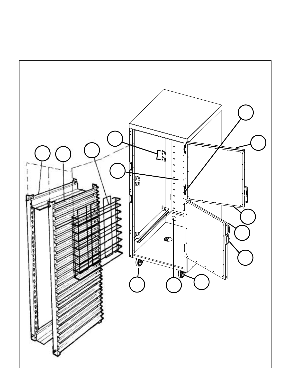
Refer to the Cabinet Replacement Parts Diagram on
next page to identify the replacement parts.
C199 Series Cabinet Replacement Parts Diagram
(see page 9 for parts list)
9
16
13
10
28
19
1
5
2
8
23
25
8
22
Page 10

CABINET REPLACEMENT PARTS LIST
(1/2 & 3/4 height cabinet parts not shown)
Item No. Part No. Description
1 RPC199P-1102T Top Door
2 RPC199P-1102B Bottom Door
3 RPC199HP-1102 Door (1/2 height cabinet)
4 RPC199TP-1102 Door (3/4 height cabinet)
5 RPC06-809 Gasket (double door units)
6 RPC06-811 Gasket (1/2 height cabinet)
7 RPC06-810 Gasket (3/4 height cabinet)
8 RPC14-118 Door Latch (strike plate included)
9 RPC14-119 Door Hinge (complete assembly)
10 C4SC C4SC Rack (full height cabinet)
11 C4SC-T C4SC-T Rack (3/4 height cabinet)
12 C4SC-H C4SC-H Rack (1/2 height cabinet)
13 C8SN C8SN Rack (full height cabinet)
14 C8SN-T C8SN-T Rack (3/4 height cabinet)
15 C8SN-H C8SN-H Rack (1/2 height cabinet)
16 CVSN CVSN Rack (full height cabinet)
17 CVSN-T CVSN-T Rack (3/4 height cabinet)
18 CVSN-H CVSN-H Rack (1/2 height cabinet)
19 RPC175-1108 Chimney (full height cabinet)
20 RPC199H-1108 Chimney (1/2 height cabinet)
21 RPC199T-1108 Chimney (3/4 height cabinet)
22 B5DNB Caster With Brake
23 B5DN Caster Without Brake
24 RPC06-179A Drip Trough Pan — Plastic (not shown)
25 RPC13-106 Snap Bushing
(2 required for entire cabinet)
26 RPCAB-HBMPR Handle Bumper (not shown)
27 RPC06-067 Cabinet Bumper (not shown)
28 RPHANG-KIT Rack Hanger Kit (2 right-hand and 2 left-hand hangers)
9
Page 11

B. MODULE
Your module has been designed to be userservicable, assuming a basic knowledge of
the operation of electrical devices. This
section has been written to guide the user
step by step, and in layman’s terms, through
the dismantling and servicing of the module.
Before attempting to service your module,
read the appropriate Module Repair
Procedures (found elsewhere in this section)
thoroughly. If you do not understand the
Repair Procedures or prefer not to service
your module yourself, or if your warranty is
still in effect, please contact our Customer
Service Department for the factory
authorized service agency nearest you.
The lead cord plug configuration designates
whether your module uses a 15 or 20 amp
service. Refer to the illustration below to
identify the two different plugs.
15 AMP PLUG 20 AMP PLUG
HM15LW HM2000/FL2000
MODULE MODULE
c. Remove the water pan/water bottle and
drain water.
d. Unfasten the electrical cover by removing
the three screws along the front of the
module and the two screws along each
edge of the module. Retain this hardware
for re-assembly.
e. Open the module by raising the
component chassis from the electrical
cover and placing the chassis top down
on a dry, non-flammable work surface. IF
NECESSARY TO RECONNECT THE
OPENED MODULE TO A POWER
SOURCE, PRACTICE EXTREME CAUTION
SO AS NOT TO RECEIVE ELECTRICAL
SHOCK FROM EXPOSED COMPONENTS.
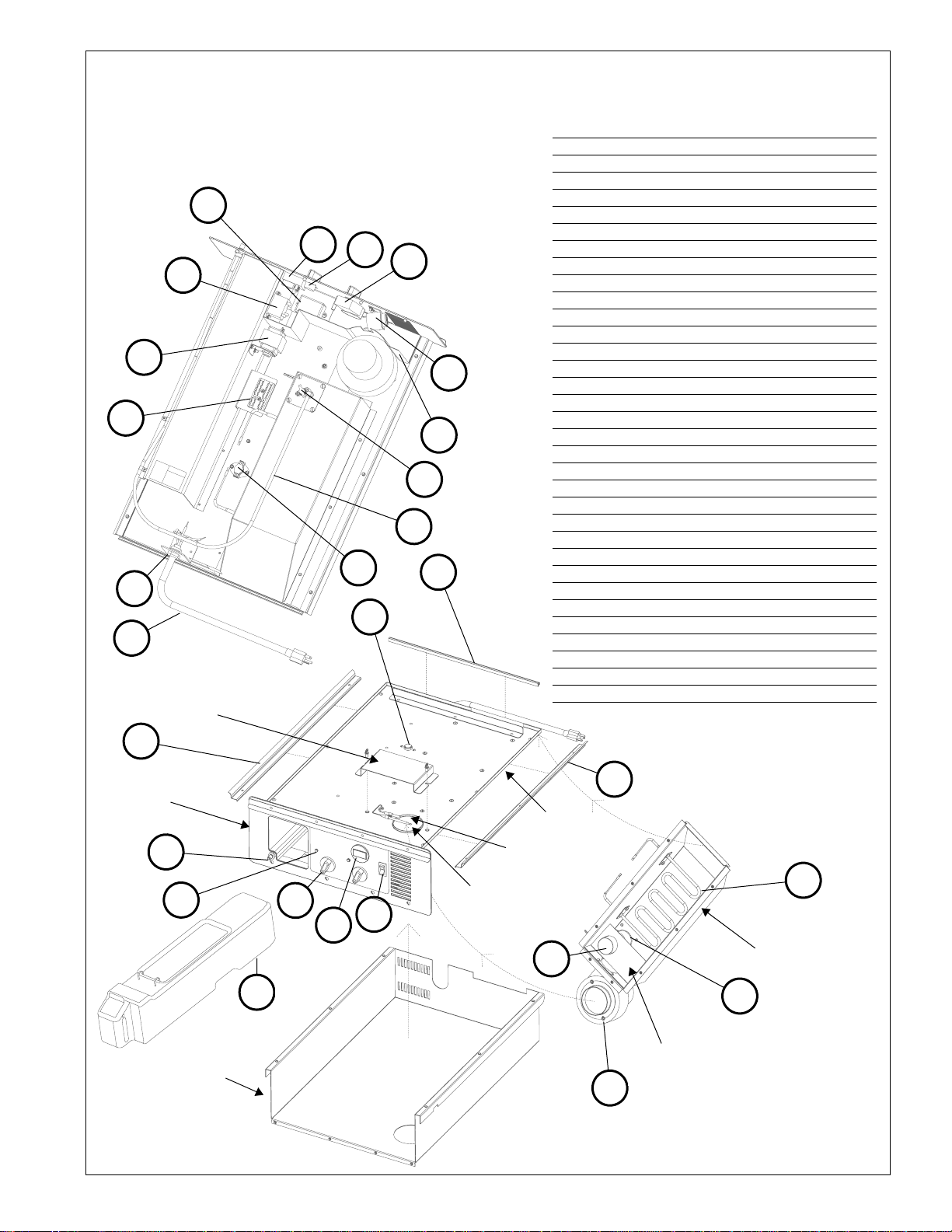
2. Refer to the appropriate Module
Replacement Parts Diagram to identify the
internal components. Determine
malfunctioning component(s) by electrical
diagnostic procedures.
3. After servicing, be sure to verify the routing
of each wire with the wiring schematic
before installing electrical cover and
connecting module to power source. Be sure
that the thermostat sensor tube does not
contact any electrical connections.
4. Assemble components using retained
hardware, making sure that no wires are
pinched between the cover and the
component chassis.
5. Install water pan/water bottle. Then, feed
cord through clearance hole in cabinet and
slide module into cabinet.
CAUTION: IT IS IMPORTANT THAT ALL
SAFETY PRECAUTIONS PERTAINING TO
THE SERVICING OF ELECTRICAL
DEVICES BE OBSERVED AT ALL TIMES.
1. Dismantle your module for servicing per the
following instructions.
NOTE: To replace the Thermostat and
Humidity Knobs, or water pan/water bottle, it
is not necessary to dismantle the module.
a. Make sure the lead cord is not plugged
into an outlet. Be certain that the module
and any water in the water pan has
cooled to a temperature safe for handling.
b. Remove module by lifting the front enough
to clear the detent, then pull the module
from the cabinet, grasping it with both
hands as it clears the cabinet. The cord
should slip through the clearance hole in
the back of the cabinet.
10
Page 12
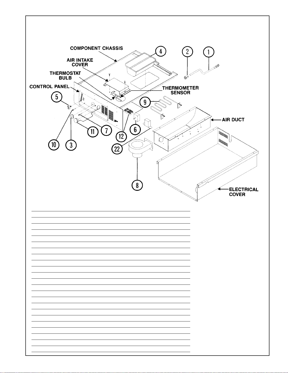
Holding Module Replacement Parts Diagram
REPLACEMENT PARTS LIST
Item No. Part No. Description
1 RPC13-017 Power Cord — 15 AMP (HM15LW only)
2 RPC13-083 Strain Relief — 15 AMP (HM15LW only)
3 RPC06-313 Thermostat Knob
4 RPHM20-PAN Water Pan
5 RPC13-127 Power Switch
6 RPC13-129 Temperature Thermostat
7 RPC13-105 Yellow Indicator Light
8 RPHM20-2103 Circulating Blower
9 RPC13-114 Heat Element — Units with 15 Amp Plug
9 RPC13-093 Heat Element — Units with 20 Amp Plug
10 RPC13-064 Red Indicator Light
11 RPC13-181 Thermometer
12 RPC13-096 Terminal Block — Control Panel
13 RPC13-012 Ring Terminal
14 RPF02-042 Push Nut — Indicator Lights
15 RPC11-191 Blower Collar
16 RPC13-085 Wire Nuts — 12 GA
17 RPC07-044 Grommet — Thermometer Wire
18 RPC06-222 Thermostat/Thermometer Bulb Clamp
19 RPC13-027
1
/4” Spade Terminals
20 RPC13-099 Power Cord — 20 AMP
21 RPC13-098 Strain Relief — 20 AMP
22 RPC13-183 Thermometer Transformer
11
Page 13
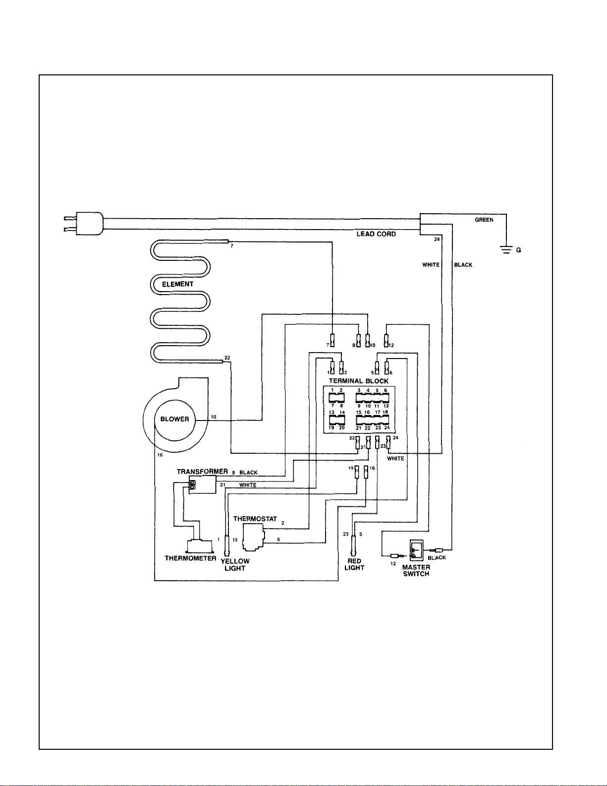
VI. WIRING SCHEMATICS
HOLDING WIRING DIAGRAM
12
Page 14
24
15
2
1
33
23
AIR INT AKE
COVER
FL2000 High Humidity Module Replacement Parts Diagram
REPLACEMENT PARTS LIST
Item # Part # Description
1 RPC13-099 Power Cord — 20 AMP
2 RPC13-098 Strain Relief — 20 AMP
3 RPC06-746 Knob
4 RPC13-132 Power Switch
5 RPC13-181 Thermometer
6 RPC13-105 Yellow Indicator Light
21
25
20
22
8
7
13
14
18
20
7 RPC11-398 Heat Shield
8 RPC13-169 Buzzer Alarm
9 RPHM20-2103 Blower
10 RPC13-166 Heat Element
11 RPC09-117 Humidity Generator
12 RPC13-167 Band Heater
13 RPC13-168 Humidity Cut-out Switch
14 RPFL-3/8TUBE Tubing
15 RPC13-096 Terminal Block
16 RPHHM-WBA Water Bottle
17 RPC15-024 Coupling
18 RPFL20-RMS Rear Seal
19 RPFL20-SMS Side Seal
20 RPC13-134 Hi-Temp Cut-out
21 RPC13-172 Percentage Timer
22 RPC13-129A Thermostat
23 RPC13-173 Relay
24 RPC13-174 Transformer
25 RPC13-171 Potentiometer
26 RPC13-012 Ring Terminal
27 RPF02-042 Push Nut — Indicator Lights
28 RPC11-191 Blower Collar
29 RPC13-085 Wire Nuts — 12 GA
30 RPC07-044 Grommet — Thermometer Wire
31 RPC06-222 Thermostat/Thermometer Bulb Clamp
32 RPC13-027
33 RPC13-183 Thermometer Transformer
1
/4" Spade Terminals
19
CONTROL
PANEL
17
6
COVER
16
19
TOP PAN
THERMOMETER
SENSOR
3
4
5
THERMOSTAT
BULB
10
AIR DUCT
11
12
DEFLECTOR
PLATE
9
13
Page 15
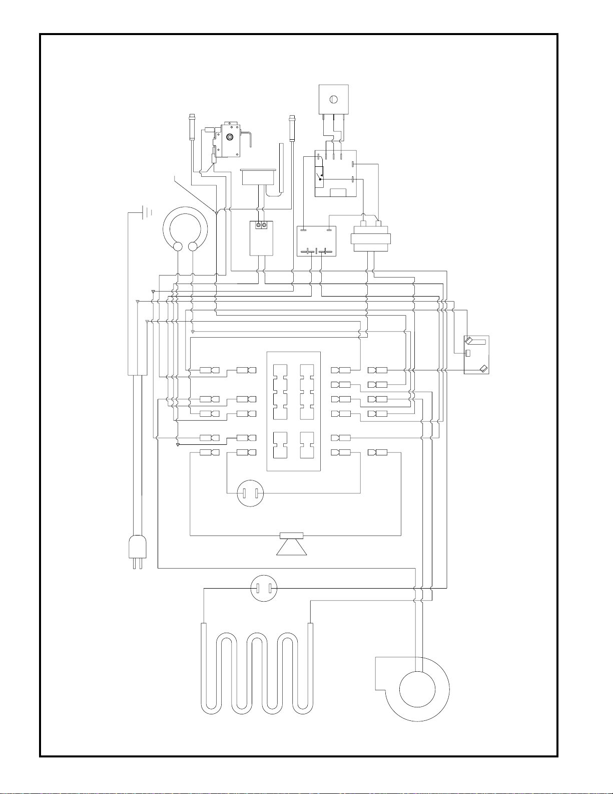
FL2000 HIGH HUMIDITY MODULE WIRING DIAGRAM
WIRE NUT (TYP)
BLACK
4
6
1
6
5
4
3
2
0
1
2
8
-
+
6V DC OUTPUT
POWER SUPPLY
THERMOMETER
TRANSFORMER 24V AC
PERCENTAGE TIMER
SWITCHING 110V AC
24V AC RELAY
100K POTENTIOMETER
CAPILLARY SENSOR
THERMOSTAT
HEAT
TIMER
PERCENTAGE
24VAC
LOAD
+
-
RED
BLUE
YELLOW
WHITE
BLACK
BLACK
BLACK
WHITE
WHITE
SWITCH
CUT-OUT
HI-TEMPERATURE
ELEMENT
WHITE
BLACK
BUZZER
BLOWER
DUCT ELEMENT
SWITCH
CUT-OUT
HI-TEMPERATURE
STEAMER
STEAMER ELEMENT
12
3
4
5
6
7
8
9
10
11
12
13
14 15
16
17
18
19
20
21
22 23
24
19
20
23
24
13
15
16 17 18
1
POWER SWITCH
LEAD CORD
7
10
12
GREEN
GROUND
TERMINAL BLOCK
THERMOMETER SENSOR
2221
9
3
2
8
4
6
14
Page 16

Thank you for purchasing a Metro Mobile Heated
Cabinet. We are certain you will be more than
satisfied with its quality and performance. Please fill in
the warranty information space below so we may register
your warranty. Also, so that we may learn more
about our customers and hopefully be of continued
service in the future, please take a moment
to fill in the customer information space below.
Thank Y ou
CUT ALONG DOTTED LINE
CUSTOMER INFORMATION
1. Which one of the following best describes your
establishment?
a.❑ Full Service Restaurant
b. ❑ Fast Food Restaurant
c. ❑ Hotel/Motel
d.❑ Hospital/Nursing Home
e. ❑ College/University
f. ❑ School
g.❑ Employee Feeding
h.❑ Other
2. Please indicate the two product benefits that
were of major interest to you.
CUT ALONG DOTTED LINE
a.❑ Accessibility to controls without opening door.
b.❑ All components within cabinet removable for
cleaning.
c. ❑ Better control of conditions in cabinet.
d.❑ Uniform environment within cabinet due to
forced air circulation, chimney design and
gasketed doors.
e. ❑ Reversible doors.
f. ❑ Aesthetic quality (styling).
g.❑ Other (in addition to above two)
WARRANTY INFORMATION:
Cabinet Model No.
Module Serial No.
Slide Rack Model No.
Date Purchased
Customer Name
Address
Phone No.
For warranty coverage, this card
must be returned to Metro.
FOLD HERE — DO NOT DETACH
3. Main factor that led to your decision to
purchase this product?
a.❑ Product operating and functional features
b. ❑ Overall quality
c. ❑ Price
d.❑ Availability
e. ❑ Other
4. Three sources that led to the purchase of
this product — in the order of their impact
(1 - being most impact; 3 - being least impact).
a.❑ Trade Journal Ad
b ❑ Trade Show
c. ❑ Sales Call
d.❑ Direct Mail
e. ❑ Previous Purchase
f. ❑ Other
15
Page 17
UNITED STA TES
IN THE
IF MAILED
NECESSARY
NO POSTAGE
WILKES-BARRE PA 18705-9968
P O BOX A
ATTN: CUSTOMER SERVICE
INTERMETRO INDUSTRIES CORPORATION
POSTAGE WILL BE PAID BY
FIRST-CLASS PERMITNO. 121 WILKES-BARRE, PA
BUSINESS REPLY MAIL
ST APLE HERE
DETACH
ST APLE HERE
FOLD HERE — DO NOT
ST APLE HERE
Page 18
Warranty
WARRANTY, EXCLUSION OF WARRANTIES AND LIMITATION OF LIABILITY.
InterMetro Industries Corporation (hereinafter referred to as “Seller”) warrants to the
original purchaser that all products in its catalog, or custom products, delivered
hereunder will be free from defects in workmanship and material. THE FOREGOING
WARRANTY IS EXCLUSIVE AND IN LIEU OF ALL OTHER WARRANTIES, EXPRESS,
IMPLIED OR STATUTORY, INCLUDING ANY WARRANTY OF MERCHANTABILITY
OR FITNESS FOR A PARTICULAR PURPOSE. This Warranty shall be for a period of
one (1) year from the date of shipment from Seller’s warehouse or factory. If any product
delivered hereunder does not meet the Warranty specified above, providing the product
has not been altered in any way by anyone other than Seller’s factory-authorized
representative, and assuming normal and proper use and maintenance, Seller will, at its
option, repair or replace any part or material it determines, upon inspection, to be
defective; provided however, that a charge for labor will be made except during a period
of one (1) year from the date of original shipment from Seller’s warehouse or factory. No
product, or part thereof, is to be returned to Seller without prior written approval from
Seller’s factory. All exchanges and replacement shipments will be F.O.B. Seller’s factory.
Warranties for equipment or articles not manufactured by the Seller are solely the
warranties of the manufacturers thereof and they are hereby assigned to the purchaser
without recourse to the Seller.
SELLER’S LIABILITY FOR ANY CLAIM OF ANY KIND, WHETHER BASED ON
CONTRACT, NEGLIGENCE OR STRICT LIABILITY IN TORT, AND BY WHOMEVER
MADE, FOR ANY DIRECT, INDIRECT, INCIDENTAL OR CONSEQUENTIAL LOSS,
DAMAGE OR INJURY, RESULTING TO THE PURCHASER OR ANY THIRD PARTIES,
arising out of, connected with or resulting from this Agreement, or from the performance
or breach thereof, or from the manufacture, sale, delivery, resale, installation, inspection,
repair or use of any product covered by or furnished under this Agreement, WHETHER
OR NOT CAUSED BY SELLER’S NEGLIGENCE, SHALL IN ALL EVENTS BE
EXCLUSIVELY LIMITED TO THE COST OF CORRECTING DEFECTIVE, DAMAGED
OR NON-CONFORMING PARTS OR MATERIAL AS HEREIN PROVIDED, and upon the
expiration of one (1) year, all such liability shall terminate.
SELLER DOES NOT AUTHORIZE any person to assume for it any obligations or
liabilities greater than or different than those set forth in this Warranty. The terms under
which any of Seller’s products may be resold must be limited in accordance with this
Warranty.
THIS AGREEMENT, and all the rights and obligations arising hereunder, shall be
construed in accordance with, and be governed by, the law of the Commonwealth of
Pennsylvania, U.S.A.
TO INSURE WARRANTY implementation, return the completed registration card within
15 days of cabinets’ receipt to: InterMetro Industries Corp., Wilkes-Barre, PA 18705
®
InterMetro Industries Corporation
Wilkes-Barre, PA 18705
3/03
Page 19

InterMetro Industries Corporation
®
North Washington Street, Wilkes-Barre, PA 18705
For Product Information Call: 1-800-433-2232
Visit Our Web Site: www.metro.com
L01-386
Information and specifications are subject to change
without notice. Please confirm at time of order.
Rev. A 03/03
 Loading...