

Page 1
3 Series
TM
1 Series
220-240 Volt
Export Heated Cabinets
User ManUal
220-240 VOLT
3 Series
1 Series
Metro Heated Cabinets are for
Hot Food Holding applications only
InterMetro Industries Corporation
Wilkes-Barre, PA 18705
570-825-2741 www.metro.com
L01-430 Rev. C 2/09
Information and specifications are subject to change without
notice. Please confirm at time of order.
Page 2
SeeData Platefor
ElectricalSpecifications
MOISTURE
Com bin ati on
Mod ule
Hol din g
Mod ule
SeeData Platefor
ElectricalSpecifications
HOLDING
C05-961
Com bin ati on
Mod ule
SeeData Platefor
ElectricalSpecifications
MOISTURE
Pro ofi ng
Mod ule
SeeData Platefor
ElectricalSpecifications
MOISTURE
C5-PM-0001000
C05-963
PROOFING
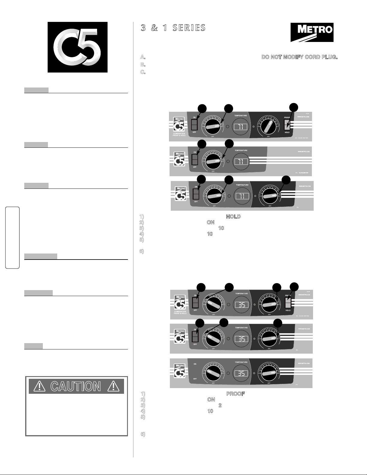
HOLDING INSTRUCTIONS
BASIC CABINET SETUP
CAUTION
A.
Refer to DATA PLATE for electrical requirements.
DO NOT MODIFY CORD PLUG.
B.
With POWER switch OFF, plug into 250 VAC grounded receptacle.
C.
Fill water pan to top with clean HOT tap water for Proofing or if moisture is desired
for Holding. Check water level every 3 hours (2 hours when Proofing) and refill with
clean HOT tap water as necessary. Water pan does not have to be filled for Holding.
Proofing requires water pan to be filled.
1)
Set Combination Module switch to
HOLD
2)
Set POWER switch to the ONposition.
3)
Set TEMPERATURE control to 10.
4)
Set MOISTURE control to 10(or desired level) on Moisture Module Only.
5)
Pre-heat cabinet until desired temperature is reached (typical heat-up time from
72˚(22˚C) ambient to 160˚(71˚C) is approximately 45 minutes).
6)
Re-set TEMPERATURE control and adjust as necessary to reach desired
temperature (setting 6-8 is typical for 150˚(66˚C) to 160˚ (71˚C)). Power indicator
light will turn on and off as the heat thermostat cycles.
1)
Set Combination Module switch to
PROOF
2)
Set POWER switch to the ONposition.
3)
Set TEMPERATURE control to 2.
4)
Set MOISTURE control to 10.
5)
Pre-heat cabinet until desired temperature and humidity is reached (typical
heat-up time from 72˚(22˚C) ambient to 95˚(35˚C) and 95% relative humidity is
approximately 30 minutes).
6)
Adjust settings as necessary to reach desired temperature and humidity levels.
Power indicator lights will turn on and off as the heat and moisture thermostats cycle.
3 & 1 S E R I E S
O P E R AT I N G IN S T R U C T I O N S
Breads
Biscuit, Buttermilk Mini 175˚ (79˚C)
Croissants, Sliced 155˚ (68˚C)
French Toast, Thin Slice 175˚ (79˚C)
Waffles, Original 175˚ (79˚C)
Pancakes 175˚ (79˚C)
Pizza 175˚ (79˚C)
Rolls 175˚ (79˚C)
Dough (Proofing) 90-100˚ (32-38˚C)
Meats
Prime Rib 175˚ (79˚C)
Hamburgers 180˚ (82˚C)
Hot Dogs 170˚ (77˚C)
Roast Beef 175˚ (79˚C)
Roast Pork 175˚ (79˚C)
Ribs (Pork Spareribs) 175˚ (79˚C)
Poultry
Chicken, Boneless, Skinless 175˚ (79˚C)
Chicken, Thigh, Baked, Fried 175˚ (79˚C)
Chicken, Full Breast 175˚ (79˚C)
Chicken, Drum, Baked, Fried 175˚ (79˚C)
Chicken, Leg 175˚ (79˚C)
Chicken, Fried Full Breast 175˚ (79˚C)
Chicken, Fried Thigh 175˚ (79˚C)
Chicken, Fried Drum 175˚ (79˚C)
Chicken, Fried Boneless Skinless 175˚ (79˚C)
Chicken, Whole Roasted 170˚ (77˚C)
Turkey 175˚ (79˚C)
Vegetables
Broccoli, Spears 175˚ (79˚C)
Carrots, Sliced, Crinkled 175˚ (79˚C)
Cauliflower, Clusters IQF 175˚ (79˚C)
Corn on the Cob 180˚ (82˚C)
Mixed Vegetables 175˚ (79˚C)
Fry, Regular 3/8" 195˚ (91˚C)
Potatoes, Mashed 175˚ (79˚C)
Potatoes, Baked 180˚ (82˚C)
Potatoes, Scalloped 175˚ (79˚C)
Starches
Pasta, Elbow Macaroni 180˚ (82˚C)
Rice 180˚ (82˚C)
Lasagna, Meat Sauce & Cheese 185˚ (85˚C)
Beans 175˚ (79˚C)
Fish
Fish, Baked (Cod Loin) IQF 170˚ (77˚C)
Fish, Batter Dipped 175˚ (79˚C)
Developed in conjunction with the Center for Food Innovation (CFI),
Penn State University
F O O D S E T T I N G S G U I D E
®
2
3
1
2
3
2
3
1
4
4
2
3
• WATER PAN MUST BE IN PLACE DURING MODULE OPERATION.
• UNPLUG CABINET FROM WALL AND ALLOW CABINET (AND
WATER) TO COOL BEFORE CLEANING OR SERVICING.
• DO NOT SPRAY OR POUR WATER ON THE MODULE WHEN
CLEANING AND DO NOT IMMERSE THE MODULE IN WATER.
WIPE WITH A DAMP CLOTH AND DRY WITH A TOWEL.
• KEEP CABINET AND MODULE CLEAN. ACCUMULATION OF
GREASE AND OTHER DRIPPINGS MAY IGNITE.
Moi stu re
Hol din g
Mod ule
SeeData Plate for
ElectricalSpecifications
MOISTURE
C5-PM-0001000
C05-963
MOISTURE
HOLDING
PROOFING INSTRUCTIONS
2
3
4
Moi stu re
Hol din g
Mod ule
SeeData Plate for
ElectricalSpecifications
MOISTURE
220-240 VOLT
Page 3
TABLE OF CONTENTS
SECTION PAGE
I. Basic Operating Guidelines ......Inside Front Cover
II. Safety Information .............................................. 1
III. Identifying Your Cabinet .................................... 2
IV. Installation & Set-up ........................................... 3
V. Product Features ............................................... 7
VI. Operating Instructions ....................................... 8
VII. Care & Maintenance ..........................................10
VIII. Basic Troubleshooting .......................................11
IX. Service & Replacement Parts ............................13
X. Warranty ..................................................24, 25-26
SAFETY INFORMATION
WARNING: Follow all food safety guidelines. Pre-heat the cabinet to the desired temperature before placing
cooked, hot food into the cabinet. This is not a re-thermalizing cabinet. Food must be at the
appropriate temperature before being placed into this cabinet. Use a food probe to check internal
food temperature — the cabinet temperature is not necessarily the internal food temperature.
WARNING: Only factory approved service agents should attempt to service, repair or replace electrical
components, wiring or power cord.
WARNING: Unplug the cabinet before cleaning or servicing. Do not wash the cabinet with a water jet or high
pressure water.
WARNING: This cabinet is for hot food holding applications only.
CAUTION: Do not spray or pour water into the module. To clean the cabinet, wipe with a damp cloth and dry with
a towel. Use only cleaning agents approved for aluminum.
CAUTION: Water dripping onto the floor from open doors can be a slip hazard.
220-240 volt
1
Page 4
IDENTIFYING YOUR CABINET
CABINET SIZE (HEIGHT)
9 = FULL
7 = 3/4
5 = 1/2
CABINET SIZE (HEIGHT)
9 = FULL
7 = 3/4
5 = 1/2
For future reference, record the cabinet model number &
manufactured date found on the date plate located at rear
of cabinet. Also record the module serial number located
inside the cabinet on module top right-hand corner.
Model number:
Cabinet manufactured date:
Module serial number:
Module manufactured date:
Fill out and return the warranty card located at
the back of this manual.
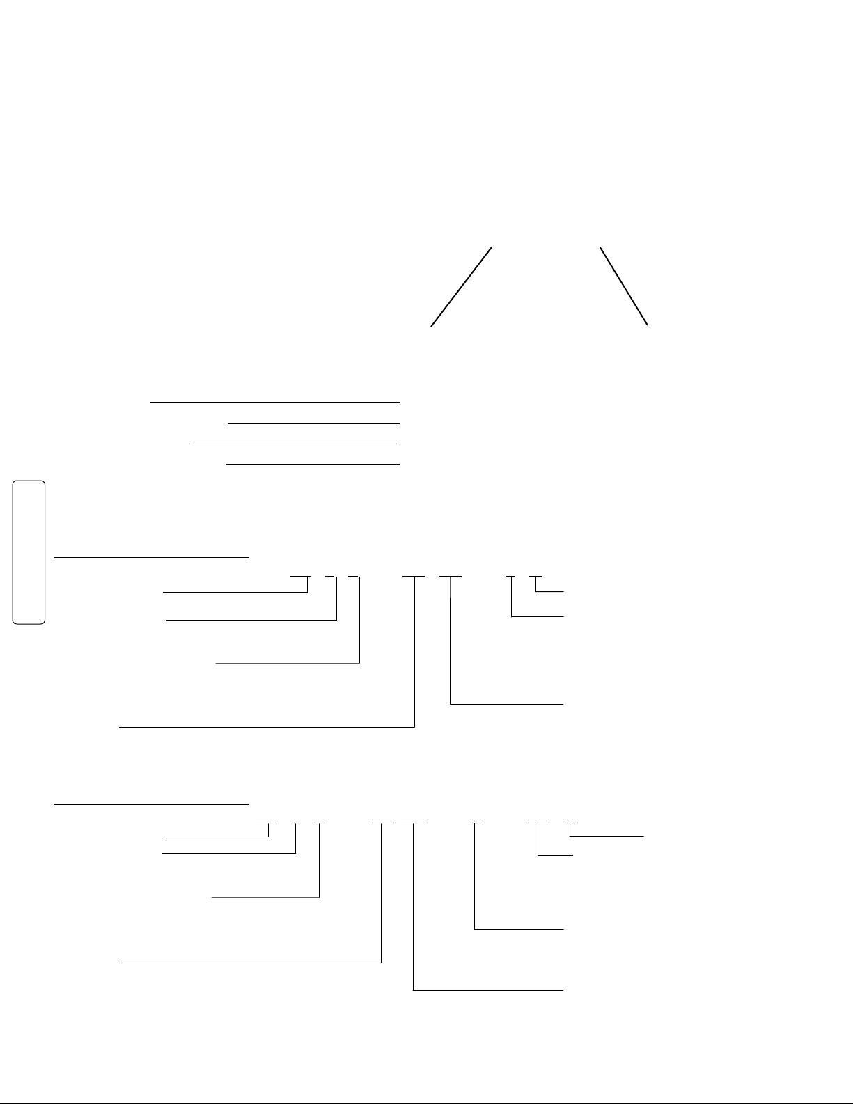
PART NUMBERING
C5 1 SERIES CABINET
CABINET NAME
220-240 volt
CABINET TYPE
1 = UN-INSULATED
MODULE
CX = C5-CX2000, COMBO, 2000 W.
HX = C5-HX2000, HOLDING, 2000 W.
PX = C5-PX1500, PROOFER, 1440 W.
C5 3 SERIES CABINET
CABINET NAME
CABINET TYPE
3 = INSULATED
MODULE
CX = C5-CM2000X, COMBO, 1681-1990 W.
HX = C5-HM2000X, HOLDING, 1681-1990 W.
PX = C5-PM1500X, PROOFER, 1210-1440 W.
MX = C5-MM2000X, MOISTURE HOLDING, 1681-1990 W.
C5 1 9 — HX FC — 4 A
A = ACCESSORIES
SLIDES
L = FIXED, LIP LOAD
U = ADJUSTABLE, UNIVERSAL
4 = FIXED WIRE
DOOR
FC = FULL CLEAR
C5 3 9 — HX DS — U — BU A
A = ACCESSORIES
PANEL COLOR
BG = BEIGE BLANK = RED
BU = BLUE SG = SAGE
GY = GRAY GREEN
OR = ORANGE YL = YELLOW
SLIDES
L = FIXED, LIP LOAD
U = ADJUSTABLE, UNIVERSAL
4 = FIXED WIRE
DOOR(S)
FS = FULL SOLID
DS = DUTCH SOLID
FC = FULL CLEAR
DC = DUTCH CLEAR
2
Page 5

INSTALLATION AND SET-UP
1. Check for Shipping Damage: Check the packaging and cabinet for shipping damage after unloading the unit,
and after removing all the packaging.
2. The receiver of this product is responsible for filing freight damage claims. This equipment must be opened
immediately for inspection. All visible damage must be reported to the freight company within 48 hours and must
be noted on freight bill at the time of delivery.
3. Concealed damage is your responsibility — you must advise the carrier of any loss or damage within 15 days
after receipt of the cabinet. If there is damage, retain the original packaging for inspectors.
4. After unpacking the cabinet, remove all tape and packing material from the inside as well as outside of the unit.
5. Any protective covers (plastic or paper sheet) on the sheet metal or clear door, if applicable, must also be
removed before turning the cabinet on.
WARNING: Only factory approved service agents should attempt to service, repair or replace electrical
components, wiring or the power cord.
6. Refer to the data plate at the lower rear of the cabinet for the electrical specifications. With the power switch off,
plug the cord into a 250 VAC, 15 amp, grounded receptacle.
250 VAC 15 Amp Outlet
220-240 volt
All Modules
CAUTION: A 3 Series cabinet (polymer Insulation Armour panels on the sides, top and rear) must not be placed
next to char broilers. Allow 18" (46cm) between the Insulation Armour and any cooking equipment. Do
not allow hot kitchen equipment whose surfaces exceed 200°F (90°C) to touch the panels.
WARNING: Do not allow combustible materials to be stored or accumulate on, under or next to the cabinet.
Do not block any ventilation louvers or slots.
NOTE: Temperature is displayed in °C.
3
Page 6
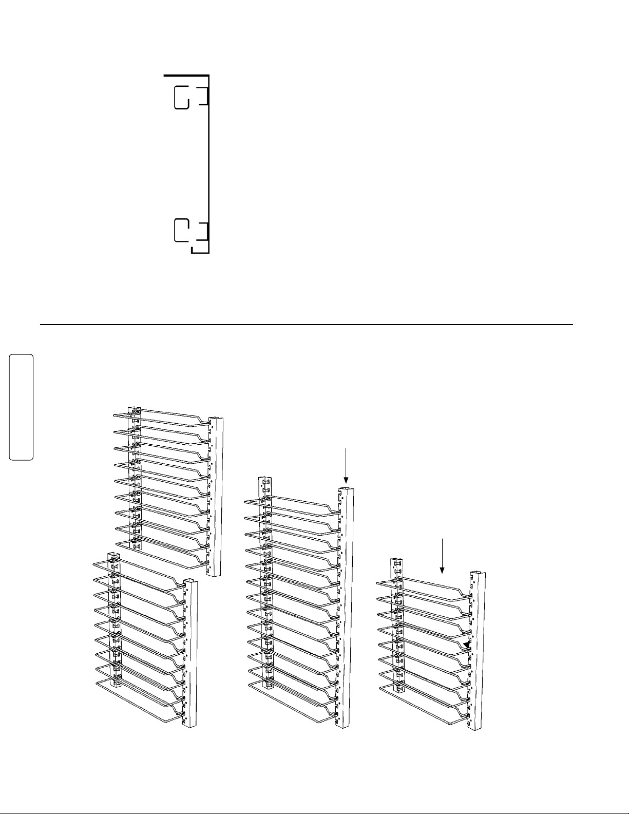
INSTALLATION AND SET-UP (continued)
SLIDE INSTALLATION
The rack uprights
have been installed
at the factory. If
removed for cleaning,
reinstall by hanging
them on the rack
brackets on the side
walls of the cabinet.
TOP VIEW
3" PAN CAPACITY UNIVERSAL SLIDES
(ITEM #17 ON REPLACEMENT PARTS LIST, PAGE 13)
INDIVIDUAL UNIVERSAL UPRIGHTS
(ITEM #29 ON REPLACEMENT
PARTS LIST, PAGE 13)
220-240 volt
UNIVERSAL WIRE SLIDE
(ITEM #19 ON REPLACEMENT
PARTS LIST, PAGE 13)
FULL HEIGHT
3/4 HEIGHT
4
1/2 HEIGHT
Page 7

INSTALLATION AND SET-UP (continued)
CORRECT ORIENTATION OF LIP LOADED SLIDES
(ITEM #18 ON REPLACEMENT PARTS LIST, PAGE 13)
FULL HEIGHT
3/4 HEIGHT
1/2 HEIGHT
CORRECT ORIENTATION OF FIXED WIRE SLIDES
(ITEM #16 ON REPLACEMENT PARTS LIST, PAGE 13)
220-240 volt
FULL HEIGHT
3/4 HEIGHT
1/2 HEIGHT
5
Page 8

REVERSING THE DOORS
The door on your cabinet can be reversed to accommodate a right- or left-hand opening. The cabinet has been
shipped with the hinges mounted on the right-hand side. To reverse, follow the instructions listed below:
1. With the door in the closed position, remove the hinge pin by driving it out using a hammer and a drive pin or
small diameter screwdriver.
2. Once the pins are removed grasp the door firmly and pull the latch lever, this will release the door. Set the door
aside being careful not to damage the gasket.
3. Remove the screws from the left side of the cabinet and set aside. Then remove the cabinet mounted part of the
hinge and remount to the left side of the cabinet. Put the screws removed from the left side of the cabinet into the
remaining holes on the right side of the cabinet. Tighten all screws before proceeding.
4. Relocate the latch plate(s) from the left side to the right by removing the two mounting screws. Tighten all screws
before proceeding.
5. Rotate the door 180 degrees and align the door mounted hinge part with the cabinet mounted hinge part and tap
the hinge pin into place so the top of the pin is flush with top of the cabinet mounted hinge part. Invert the door
latch by removing the black plastic screw covers and remove the screws holding the latch in place.
220-240 volt
6
Page 9

PRODUCT FEATURES
• The module has been placed at
the base of the cabinet for easy
accessibility and efficient operation.
• Clearly-marked control panel for easy
viewing allows climate adjustments
without opening the door.
• Removable water pan.
• Cabinet designed with drip trough and
catch pan to contain condensation
drippage.
• Field reversible, gasketed door.
• Easy pull adjustable magnetic door
latch.
• Cord keeper at rear of cabinet.
• All components — door, module, slide
racks — are removable to permit
thorough, obstruction-free cleaning.
220-240 volt
7
Page 10
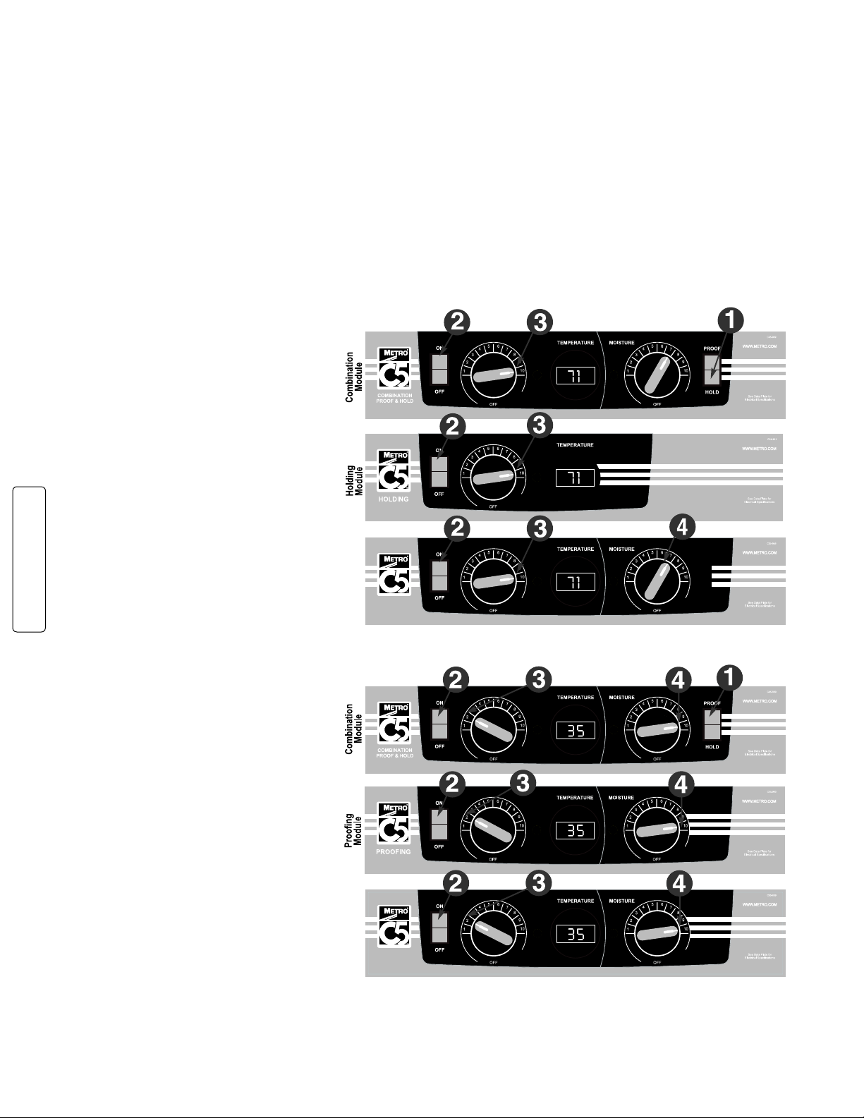
OPERATING INSTRUCTIONS
Moisture Holding
Module
MOISTURE
HOLDING
MOISTURE
HOLDING
Moisture Holding
Module
Power-Up & Pre-Heat
Your C5 1 SerieS or 3 SerieS Cabinet maY be equipped with Several different moduleS:
C5 1 SERIES C5 3 SERIES
COMBINATION PROOF & HOLD MODULE COMBINATION PROOF & HOLD MODULE
HOLDING MODULE HOLDING MODULE
PROOFING MODULE PROOFING MODULE
MOISTURE HOLDING MODULE
A. Refer to the DATA PLATE for electrical requirements. DO NOT MODIFY CORD PLUG.
B. With POWER switch OFF, plug into a 250 VAC grounded receptacle.
1
C. Fill the water pan to
Check water level every 3 hours (2 hours when Proofing) and refill with clean HOT tap water as necessary. Water
pan does not have to be filled for Holding. Proofing and Moisture Holding Module require water pan to be filled if
moisture control is turned on.
HOLDING INSTRUCTIONS
1) Set Combination Module switch to
HOLD.
2) Set POWER switch to the ON position.
3) Set TEMPERATURE control to 10.
4) Set MOISTURE control to 10.
5) Pre-heat cabinet until desired
temperature is reached (typical heat-up
time from 72°F (22°C) ambient to 160°F
(71°C) is approximately 45 minutes).
6) Re-set TEMPERATURE control and
adjust as necessary to reach the
desired temperature (setting 6-8 typical
for 150°F (66°C) to 160°F (71°C)).
Power indicator light will turn on and off
as the heat thermostat cycles.
7) Adjust MOISTURE control to desired
level (10 being highest level, 1 lowest
level, OFF being no heat to the water).
The indicator lights will turn on and off as
220-240 volt
the heat and moisture thermostats cycle.
PROOFING INSTRUCTIONS
1) Set Combination Module switch
to PROOF.
2) Set POWER switch to the ON position.
3) Set TEMPERATURE control to 2.
4) Set MOISTURE control to 10.
5) Pre-heat cabinet until desired
temperature and humidity is reached
(typical heat-up time from 72°F (22°C)
ambient to 95°F (35°C) and 95% relative
humidity is approximately 30 minutes).
6) Adjust settings as necessary to reach
the desired temperature and humidity
levels. Power indicator lights will turn
on and off as the heat and moisture
thermostats cycle.
7) Adjust MOISTURE control to desired
level (10 being highest level, 1 lowest
level, OFF being no heat to the water).The
indicator lights will turn on and off as the
heat and moisture thermostats cycle.
When the power switch is on, the blower is
always energized, circulating air, and the
digital thermometer is always displaying the cabinet temperature. When the thermostat senses heat is required, the
appropriate indicator will light and the heater element will begin to produce heat.
/2" from the top with clean HOT tap water for Proofing or if moisture is desired for Holding.
8
Page 11
• At the end of the operating day, it is not necessary to disrupt the temperature setting to turn the cabinet off. By
switching the power switch off, the cabinet is no longer operating. When resuming operations, switch the power on
and the cabinet will attain the previous temperature and moisture levels.
CAUTION: The water pan must be in place during module operation.
CAUTION: Water inside this cabinet’s pan is hot during use! Turn off and allow the water to cool before emptying
the pan.
NOTE: The POWER switch is not a foot switch. Using it as a foot switch can damage the switch and make the
WARNING: Follow all food safety guidelines. Preheat the cabinet to the desired temperature before putting
• Your C5 1 Series or 3 Series cabinet is capable of creating some humid air. As you operate the cabinet and
CAUTION: Water dripping onto the floor from open doors can be a slip hazard.
NOTE: When turning the cabinet off at the end of the workday, it is recommended to leave the door(s) open to
cabinet inoperable.
cooked, hot food into the cabinet. This is not a rethermalization cabinet. Food must be at the
appropriate temperature before being placed into this cabinet.
open and close the door(s), condensation may form on the inside surfaces of the cabinet. Some dripping of
water may occur to the outside of the cabinet particularly at the door seals. Water may also drip off opened
doors onto the floor.
prevent heat and condensation build up within the cabinet.
FOOD HOLDING GUIDELINES
A. C5-CM2000/C5-HM2000
A. C5-CM1500/C5-HM1500
Recommended Food Holding Guidelines
Food Product Covered/Uncovered Temperature Setting*
Baked Fish Uncovered 175°F (79°C)
Baked Potatoes Uncovered 180°F (82°C)
Biscuit Uncovered 180°F (82°C)
Broccoli Covered 170-175°F (77-79°C)
Chicken Nuggets Uncovered 175°F (79°C)
Corn on the Cob Covered 170-175°F (77-79°C)
Croissants Uncovered 175°F (79°C)
Egg Patties Covered 180°F (82°C)
French Fries** Uncovered 185°F (85°C)
Fried Chicken Uncovered 180-185°F (82-85°C)
Fried Fish Uncovered 180°F (82°C)
Hamburgers Covered 180°F (82°C)
Lasagna Covered 185° F (85°C)
Mashed Potatoes Covered 175°F (79°C)
Mixed Veggies Covered 170-175°F (77-79°C)
Pancakes Covered 175°F (79°C)
Pasta Covered 180°F (82°C)
Peas Covered 170-175°F (77-79°C)
Pizza Uncovered 175-180°F (79-82°C)
Roast Beef Uncovered 170-180°F (77-82°C)
Roast Pork Uncovered 170-180°F (77-82°C)
Scalloped Potatoes Covered 175°F (79°C)
Strip Steak Uncovered 160-170°F (71-77°C)
Turkey Uncovered 170-180°F (77-82°C)
Waffles Covered 175°F (79°C)
Whole Chicken Uncovered 170-180°F (77-82°C)
*Temperatures are guidelines only, based on opening cabinet doors every 15 minutes.
**Lightly salted for best quality.
Developed by Penn State University School of Hotel, Restaurant, and Recreation Management
220-240 volt
9
Page 12

CARE AND MAINTENANCE
Cleaning The Cabinet
WARNING: Unplug the cabinet before cleaning or servicing. Do not wash the cabinet with a water jet or high-pressure
water.
WARNING: Allow the unit to cool before cleaning, as the interior of the cabinet may be hot enough to burn. Also, allow the
water in the pan to cool before removal.
CAUTION: Do not spray or pour water into the control module. To clean the cabinet and module, wipe with a damp cloth
and dry with a towel. Use only cleaning agents approved for aluminum.
CAUTION: Do not use strong alkalis as it may discolor aluminum.
• Use cleaners in the proper concentrations. Follow the manufacturer’s directions for the cleaning product used. After using
any cleaning products, thoroughly rinse all surfaces to remove all residue.
• Use a damp cloth or sponge. Mild soap suitable for aluminum is acceptable. Dry with a clean towel. Wipe up spills as
soon as possible and regularly clean the cabinet to avoid staining and difficult to clean conditions.
• If a control knob needs to be removed for cleaning, remove the knob, clean the knob recess and knob, and replace the
knob.
1. Make sure the power cord is NOT hooked onto the cord keeper. Open the door(s). If there is water in the pan, remove
and empty. Remove the module from the cabinet by lifting up the front enough to clear its detent, and then pull the
module away from the cabinet. The power cord slips through the clearance hole at the rear of the cabinet.
2. Remove the slide racks.
3. After cleaning, replace all components. Make sure the slide racks are seated in the hangers correctly.
4. Push the power cord through the plastic snap bushing in the rear of the cabinet and install the module.
CLEANING INSTRUCTIONS for CLEAR, POLYCARBONATE DOORS (if applicable):
The protective masking on the polycarbonate door may be removed by simply peeling it from the door, starting at a
top corner and working downward. For regular cleaning, a soft cotton flannel cloth and a cleaner recommended by its
manufacturer for use on polycarbonate plastics is suggested. Do not use synthetic cloths or cleaners not intended for
polycarbonate plastics as these will scratch and dull the polycarbonate door panel. Additional hints for keeping the door
panel clean and clear:
a. Isopropyl (rubbing) alcohol, used as a cleaner, will aid in removing grease smudges and fingerprints.
b. A small amount of liquid dish detergent in a bucket of water will help remove heavier dirt and will help make the clear
panel antistatic and therefore less likely to attract dust.
c. A paste-wax recommended for polycarbonate plastics and approved for food service equipment will hide small
220-240 volt
scratches and return the luster and clarity to the clear door panel as well as reduce the electrostatic attraction of dust.
CLEANING INSTRUCTIONS for 3 SERIES INSULATION ARMOUR PANELS ON SIDES,
TOP AND BACk:
Use soft cloth, mild soap water solution to clean lightly-soiled surfaces. Then wipe dry with a clean, soft cloth. For
heavily-soiled areas, use a soft brush and solvent or emulsion-based cleaner. Always insure the cleaner is recommended
for use on plastics and follow any special instructions from the manufacturer.
10
Page 13
BASIC TROUBLESHOOTING
Module operation basics:
When the power switch is on, the blower is always energized, circulating air, and the digital thermometer is always displaying
the cabinet temperature. A thermostat controls whether an element will be energized depending on the thermostat setting
and the air temperature it is sensing. The control knob is used to change the thermostat setting. When a thermostat senses
the temperature has gone below its set point, the thermostat contacts close, the appropriate indicator will light and the heater
element will begin to produce heat. When the thermostat senses the temperature has reached its set point, the contacts open,
the indicator light will go out and the heater element will stop producing heat.
Holding Module: The holding module has one heating element. It is in the air duct and heats up the air as it is circulated in
the cabinet. The thermostat senses the return air temperature and will energize the air duct element as required to heat up
the cabinet air. Some moisture can be introduced by filling the water pan with warm water and allowing the warm air to pick
up the water vapor as the blower circulates the air. There is no heating element to heat the water.
Moisture Holding and Proofing Module: There are two heating elements in these modules. One is in the air duct to heat
the air, and one is under the water pan to heat the water and introduce moisture into the cabinet. One thermostat senses
the return air temperature and will energize the air duct element as required to heat up the cabinet air. The other thermostat
senses the air temperature around the water pan. It will energize the water pan element to heat the water and release moisture
into the cabinet.
Combination Proof and Hold Module: A combination proof and hold module has a mode switch, which allows the module to
act as either a holding module or a proofing module. Therefore, it has all the elements of both a holding module and a proofing
module. When the mode selector switch is set to HOLD, only the larger wattage air element is used. The water pan element
is not used. When the mode selector switch is set to PROOF, the lower wattage air element and the water pan element are
used but independently controlled by individual thermostats. See the appropriate paragraph above for more detail on how
the Combination Proof and Hold Module operates in either holding or proofing mode.
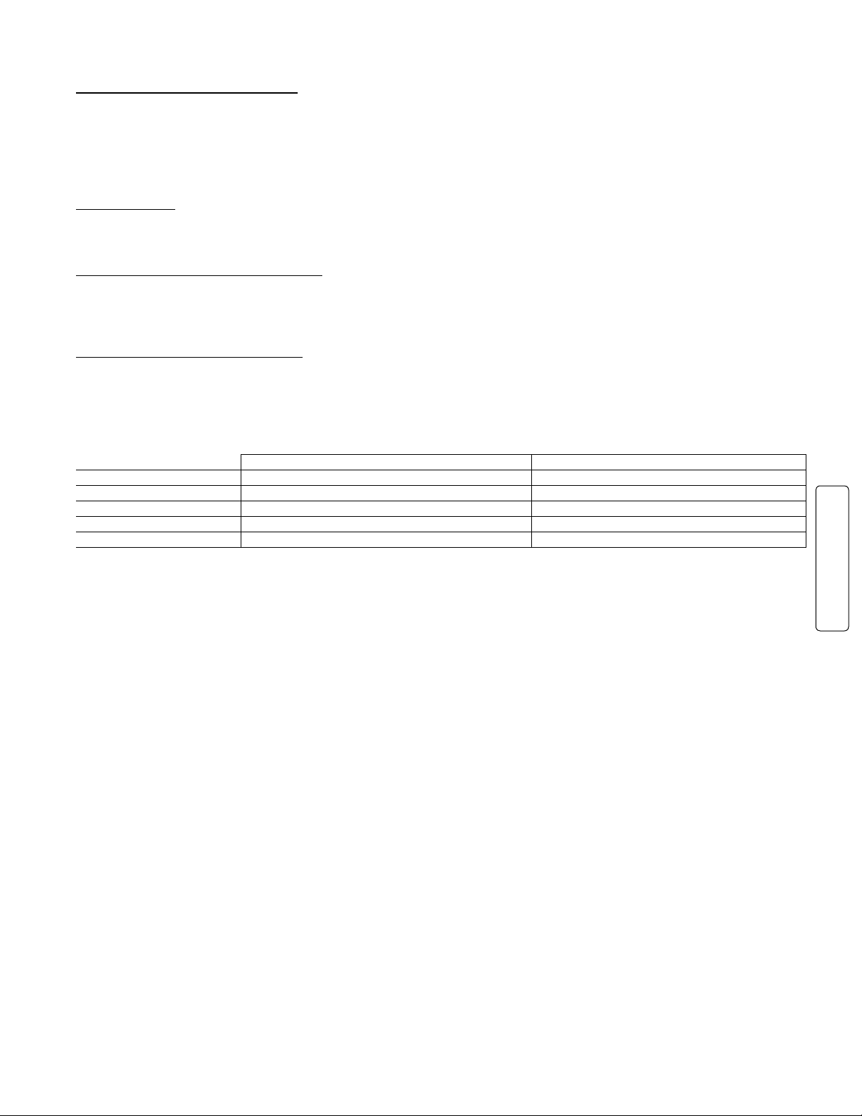
Element wattages are shown in the chart below:
220-240V, 1681-2000W cabinet 220-240V, 1210-1440W cabinet
Air Duct element Water Pan element Air Duct element Water Pan element
Combination module 1950 watt and 675 watt 675 watt
Holding module 1950 watt none
Proofing module 675 watt 675 watt
Moisture Holding module 1360 watt 590 watt
Note: The amp draw for the blower and digital thermometer is approximately 0.4 to 0.45 amps. Add the appropriate amp
draw per the element chart above when an element(s) is energized.
WARNING: Only factory approved service agents should attempt to service, repair or replace electrical components,
wiring or power cord.
1. Controls do not work (digital thermometer and indicator light(s) not lit):
a. Check that the cabinet is plugged in.
b. Check that the outlet has power. Is electrical service fuse blown or circuit breaker tripped?
c. Check that the power switch is in the “On” position.
d. Check the cabinet wiring from the power cord to the power switch and to the terminal block.
e. Power switch could be bad.
2. Temperature too hot:
a. Temperature set point is too high. Turn control knob down to a lower setting. Wait several minutes and see if
the displayed temperature decreases.
b. Thermostat may have failed with contacts closed. Check thermostat.
c. If displayed temperature exceeds 220°F (104°C):
i. Blower wiring is faulty or disconnected.
ii. Blower needs replacing. Check blower.
iii. The thermostat or blower may have failed and the thermal overload device is controlling the temperature.
Stop using the cabinet immediately and contact a factory approved service agent.
3. Temperature too low:
a. The cabinet may still be in pre-heat or recovering from a door being opened.
b. Temperature set point is too low. Turn temperature control knob to a higher setting. Wait several minutes and
see if the displayed temperature increases.
c. A door is not closed or sealing properly.
d. Blower is not circulating air:
i. Blower wiring is faulty or disconnected.
ii. Blower needs replacing.
4. Indicator light is not working:
It is rare that an indicator light will be defective but it is possible. The thermostat contacts may not be closing
and therefore the heater element is not being energized. Check the thermostat and pilot light and their
respective wiring.
220-240 volt
11
Page 14

BASIC TROUBLESHOOTING
5. No heat generated:
a. If the heat indicator light is on, but the cabinet does not draw the appropriate amperage per the chart on
page 11:
i. Air heater element may be faulty.
ii. The wiring to the air heater element may be faulty or disconnected.
iii. The thermostat may be faulty.
b. If the heat indicator light is not on, the thermostat contacts may not be closing and therefore the heater element
is not being energized. It is rare that the indicator light will be defective but it is possible. Check the thermostat
and pilot light and their respective wiring.
6. Moisture level is too low:
a. If the heat indicator light is on, and the cabinet draws the appropriate amperage per the chart on page 11:
i. Check that the water pan has water.
ii. A door is not closed or sealing properly.
iii. Moisture set point is too low. Turn moisture control knob to a higher setting.
b. If the heat indicator light is on, but the cabinet does not draw the appropriate amperage per the chart on
page 11:
i. Air heater element may be faulty.
ii. The wiring to the air heater element may be faulty or disconnected.
iii. The thermostat may be faulty.
c. If the heat indicator light is not on, the thermostat contacts may not be closing and therefore the heater element
is not being energized. It is rare that the indicator light will be defective but it is possible. Check the thermostat
and pilot light and their respective wiring.
7. Cabinet trips GFCI (ground fault circuit interrupter):
A GFCI receptacle protects against “ground faults” whenever an electrical product is plugged into the GFCI outlet by
constantly monitoring the electricity for any loss of current. If the current flowing out of the receptacle differs by a small
amount from that returning, the GFCI quickly switches off power to that circuit. The GFCI interrupts power extremely
fast to minimize the possibility of an electric shock.
a. The heater element may absorb some moisture into its casing and insulation during shipment or during long
periods of not being used (such as during the summer in a closed school kitchen). Plug the cabinet (without
water in the water pan) into a non-GFCI outlet, set the temperature to “10” and let it run for 30-60 minutes to dry
out any moisture the element may have absorbed. (If it trips the standard circuit breaker call factory approved
service agent.) After drying the element, plug the cabinet into the GFCI outlet; the cabinet should run without
tripping the GFCI.
b. If the cabinet still trips the GFCI, call a factory approved service agent.
(continued)
220-240 volt
12
Page 15

SERVICE and REPLACEMENT PARTS
C5 1 & 3 SERIES EXPORT CABINETS
Item # Replacement Part No. Description
CABINET BODY
1 RPC5-19-FCDR COMPLETE FULL HEIGHT CLEAR DOOR
RPC5-17-FCDR COMPLETE 3/4 HEIGHT CLEAR DOOR
RPC5-15-FCDR COMPLETE 1/2 HEIGHT CLEAR DOOR
RPC5-39-TCDR COMPLETE TOP CLEAR DUTCH DOOR
RPC5-39-BCDR COMPLETE BOT. CLEAR DUTCH DOOR
2 RPC5-39-FSDR COMPLETE FULL HEIGHT SOLID DOOR
RPC5-37-FSDR COMPLETE 3/4 HEIGHT SOLID DOOR
RPC5-35-FSDR COMPLETE 1/2 HEIGHT SOLID DOOR
RPC5-39-TSDR COMPLETE TOP SOLID DUTCH DOOR
RPC5-39-BSDR COMPLETE BOT. SOLID DUTCH DOOR
3 RPC14-119 DOOR HINGE ( QTY. 1)
4 RPC14-118 DOOR LATCH, OFFSET HANDLE
RPC14-118A DOOR LATCH, FLUSH HANDLE
5 RPC06-910A FULL HEIGHT CLEAR DOOR GASKET
RPC06-910B
RPC06-910C
3
/4 HEIGHT CLEAR DOOR GASKET
1
/2 HEIGHT CLEAR DOOR GASKET
RPC06-910D CLEAR DUTCH DOOR GASKET
6 RPC06-916A FULL HEIGHT SOLID DOOR GASKET
RPC06-916B
RPC06-916C
3
/4 HEIGHT SOLID DOOR GASKET
1
/2 HEIGHT SOLID DOOR GASKET
RPC06-916D SOLID DUTCH DOOR GASKET
7 B5DNB 5" BRAKE CASTER
RPQC02-248 6" BRAKE CASTER
8 B5DN 5" SWIVEL CASTER
B5DNR 5" RIGID CASTER
RPQC02-247 6" SWIVEL CASTER
9 RPC5-SSLEG-1 STATIONARY EQUIPMENT LEG (QTY. 1)
10 RPC5-DPTRH POLY DRIP THROUGH & SCREWS
11 RPC06-179 DRIP PAN
12 RPC5-RHANDLE REAR HANDLE & SCREWS
(USED ONLY ON 1 SERIES)
13 RPC5-TRVL TRAVEL LATCH
14 RPC5-1-BMPR 1 SERIES CORNER BUMPERS
(2 FRONT, 2 REAR & SCREWS )
15 RPC13-106 POWER CORD BUSHING
16* C5-13-FW-9 FULL HEIGHT FIXED WIRE SLIDES
C5-13-FW-7
C5-13-FW-5
17* C5-13-U-9 FULL HEIGHT UNIV SLIDES & UPRIGHTS
C5-13-U-7
C5-13-U-5
18* C5-13-L-9 FULL HEIGHT LIP LOAD SLIDES
C5-13-L-7
C5-13-L5
3
/4 HEIGHT FIXED WIRE SLIDES
1
/2 HEIGHT FIXED WIRE SLIDES
3
/4 HEIGHT UNIV SLIDES & UPRIGHTS
1
/2 HEIGHT UNIV SLIDES & UPRIGHTS
3
/4 HEIGHT LIP LOAD SLIDES
1
/2 HEIGHT LIP LOAD SLIDES
19 C5-USLIDECPR CHROME UNIV WIRE SLIDES — 1 PAIR
C5-USLIDESPR SS UNIVERSAL WIRE SLIDES —1 PAIR
20 C5-SHELF ACCESSORY SHELF
(USED WITH UNIVERSAL UPRIGHTS)
Item # Replacement Part No. Description
OUTSIDE POLY PANELS ON C5 3 SERIES CABINETS
23 RPC3-TPNL-BG BEIGE TOP PANEL — INCLUDES SCREWS
RPC3-TPNL-BU BLUE TOP PANEL — INCLUDES SCREWS
RPC3-TPNL-GY GRAY TOP PANEL — INCLUDES SCREWS
RPC3-TPNL-RE RED TOP PANEL — INCLUDES SCREWS
24 RPC3-SD27-BG BEIGE 27" SIDE PANEL —
RPC3-SD27-BU BLUE 27" SIDE PANEL —
RPC3-SD27-GY GRAY 27" SIDE PANEL —
RPC3-SD27-RE RED 27" SIDE PANEL —
25 RPC3-SD21-BG BEIGE 21" SIDE PANEL —
RPC3-SD21-BU BLUE 21" SIDE PANEL —
RPC3-SD21-GY GRAY 21" SIDE PANEL —
RPC3-SD21-RE RED 21" SIDE PANEL —
26 RPC3-IA-BTPNL BOTTOM SIDE PANEL —
INCLUDES SCREWS
27 RPC3-IA-RTNR MIDDLE PANEL RETAINER —
INCLUDES SCREWS
28 RPC5-3-BASECLP BOTTOM PANEL CLAMP & SCREWS
29 RPC53-5URT* FULL & 1/2 HEIGHT UNIV UPRIGHTS
(QTY. 1)
*(Full height cabinet uses same uprights)
RPC53-7URT
30 RPC519-PKG FULL & 3/4 HEIGHT 1 AND 3 SERIES
CABINET RETURN PACKAGING
RPC515-PKG
CABINET RETURN PACKAGING
*See pages 4 and 5 for slide identification. All slides
sold in pairs. Universal slides include uprights.
INCLUDES SCREWS
INCLUDES SCREWS
INCLUDES SCREWS
INCLUDES SCREWS
INCLUDES SCREWS
INCLUDES SCREWS
INCLUDES SCREWS
INCLUDES SCREWS
3
/4 HEIGHT UNIV UPRIGHTS (QTY. 1)
1
/2 HEIGHT 1 AND 3 SERIES
220-240 volt
13
Page 16

SERVICE and REPLACEMENT PARTS (continued)
C5 1 & 3 SERIES EXPORT CABINET MODULES
MOISTURE
MODULE TYPE: COMBO HOLDING PROOFER HOLDING
ITEM# PART # DESCRIPTION QTY QTY QTY QTY
30 RPC13-127 POWER SWITCH (RED) 1 1 1 1
31 RPC13-128 SELECTOR SWITCH (WHITE) 1 1 N/A
32 RPC06-913 THERMOSTAT KNOB 2 1 2 2
33 RPC13-234 THERMOSTAT 2 1 2 2
34 RPC09-213 THERMOSTAT MOUNTING CUP 2 1 2 2
35 RPC13-246 AMBER INDICATOR LIGHT 2 1 2 2
36 RPC13-248 °C THERMOMETER & 220-240V TRANSFORMER 1 1 1 1
38 RPC11-191 BLOWER INTAKE COLLAR 1 1 1 1
39 RPHX20-2103 BLOWER, 220-240V, 50/60HZ 1 1 1 1
40 RPC13-243 HEAT ELEMENT, “M” SHAPED, 240V, 1950W 1 1 N/A
40A RPC13-292 HEAT ELEMENT, “M” SHAPED, 240V, 1360W 1
41 RPC13-242 HEAT ELEMENT, “U” SHAPED, 240V, 675W 2 2 N/A
42 RPC13-198 THERMAL CUT-OUT 1 1 1 1
43 RPC13-247 POWER CORD, 250VAC 15A, NEMA 6-15P 1 1 1
44 RPC13-083 STRAIN RELIEF BUSHING 1 1 1
45 RPC13-096 TERMINAL BLOCK 1 1 1 1
46 RPC07-055 GROMMET 1 1 1 2
47 RPC56-SCLP SENSOR & BULB CLAMP KIT 1 1 1 1
48 RPC11-185 SS WATER PAN 1 1 1 1
49 RPC06-206 STEM BUMPER, MODULE STOP 2 2 2 2
50 RPC13-291 HEAT ELEMENT, 240V, 590W 1
220-240 volt
REPLACEMENT MODULES
51 RPC5-CM2000X REPLACEMENT COMBO, 220-240V, 1681-1990W MODULE
52 RPC5-HM2000X REPLACEMENT HOLDING, 220-240V, 1681-1990W MODULE
53 RPC5-PM1500X REPLACEMENT PROOFING, 220-240V, 1210-1440W MODULE
54 RPC5-MM2000X REPLACEMENT MOISTURE HOLDING, 220-240V, 1681-1990W MODULE
14
Page 17
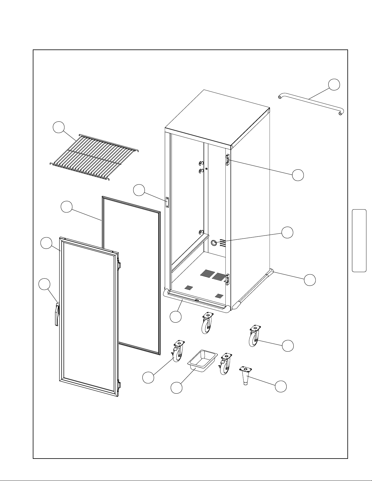
SERVICE and REPLACEMENT PARTS (continued)
C5 1 Series Cabinet Replacement Parts Diagram
20
3
13
12
5
15
1
220-240 volt
4
10
8
7
11
9
14
FOR RETURN CABINET PACKAGING
SEE ITEM #30, PAGE 13.
*See pages 4 and 5 for slide identification. All slides sold in pairs.
*See pages 4 and 5 for slide identification. All slides sold in pairs.
15
Page 18
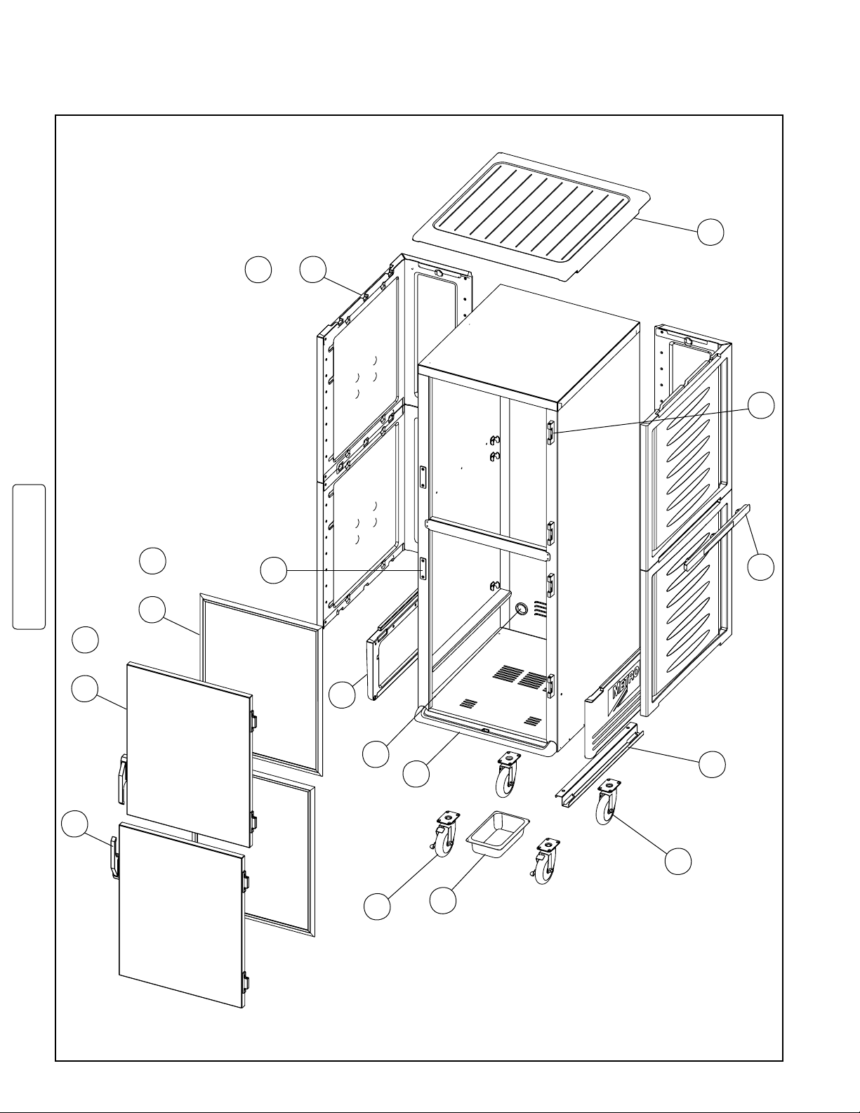
SERVICE and REPLACEMENT PARTS (continued)
C5 3 Series Cabinet Replacement Parts Diagram
NOTE: Replacement panels
are ordered by color.
See chart on page 13.
OR
24
25
23
3
220-240 volt
5
OR
13
27
6
1
OR
2
26
15
10
28
4
8
7
11
FOR RETURN CABINET PACKAGING
SEE ITEM #30, PAGE 13.
*See pages 4 and 5 for slide identification. All slides sold in pairs.
16
Page 19
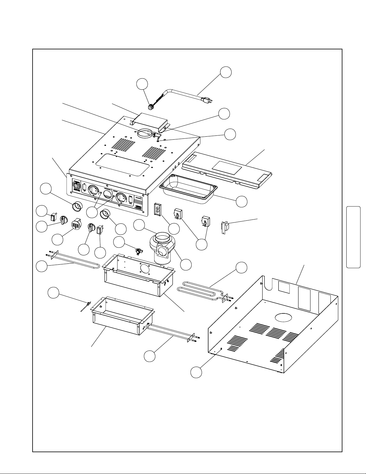
SERVICE and REPLACEMENT PARTS (continued)
C5-CM2000X EXPORT COMBO MODULE
43
HEAT THERMOSTAT
BULB &
THERMOMETER
SENSOR
MODULE
CHASSIS
CONTROL
PANEL
34
30
32
36
32
41
INTAKE
COVER
35
31
34
42
38
44
45
39
33
47
46
48
40
AIR DISCHARGE
COVER
TRANSFORMER
SUPPLIED WITH
THERMOMETER
ITEM #36
BOTTOM COVER
220-240 volt
47
MOISTURE
THERMOSTAT
BULB
WATER PAN
ENCLOSURE
41
AIR DUCT
49
FOR REPLACEMENT C5-CM2000X MODULE, ORDER ITEM #51 ON PAGE 14
17
Page 20
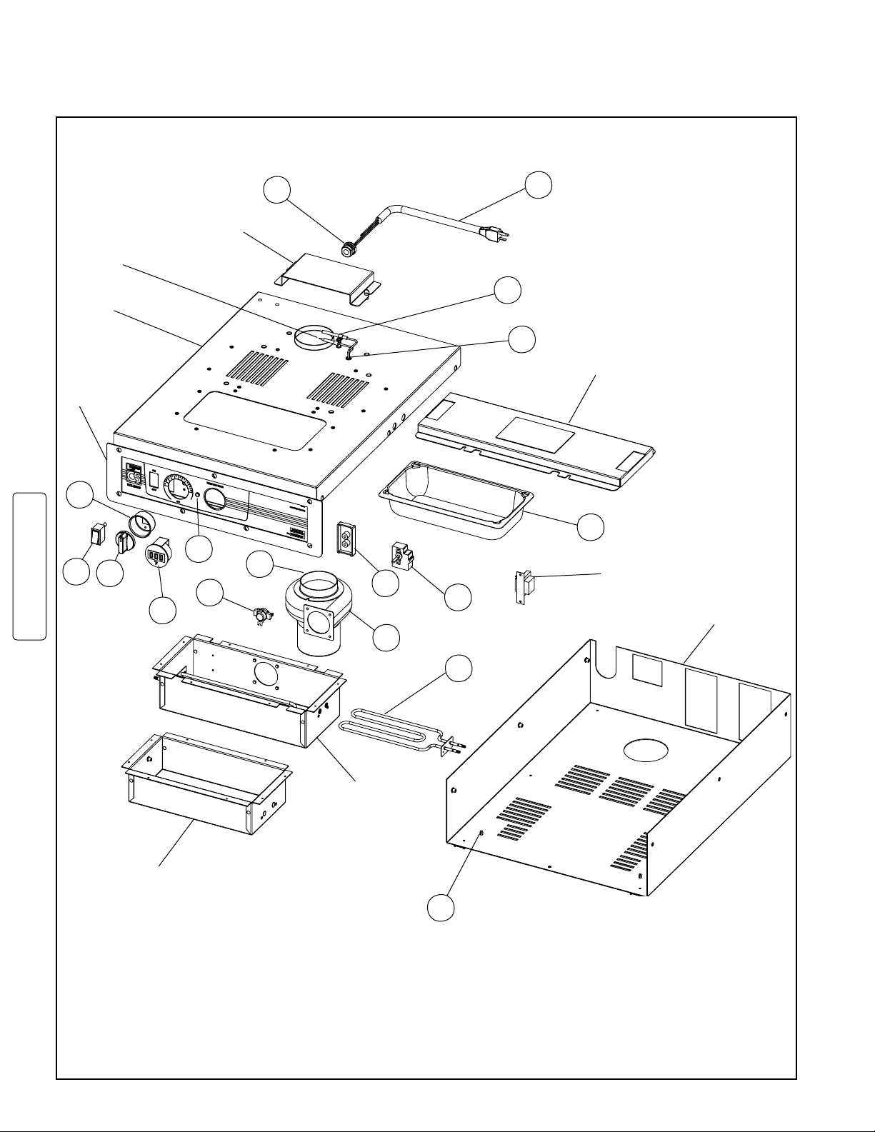
SERVICE and REPLACEMENT PARTS (continued)
C5-HM2000X EXPORT HOLDING MODULE
HEAT THERMOSTAT
BULB &
THERMOMETER
SENSOR
MODULE
CHASSIS
CONTROL
PANEL
34
30
32
220-240 volt
36
AIR INTAKE
COVER
35
42
38
44
45
39
33
47
46
43
AIR DISCHARGE
COVER
48
TRANSFORMER
SUPPLIED WITH
THERMOMETER
ITEM #36
BOTTOM COVER
40
AIR DUCT
WATER PAN
ENCLOSURE
49
FOR REPLACEMENT C5-HM2000X MODULE, ORDER ITEM #52 ON PAGE 14
18
Page 21
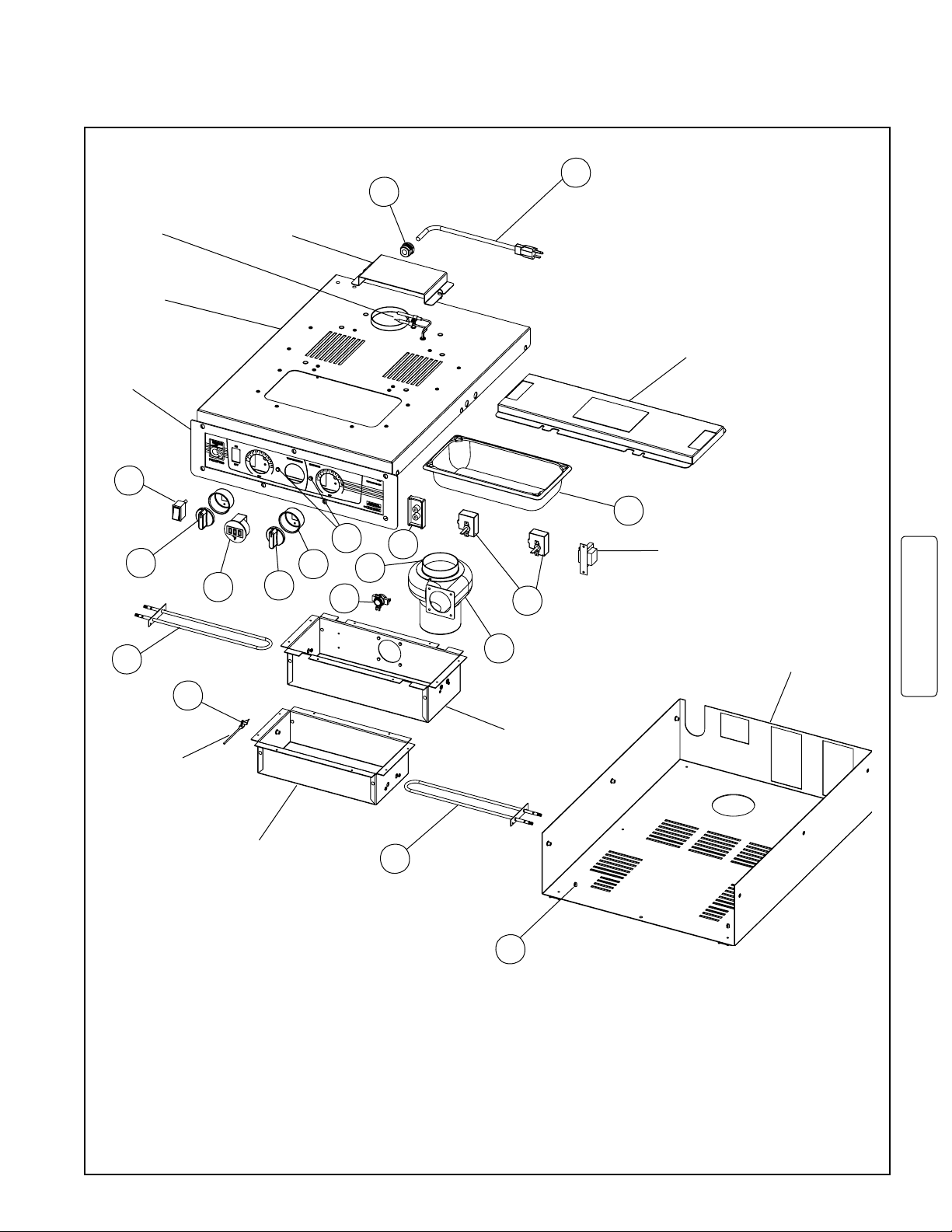
SERVICE and REPLACEMENT PARTS (continued)
C5-PM1500X EXPORT PROOFING MODULE
43
HEAT THERMOSTAT
BULB &
THERMOMETER
SENSOR
MODULE
CHASSIS
CONTROL
PANEL
30
32
36
AIR INTAKE
COVER
34
32
35
42
38
44
45
33
48
TRANSFORMER
SUPPLIED WITH
THERMOMETER
ITEM #36
AIR DISCHARGE
COVER
41
MOISTURE
THERMOSTAT
BULB
47
WATER PAN
ENCLOSURE
41
39
AIR DUCT
49
BOTTOM COVER
220-240 volt
FOR REPLACEMENT C5-PM1500X MODULE, ORDER ITEM #53 ON PAGE 14
19
Page 22
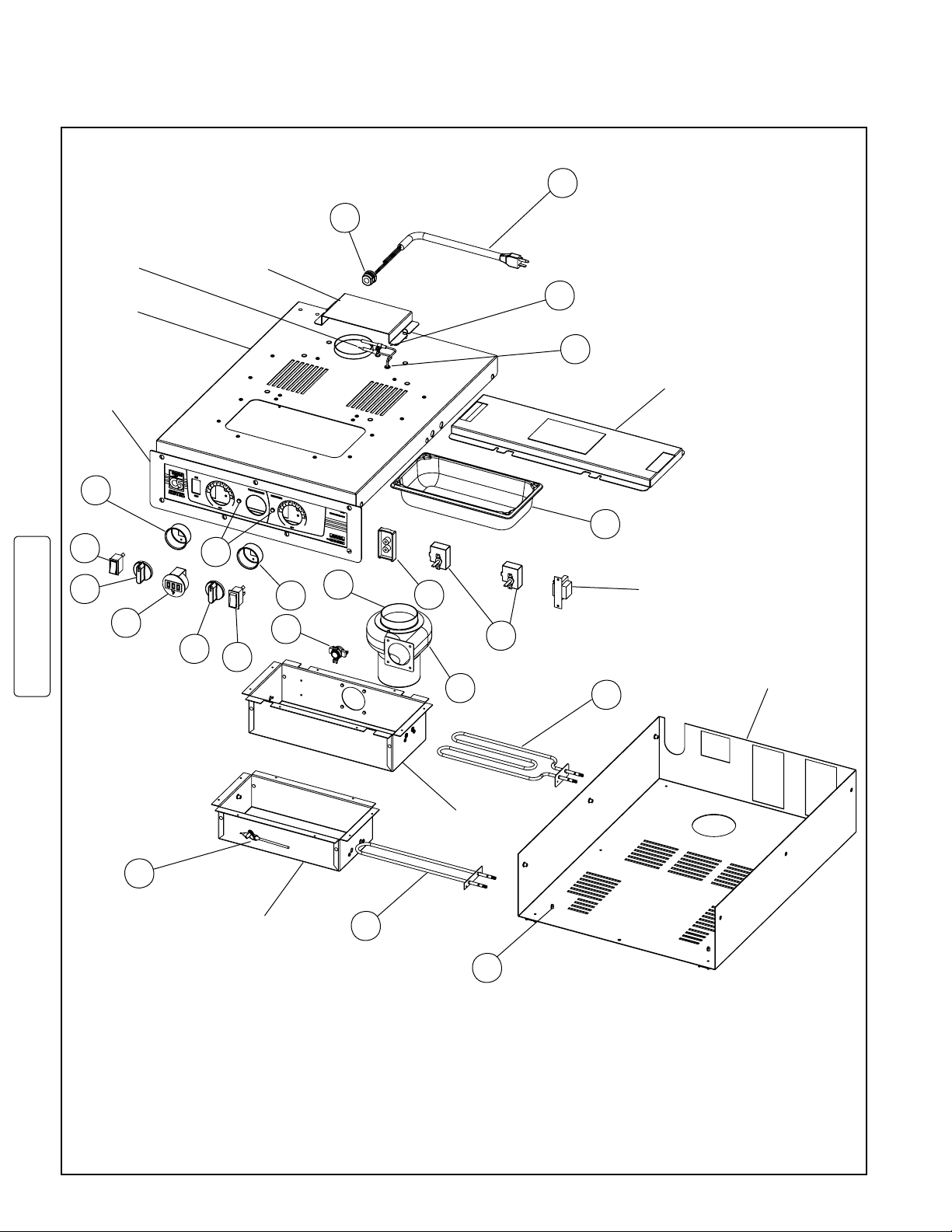
SERVICE and REPLACEMENT PARTS (continued)
C5-MM2000X EXPORT MOISTURE HOLDING MODULE
43
HEAT THERMOSTAT
BULB &
THERMOMETER
SENSOR
MODULE
CHASSIS
CONTROL
PANEL
34
30
32
36
220-240 volt
32
INTAKE
COVER
35
31
34
42
38
44
45
39
33
47
46
48
TRANSFORMER
SUPPLIED WITH
THERMOMETER
ITEM #36
40A
AIR DISCHARGE
COVER
BOTTOM COVER
AIR DUCT
47
MOISTURE
THERMOSTAT
BULB
WATER PAN
ENCLOSURE
50
49
FOR REPLACEMENT C5-MM2000X MODULE, ORDER ITEM #54 ON PAGE 14
20
Page 23
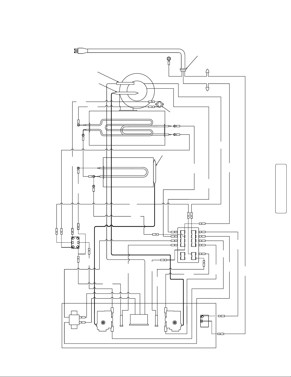
SERVICE and REPLACEMENT PARTS (continued)
19"
BLK
19"
WHT
27" WHT
10"BLK
16"
BLK
25"BLK
10"BLK
25"
BLK
34"
BLK
240V 1950 W ELEMENT
E
E
19
19
Z
Z
8
A
2
8
20
3
23
22
MASTER
POWER
SWITCH
HEAT
THERMOSTAT
AMBER
LIGHT
THERMOMETER
220-240V 50/60HZ
TO 12V DC TRANSFORMER
24
10
17
13
23
22
21
20
7
10
2
3
4
17
18
24
23
12116
5
22
21
20
19
10
9
8
7
16
15
14
13
4
3
2
1
TERM BLOCK
Z
7
WHITE
BLACK
GREEN
GRN GROUND SCREW
POWER CORD 250VAC 15A
STRAIN RELIEF
13
1
AIR DUCT
THERMAL CUT-OUT
THERMOMETER SENSOR
HEAT THERMOSTAT BULB
BLOWER MOTOR
1
30"BLK
30" BLK
25" WHT
30"
BLK
8.50"
BLK
10"
BLK
16"
BLK
25"
BLK
19"BLK
10"
BLK
16"BLK
16" BLK
240V 675 W ELEMENT
240V 675 W ELEMENT
MOISTURE
THERMOSTAT
BULB
WATER PAN ENCLOSURE
MOISTURE
THERMOSTAT
AMBER
LIGHT
TOP OF MODULE
8
B
C
21
4
B
8
CONTROL PANEL
19
8
8
24
X
X
X
X
SELCTOR
SWITCH
E
D
C
17
17
E
B
B
B
A
NEMA 6-15P PLUG
°C
WIRING DIAGRAM
C5-CM2000X EXPORT COMBO MODULE
220-240 volt
21
Page 24
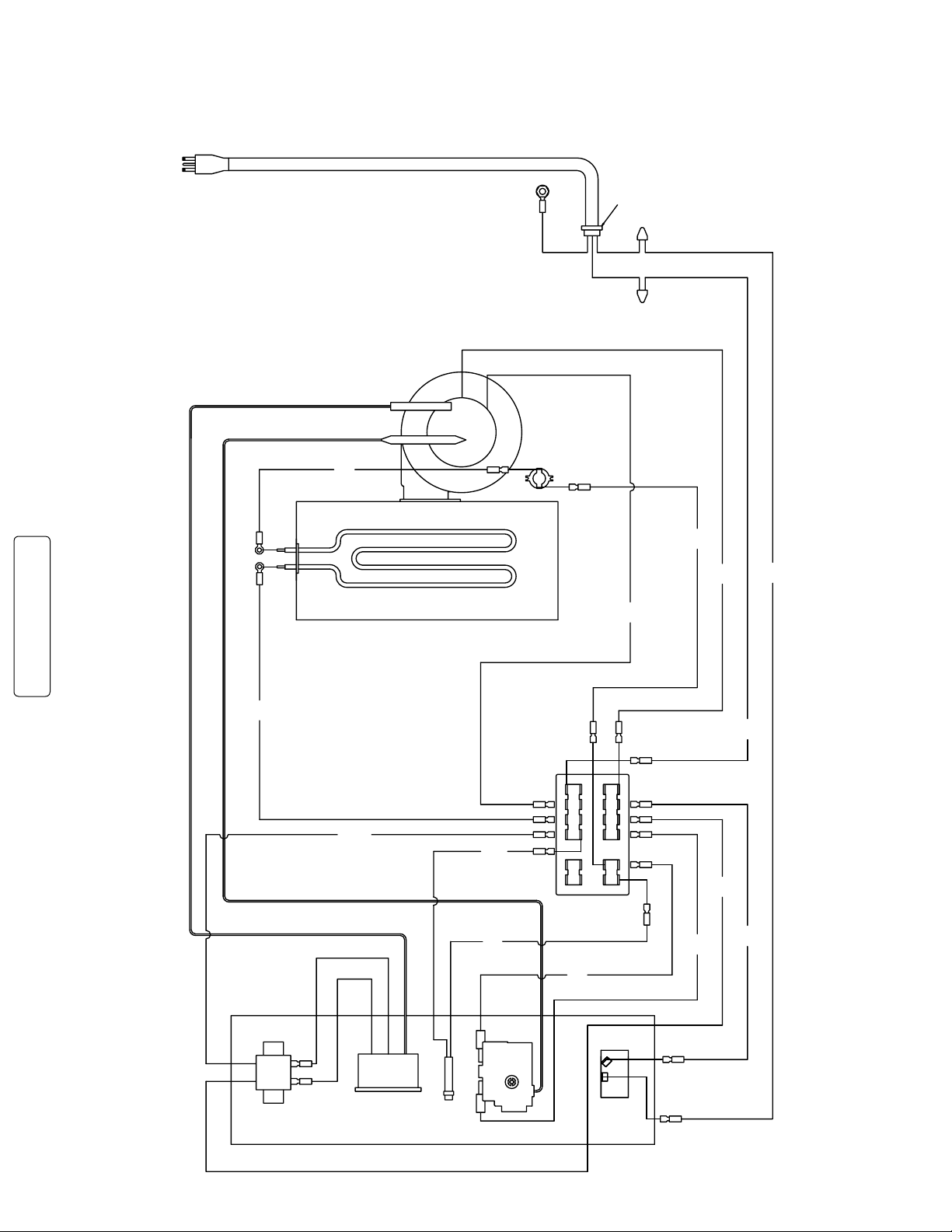
SERVICE and REPLACEMENT PARTS (continued)
STRAIN RELIEF
A
3
10
24
POWER CORD 250VAC 15A
GRN GROUND SCREW
GREEN
BLACK
WHITE
BLOWER MOTOR
HEAT THERMOSTAT BULB
THERMOMETER SENSOR
THERMAL CUT-OUT
240V 1950 WATT ELEMENT
AIR DUCT
TERMINAL BLOCK
220-240V 50/60HZ TO
12V DC TRANSFORMER
THERMOMETER
AMBER
LIGHT
HEAT
THERMOSTAT
MASTER
POWER
SWITCH
TOP OF CONTROL PANEL
1
2
3
4
13
14
15
16
7
8
9
10
19
20
21
22
5
61112
23
24
18
17
4
3
2
10
1
20
21
22
23
24
19
17
1
Z
2
19
17
20
Z
22
23
4
21
3
A
25"
BLACK
8.50"
BLACK
10"
BLACK
10"
BLACK
16"
BLACK
30"
BLACK
30"
BLACK
30"
BLACK
19"
BLACK
25"
BLACK
19"
WHITE
25"
WHITE
16"
BLACK
25"
BLACK
A
A
17
°C
NEMA 6-15P PLUG
WIRING DIAGRAM
C5-HM2000X EXPORT HOLDING MODULE
220-240 volt
22
Page 25
T2
20
3
23
22
MASTER
POWER
SWITCH
HEAT
THERMOSTAT
AMBER
LIGHT
THERMOMETER
220-240V 50/60HZ TO
12V DC TRANSFORMER
24
10
17
13
23
22
21
20
7
10
2
3
4
17
18
24
23
12116
5
22
21
20
19
10
9
8
7
16
15
14
13
4
3
2
1
TERMINAL BLOCK
Z
7
WHITE
BLACK
GREEN
GRN GROUND SCREW
POWER CORD 250VAC 15A
STRAIN RELIEF
13
1
AIR DUCT
THERMAL CUT-OUT
THERMOMETER SENSOR
HEAT THERMOSTAT BULB
BLOWER MOTOR
1
8
10"
BLACK
30"
BLACK
30"
BLACK
27"
BLACK
19"
WHITE
25"
WHITE
30"
BLACK
8.50"
BLACK
10"
BLACK
16"
BLACK
25"
BLACK
19"
BLACK
10"
BLACK
16"
BLACK
16"
BLACK
16"
BLACK
25"
WHITE
17
A
2
A
A
27"
WHITE
9"
BLACK
240V 675 W ELEMENT
240V 675 W ELEMENT
MOISTURE THERMOSTAT BULB
WATER PAN ENCLOSURE
MOISTURE
THERMOSTAT
AMBER
LIGHT
TOP OF MODULE
8
8
T2
21
4
T2
T2
CONTROL PANEL
19
Z
19
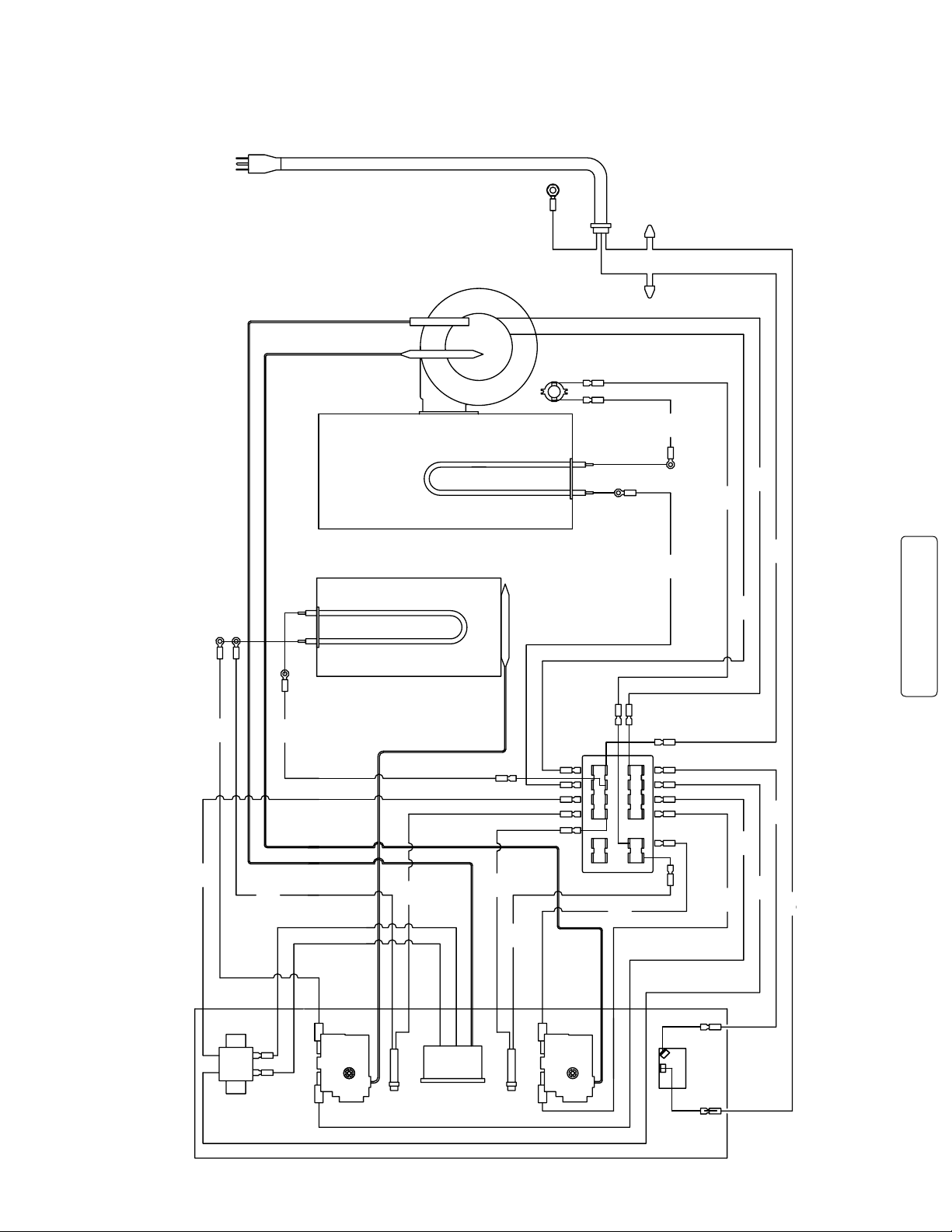
NEMA 6-15P PLUG
°C
SERVICE and REPLACEMENT PARTS (continued)
WIRING DIAGRAM
C5-PM1500X EXPORT PROOFING MODULE
220-240 volt
23
Page 26
SERVICE and REPLACEMENT PARTS (continued)
21
T2
MOISTURE
THERMOSTAT
CONTROL PANEL
4
TOP OF MODULE
AMBER
LIGHT
MOISTURE THERMOSTAT BULB
240V 1360 W ELEMENT
10"
BLACK
27"
WHITE
17
25"
WHITE
16"
BLACK
16"
BLACK
16"
BLACK
10"
BLACK
19"
BLACK
25"
BLACK
16"
BLACK
10"
BLACK
8.50"
BLACK
30"
BLAC
K
25"
WHITE
27"
BLACK
30"
BLACK
30"
BLACK
8
1
BLOWER MOTOR
HEAT THERMOSTAT BULB
THERMOMETER SENSOR
THERMAL CUT-OUT
AIR DUCT
1
13
STRAIN RELIEF
POWER CORD 250VAC 15A
GRN GROUND SCREW
GREEN
BLACK
WHITE
7
Z
TERMINAL BLOCK
1
2
3
4
13
14
15
16
7
8
9
10
19
20
21
22
5
61112
23
24
18
17
4
3
2
10
7
20
21
22
23
13
17
10
24
120V TO
12V DC TRANSFORMER
°C
THERMOMETER
AMBER
LIGHT
HEAT
THERMOSTAT
MASTER POWER
SWITCH
22
23
3
20
10"
BLACK
240V 590W ELEMENT
WATER PAN ENCLOSURE
3
3
T2
T2
A
A
2
27"
WHITE
27"
BLACK
NEMA 6-15P PLUG
C
C
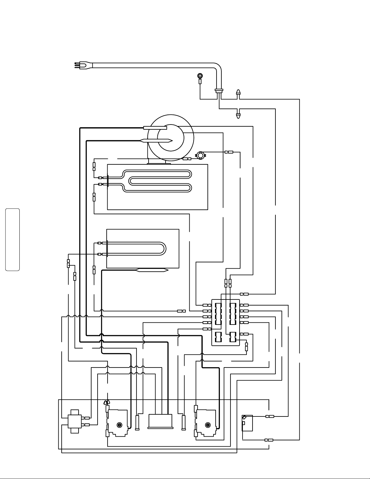
WIRING DIAGRAM
C5-MM2000X EXPORT MOISTURE HOLDING MODULE
220-240 volt
24
 Loading...