

Page 1
8 Series
TM
Controlled
Temperature
Heated Holding
Cabinets
User ManUal
This manual covers cabinets with electrical ratings
of: 120V 2000W, 120V 1440W & 220-240V 1681-2000W.
When ordering
electrical parts,
always confirm the
rating listed on rear
cabinet data plate.
Differences on voltage,
amps or wattage are
listed with bold text
in replacement part
descriptions.
Metro Heated Cabinets are for
Hot Food Holding applications only
InterMetro Industries Corporation
Wilkes-Barre, PA 18705
570-825-2741 www.metro.com
Page 2

1. With the POWER switch OFF, plug the supply power cord into an appropriate,
grounded, receptacle. (refer to the cabinet data plate for voltage and
ampere rating).
2. Ensure that the cabinet’s floor duct and water pan are installed. (refer to
the cabinet operating instructions). This helps to distribute the heat evenly
throughout the cabinet.
3. If extra humidity is desired, fill the water pan in the floor duct of the cabinet with
clean warm water. The capacity of the reservoir is about one quart (one liter).
4. Set the POWER switch to the ON position.
5. The cabinet will initially display the current temperature set point and then
show the actual cabinet temperature.
6. The temperature display will continue to blink until the temperature set point
is reached.
7. To change temperature set point, turn the control knob. As the knob is turned,
the temperature display will show the changing temperature set point, and the
“°F and °C” indicator lamps will blink. About 3 seconds after the knob is turned,
the display will show the actual cabinet temperature.
8. Press and release “Recall Set Points” button to see the current temperature
set point.
9. To see the current low temperature alarm set point, press and release the “Low
Temp Alarm” button. To change the low temperature alarm set point, press and
hold the “Low Temp Alarm” button, turn the temperature knob to the desired
setting, and release the button.
10. To clean cabinet, turn power off, unplug from wall outlet, allow the cabinet to
cool, remove the floor duct and pan, wipe the cabinet with a damp cloth and
dry with a towel.
11. Consult the user manual for additional operation and maintenance information.
Page 3
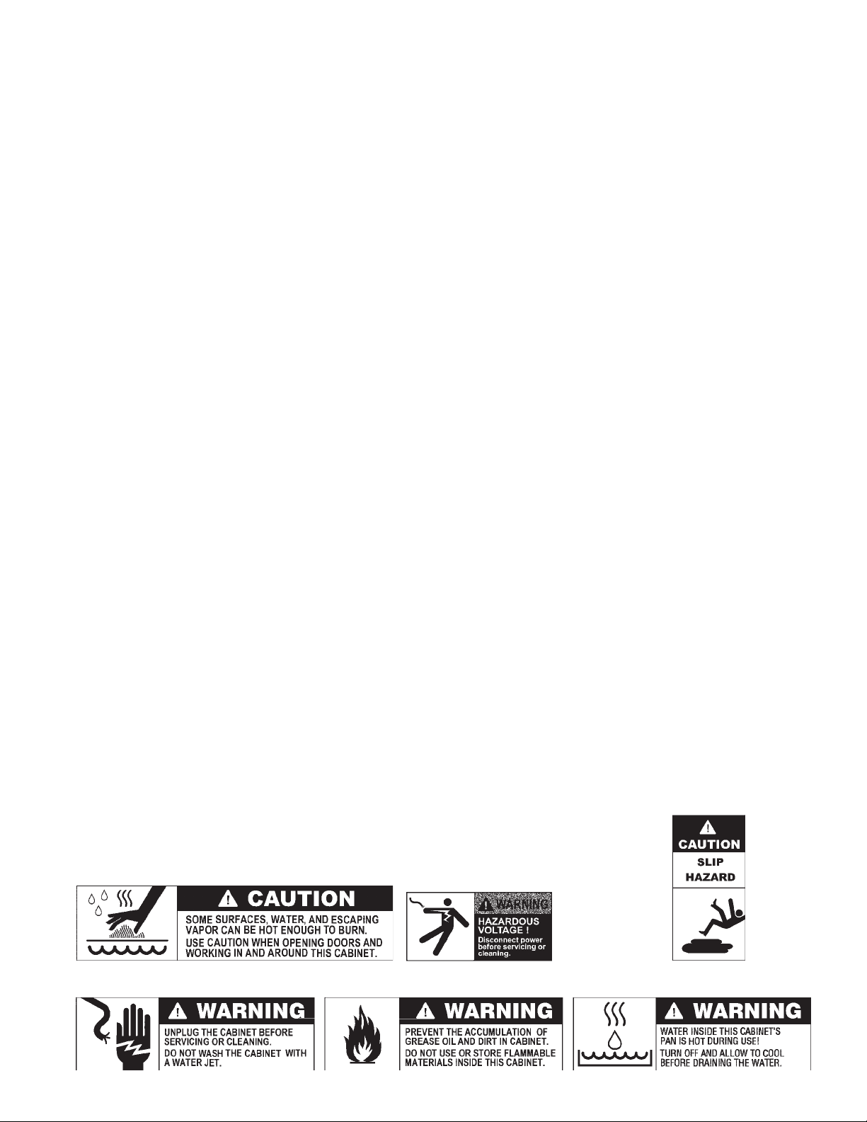
TABLE OF CONTENTS
SECTION PAGE
I. Basic Operating Guidelines ......Inside Front Cover
II. Safety Instructions .............................................. 1
III. Identifying Your Cabinet .................................... 2
IV. Installation & Set-up ........................................... 3
V. Product Features ............................................... 7
VI. Operating Instructions ....................................... 8
VII. Care & Maintenance .......................................... 9
VIII. Basic Troubleshooting ....................................... 10
IX. Service & Replacement Parts ............................ 11
X. Warranty ................................... Inside Back Cover
SAFETY INFORMATION
WARNING: Follow all food safety guidelines. Pre-heat the cabinet to the desired temperature before placing
cooked, hot food into the cabinet. This is not a re-thermalizing cabinet. Food must be at the
appropriate temperature before being placed into this cabinet. Use a food probe to check internal food
temperature — the cabinet temperature is not necessarily the internal food temperature.
WARNING: Only factory approved service agents should attempt to service, repair or replace electrical
components, wiring or power cord.
WARNING: Unplug the cabinet before cleaning or servicing. Do not wash the cabinet with a water jet or high
pressure water.
WARNING: This cabinet is for hot food holding applications only.
CAUTION: Do not spray or pour water into the top of the cabinet (control enclosure). To clean the cabinet, wipe
with a damp cloth and dry with a towel. Use only cleaning agents approved for stainless steel or
aluminum (depending on your cabinet construction).
CAUTION: Water dripping onto the floor from open doors can be a slip hazard.
1
Page 4

IDENTIFYING YOUR CABINET
CABINET SIZE (HEIGHT)
9 = FULL
7 = 3/4
5 = 1/2
3 = UNDER COUNTER
For future reference, note the serial and model number,
found on the data plate of the cabinet, here.
Serial number
Model number
Date the cabinet was
put into service
Fill out and return the warranty card located at
the back of this manual.
PART NUMBERING
C5 8 9 X S FS - L P FS A
CABINET NAME
CABINET TYPE
8 = 8 SERIES
(CONTROLLED TEMPERATURE )
ELECTRICAL CABINET RATING
BLANK = 120V 2000W
L = 120V 1440W
X = 220-240V, 50/60HZ, 1681-2000W
MATERIAL
S = STAINLESS
N = ALUMINUM
MODEL NO.
C58XX-X-XXXX
XXXV XXHZ XXXXXW
2/08
Serial No. C5800XXXX
A = ACCESSORIES
(IF APPLICABLE)
REAR DOOR(S)
(PASS THRU)
BLANK = NON-PASS THRU
FS = FULL SOLID
DS = DUTCH SOLID
FC = FULL CLEAR
DC = DUTCH CLEAR
CABINET CONSTRUCTION
BLANK = NON-PASS THRU
P = PASS-THRU, DOORS
(FRONT & REAR)
SLIDES
L = LIP LOAD (FIXED)
U = UNIVERSAL (ADJUSTABLE)
FRONT DOOR(S)
FS = FULL SOLID
DS = DUTCH SOLID
FC = FULL CLEAR
DC = DUTCH CLEAR
2
Page 5
INSTALLATION AND SET-UP
1. Check for Shipping Damage: Check the packaging and cabinet for shipping damage before and after unloading
the unit, and after removing all the packaging.
2. The receiver of this product is responsible for filing freight damage claims. This equipment must be opened
immediately for inspection. All visible damage must be reported to the freight company within 48 hours and must
be noted on freight bill at the time of delivery.
3. Concealed damage is your responsibility — you must advise the carrier of any loss or damage within 15 days
after receipt of the cabinet. If there is damage, retain the original packaging for inspectors.
4. After unpacking the cabinet, remove all tape and packing material from the inside as well as outside of the unit.
5. Any protective covers (plastic or paper sheet) on the sheet metal or clear door(s), if applicable, must also be
removed before turning the cabinet on.
WARNING: Only factory approved service agents should attempt to service, repair or replace electrical
components, wiring or the power cord.
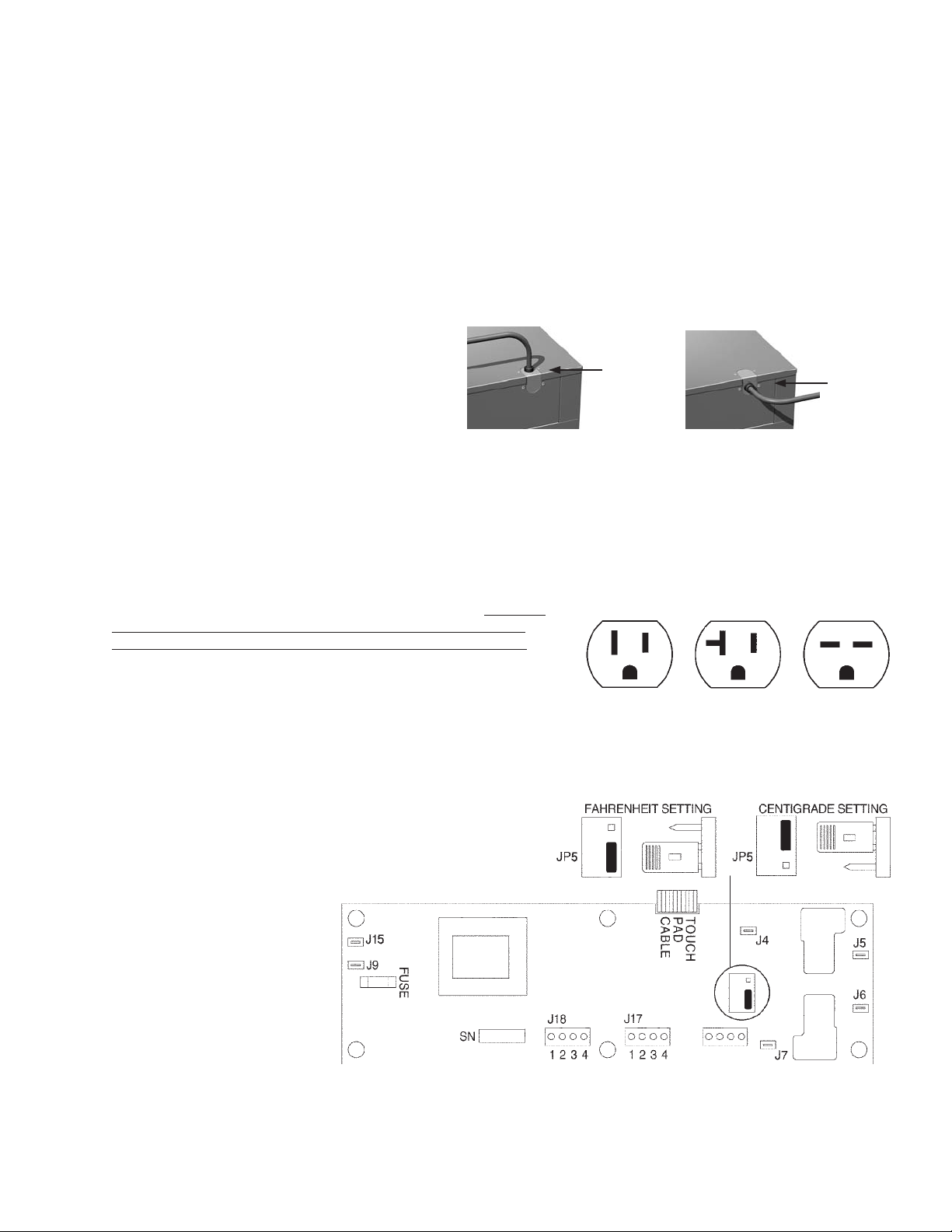
6. The power cord can be installed to exit the back
of the cabinet for wall outlets or out the top of the
cabinet for ceiling power drops. To change the
position of the power cord, first make sure the
cabinet power switch is off and the power cord is
unplugged from any electrical outlet. Remove the
(7) screws holding the cabinet top in place. Lift
the rear portion of the cabinet top and slide it
away from under the front control bezel, removing it from the cabinet. Remove the (2) screws on the rear of the
cabinet that hold the cord bracket in place. Rotate the power cord bracket 90° to the desired position and reattach
it with the (2) screws to the back of the cabinet. Make sure the green ground wire connection and the wire nuts on
the black and white wires have not loosened. Do not alter
the wiring of the power cord to the cabinet. Replace the
cabinet top and the (7) screws holding it in place.
7. Refer to the data plate located near the power cord for the electrical
specifications of cabinet. With the POWER switch OFF, plug the
cord into the appropriate rated, grounded receptacle. Cabinets
rated at 120V 2000W must be plugged into 125VAC 20 amp
receptacle and must be used on an individual branch circuit.
Cabinets rated at 120V 1440W may be plugged into either a
15 amp or 20 amp receptacle. Cabinets rated at 220-240V
1681-2000W must be plugged into a 250VAC, 15 amp receptacle.
8. The factory setting for temperature is Fahrenheit. To change the temperature display from Fahrenheit to Celsius a
jumper needs to be changed on the back of the controller circuit board. Turn the cabinet off, unplug the cabinet from
the electrical supply and remove the top of the cabinet (refer to step #6). See the control wiring diagram below for the
location of jumper JP5. For Fahrenheit control, the jumper
is on the lower two pins. For Centigrade control, move the
jumper from the lower two pins to the upper two pins.
After changing the jumper, replace the top, plug the
cabinet in, turn the cabinet on and adjust the
temperature and low temperature alarm settings
for the new units (°C or °F) of temperature selected.
9. Your C5 cabinet is designed
to operate next to walls and
other kitchen equipment.
However, the greater the
clearance around the sides
and the top of the cabinet,
the cooler the electrical
components will operate.
This may result in a longer
life expectancy for the
electrical components.
120V 120V 220/240V
15AMP 20AMP 15AMP
Outlet Outlet Outlet
Cord out
of the top
Cord out
of the
back
WARNING: Do not allow combustible materials to be stored or accumulate on, under or next to the cabinet.
Do not block any ventilation louvers or slots.
3
Page 6
INSTALLATION AND SET-UP (continued)
SLIDE INSTALLATION
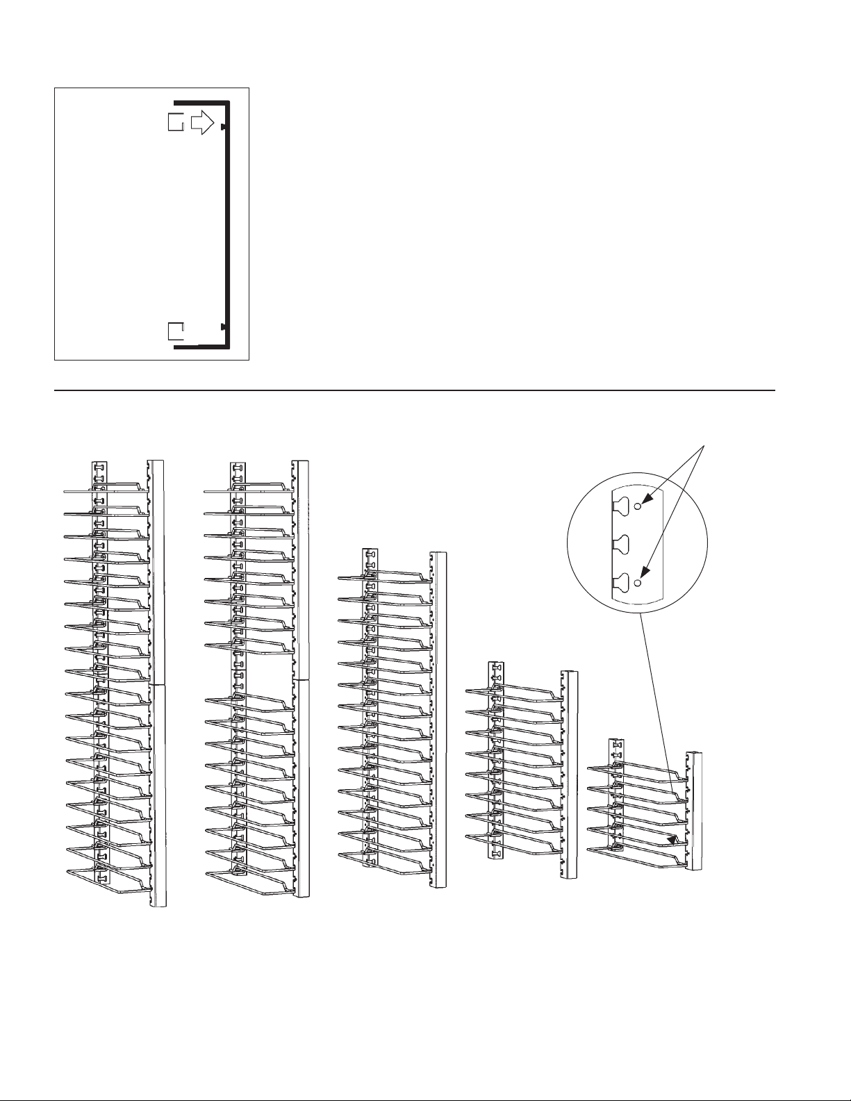
The rack uprights
have been installed
at the factory. If
removed for cleaning,
reinstall by hanging
them on the shoulder
rivets on the side
walls of the cabinet.
TOP VIEW
SLIDE POSITION to MAXIMIZE
3" PAN CAPACITY OF UNIVERSAL SLIDES
SiteSelect™
features
make slide
installation
easier.
Full Height Full Height
Single Door Dutch Doors Cabinet Cabinet Cabinet
18 Levels 17 Levels 14 Levels 8 Levels 5 Levels
(Position 2
from Bottom) (Position Bottom) from Bottom) from Bottom) (Position Bottom)
Part No. C5-U-9 Part No. C5-U-9 Part No. C5-U-7 Part No. C5-U-5 Part No. C5-U-3
Slides sold in pairs. For additional pair of wire slides, order C5-USLIDECPR.
nd
3
/4 Height
(Position 2nd (Position 3rd
4
1
/2 Height Under Counter
Page 7
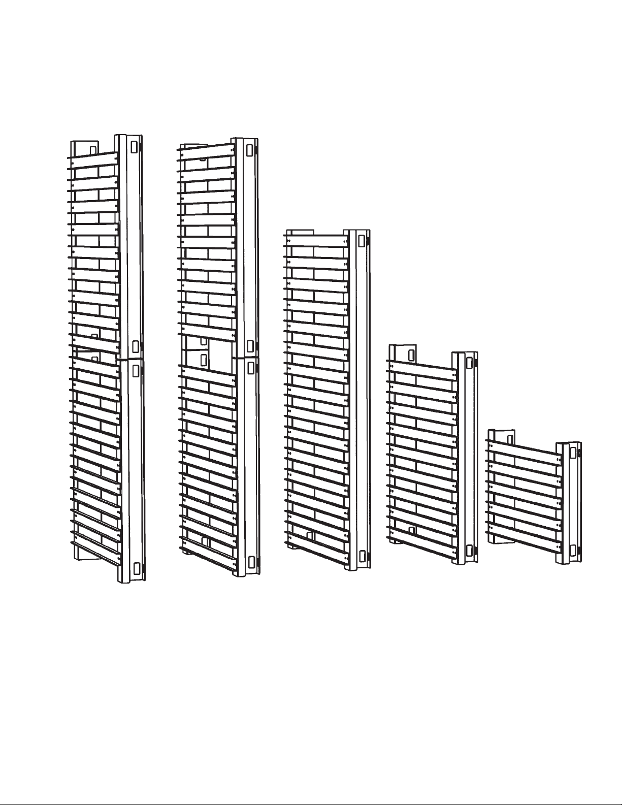
INSTALLATION AND SET-UP (continued)
CORRECT ORIENTATION OF
LIP LOADED SLIDE RACKS
Full Height Full Height
Single Door Dutch Doors Cabinet Cabinet Cabinet
2-piece Construction 2-piece Construction 1-piece Construction 1-piece Construction 1-piece Construction
Part No. C5-L-9 Part No. C5-L-9 Part No. C5-L-7 Part No. C5-L-5 Part No. C5-L-3
Slides sold in pairs.
3
/4 Height
5
1
/2 Height Under Counter
Page 8
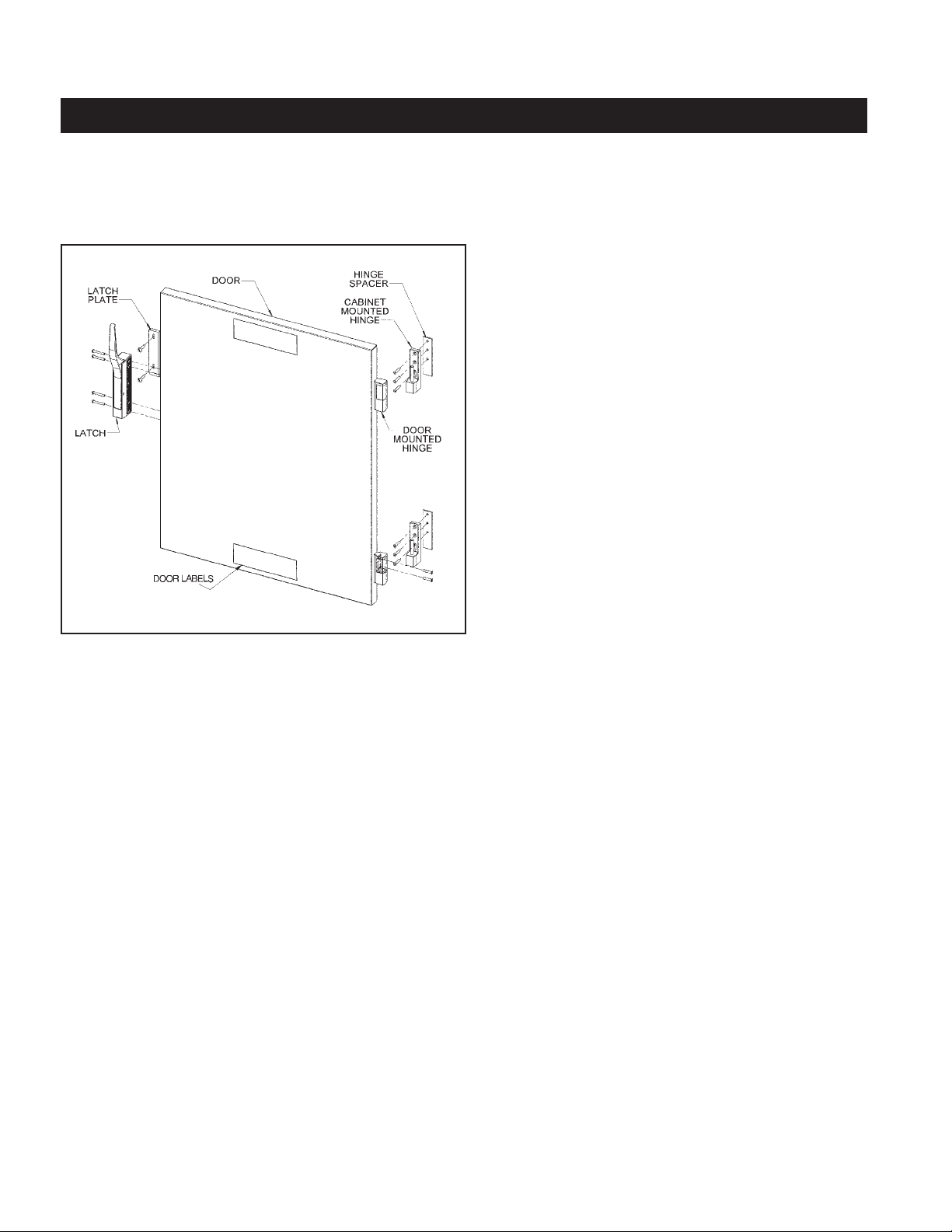
REVERSING THE DOORS
WARNING • TIP HAZARD
Tip Hazard: On Pass-Thru cabinets that include any clear doors, when field reversing, the front and back doors
must be hinged from opposite sides of the cabinet. See illustration below.
Clear Doors
Hinged on
opposite
sides of
the cabinet
After reversing the door hinging direction, labels are now
upside down. You may contact InterMetro for a new set
of labels, part number RPC5-DRLBL, at no charge, to be
placed in the proper orientation.
C5 doors are normally hinged on the right hand side at the factory. If the cabinet has been in operation, allow the
door to cool before reversing the door hinging direction. Note: When finished, all holes will have screws in them and
there will be no exposed holes left in the cabinet.
1. If the cabinet has Dutch Doors, note which is the top and which is the bottom door. Open the door, lift it off the
cabinet hinges and set it aside noting which is the top and bottom of the door.
2. On the cabinet, remove the latch strike plate and hinges and install them on the other side of the cabinet. On the
door, remove the hinge covers to access the mounting screws. Remove the hinges.
3. Rotate the door so the previous bottom is now the top and install the hinges. On Dutch Doors, do not remove the
handles, the top door becomes the bottom and the bottom door the top. On single door units, rotate the handles
180° and reinstall.
4. On the cabinet mounted hinges, lift the white bushing and rotate it 180° and push it down to reseat it on the
hinge pin.
5. Install the door onto the cabinet hinges and check to make sure the door latches properly and the gaskets
are in compression.
Clear Doors
Hinged on
same side
of the
cabinet
6
Page 9
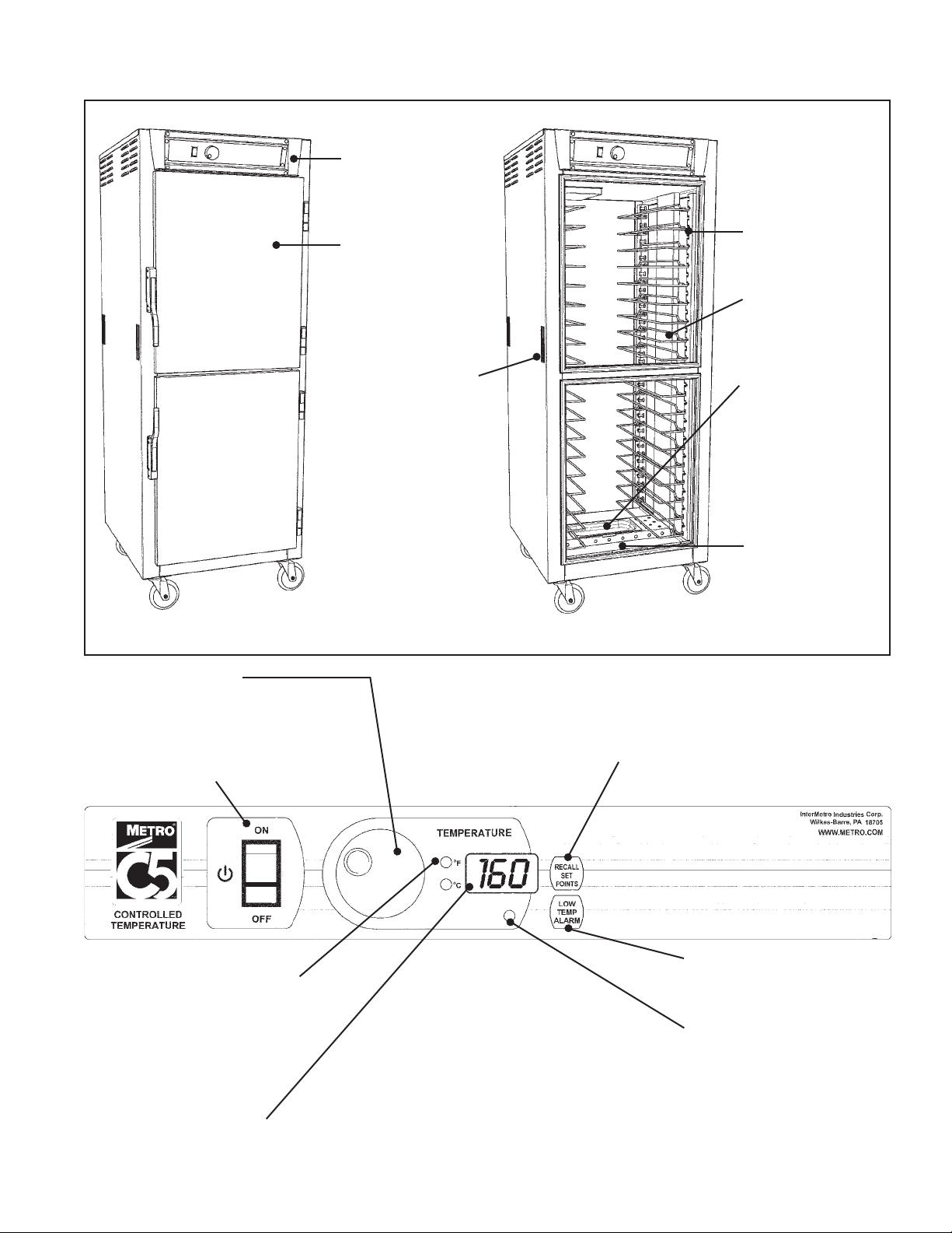
PRODUCT FEATURES
Control Panel
Field Reversible
Doors
Be careful when
opening the doors
as hot, humid air will
escape the cabinet.
Flush Pull Handles
Temperature Control
Controls the temperature in the cabinet.
Turn the knob to change the temperature
set point. The display shows new set
point as the knob is turned.
Power Switch
Tray Slides
Air Duct
Water Pan
Fill with water.
Capacity is
1 quart (1 liter).
Floor Duct
Holds water
pan and evenly
distributes air flow.
Set Point Recall
Displays cabinet’s
temperature set point.
Temperature Scale Indicators
Set to Fahrenheit in the factory.
These indicators will also blink
while the temperature set point
is being displayed.
Air Temperature Display
Displays the current cabinet
temperature. Also displays low
temperature warning.
Audio Disable (Sound Off)
Press “Recall Set Points” and “Low
Temp Alarm” buttons simultaneously
and hold for five seconds to toggle
sound off and on.
7
Low Temperature Alarm
Sets and recalls the low
temperature alarm set point.
Element Cycling
Indicator Light
Indicates air heat
element is on.
Page 10
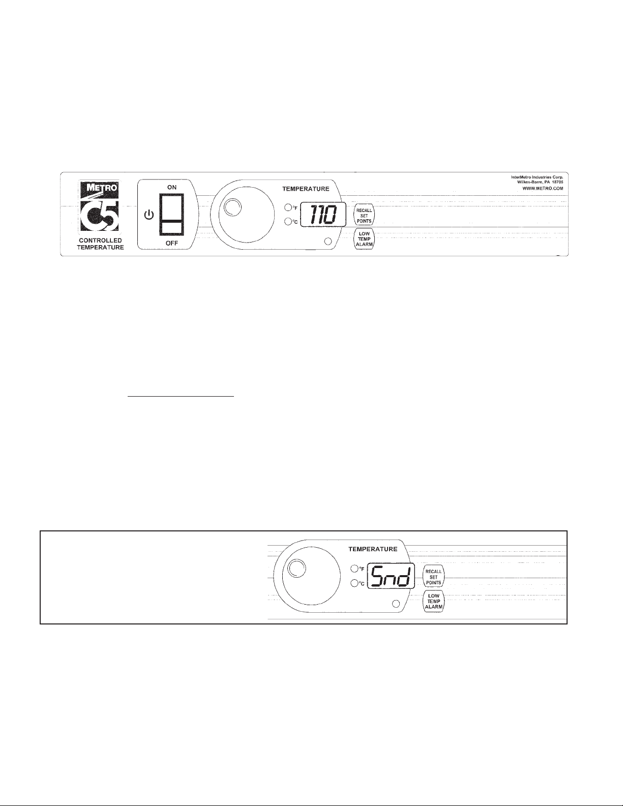
OPERATING INSTRUCTIONS
Power-Up & Pre-Heat
• When the cabinet is switched on, the controller displays “Set Pnt” followed by the current temperature set point.
The temperature display will begin to blink, indicating that the cabinet is pre-heating. The display will stop
blinking after the temperature set point is reached.
• Factory preset is 160°F (71°C).
• Turn “Temperature” knob at any time to change the desired setting.
• Press the “Recall Set Points” button at any time to display the current temperature setting.
1. Allow the cabinet to pre-heat without food for 30 minutes to an hour. The time required to reach the temperature
set point is dependent on the set point, the size of the cabinet, the door type (solid or clear) and the temperature
of the room the cabinet is in. Factory preset is 160°F (71°C).
Warning: Follow all food safety guidelines. Pre-heat the cabinet to the desired temperature before putting cooked,
hot food into the cabinet. This is not a re-thermalization cabinet. Food must be at the appropriate
temperature before being placed into this cabinet.
Low Temperature Alarm
• The Cabinet is equipped with a low temperature alarm system that will alert you if the cabinet falls below the
alarm set point for more than 5 minutes during operation (unless the low temperature alarm has been disabled
— see below). The TEMPERATURE display will begin to blink “L0” alternating with the current temperature. An
audible alarm will also sound 3 times every 10 seconds (See “Sound On and Off” below for more information on
the audio alarm)
• Factory preset for the low temperature alarm is 140°F (60°C).
• To check the existing low temperature alarm set point, press and release the LOW TEMP ALARM button.
• To change the low temperature alarm set point, press and hold the LOW TEMP ALARM button while turning the
TEMPERATURE knob.
• If the cabinet’s temperature set point is set below the low temperature alarm set point, the alarm is disabled.
• The low temperature alarm is also disabled during pre-heat.
Sound On and Off
Press “LOW TEMP ALARM” and “RECALL
SET POINTS” and hold for 5 seconds to
toggle sound off and on. Display will show
“SND OFF” or “SND ON”
2. Your C5 8 Series cabinet is capable of creating hot humid air. As you operate the cabinet and open and close
the door(s), condensation may form on the inside surfaces of the cabinet. Some dripping of water may occur to
the outside of the cabinet particularly at the door seals. Water may also drip off opened doors onto the floor.
Caution: Water dripping onto the floor from open doors can be a slip hazard.
Warning: Some surfaces, water and escaping vapor can be hot enough to burn. Use caution when opening doors
and working in and around this cabinet.
8
Page 11
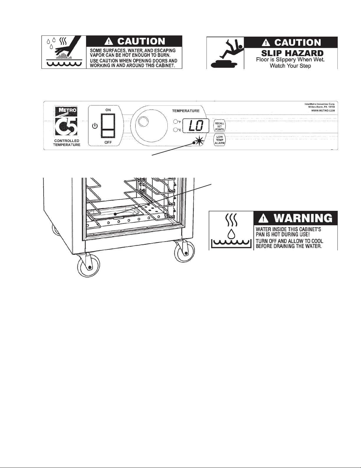
3. The cabinet control will “remember” its setting when the cabinet is turned off. Therefore, when the unit is turned
on the setting will be the same as it was during the previous use.
4. A red indicator light below the digital display indicates when the temperature heater element is energized.
As the control setting is adjusted, it may take a few moments for the status of the indicator light to reflect the
new control setting and cabinet condition depending on when in the control cycle the setting is changed.
Element Indicator
5. If humidity is required, fill the water pan in the bottom of the cabinet. Potable (suitable for drinking) water should
be used.
Water Pan
Fill with water. Capacity is about
1 quart (1 liter).
6. To remove the water from the water pan, allow the cabinet and water to cool and remove the water pan.
Note: When turning the cabinet off at the end of the work day, it is recommended to leave the door(s) open to
prevent heat and condensation build up within the cabinet.
Note: If the cabinet is not going to be used for an extended period of time, all water should be removed from the
water pan and the cabinet completely cleaned and dried out.
CARE & MAINTENANCE
Cleaning The Cabinet
Warning: Unplug the cabinet before cleaning or servicing. Do not wash the cabinet with a water jet or high
pressure water.
Caution: Do not spray or pour water into the control enclosure. To clean the cabinet, wipe with a damp cloth and
dry with a towel. Use only cleaning agents approved for stainless steel or aluminum (depending on your
cabinet construction).
Caution: Do not use cleaners with chlorides or phosphates as they may cause damage to stainless steel. Do not
use strong alkalis on aluminum as they may discolor it.
1. Use cleaners in the proper concentrations. Follow the manufacturer’s directions for the cleaning product used.
After using any cleaning products, thoroughly rinse all surfaces to remove all residue.
2. Use a damp cloth or sponge. Mild soap suitable for stainless steel and aluminum is acceptable. Dry with a
clean towel. Wipe up spills as soon as possible and regularly clean the cabinet to avoid staining and difficult to
clean conditions.
If the control knob needs to be removed for cleaning, use a 5/64" Allen key to loosen the set screw on the control
knob. Remove the knob, clean the control face and/or knob and replace the knob and tighten the set screw.
9
Page 12

BASIC TROUBLESHOOTING
Warning: Only factory approved service agents should attempt
to service, repair or replace electrical components,
wiring or power cord.
1. Controls do not work (no display or indicator light):
a. Check that the cabinet is plugged in.
b. Check that the outlet has power.
c. Check that the power switch is in the “On” position.
d. Check the cabinet wiring from the power cord to the power switch and to the controller.
e. Check that the fuse on the back of the controller is not blown.
f. Controller is faulty.
2. Controller temperature display does not change (displays a constant value approximately equal to the
minimum or maximum of the temperature control range, 70°F (21°C) or 200°F (93°C):
a. The temperature sensor and controller are not communicating:
i. Temperature sensor wires are broken or disconnected from the controller.
ii. Controller needs to be replaced.
iii. Temperature sensor needs to be replaced.
3. Temperature too hot:
a. Set point is too high. Turn temperature set point down to the desired temperature.
b. During initial pre-heat some over temperature may occur but will quickly return to the set point.
c. If displayed temperature exceeds 220°F (104°C):
i. Blower wiring is faulty or disconnected.
ii. Blower needs replacing.
iii. The thermostat may have failed and the thermal overload device is controlling the temperature. Stop using
the cabinet immediately and contact a factory approved service agent.
4. Temperature too low:
a. The cabinet may still be in pre-heat or recovering from a door being opened.
b. Set point is too low. Turn temperature set point up to the desired temperature.
c. A door is not closed or sealing properly.
d. Blower is not circulating air:
i. Blower wiring is faulty or disconnected.
ii. Blower needs replacing.
5. No heat generated
a. If the heat indicator light is on but the cabinet does not draw approximately 16 amps for 120V 2000W units;
12 amps for 120V 1440W units; or 8 or 9 amps for 220-240V units:
i. Air heater element may be faulty.
ii. The wiring to the air heater element may be faulty or disconnected.
iii. The controller (air heater relay) may be faulty.
b. If the heat indicator light does not come on, the controller may be faulty.
6. Displays blink “LO” and Alarm beeps (if “Sound” is on):
a. If the temperature display alternately blinks the current cabinet temperature and then “LO”, refer to steps 4 and 5.
7. Cabinet trips GFCI (ground fault circuit interrupter):
A GFCI receptacle protects against “ground faults” whenever an electrical product is plugged into the GFCI
outlet by constantly monitoring the electricity for any loss of current. If the current flowing out of the receptacle
differs by a small amount from that returning, the GFCI quickly switches off power to that circuit. The GFCI
interrupts power extremely fast to minimize the possibility of an electric shock.
a. The heater element may absorb some moisture into its casing and insulation during shipment or during long
periods of not being used (such as during the summer in a closed school kitchen). Plug the cabinet (without
water in the water pan) into a non-GFCI outlet, set the temperature to 200°F (93°C) and let it run for 30-60
minutes to dry out any moisture the element may have absorbed. (If it trips the standard circuit breaker call
factory approved service agent.) After drying the element, plug the cabinet into the GFCI outlet; the cabinet
should run without tripping the GFCI.
b. If the cabinet still trips the GFCI, call a factory approved service agent.
Note: The temperature control does not require field calibration.
10
Page 13
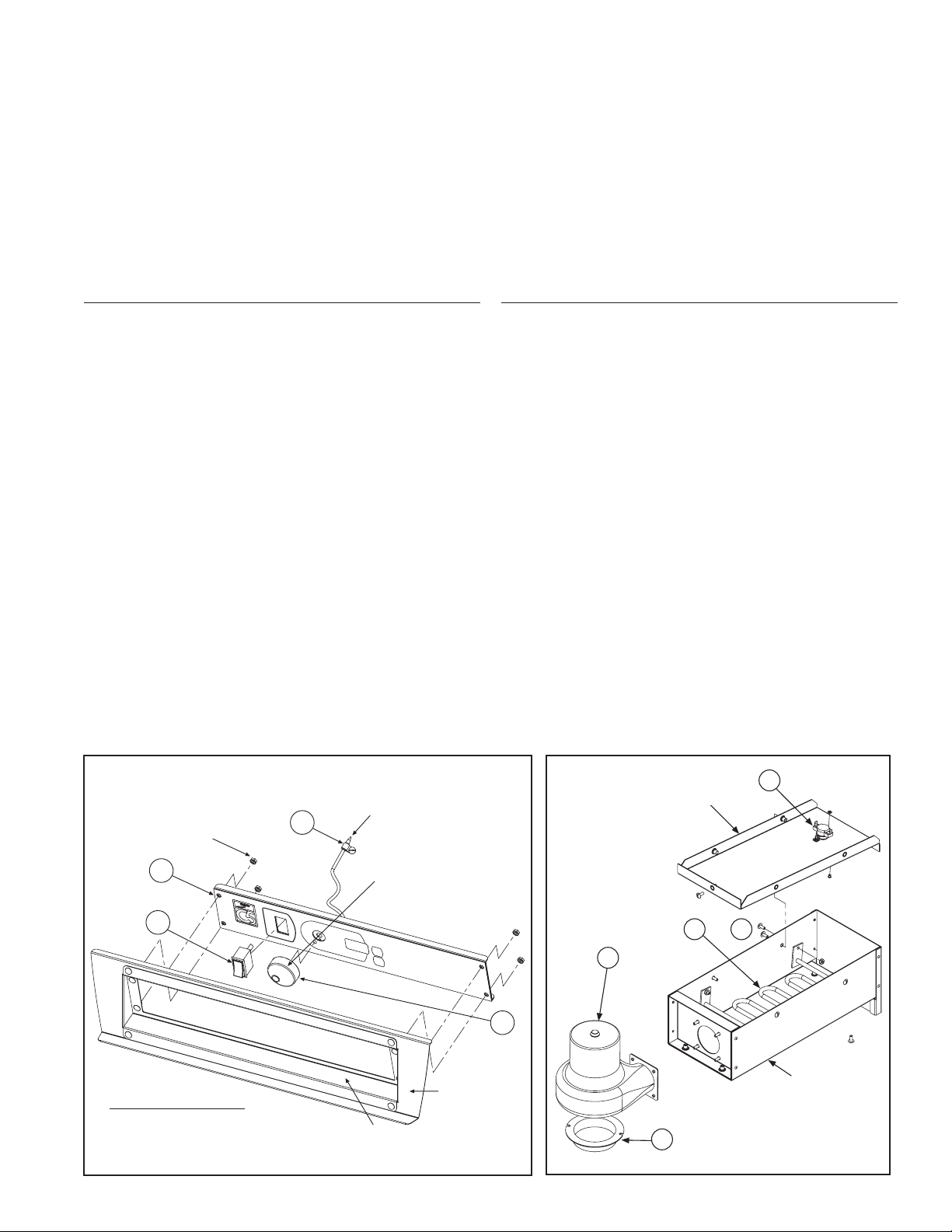
6
OR 6A
7
5
AIR DUCT
COVER
4
AIR DUCT
AIR DUCT
CONTROL PANEL
12
1
2
BEZEL
FACE PLATE
TEMPERATURE SENSOR
REMOVE (4)
NUTS
3
SET SCREW ATTACHMENT
SET SCREW
ATTACHMENT
SERVICE and REPLACEMENT PARTS
C5 8 SERIES REPLACEMENT PARTS — ELECTRICAL
Confirm the cabinet electrical rating before ordering components.
Warning: Only factory approved service agents should attempt to service, repair or replace electrical components,
wiring or power cord.
To access the controller area, remove the (7) screws holding the cabinet top in place. Lift the rear portion of the
cabinet top and slide it away from under the front control bezel, removing it from the cabinet. After servicing, replace
the cabinet top and the (7) screws holding it in place.
120V 1440W OR 2000W
ITEM # Replacement Part No. Description
1 RPC5-8CONTR 120V (°F) CONTROLLER,
SENSORS & WIRING
2 RPC13-127 MASTER SWITCH
3 RPC5-KNOB CONTROLLER KNOB
4 RPC11-191 INTAKE COLLAR
5 RPHM20-2103 BLOWER, 120V
6 RPC13-093 ELEMENT, 120V 1950W
6A RPC13-114 ELEMENT, 120V 1360W
7 RPC13-198 THERMAL CUT OUT
8 RPC13-099 POWER CORD, 120V 20A
RPC13-217 CORD, TWIST LOCK PLUG, 20A
RPQC13-001 CORD, RT ANGLE PLUG, 20A
8A RPC13-017 POWER CORD, 120V 15A
9 RPC13-098 STRAIN RELIEF, 20A CORD
9A RPC13-083 STRAIN RELIEF, 15A CORD
10 RPC13-096 TERMINAL BLOCK
11 RPC07-055 SENSOR CABLE GROMMET
12 RPC5-SCLP SENSOR CLAMP & SCREW
220-240V 1681W OR 2000W
ITEM # Replacement Part No. Description
1 RPC5X-8CONTR 220-240V (°C) CONTROLLER,
SENSORS & WIRING
2 RPC13-127 MASTER SWITCH
3 RPC5-KNOB CONTROLLER KNOB
4 RPC11-191 INTAKE COLLAR
5 RPHX20-2103 BLOWER, 220V-240V
6 RPC13-117 ELEMENT, 240V 1950W
7 RPC13-198 THERMAL CUT OUT
8 RPC13-247 POWER CORD, 250V 15A
9 RPC13-083 STRAIN RELIEF, 15A CORD
10 RPC13-096 TERMINAL BLOCK
11 RPC07-055 SENSOR CABLE GROMMET
12 RPC5-SCLP SENSOR CLAMP & SCREW
11
Page 14

SERVICE and REPLACEMENT PARTS (continued)
C5 8 SERIES REPLACEMENT PARTS — CABINET BODY
ITEM # Replacement Part No. Description
CABINET BODY
13 RPC06-873B FULL HEIGHT DOOR GASKET
RPC06-873C
RPC06-873A
3
/4 HEIGHT DOOR GASKET
1
/2 HEIGHT & DUTCH
DOOR GASKET
RPC06-873D UNDER COUNTER DOOR
GASKET
14 RPC5-S9DR STAINLESS STEEL FULL
HEIGHT SOLID DOOR
RPC5-S7DR STAINLESS STEEL 3/4 HEIGHT
SOLID DOOR
RPC5-S5DR STAINLESS STEEL 1/2 HEIGHT
& BOT D SOLID DOOR
RPC5-S9TDDR STAINLESS STEEL TOP
DUTCH SOLID DOOR
RPC5-S3DR STAINLESS STEEL UNDER
COUNTER SOLID DOOR
RPC5-N9DR ALUMINUM FULL HEIGHT
SOLID DOOR
RPC5-N7DR ALUMINUM 3/4 HEIGHT SOLID
DOOR
RPC5-N5DR ALUMINUM 1/2 HEIGHT &
BOT D SOLID DOOR
RPC5-N9TDDR ALUMINUM TOP DUTCH
SOLID DOOR
RPC5-N3DR ALUMINUM UNDER
COUNTER SOLID DOOR
RPC5-S9CDR STAINLESS STEEL FULL
HEIGHT CLEAR DOOR
RPC5-S7CDR STAINLESS STEEL 3/4 HEIGHT
CLEAR DOOR
RPC5-S5CDR STAINLESS STEEL 1/2 HEIGHT
& BOT D CLEAR DOOR
RPC5-S9CTDDR STAINLESS STEEL TOP
DUTCH CLEAR DOOR
RPC5-S3CDR STAINLESS STEEL UNDER
COUNTER CLEAR DOOR
RPC5-N9CDR ALUMINUM FULL HEIGHT
CLEAR DOOR
RPC5-N7CDR ALUMINUM 3/4 HEIGHT
CLEAR DOOR
RPC5-N5CDR ALUMINUM 1/2 HEIGHT & BOT
D CLEAR DOOR
RPC5-N9CTDDR ALUMINUM TOP DUTCH
CLEAR DOOR
RPC5-N3CDR ALUMINUM UNDER
COUNTER CLEAR DOOR
ITEM # Replacement Part No. Description
CABINET BODY (continued)
15 RPC11-274 DOOR LATCH — 1 PIECE
RPC14-118A FLUSH HANDLE DOOR
LATCH — 1 PIECE
RPC14-251 DOOR LATCH WITH TWIST
LOCK — 1 PIECE
16 RPC14-042 DOOR HINGE —1 PIECE
17 B5DNB 5" BRAKE CASTER
B3B 3" BRAKE CASTER
RPQC02-248 6" BRAKE CASTER
18 B5DN 5" SWIVEL CASTER
B3 3" SWIVEL CASTER
B5DRN 5" RIGID CASTER
RPQC02-247 6" SWIVEL CASTER
19 RPC11-481 WATER PAN
20 RPC06-872 POCKET HANDLE
*21 C5-L-9 TALL CABINET LIP LOADED
SLIDE ASSEMBLY
C5-L-7
3
/4 HEIGHT CABINET LIP
LOADED SLIDE ASSEMBLY
C5-L-5
1
/2 HEIGHT CABINET LIP
LOADED SLIDE ASSEMBLY
C5-L-3 UNDER COUNTER CABINET
LIP LOADED SLIDE ASSEMBLY
*22 C5-U-9 TALL CABINET UNIVERSAL
SLIDE ASSEMBLY (INCLUDES
WIRE SLIDES & UPRIGHTS)
C5-U-7
3
/4 HEIGHT CABINET
UNIVERSAL SLIDE ASSEMBLY
(INCLUDES WIRE SLIDES &
UPRIGHTS)
C5-U-5
1
/2 HEIGHT CABINET
UNIVERSAL SLIDE ASSEMBLY
(INCLUDES WIRE SLIDES &
UPRIGHTS)
C5-U-3 UNDER COUNTER CABINET
UNIVERSAL SLIDE ASSEMBLY
(INCLUDES WIRE SLIDES &
UPRIGHTS)
23 C5-USLIDECPR UNIVERSAL WIRE SLIDES
— 1 PAIR
24 RPC5-SSLEG-1 EQUIPMENT LEG — QTY. 1
25 RPC5-DRLBL DOOR LABELS — QTY. 2
(USED WHEN REVERSING
DOORS)
26 C5-SHELF ACCESSORY SHELF (USED
WITH UNIVERSAL UPRIGHTS)
12
*See pages 4 and 5 for slide identification.
All slides sold as pairs.
Page 15
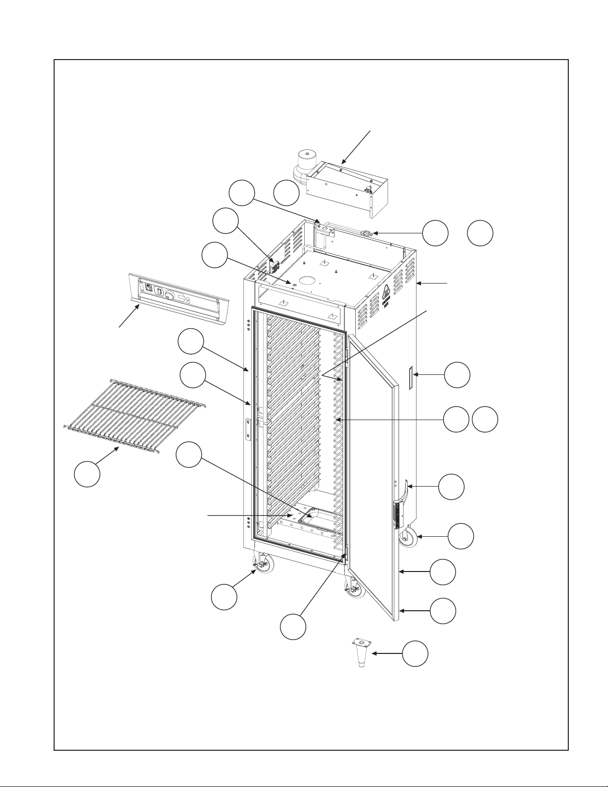
SERVICE and REPLACEMENT PARTS (continued)
Replacement Parts Diagram
AIR DUCT
See page 11.
9
or 9A
10
8
or 8A
11
CABINET BODY
SLIDE UPRIGHT
USED WITH ITEM #23
CONTROL PANEL
See page 11.
21
*
26
13
19
FLOOR DUCT
17
16
24
25
14
20
23
15
18
22
*
*For slide identification, see pages 4 and 5.
13
Page 16
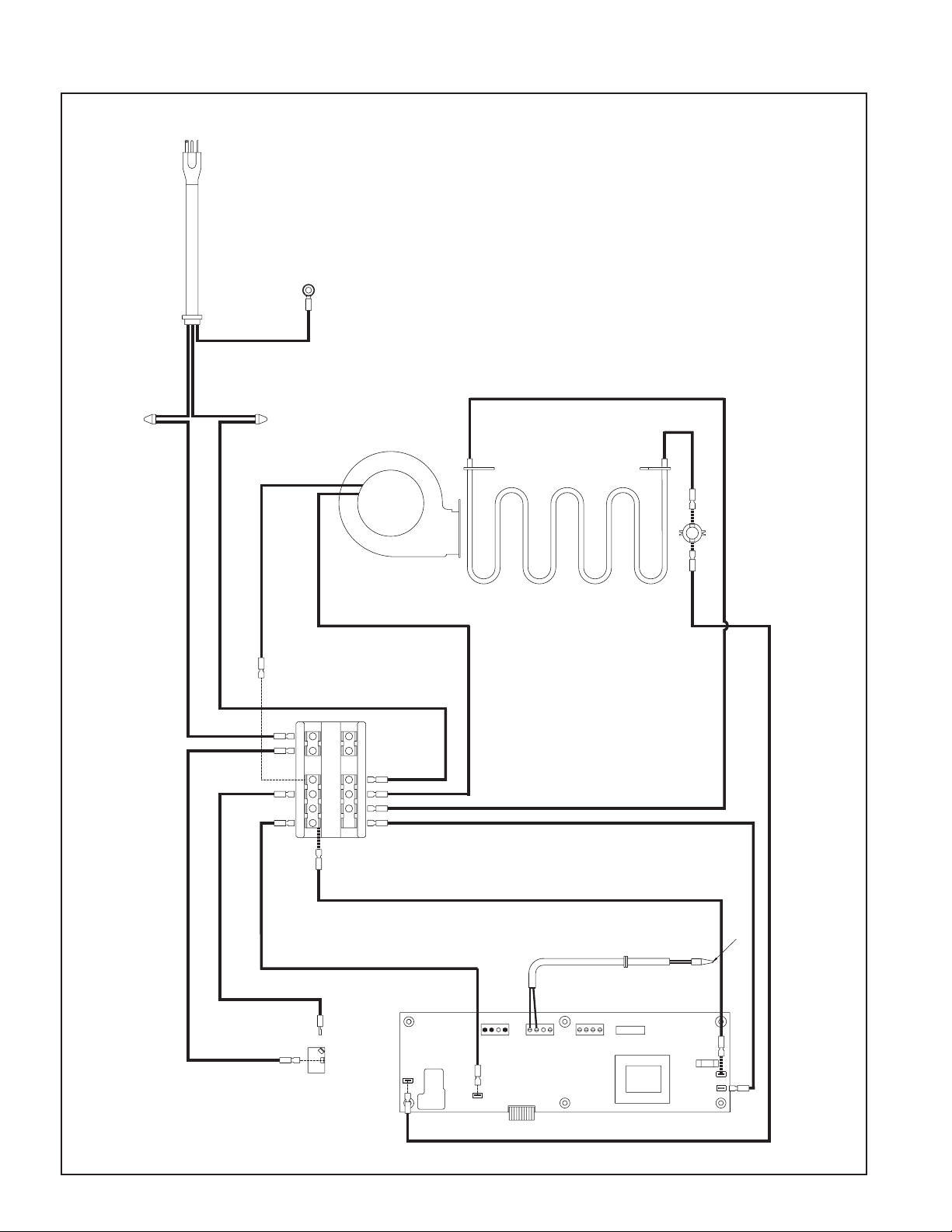
J9
J15
18
FUSE
SN
J17
6
BLOWER
THERMAL CUT OUT
A
J5
BLACK
WHITE
A
AIR ELEMENT
11
19
21
GROUND
STRAIN RELIEF
GREEN
WHITE
BLACK
POWER CORD
21
10
BLACK
WHITE
TEMPERATURE SENSOR
BLACK
BLACK
BLACK
BLACK
24
22
23 22 2124
18
17 16 1518
20 19
11 10 912
5 4 36
9
6 11 10
20
19
WHITE
BLACK
MASTER SWITCH
ON
OFF
20
22
CONTROLLER
J5
J4
GRAY X2
RIBBON CABLE
24
TOP
TERMINAL BLOCK
9
SERVICE and REPLACEMENT PARTS (continued)
Wiring Diagram
Warning: Only factory approved service agents should attempt
to service, repair or replace electrical components,
wiring or power cord.
14
Page 17
Thank you for purchasing a Metro C5 Controlled Temperature Cabinet.
We are certain you will be more than satisfied with its quality and
performance. Please fill in the warranty information space below
so we may register your warranty. Also, so that we may learn
more about our customers and hopefully be of continued
service in the future, please take a moment to
fill in the customer information space below.
Thank You
CUT ALONG DOTTED LINE
CUSTOMER INFORMATION
1. Which one of the following best describes
your establishment?
a. ❑ Full-Service Restaurant
b.❑ Banquet Hall
c. ❑ Hotel/Motel
d. ❑ Hospital/Nursing Home
e. ❑ College/University
f. ❑ School
g. ❑ Employee Feeding
h. ❑ Other
FOLD HERE — DO NOT DETACH
2. Please indicate the two product benefits that
were of major interest to you.
CUT ALONG DOTTED LINE
a. ❑ Easy-to-use controls
b. ❑ Door selection
c. ❑ Size Selection
d. ❑ Cabinet capacity
e. ❑ Slide selection
f. ❑ Easy-to-clean design
g. ❑ Other
WARRANTY INFORMATION:
Cabinet Model No.
Cabinet Serial No.
Date Purchased
Customer Name
Address
Phone No.
For warranty coverage, this card
must be returned to Metro.
3. Main factor that led to your decision to
purchase this product?
a. ❑ Product operating and functional features
b. ❑ Overall quality
c. ❑ Price
d. ❑ Availability
e. ❑ Other
4. Three sources that led to the purchase of
his product — in the order of their impact
(1 — being most impact; 3 — being least impact).
a. ❑ Trade Journal Ad
b ❑ Trade Show
c. ❑ Sales Call
d. ❑ Direct Mail
e. ❑ Previous Purchase
f. ❑ Other
15
Page 18
WILKES-BARRE PA 18705-9968
P O BOX A
ATTN: CUSTOMER SERVICE
INTERMETRO INDUSTRIES CORPORATION
POSTAGE WILL BE PAID BY
F IRS T-C LA SS P ER MI T N O. 1 21 W I LK ES -B ARR E, PA
BUSINESS REPLY MAIL
UNITED STATES
IN THE
IF MAILED
NECESSARY
NO POSTAGE
FOLD HERE — DO NOT DETACH
STAPLE HERE
STAPLE HERE
16
STAPLE HERE
Page 19
InterMetro Industries Corporation (hereinafter referred to asSeller) warrants to the
®
Page 20

InterMetro Industries Corporation
North Washington Street, Wilkes-Barre, PA 18705
For Product Information Call: 1-800-433-2232
Visit Our Web Site: www.metro.com
L01-425
Information and specifications are subject to change
without notice. Please confirm at time of order.
Rev. A 4/08
 Loading...