

Page 1

Scanner Support
6
The 700 Series Color Mobile Computer is available with imaging or laser
scanning technologies, including the following:
APS Linear Imager: (standard for 730 Computers)
— includes the EV10 Scan Engine
2D Imager: (not supported on 730 Computers)
— includes the IT4000 Scan Engine
1D Laser Scanner: (not supported on 730 Computers)
— includes the SE900, SE900HS, SE900-S6, and
SE900HS-S6 scan engine s
PDF417 Laser S canner: (not supported on
730 Computers)
A 700 Color Imager Demo application demonstrates the more common
features of the 700 Color Computer imager. See the Imager Demo V1.0
User’s Guide on the Intermec Developer’s Library CD for information.
Note: “700 Color” pertains to 740, 741, 750, 751, 760, and 761 Computers unless otherwise noted.
Reads 1D symbologies and PDF417 bar codes. Linear imaging u sing Vista Scanning tec hnology reads low-contrast bar
codes, laminated bar codes, and bar codes displayed on CRT
or TRT displays. This imaging us es harmless LEDs for illumination and does not require any warning labels. Vista Scanning is more reliable than lasers as it is a c ompletely solid state
with no moving parts or oscillating mirrors.
This decodes several stacked 1D and 2D symbologies, including PDF417, Data Matrix, and MaxiCode without “painting.” It can also read 1D codes from any orientation, for example the scan be am does not need to align perpendicular to
the symbol to read it. Photography is a secondary application;
the lens in the device favors bar code reading. Photos are
640x480, 256 gray-scale.
Traditional laser scanner that decodes 1D bar codes.
Higher speed laser scanner that can read PDF417 labels by
“painting” the label.
199700 Series Color Mobile Computer User’s Manual
Page 2

Scanner SupportChapter —6
Scanner Control and Data Transfer
Note: To use the methods described below, enable Data Collection functionality on the 700 Computer using the bootloader configuration menu.
The Data Server and associated software provide several ways to manipulate scanner control and data transfer between the scanner subsystem and
user applications:
S Automatic Data Collection COM Interfaces:
These COM interfaces allow user applications to receiv e bar code data,
and configure and control the bar code reader engine.
S ITCAxBarCodeReaderControl functions:
These ActiveX controls allow user applications to collect bar code data
from the scanner, to configure the scanner, and to configure audio and
visual notification when data arrives.
S ITCAxReaderCommand functions:
Use these ActiveX controls to modify and retrieve configuration information using the reader interface commands.
S Scanning EasySet bar code labels:
You can use the EasySetRbar code creation software from Intermec
Technologies Corporation to print configuration labels. Scan the labels
to change the scanner configuration and data transfer settings.
Use the Intermec EasySet software to print configuration labels you can
scan to change your configuration settings. For more information, see
the EasySet online help. EasySet is available from the Intermec Data
Capture web site.
For more information, see the SDK User’s Manual provided with your
Windows CE/PocketPC SDK.
200 700 Series Color Mobile Computer User’s Manual
Page 3

Data Collection Configuration
For Units with PSM Builds Older than 3.00
Scanner settings for the 700 Color Computer can be configured via the
Data Collection control panel applet. From the 700 Color Computer, tap
Start > Settings >theSystem tab > Data Collection.SeeAppendix A,
“Configurable Settings” for more information about the following parameters. Note that these are in alphabetical order.
S Codabar (page 298)
S Code 11 (page 312)
S Code 128 (page 301)
S Code 128 Options (page 302)
S Code 128 FNC1 Character (page 303)
S Code 39 (page 296)
S Code 93 (page 300)
6 Scanner Support—Chapter
S Code 93 Length (page 300)
S Data Matrix (page 314)
S Interleaved 2 of 5 (page 309)
S Matrix 2 of 5 (page 310)
S MaxiCode (page 315)
S MSI (page 305)
S PDF417 (page 306)
S Macro PDF (page 306)
S Micro PDF417 (page 308)
S Plessey (page 304)
S QR Code (page 313)
S Standard 2 of 5 (page 297)
S Telepen (page 311)
S UPC/EAN (page 299)
For Units With PSM Build 3.00 or Newer
You can configure scanner settings for the 700 Color Computer via the
Intermec Settings control panel applet. From the 700 Color Computer,
tap Start > Settings >theSystem tab>theIntermec Settings icon. See the
Intermec Computer Command Reference Manual (P/N: 073529) for information about the settings you can configure with this applet. This online
manual is available from the Intermec web site at www.intermec.com.
201700 Series Color Mobile Computer User’s Manual
Page 4
Scanner SupportChapter —6
Internal Scanners
The Intermec Internal Scanner feature allows Automatic Data Collection
(ADC) by accepting data from the COM 1 port and wedging it into the
keyboard interface. You can enable or disable this feature from the Today
screen on the 700 Color Computer.
For Unit s With PSM Build 3.00 or Newer
Do the following before you configure your internal scanner from the Intermec Settings control panel applet. Information about the settings you
can configure with this applet is described in the Intermec Computer Com-
mand Reference Manual. The online manual is available from the Intermec
web site at www. intermec.com.
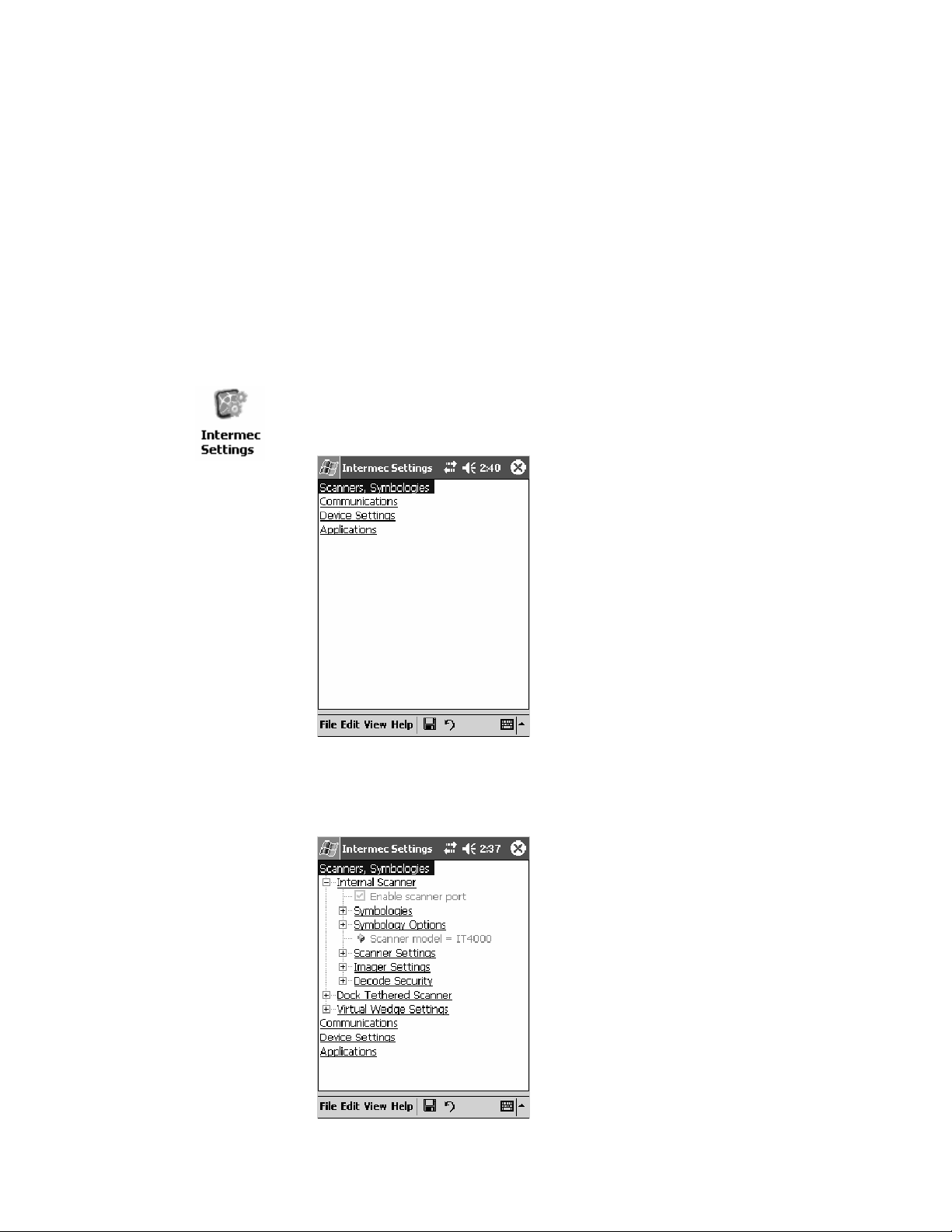
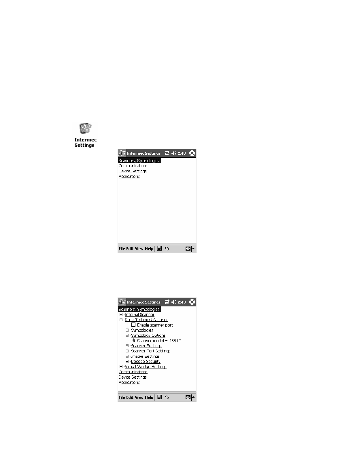
1 From the 700 Color Computer, tap Start > Settings >theSystem tab >
the Intermec Settings icon.
2 Tap the Scanners, Symbologies option, then tap (+) to expand Internal
Scanner. This sample screen is for the IT4000 scan engine.
202 700 Series Color Mobile Computer User’s Manual
Page 5

6 Scanner Support—Chapter
Scanner and Imager Settings
Depending on what is selected as the scanner model, image settings, decode security, scanner settings, and virtual wedge are configured from the
Intermec Settings applet. See the the Intermec Computer Command Refer-
ence Manual, available from the Intermec web site at www.intermec.com,
for more information about each enabled option.
Internal Scanner Supported Symbologies
See the following table for a guideline and Appendix B, “Bar Code Symbologies” for more information on each supported symbology:
Symbologies EV10 IT4000 SE900 SE900HS SE900-S6 SE900HS-S6
Code39 XX X X X X
UPC/EAN X X X X X X
Code 128 XX X X X X
Interleaved 2 of 5 X X X X X X
Code 93 XX X X X X
Codabar X X X X X X
Code 2 of 5 XX X X X X
MSI X X X X X X
Plessey XX X X X X
Code 11 X X X X X X
Matrix 2 of 5 XX X X X X
Telepen X X X X X X
PDF417 XX X X X X
Micro PDF417 X X X X X X
MaxiCode X
Data Matrix X
QR Code X
RSS 14 X X X X Available in f/w
Sxxp304
RSS Limited XX X XAvailableinf/w
Sxxp304
RSS Expanded X X X X Available in f/w
Sxxp304
Codablock A XX X X X X
Codablock F X X X X X X
UCC Composite X
Available in f/w
Sxxp304
Available in f/w
Sxxp304
Available in f/w
Sxxp304
203700 Series Color Mobile Computer User’s Manual
Page 6
Scanner SupportChapter —6
Tethered Scanners
The Intermec Tethered Scanner feature allows Automatic Data Collection
(ADC) by accepting data from the COM 1 port and wedging it into the
keyboard interface. You can enable or disable this feature from the Today
screen on the 700 Color Computer.
The following information is divided between units with PSM Builds older than 3.00 (next paragraph) or units with PSM Builds 3.00 or newer
(starting on page 209).
For Units With PSM Builds Older than 3.00
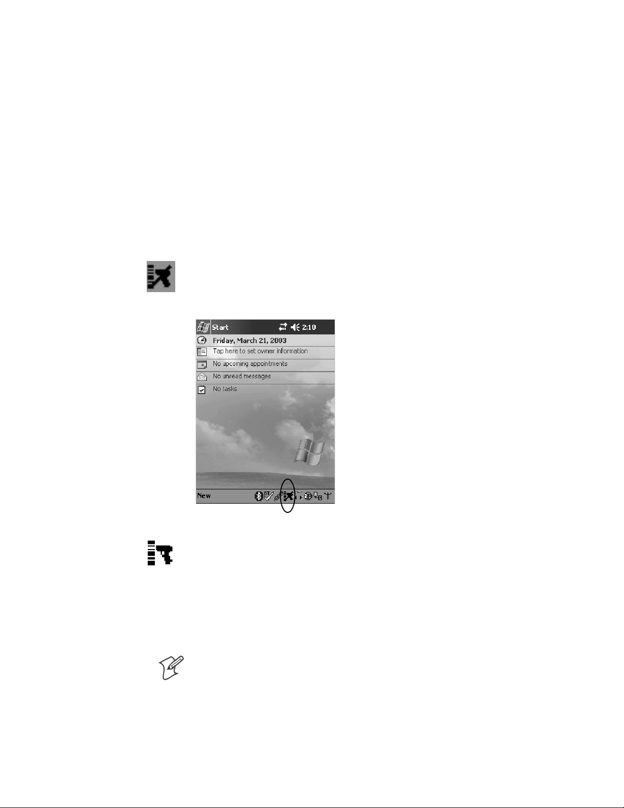
Enabling and Disabling
On the 700 Color Computer, tap Start > Today. Tap the bar code scannericonintheSystemTray(circled below). Initially, the bar code scanner
icon indicates that this feature is disabled (shown to the left).
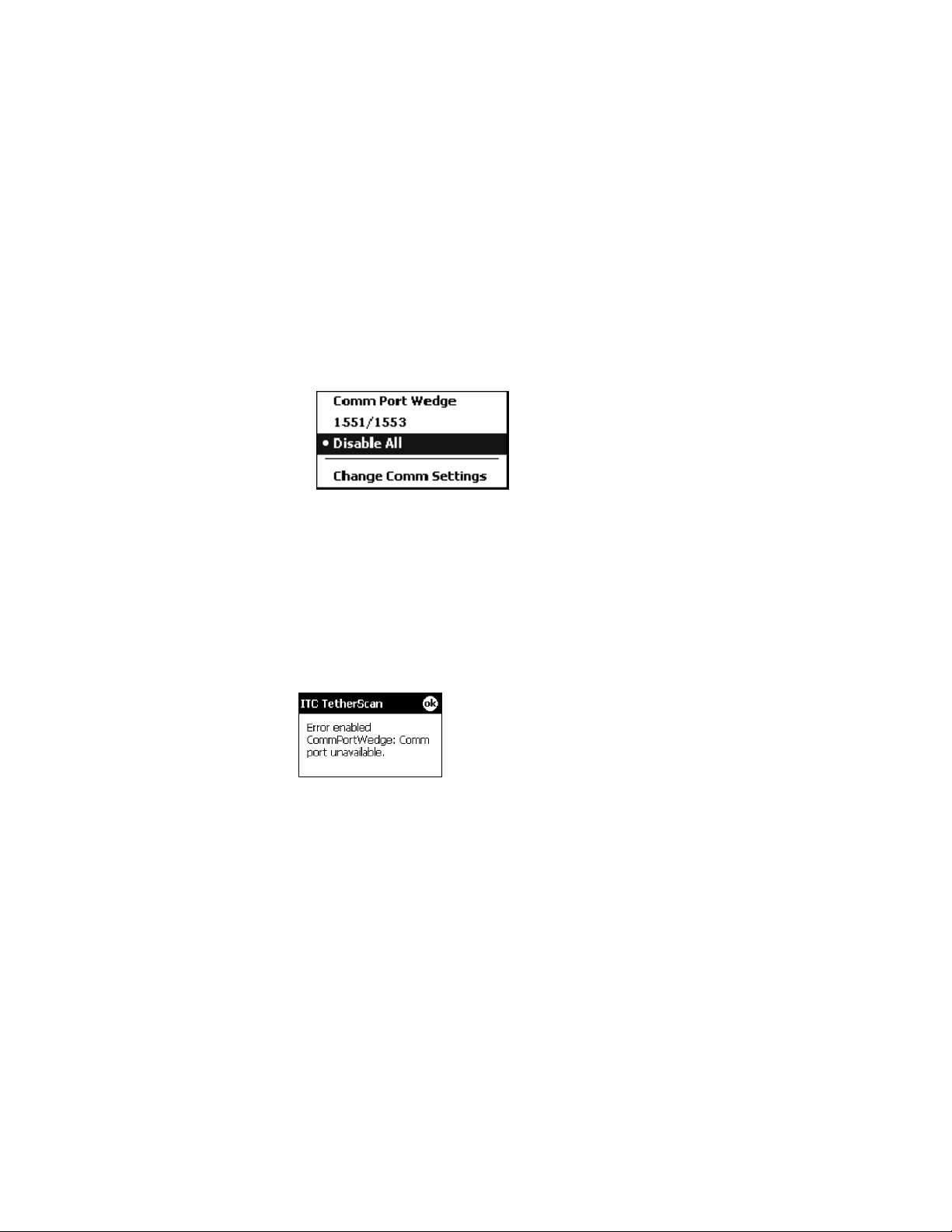
S Select Comm Port Wedge to send any data, coming into the 700 Color
Computer through the COM1 port from an external input device, as
keyboard data to an application on the desktop.
For example, if you have Pocket Word running on your 700 Color
Computer desktop, information scanned with a scanner connected to
the COM1 port appears in the Word document. If another data collection application is running and is active on the 700 Color Computer,
the scanned information appears in that application.
Note: When Comm Port Wedge is selected, regardless of the data sent
by the external input device, you cannot control the device or the data
format using any of the Intermec scanner control or data transfer APIs
from the SDK or the internal Data Collection software. The external
inputdeviceisgovernedbywhatsoftwareithasonboardtotellithow
to scan, take pictures, or send the data elsewhere.
204 700 Series Color Mobile Computer User’s Manual
Page 7
6 Scanner Support—Chapter
S Select 1551/1553 to enable the Sabre 1551E or 1553 Tethered Scanner
to scan, then send data as keyboard data. The 1551/1553 Tethered
Scanner has software onboard that translates scanned data into characters, so the r unning/active application does not need to know how to do
that. All the scanner control and data transfer APIs will work with the
1551/1553 Tethered Scanner, so you can control the device.
S Select Disable All to disable this feature and use the COM1 port for
another application, such as ActiveSync. An error message will result if
this option were not selected, but this action was attempted. Similarly, if
ActiveSync is using the COM1 port, and you select Comm Port Wedge
or 1551/1553, an error message will result. See “Error Message”for
more information.
Error Message
If the COM1 port is used by another application, such as ActiveSync, neither the Comm Port Wedge nor the 1551/1553 Tethered Scanner can be
enabled. As a result, the following message may appear. Note that this mes-
sage is for the Comm Port Wedge. You must disable that application to free
uptheCOM1portbeforeyoucanenableeitherthewedgeorthescanner.
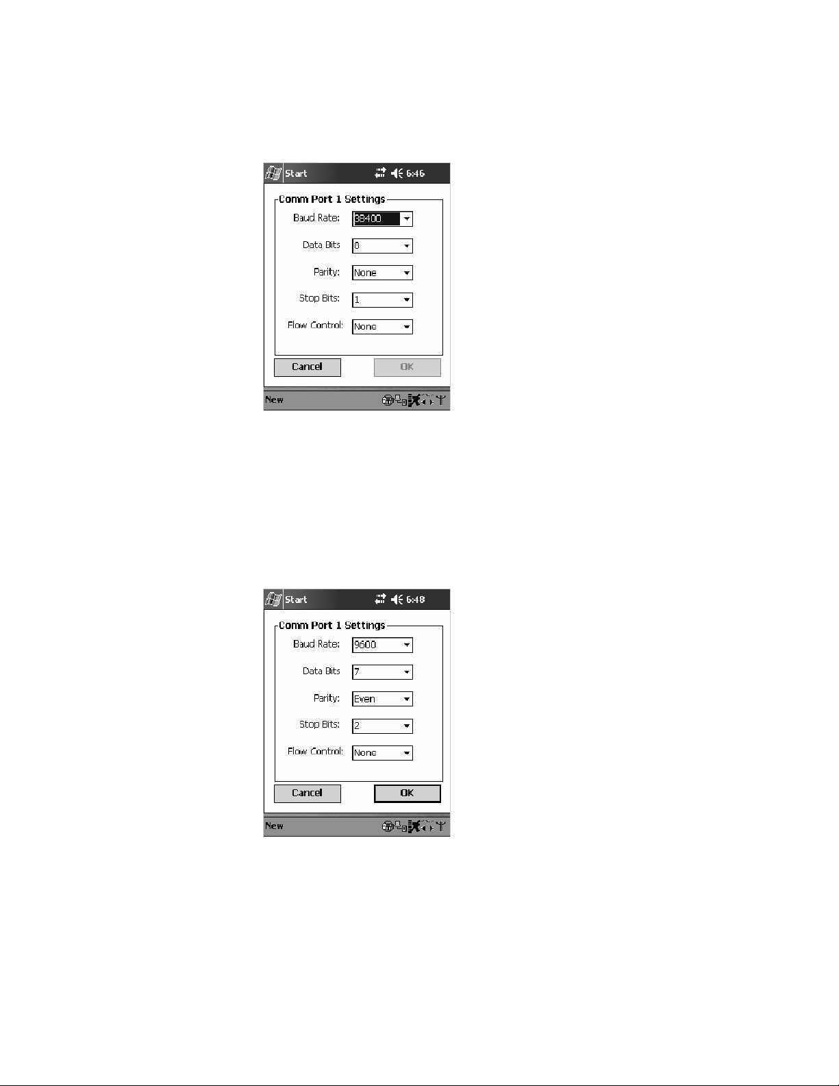
Changing Comm Settings
Tap Change Comm Settings to configure the settings for the COM1
port. Current settings are restored after a warm-boot is performed, but are
lost after a cold-boot is performed. When these settings are not changed,
the OK button is disabled (grayed out). When changes are made, tap OK
after it is enabled to accept these changes.
S Baud Rate: 1200, 2400, 4800, 9600, 19200, 38400, 57600,
115200
S Data Bits:7or8
S Parity: None, Odd, Even, Mark, Space
S Stop Bits:1or2
S Flow Control: None or Hardware
205700 Series Color Mobile Computer User’s Manual
Page 8
Scanner SupportChapter —6
Tethered Scanner
Default settings for the Tethered Scanner are shown in this illustration:
Sabre 1551E or 1553 Tethered Scanner
The default communication configuration for the Sabre 1551E or 1553
Tethered Scanner is shown in the following illustration. Scan the EasySet
Reset Factory Defaults label to set the Sabre 1551E or 1553 tethered scanner communications settings to this configuration. The COM1 port configuration settings must also match those of the scanner to scan labels.
Welch Allyn 1470 Imager Settings
You can set the Welch Allyn 1470 Imager to this configuration by scanning the Factory Default Settings label.
206 700 Series Color Mobile Computer User’s Manual
Page 9

6 Scanner Support—Chapter
Scanner Cabling
A null modem cable is required for the Welch Allyn 1470 Imager to communicate with the 700 Color Computer when using the 700 Color Serial
Cable (P/N: 226-999-001).
Sabre 1551E / 1553 Cables connect directly to the Model 700 COM Port.
Limitations and Capabilities
The Tethered Scanner has the following limitations:
S No auto detection of a scanner’s physical connection to COM1 port.
User needs to ensure the communication settings of COM1 port
matched the settings of the device.
S The Pocket PC Pocket Office applications misbehave when control
characters such as carriage return are wedged. This is a known Pocket
PC problem, which is being worked with Microsoft and f or which a
work around is being developed.
S Communications port is COM1 and cannot be changed.
S A complete bar code label is detected when the time between bytes (the
inter-byte gap) exceeds 100 ms. This allows that data could be concatenated if two labels were received while the Comm Port Wedge or the
1551/1553 Tethered Scanner was not performing a read. That is, it
could be wedging data just read or the read thread could be preempted.
Also, the labels could appear concatenated if the scanner itself were to
buffer the labels before transmitting them.
When enabled, the “Comm Port Wedge” menu option has this limitation:
S ThereisnobarcodeAPItogetbarcodedatafromthebarcodescan-
ner. The Comm Port Wedge transmits the data through the keyboard
interface only.
When enabled, the “1551/1553” menu option has these capabilities:
S Grid Data Editing is available.
S The source of the symbology configurations is only available via the
Easy Set command labels. You can only configure the Virtual Wedge
configurations via the Data Collection control panel applet Virtual
Wedge page. See Appendix A, “Configurable Settings,” for information.
S May transmit the data through the keyboard interface (via the Virtual
Wedge).
207700 Series Color Mobile Computer User’s Manual
Page 10

Scanner SupportChapter —6
S The bar code APIs, defined in the IADC interface, are available to get
barcodedatafromthebarcodescanner.Thefollowingexampleshows
how to programmatically collects bar code data:
#include “IADC.h” // Linked with ITCUUID.LIB
#include “ITCAdcMgmt.h” // Linked with ITCAdcDevMgmt.lib
IADC* pIADC;
HRESULT hrStatus = S_OK;
// Create a ADC COM interface to collect bar code data from the 1551E/1553
// when the 1551/1553 menu option is enabled.
hrStatus =
ITCDeviceOpen(TEXT(“ExtScanner”), // Name of the ADC device.
IID_IADC, // COM interface to return
ITC_DHDEVFLAG_READAHEAD, // Device’s Flags
(LPVOID *) &pIADC); // the returned interface
if( SUCCEEDED(hrStatus) )
{
BYTE byteBuffer[MAX_LABEL_SIZE];
DWORD dwLength = 0;
HRESULT hr = pIDC->Read(
byteBuffer, // Buffer to put the ADC data.
MAX_LABEL_SIZE, // Size of pDataBuffer in bytes.
&dwLength, // Number bytes returned.
NULL, // Time stamp of the received data. NULL.
INFINITE // Number of milliseconds to wait.
);
}
when done using this COM interface, delete it:
ITCDeviceClose( (IUnknown **) pIADC);
208 700 Series Color Mobile Computer User’s Manual
Page 11
For Unit s With PSM Build 3.00 or Newer
Configuring the Tethered Scanner
Do the following before you configure your tethered scanner from the Intermec Settings control panel applet. Information about the settings you
can configure with this applet is described in the Intermec Computer Com-
mand Reference Manual. The online manual is available from the Intermec
web site at www. intermec.com.
1 Connect your tethered scanner to the tethered scanner port.
2 From the 700 Color Computer, tap Start > Settings >theSystem tab >
the Intermec Settings icon.
6 Scanner Support—Chapter
3 Tap the Scanners, Symbologies option, then tap (+) to expand Dock
Tethered Scanner.
209700 Series Color Mobile Computer User’s Manual
Page 12
Scanner SupportChapter —6
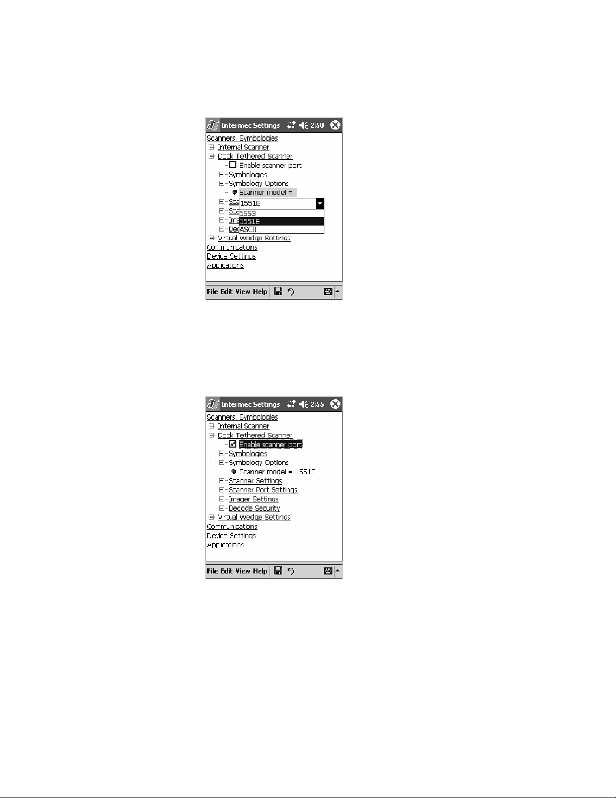
4 Tap Scanner model for a drop-down list, then select the applicable
scanner, such as “1551E” or “1553” in this sample screen.
5 Make sure a scanner is connected to your 700 Computer properly.
Then, tap to check Enable scanner port,thentapFile > Save Settings
from the bottom of the screen. These changes take several moments to
reset.
210 700 Series Color Mobile Computer User’s Manual
Page 13
6 Scanner Support—Chapter
1551E or 1553 Selected for Scanner Model
When “1551E” or “1553” is selected from the Scanner model option (see
step 4 above), and the port state is already enabled (see step 5),theprocess
will take several moments to reset. When 1551E or 1553 is successfully
connected during this step, the unit will emit some beeps. Here, the terminal is initializing the scanner at 9600 for the baud rate, 7 data bits, even
parity, and 2 stop bits and synchronizing the terminal’s configuration with
the attached scanner.
With “1551E” or “1553” selected, Symbologies, Symbology Options,
Hardware Trigger, and Scanner Port settings are configured from the Intermec Settings applet. See the the Intermec Computer Command Reference
Manual, available from the Intermec web site at www.intermec.com, for
more information about each enabled option.
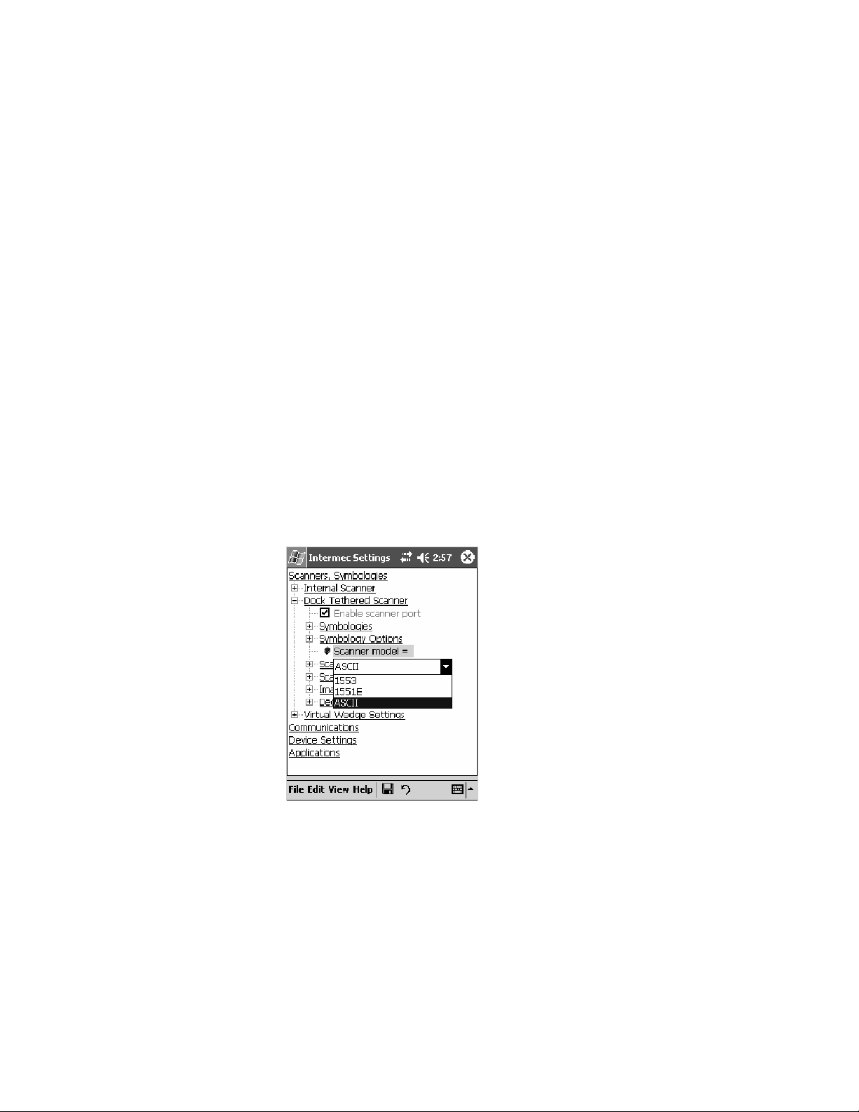
ASCII Selected for Scanner Model
To send data coming into the 700 Color Computer through the COM1
port from an external input device, as keyboard data to an application on
the desktop, do the following:
1 Select “ASCII” from the Scanner model option.
2 Tap to check Enable scanner port.
3 Tap File > Save Settings from the bottom of the screen.
With “ASCII” selected, Symbology Options, Hardware Trigger, and Scanner Port settings are configured from the Intermec Settings applet. See the
the Intermec Computer Command Reference Manual,availablefromtheIntermec web site at www.intermec.com, for more information about each
enabled option.
211700 Series Color Mobile Computer User’s Manual
Page 14

Scanner SupportChapter —6
Note: When selecting either the 1551E or the 1553 Scanner or enabling
the scanner port for these scanners, the 700 Computer tries to communicate with the attached scanner. If the scanner is not powered, if the cable is
not connected properly, the wrong cable is used, or if the scanner firmware
is older than 2.0, and the “Failed to save one or more settings” message
appears, then this step failed.
This process can take time as the terminal is going through a group of
RS-232 settings to communicate with the scanner. After successful communicated with the scanner (about eight beeps are generated), it initializes
the scanner with the 700 Computer’s current settings. This process might
generate a series of beeps pending on the firmware version installed in the
scanner. These beeps are suppressed in f irmware versions 2.08 or greater.
Troubleshootingthe 1551E/1553 Tethered Scanner
Do the following to troubleshoot your 1551/1553 Tethered Scanner:
1 Ensure the correct cable is used for the scanner on the tethered scanner
port. Note the 700 Computer cannot supply power to the scanner.
2 Perform a quick test to determine whether the connection is good.
Temporary select the scanner model as “ASCII,” then enable the scanner port state. Go to a command prompt or a notepad and scan a data
label. If a label is wedged into the command prompt or notepad, then
the connection is good.
3 If step 2 passes, reset the scanner configurations to their defaults (scan
the Reset Factory Defaults label on the next page) to prevent miscommunication, then reenable the scanner port state.
4 If step 2 fails, then the firmware installed in the tethered scanner may be
older than version 2.0. Upgrade your scanner firmware.
Reset Factory Defaults
Scan the EasySet software bar code label “Reset Factory Default” to restore
all of your scanner’s configurations to their factory defaults. When this
command label is scanned, reinitialize the tethered scanner (such as disable
the scanner port state, then enable it) on the 700 Computer. Otherwise,
the online configuration and scanning on the 700 Computer are not functional. In general, scan this label only to initially reset the scanner.
Do not scan EasySet command labels to change the following settings:
S Symbologies code mark S Code 128, EAN29 Identifier
S Preamble and Postamble S Enable/Disable symbologies
S Symbology ID transmit option
In some cases, scanning EasySet Command labels cause the current setting
on the user interface to be out of sync with the scanner settings. However,
in some cases, scanning these labels does corrupt scanned data.
The “Open COMx error: 0x00000037” message appears if the COM port
cannot open due to another application using the port. Disable that application to free up the COM1 port before you can enable the scanner. “x”
istheCOMportnumber,suchas1,2,or3.
212 700 Series Color Mobile Computer User’s Manual
Page 15

6 Scanner Support—Chapter
Tethered Scanner Supported Symbologies
The user interface may allow configuration of PDF417, Micro PDF417,
RSS, and Codablock bar code symbologies. However, these symbologies
are dependant on what scanner models and firmware versions are in use.
See the following table for a guideline and Appendix B, “Bar Code Symbol-
ogies” for more information on each supported symbology:
You can use a generic ASCII scanner with the 700 Color Computer.
Pending on the scanner, linear symbologies such as Code39, should decode correctly. However, 2D symbologies such as PDF417 may not decode correctly.
Symbologies 1551E 1553
Code39 XX
UPC/EAN X X
Code 128 XX
Interleaved 2 of 5 X X
Code 93 XX
Codabar X X
Code 2 of 5 XX
MSI X X
Plessey XX
Code 11 X X
Matrix 2 of 5 XX
Telepen X X
PDF417 Available in 1551 0808 PDF
Micro PDF417 Available in 1551 0808 PD F, Sxxp217_ or later
MaxiCode
Data Matrix
QR Code
RSS 14 F/w version 2.15 or later F/w version 2.15 or later
RSS Limited F/w version 2.15 or later F/w version 2.15 or later
RSS Expanded F/w version 2.15 or later F/w version 2.15 or later
Codablock A Available in 1551 0808 PDF
Codablock F Available in 1551 0808 PDF
UCC Composite
213700 Series Color Mobile Computer User’s Manual
Page 16

Scanner SupportChapter —6
214 700 Series Color Mobile Computer User’s Manual
Page 17

Programming
7
The following programming information pertains to the 700 Series Color
Mobile Computer:
S Creating CAB Files (page 216)
S Customization and Lockdown (page 233)
S FTP Server (page 234)
S Kernel I/O Control Functions (page 242)
S Network Selection APIs (page 258)
S Notifications (page 281)
S Reboot Functions (page 283)
S Remapping the Keypad (page 284)
Note: “700 Color” pertains to 740, 741, 750, 751, 760, and 761 Computers unless otherwise noted.
215700 Series Color Mobile Computer User’s Manual
Page 18

ProgrammingChapter —7
Creating CAB Files
The Windows CE operating system uses a .CAB file to install an application on a Windows CE-based device. A .CAB file is composed of multiple
files that are compressed into one file. Compressing multiple files into one
file provides the following benefits:
S All application files are present.
S A partial installation is prevented.
S The application can be installed from several sources, such as a desktop
computer or a Web site.
Use the CAB Wizard application (CABWIZ.EXE) to generate a .CAB file
foryourapplication.
Creating Device-Specific CAB Files
Do the following to create a device-specific .CAB file for an application, in
the order provided:
1 Create an .INF file with Windows CE-specific modifications (page
2 Optional Create a SETUP.DLL file to provide custom control of the
3 UsetheCABWizardtocreatethe.CABfile,usingthe.INFfile,the
Creating an .INF File
An .INF file specifies information about an application for the CAB Wizard. Below are the sections of an .INF file:
[Version]
This specifies the creator of the file, version, and other relevant information.
Required? Yes
S Signature:“signature_name”
S Provider:“INF_creator”
216).
installation process (page 228).
optional SETUP.DLL file, and the device-specific application files as
parameters (page 231).
“$Windows NT$”
The company name of the application, such as “Microsoft.”
S CESignature
“$Windows CE$”
Example
[Version]
Signature = “$Windows NT$”
Provider = “Intermec”
CESignature = “$Windows CE$”
216 700 Series Color Mobile Computer User’s Manual
Page 19

[CEStrings]
This specifies string substitutions f or the application name and the default
installation directory.
Required? Yes
S AppName: app_name
S InstallDir: default_install_dir
Example
[CEStrings]
AppName=“Game Pack”
InstallDir=%CE1%\%AppName%
[Strings]
This section is optional and defines one or more string keys. A string key
represents a string of printable characters.
Programming—Chapter 7
Name of the application. Other instances of %AppName% in the .INF
file are replaced with this string value, such as RP32.
Default installation directory on the device. Other instances of %InstallDir% in the .INF file are replaced with this string value. Example:
\SDMMC_Disk\%AppName%
Required? No
S string_key: value
Example
[Strings]
reg_path = Software\Intermec\My Test App
String consisting of letters, digits, or other printable characters. Enclose
value in double quotation marks ““”” if the corresponding string key is
used in an item that requires double quotation marks. No string_keys is
okay.
217700 Series Color Mobile Computer User’s Manual
Page 20

ProgrammingChapter —7
[CEDevice]
Describes the platform for the targeted application. All keys in this section
are optional. If a key is nonexistent or has no data, Windows CE does not
perform any checking with the exception being UnsupportedPlatforms.If
the UnsupportedPlatforms key exists but no data, the previous value is not
overridden.
Required? Yes
S ProcessorType : processor_type
S UnsupportedPlatforms: platform_family_name
The value that is returned by SYSTEMINFO.dwProcessorType.For
example, the value for the ARM CPU is 2577
This lists known unsupported platform family names. If the name
specified in the [CEDevice.xxx] section is different from that in the
[CEDevice] section, both platform_family_name values are unsupported
for the microprocessor specified by xxx. That is, the list of unsupported
platform family names is appended to the previous list of unsupported
names. Application Manager will not display the application for an
unsupported platform. Also, a user will be warned during the setup
process if the .CAB file is copied to an unsupported device.
Example
[CEDevice]
UnsupportedPlatforms = pltfrm1 ; pltfrm1 is unsupported
[CEDevice.SH3]
UnsupportedPlatforms = ; pltfrm1 is still unsupported
S VersionMin: minor_version
Numeric value returned by OSVERSIONINFO.dwVersionMinor. The
.CAB file is valid for the currently connected device if the version of
this device is greater than or equal to VersionMin.
S VersionMax: major_version
Numeric value returned by OSVERSIONINFO.dwVersionMajor. The
.CAB file is valid for the currently connected device if the version of
this device is less than or equal to VersionMax.
S BuildMin: build_number
Numeric value returned by OSVERSIONINFO.dwBuildNumber. The
.CAB file is valid for the currently connected device if the version of
this device is greater than or equal to BuildMin.
S BuildMax: build_number
Numeric value returned by OSVERSIONINFO.dwBuildNumber. The
.CAB file is valid for the currently connected device if the version of
this device is less than or equal to BuildMax.
218 700 Series Color Mobile Computer User’s Manual
Page 21

Programming—Chapter 7
Example
The following code example shows three [CEDevice] sections: one that
gives basic information for any CPU and two that are specific to the SH3
and the MIPS microprocessors.
[CEDevice] ; A “template” for all platforms
UnsupportedPlatforms = pltfrm1 ; Does not support pltfrm1
; The following specifies version 1.0 devices only.
VersionMin = 1.0
VersionMax = 1.0
[CEDevice.ARM] ; Inherits all [CEDevice] settings
; This will create a .CAB file specific to ARM devices.
ProcessorType = 2577 ; ARM .cab file is valid for ARM microprocessors.
UnsupportedPlatforms = ; pltfrm1 is still unsupported
; The following overrides the version settings so that no version checking is
performed.
VersionMin =
VersionMax =
[CEDevice.MIPS] ; Inherits all [CEDevice] settings
; This will create a .CAB file specific to “MIPS” devices.
ProcessorType = 4000 ; MIPS .CAB file is valid for MIPS
microprocessor.
UnsupportedPlatforms =pltfrm2 ; pltfrm1, pltfrm2 unsupported for MIPs .CAB
file.
Note:TocreatethetwoCPU-specific.CABfilesfortheSETUP.INFfile
in the previous example, run the CAB Wizard with the “/cpu arm mips”
parameter.
219700 Series Color Mobile Computer User’s Manual
Page 22

ProgrammingChapter —7
[DefaultInstall]
This describes the default installation of your application. Note that under
this section, you will list items expanded upon later in this description.
Required? Yes
S Copyfiles: copyfile_list_section
S AddReg: add_registry_section
S CEShortcuts: shortcut_list_section
S CESetupDLL: setup_DLL
Maps to files defined later in the .INF file, such as Files.App, Files.Font,
and Files.Bitmaps.
Example: RegSettings.All
String that identifies one more section that defines shortcuts to a file, as
defined in the [CEShortcuts] section.
Optimal string that specifies a SETUP.DLL file. It is written by the Independent Software Vendor (ISV) and contains customized functions
for operations during installation and removal of the application. The
file must be specified in the [SourceDisksFiles] section.
S CESelfRegister: self_reg_DLL_filename
Example
[DefaultInstall]
AddReg = RegSettings.All
CEShortcuts = Shortcuts.All
[SourceDiskNames]
This section describes the name and path of the disk on which your application resides.
Required? Yes
S disk_ordinal: disk_label,,path
S CESignature: “$Windows CE$”
String that identifies files that self-register by exporting the DllRegisterServer and DllUnregisterServer Component Object Model (COM)
functions. Specify these files in the [SourceDiskFiles] section. During
installation, if installation on the device fails to call the file’s exported
DllRegisterServer function, the file’s exported DllUnregisterServer
function will not be called during removal.
1=,“App files” , C:\Appsoft\RP32\...
2=,“Font files”,,C:\RpTools\...
3=,“CE Tools” ,,C:\windows ce tools...
Example
[SourceDisksNames] ; Required section
1 = ,“Common files”,,C:\app\common ; Using an absolute path
[SourceDisksNames.SH3]
2 = ,“SH3 files”,,sh3 ; Using a relative path
[SourceDisksNames.MIPS]
2 = ,“MIPS files”,,mips ; Using a relative path
220 700 Series Color Mobile Computer User’s Manual
Page 23

Programming—Chapter 7
[SourceDiskFiles]
This describes the name and path of the files in which your application
resides.
Required? Yes
S filename: disk_number[,subdir]
RPM.EXE = 1,c:\appsoft\...
WCESTART.INI = 1
RPMCE212.INI = 1
TAHOMA.TTF = 2
Note: [,subdir] is relative to the location of the INF file.
Example
[SourceDisksFiles] ; Required section
begin.wav = 1
end.wav = 1
sample.hlp = 1
[SourceDisksFiles.SH3]
sample.exe = 2 ; Uses the SourceDisksNames.SH3 identification of 2.
[SourceDisksFiles.MIPS]
sample.exe = 2 ; Uses the SourceDisksNames.MIPS identification of 2.
221700 Series Color Mobile Computer User’s Manual
Page 24

ProgrammingChapter —7
[DestinationDirs]
This describes the names and paths of the destination directories for the
application on the target device. Note Windows CE does not support directo-
ry identifiers.
Required? Yes
S file_list_section: 0,subdir
String that identifies the destination directory. The following list shows
the string substitutions supported by Windows CE. Use these only for
the beginning of the path. \
%CE1% \Program Files
%CE2% \Windows
%CE3% \My Documents
%CE4% \Windows\Startup
%CE5% \My Documents
%CE6% \Program Files\Accessories
%CE7% \Program Files\Communication
%CE8% \Program Files\Games
%CE9% \Program Files\Pocket Outlook
%CE10% \Program Files\Office
%CE11% \Windows\Start Menu\Programs
%CE12% \Windows\Start Menu\Programs\Accessories
%CE13% \Windows\Start Menu\Programs\Communications
%CE14% \Windows\Start Menu\Programs\Games
%CE15% \Windows\Fonts
%CE16% \Windows\Recent
%CE17% \Windows\Start Menu
%InstallDir%
Contains the path to the target directory selected during installation. It
is declared in the [CEStrings] section
%AppName%
Contains the application name defined in the [CEStrings] section.
Example
[DestinationDirs]
Files.Common = 0,%CE1%\My Subdir ; \Program Files\My Subdir
Files.Shared = 0,%CE2% ; \Windows
222 700 Series Color Mobile Computer User’s Manual
Page 25

Programming—Chapter 7
[CopyFiles]
This section, under the [DefaultInstall] section, describes the default files
to copy to the target device. Within the [DefaultInstall] section, files were
listed that must be defined elsewhere in the INF file. This section identifies that mapping and may contain flags.
Required? Yes
S copyfile_list_section: destination_filename,[source_filename]
The source_filename parameter is optional if it is the same as destina-
tion_filename.
S copyfile_list_section: flags
Thenumericvaluethatspecifiesanactiontobedonewhilecopyingfiles. The following table shows values supported by Windows CE.
Flag Value Description
COPYFLG_WARN_IF_SKIP 0x00000001 Warn user if skipping a file is attempted after error.
COPYFLG_NOSKIP 0x00000002 Do not allow a user to skip copying a file.
COPYFLG_NO_OVERWRITE 0x00000010 Do not overwrite files in destination directory.
COPYFLG_REPLACEONLY 0x00000400 Copy the source file to the destination directory only if the
file is already in the destination directory.
CE_COPYFLG_NO_DATE_DIALOG 0x20000000 Do not copy files if the target file is newer.
CE_COPYFLG_NODATECHECK 0x40000000 Ignore date while overwriting the target file.
CE_COPYFLG_SHARED 0x80000000 Create a reference when a shared DLL is counted.
Example
[DefaultInstall.SH3]
CopyFiles = Files.Common, Files.SH3
[DefaultInstall.MIPS]
CopyFiles = Files.Common, Files.MIPS
223700 Series Color Mobile Computer User’s Manual
Page 26

ProgrammingChapter —7
[AddReg]
This section, under the [DefaultInstall] section, is optional and describes
the keys and values that the .CAB file adds to the device registry. Within
the [DefaultInstall] section, a reference may have been made to this
section, such as “AddReg=RegSettings.All”. This section defines the
options for that setting.
Required? No
S add_registry_section: registry_root_string
S add_registry_section: value_name
S add_registry_section: flags
String that specifies the registry root location. The following list shows
thevaluessupportedbyWindowsCE.
S HKCR Same as HKEY_CLASSES_ROOT
S HKCU Same as HKEY_CURRENT_USER
S HKLM Same as HKEY_LOCAL_MACHINE
Registryvaluename.Ifempty,the“default”registryvaluenameisused.
Numeric value that specifies information about the registry key. The
following table shows the values that are supported by Window CE.
Flag Value Description
FLG_ADDREG_NOCLOBBER 0x00000002 If th e registry key exists, do not overwrite it. Can be used
with any of the other flags in this table.
FLG_ADDREG_TYPE_SZ 0x00000000 REG_SZ registry data type.
FLG_ADDREG_TYPE_MULTI_SZ 0x00010000 REG_MULTI_SZ registry data type. Value field that follows
can be a list of strings separated by commas.
FLG_ADDREG_TYPE_BINARY 0x00000001 REG_BINARY registry data type. Value field that follows
must be a list of numeric values separated by commas, one
byte per field, and must not use the 0x hexadecimal prefix.
FLG_ADDREG_TYPE_DWORD 0x00010001 REG_DWORD data type. The noncompatible format in the
Win32 Setup .INF documentation is supported.
Example
AddReg = RegSettings.All
[RegSettings.All]
HKLM,%reg_path%,,0x00000000,alpha ; <default> = “alpha”
HKLM,%reg_path%,test,0x00010001,3 ; Test = 3
HKLM,%reg_path%\new,another,0x00010001,6 ; New\another = 6
224 700 Series Color Mobile Computer User’s Manual
Page 27

[CEShortCuts]
This section, a Windows CE-specific section under the [DefaultInstall]
section, is optional and describes the shortcuts that the installation application creates on the device. Within the [DefaultInstall] section, a reference
may have been made to this section, such as “ShortCuts.All”. This section
defines the options for that setting.
Required? No
S shortcut_list_section: shortcut_filename
S shortcut_list_section: shortcut_type_flag
S shortcut_list_section: target_file_path
Programming—Chapter 7
String that identifies the shortcut name. It does not require the .LNK
extension.
Numeric value. Zero or empty represents a shortcut to a file; any nonzero numeric value represents a shortcut to a folder.
String value that specifies the destination location. Use the target file
name for a file, such as MyApp.exe, that must be defined in a file copy
list. For a path, use a file_list_section name defined in the [Destination-
Dirs] section, such as DefaultDestDir,orthe%InstallDir% string.
S shortcut_list_section: standard_destination_path
Optional string value. A standard %CEx% path or %InstallDir%.Ifno
value is specified, the shortcut_list_section name of the current section or
the DefaultDestDir value from the [DestinationDirs] section is used.
Example
CEShortcuts = Shortcuts.All
[Shortcuts.All]
Sample App,0,sample.exe ; Uses the path in DestinationDirs. Sample
App,0,sample.exe,%InstallDir% ; The path is explicitly specified.
Sample .INF File
[Version] ; Required section
Signature = “$Windows NT$”
Provider = “Intermec Technologies Corporation”
CESignature = “$Windows CE$”
;[CEDevice]
;ProcessorType =
[DefaultInstall] ; Required section
CopyFiles = Files.App, Files.Fonts, Files.BitMaps, Files.Intl,
Files.TelecomNcsCE, Files.Windows, Files.Import, Files.Export, Files.Work,
Files.Database, Files.WinCE AddReg = RegSettings.All ;CEShortcuts =
Shortcuts.All
[SourceDisksNames] ; Required section
1 = ,“App files” ,,c:\appsoft\...
2 = ,”Font files” ,,c:\WinNT\Fonts
3 = ,”CE Tools” ,,c:\windows ce tools\wce400\700ie\mfc\lib\x86
[SourceDisksFiles] ; Required section
rpm.exe = 1,C:\Appsoft\program\wce400\WCEX86Rel700
wcestart.ini = 1
225700 Series Color Mobile Computer User’s Manual
Page 28

ProgrammingChapter —7
rpmce212.ini = 1
intermec.bmp = 1
rpmlogo.bmp = 1
rpmname.bmp = 1
import.bmp = 1
export.bmp = 1
clock.bmp = 1
printer.bmp = 1
filecopy.bmp = 1
readme.txt = 1
lang_eng.bin = 1
rpmdata.dbd = 1,database\wce1
tahoma.ttf = 2
mfcce212.dll = 3
olece212.dll = 3
olece211.dll = 1,c:\windows ce tools\wce400\NMSD61102.11\mfc\lib\x86
rdm45wce.dll = 1,c:\rptools\rdm45wce\4_50\lib\wce400\wcex86rel
picfmt.dll = 1,c:\rptools\picfmt\1_00\wce400\wcex86rel6110
fmtctrl.dll = 1,c:\rptools\fmtctrl\1_00\wce400\wcex86rel6110
ugrid.dll = 1,c:\rptools\ugrid\1_00\wce400\wcex86rel6110
simple.dll = 1,c:\rptools\pspbm0c\1_00\wce400\wcex86rel
psink.dll = 1,c:\rptools\psink\1_00\wce400\WCEX86RelMinDependency
pslpwce.dll =1,c:\rptools\pslpm0c\1_00\wce400\WCEX86RelMinDependency
npcpport.dll = 1,c:\rptools\cedk\212_03\installable drivers\printer\npcp
;dexcom.dll = 1,c:\rptools\psdxm0c\1_00\x86
ncsce.exe = 1,c:\rptools\ncsce\1_04
nrinet.dll = 1,c:\rptools\ncsce\1_04
[DestinationDirs] ; Required section
;Shortcuts.All = 0,%CE3% ; \Windows\Desktop
Files.App = 0,%InstallDir%
Files.DataBase = 0,%InstallDir%\DataBase
Files.BitMaps = 0,%InstallDir%\Bitmaps
Files.Fonts = 0,%InstallDir%\Fonts
Files.Intl = 0,%InstallDir%\Intl
Files.TelecomNcsCE = 0,%InstallDir%\Telecom\NcsCE
Files.Windows = 0,%InstallDir%\Windows
Files.Import = 0,%InstallDir%\Import
Files.Export = 0,%InstallDir%\Export
Files.Work = 0,%InstallDir%\Work
Files.WinCE = 0,\storage_card\wince
[CEStrings] ; Required section
AppName = Rp32
InstallDir = \storage_card\%AppName%
[Strings] ; Optional section
;[Shortcuts.All]
;Sample App,0,sample.exe ; Uses the path in DestinationDirs.
;Sample App,0,sample.exe,%InstallDir% ; The path is explicitly specified.
[Files.App]
rpm.exe,,,0
rpm.ini,rpmce212.ini,,0
mfcce212.dll,,,0
olece212.dll,,,0
olece211.dll,,,0
rdm45wce.dll,,,0
picfmt.dll,,,0
226 700 Series Color Mobile Computer User’s Manual
Page 29

fmtctrl.dll,,,0
ugrid.dll,,,0
simple.dll,,,0
psink.dll,,,0
pslpwce.dll,,,0
npcpport.dll,,,0
;dexcom.dll,,,0
[Files.DataBase]
rpmdata.dbd,,,0
[Files.Fonts]
tahoma.ttf,,,0
[Files.BitMaps]
intermec.bmp,,,0
rpmlogo.bmp,,,0
rpmname.bmp,,,0
import.bmp,,,0
export.bmp,,,0
clock.bmp,,,0
printer.bmp,,,0
filecopy.bmp,,,0
Programming—Chapter 7
[Files.Intl]
lang_eng.bin,,,0
[Files.TelecomNcsCE]
ncsce.exe,,,0
nrinet.dll,,,0
[Files.Windows]
readme.txt,,,0
[Files.Import]
readme.txt,,,0
[Files.Export]
readme.txt,,,0
[Files.Work]
readme.txt,,,0
[Files.WinCE]
wcestart.ini,,,0
[RegSettings.All]
HKLM,”SOFTWARE\Microsoft\Shell\AutoHide”,,0x00010001,1
; Autohide the taskbar HKLM,”SOFTWARE\Microsoft\Shell\OnTop”,,0x00010001,0
; Shell is not on top
HKLM,”SOFTWARE\Microsoft\Clock”,SHOW_CLOCK,0x00010001,0
; Clock is not on taskbar
227700 Series Color Mobile Computer User’s Manual
Page 30

ProgrammingChapter —7
Using Installation Functions in SETUP.DLL
SETUP.DLL is an optional file that enables you to perform custom operations during installation and removal of your application. The following
list shows the functions that are exported by SETUP.DLL.
Install_Init Called be fore installation begins. Use this function to check the application version when reinstal-
ling an application and to determine if a dependent application is present.
Install_Exit Called after installation is complete. Use this function to handle errors that occur during applica-
tion installation.
Uninstall_Init Called before the removal process begins. Use this function to close the application, if the applica-
tion is running.
Uninstall_Exit Called after the removal process is complete. Use this function to save database information to a
file and delete the database and to tell the user where the user data files are stored and how to rein stall the application.
Note;Use[DefaultInstall] > CESelfRegister (page 220) in the .INF file to
point to SETUP.DLL.
After the CAB File Extraction
Cab files that need to cause a warm reset after cab extraction will need to
create the __RESETMEPLEASE__.TXT file in the “\Windows” directory.
The preferred method to create this file is within the DllMain portion of
theSETUP.DLLfile.Itlookslikethis:
#include <windows.h>
#include <Tlhelp32.h>
#include <winioctl.h>
#include <ce_setup.h> // in the public SDK dir
#define IOCTL_TERMINAL_RESET CTL_CODE (FILE_DEVICE_UNKNOWN,FILE_ANY_ACCESS,
2050, METHOD_NEITHER)
BOOL APIENTRY DllMain( HANDLE h, DWORD reason, LPVOID lpReserved )
{
return TRUE;
} // DllMain
//************************************************************************
// $DOCBEGIN$
// BOOL IsProcessRunning( TCHAR * pname );
//
// Description: Get process table snapshot, look for pname running.
//
// Arguments: pname - pointer to name of program to look for.
// for example, app.exe.
//
// Returns: TRUE - process is running.
// FALSE - process is not running.
// $DOCEND$
//************************************************************************
BOOL IsProcessRunning( TCHAR * pname )
{
HANDLE hProcList;
228 700 Series Color Mobile Computer User’s Manual
Page 31

PROCESSENTRY32 peProcess;
DWORD thDeviceProcessID;
TCHAR lpname[MAX_PATH];
if ( !pname || !*pname ) return FALSE;
_tcscpy( lpname, pname );
_tcslwr( lpname );
hProcList = CreateToolhelp32Snapshot( TH32CS_SNAPPROCESS, 0 );
if ( hProcList == INVALID_HANDLE_VALUE ) {
return FALSE;
} // end if
memset( &peProcess, 0, sizeof(peProcess) );
peProcess.dwSize = sizeof(peProcess);
if ( !Process32First( hProcList, &peProcess ) ) {
CloseToolhelp32Snapshot( hProcList );
return FALSE;
} // end if
Programming—Chapter 7
thDeviceProcessID = 0;
do {
_tcslwr( peProcess.szExeFile );
if ( _tcsstr( peProcess.szExeFile, lpname ) ) {
thDeviceProcessID = peProcess.th32ProcessID;
break;
} // end if
} while ( Process32Next( hProcList, &peProcess ) );
if ( ( GetLastError() == ERROR_NO_MORE_FILES ) && ( thDeviceProcessID == 0
)){
CloseToolhelp32Snapshot( hProcList );
return FALSE;
} // end if
CloseToolhelp32Snapshot( hProcList );
return TRUE;
} // IsProcessRunning
codeINSTALL_INIT Install_Init(
HWND hwndParent,
BOOL fFirstCall,
BOOL fPreviouslyInstalled,
LPCTSTR pszInstallDir )
{
return codeINSTALL_INIT_CONTINUE;
}
codeINSTALL_EXIT Install_Exit (
HWND hwndParent,
LPCTSTR pszInstallDir,
WORD cFailedDirs,
WORD cFailedFiles,
WORD cFailedRegKeys,
229700 Series Color Mobile Computer User’s Manual
Page 32

ProgrammingChapter —7
WORD cFailedRegVals,
WORD cFailedShortcuts )
{
HANDLE h;
TCHAR srcfile[MAX_PATH];
TCHAR dstfile[MAX_PATH];
if (cFailedDirs || cFailedFiles || cFailedRegKeys ||
cFailedRegVals || cFailedShortcuts)
return codeINSTALL_EXIT_UNINSTALL;
if ( IsProcessRunning( L”autocab.exe” ) )
{
h = CreateFile( L”\\Windows\\__resetmeplease__.txt”,
(GENERIC_READ | GENERIC_WRITE), 0, NULL, CREATE_ALWAYS,
FILE_ATTRIBUTE_HIDDEN, NULL );
if ( h != INVALID_HANDLE_VALUE )
CloseHandle( h );
else
{
// Couldn’t create the file. If it failed because the file already
exists, it is not fatal.
// Otherwise, notify user of the inability to reset the device and they
will have to
// perform it manually after all of the installations are complete.
} // end if
}
else
{
DWORD dret;
h = CreateFile( L”SYI1:”,
(GENERIC_WRITE | GENERIC_READ), 0, NULL, OPEN_EXISTING,
FILE_ATTRIBUTE_NORMAL, NULL );
// Force a warm start NOW.
if ( h != INVALID_HANDLE_VALUE )
{
DeviceIoControl( h, IOCTL_TERMINAL_RESET, NULL, 0, NULL, 0, &dret,
NULL);
// Won’t return, but we’ll show clean up anyway
CloseHandle( h );
}
else
{
// Couldn’t access SYSIO. Notify user.
} // end if
} // end if
return codeINSTALL_EXIT_DONE;
}
codeUNINSTALL_INIT
Uninstall_Init(
HWND hwndParent,
LPCTSTR pszInstallDir ) {
230 700 Series Color Mobile Computer User’s Manual
Page 33

Programming—Chapter 7
// TODO: Perform the reverse of INSTALL_INIT here
return codeUNINSTALL_INIT_CONTINUE;
}
codeUNINSTALL_EXIT
Uninstall_Exit(HWND hwndParent) {
// TODO: Perform the reverse of INSTALL_EXIT here
return codeUNINSTALL_EXIT_DONE;
}
The system software looks for the following directory structure and files on
theinstalledmediacardwhetheritbeanSDcardorCFcardorembedded
flash file system. No other folders need exist.
\2577\autorun.exe
\2577\autorun.dat
\2577\autocab.exe
\2577\autocab.dat
\cabfiles\*.cab
Creating CAB Files with CAB Wizard
After you create the .INF file and the optional SETUP.DLL file, use the
CAB Wizard to create the .CAB file. The command-line syntax for the
CABWizardisasfollows:
cabwiz.exe “inf_file” [/dest dest_directory] [/err error_file] [/cpu cpu_type
[cpu_type]]
A batch file, located in <program> directory, with the following commands, works well:
cabwiz.exe c:\appsoft\<program>\<inf_file_name>
cd \appsoft\<program>
“inf_file”
dest_directory The destination directory for the .CAB files. If no directory is specified, the . CAB files are created
error_file The file name for a log file that contains all warnings and errors that are encountered when the
cpu_type Creates a .CAB file for each specified microprocessor tag, which is a label used in the Win32 S E-
The SETUP.INF file path.
in the “inf_file” directory.
.CAB files are compiled. If no file name is specified, errors are displayed in message boxes. If a file
name is used, the CAB Wizard runs without the user interface (UI); this is useful for automated
builds.
TUP.INF file to differentiate between different microprocessor types. The /cpu parameter, followed by multiple cpu_type values, must be the last qualifier in the command line.
Example
This example creates .CAB files for the ARM and MIPS microprocessors,
assuming the Win32 SETUP.INF file contains the ARM and MIPS tags:
cabwiz.exe “c:\myfile.inf” /err myfile.err /cpu arm mips
Note: CABWIZ.EXE, MAKECAB.EXE, and CABWIZ.DDF (Windows
CE files available on the Windows CE Toolkit) must be installed in the
same directory on the desktop computer. Call CABWIZ.EXE using its full
path for the CAB Wizard application to run correctly.
231700 Series Color Mobile Computer User’s Manual
Page 34

ProgrammingChapter —7
Troubleshooting the CAB Wizard
To identify and avoid problems that might occur when using the CAB
Wizard, follow these guidelines:
S Use %% for a percent sign (%) character when using this character in
an .INF file string, as specified in Win32 documentation. This will not
work under the [Strings] section.
S Do not use .INF or .CAB files created for Windows CE to install ap-
plications on Windows-based desktop platforms.
S Ensure the MAKECAB.EXE and CABWIZ.DDF files, included with
Windows CE, are in the same directory as CABWIZ.EXE.
S Use the full path to call CABWIZ.EXE.
S Do not create a .CAB file with the MAKECAB.EXE file included with
Windows CE. You must use CABWIZ.EXE, which uses
MAKECAB.EXE to generate the .CAB files for Windows CE.
S Do not set the read-only attribute for .CAB files.
232 700 Series Color Mobile Computer User’s Manual
Page 35

Customization and Lockdown
Pocket PC (Windows Mobile) is a hardware specification created by
Microsoft Corporation. Devices that wish to carry the Pocket PC logo
must meet the minimum hardware requirements set in the Pocket PC specification. Manufacturers are free to add extra hardware functionality.
Pocket PC devices also use a specialized version of the CE operating system. This operating system is built from Windows CE 4.2 but contains
customizations, most notably the lack of a desktop and the addition of the
Today Screen.
To carry the Pocket PC logo, all devices must be tested at an Independent
Test Laboratory. The ITL testing is done based on Microsoft requirements. The test lab then reports the findings back to Microsoft Corporation and Intermec Technologies. If the 700 Color Computer passed all
tests, Intermec is allowed to ship the device with the Pocket PC logo. Each
time the operating system is modified, Intermec must resubmit to ITL
testing.
This means we cannot change the operating system much and still be a
Pocket PC device. For example, if we remove Word from the Start menu,
thedevicewouldfailITLtestingandwewouldnotbeabletoshipdevices
with the Pocket PC logo.
Although many customers want a Pocket PC device, some customers
would prefer that their users not have access to all of the Pocket PC features. Intermec cannot customize the operating system in any way but a custom application can:
Programming—Chapter 7
Delete items from the Start menu, and Programs folder. These items are just shortcuts in the file system so the application is not really being deleted. Cold booting the device will bring these items back so the application will need
toberunoneverycoldboot.
Use the RegFlushKey() API to save a copy of the registry to a storage device. See the 700 Color Management Tools
portion of the Intermec Developer’s Library CD for more information on how to do this. Saving a copy of the registry
restores most system settings in a cold boot situation.
Use the SHFullScreen() API in conjunction with other APIs to make the application take up the entire display and
prevent the start menu from being available.
Remap keys and disable keys on the keypad.
Create a custom SIP.
Make changes to the registry to configure the device.
Should you want your 700 Color Computer to display a full screen, keep
in mind that your computer is Pocket-PC certified by Microsoft Corporation. Check out resources on programming for the Pocket PC, using the
following links. These give full instructions on how to display full screen.
S Instructions on how to create a fu ll screen application for eVC++ ap-
plications using an SHFullScreen() API:
http://support.microsoft.com/support/kb/articles/Q266/2/44.ASP
S Instructions on how to create a fu ll screen application for eVB applica-
tions also using the SHFullScreen() API:
http://support.microsoft.com/support/kb/articles/Q265/4/51.ASP
233700 Series Color Mobile Computer User’s Manual
Page 36

ProgrammingChapter —7
FTP Server
FTP support is provided through the FTP Server application
FTPDCE.EXE (M S Windows CE Versions) which is provided as part the
base system.
FTPDCE is the Internet File Transfer Protocol (FTP) server process. The
server can be invoked from an application or command line. Besides servicing FTP client requests the FTP Server also send a “network announcement” to notify prospective clients of server availability.
Note: You should consult the RFC959 specification for proper use of
some of these commands at the following URL:
S http://www.ietf.org/rfc/rfc959.txt f or the text version, or
S http://www.w3.org/Protocols/rfc959/ for an html version
Do the following to send commands:
1 Start an FTP client and connect to the device FTP server.
2 Log in with “intermec” as the user name and “cr52401” for the pass-
word.
3 From the FTP client, send the command.
4 Wait for a response.
Synopsis
ftpdce [ options ]
Options
–Aaddr (where addr is in the form of a.b.c.d) Sets the single target address to which to send the network an-
nouncement. Default is broadcast.
–Bbyte Sets th e FTP data block size. Smaller sizes may be useful over slower links. Default is 65536.
–Cname Sets the device name. Used by Intermec management software.
–Fvalue Disables th e default Intermec account. A value of “0” disables the account. Default is “1”.
Note that disabling the default account without providing a working access control list on the server
will result in a device that will not accept any FTP connections.
–Hsec Sets the interval between network announcements in seconds.A value of “0” turns the network an-
nouncement off. Default is 30 seconds.
–Iaddr (where addr is in the form of a.b.c.d) Sets the preferred 6920 Communications Server (optional).
–Llog (where log is either “0” or “1”) Sets the state of logging. Default is 0 (disabled).
–Nsec Specifies the number of seconds to wait before initially starting FTP server services.
–Pport Sets the UDP port on which the network announcement will be sent. Default port is 52401.
–Qport Sets th e port on which the FTP Server will listen for connections. Defaultportis21.
–Rdir Sets the FTP mount point to this directory. Default is the root folder of the object store.
–Tscrip Sets the script name for the 6920 Communications Server to process.
–Uurl Sets the default URL for this device.
–Z“parms” Sets extended parameters to be included in the network announcement.
234 700 Series Color Mobile Computer User’s Manual
Page 37

Configurable Parameters Via the Registry Editor
The following parameters receive default values during the installation of
the Intermec FTP Server components. A few of the parameters are v isible
in the registry by default, but most must be created in order to modify the
default behavior of the FTP server.
BlockSize
Setting this parameter configures the Intermec FTP Server to transmit and
receive Ethernet packets using the specified data block size. By default, the
FTP server transmits and receives data using a 64K data block size. Adjusting this value may be useful in certain wireless TCP/IP installations.
Key HKLM\Software\Intermec\IFTP
Value Type REG_DWORD - data block size, in bytes.
Valid Range 0x100-0x10000 (256-65536 decimal).
Default 65536
DeviceName
This parameter configures the Intermec FTP Server to include the specified device name in the Intermec Device Network Announcement
(IDNA). Adjusting this value may be useful in assigning a symbolic name
to this device for asset tracking.
Programming—Chapter 7
Key HKLM\Software\Intermec\IFTP
Value Type REG_SZ
Valid Range None.
Default None.
DeviceURL
This parameter configures the Intermec FTP Server to transmit the specified URL in the IDNA. This can be used by Intermec management software for asset management.
Key HKLM\Software\Intermec\IFTP
Value Type REG_SZ
Valid Range None.
Default None.
235700 Series Color Mobile Computer User’s Manual
Page 38

ProgrammingChapter —7
IDNATarget
This parameter configures the Intermec FTP Server to transmit the IDNA
to a specific destination instead of a general UDP broadcast. This parameter is useful on networks that do not allow UDP broadcasts to be routed
between subnets. The use of this parameter restricts the reception of the
IDNA to the target destination only.
Key HKLM\Software\Intermec\IFTP
Value Type REG_SZ
Valid Range None.
Default None.
ManifestName
This parameter configures the Intermec FTP Server to transmit the specified manifest name in the IDNA. This parameter is used by the Intermec
6920 Communications Server for communication transactions. See the
6920 Communications Server documentation for proper use of this parameter.
Key HKLM\Software\Intermec\IFTP
Value Type REG_SZ
Valid Range None.
Default iftp.ini
PauseAtStartup
This parameter configures the Intermec FTP Server to sleep for the specified number of seconds before making the FTP service available on the
device.
Key HKLM\Software\Intermec\IFTP
Value Type REG_DWORD - stored in seconds.
Valid Range None.
Default 0
Root
This parameter configures the Intermec FTP Server to set the root of the
FTP mount point to the specified value. Note that this must map to an ex-
isting directory or you will not be able to log into the FTP Server.
Key HKLM\Software\Intermec\IFTP
Value Type REG_SZ
Valid Range None.
Default \
236 700 Series Color Mobile Computer User’s Manual
Page 39

Programming—Chapter 7
Transferring Files Over TCP/IP Net works
The File Transfer Protocol (FTP) server transfers files over TCP/IP networks. The FTPDCE.EXE program is a version that does not display a
window, but can run in the background.
FTPDCE is the Internet File Transfer Protocol (FTP) server process. The
server can be invoked from an application or command line. Besides servicing FTP client requests, the FTP Server also sends a “network announcement” to notify prospective clients of server availability.
Remarks
The FTP Server currently supports the following FTP requests:
CDUP Changes to the parent directory of the current working directory.
CWD Changes working directory.
DELE Deletes a file.
HELP Gives help information.
LIST (This FTP request is the same as the ls -lgA command). Gives list files in a directory.
MKD Makes a directory.
MODE (AlwaysUsesBinary).Specifies data transfer mode.
NLST (Not supported) Givesanamelistoffilesindirectory(thisFTPrequestisthesameasthels command).
NOOP Does nothing.
PASS Specifies a password.
PWD Prints the current working directory.
QUIT Terminates session.
RETR Retrieves a file.
RMD Removes a directory.
RNFR Specifies rename-from file name.
RNTO Specifies rename-to file name.
STOR Stores a file.
SYST Shows the operating system type of server system.
TYPE (Binary transfers only.) Specifies th e data transfer type with the Type parameter.
USER Specifies us er name.
XCUP (Not Normally Used) Changes the parent directory of the current working directory.
XCWD (Not Normally Used) Changes the current directory.
XMKD (Not Normally Used) Creates a directory.
XPWD (Not Normally Used) Prints the current working directory.
XRMD (Not Normally Used) Removes a directory.
237700 Series Color Mobile Computer User’s Manual
Page 40

ProgrammingChapter —7
SITE
The following extended OEM commands are supported by the SITE request. For Microsoft FTP clients, you can se nd site c ommands by preceding the command with “quote” such as “quote site status .”
ATTRIB Gets or sets the attributes of a given file. (SITE ATTRIB)
Usage QUOTE SITE ATTRIB [+R | -R][+A | -A ][+S | -S][+H | -H][[path]
filename]
+ Sets an attribute .
– Clears an attribute.
R Read-only file attribute.
A Archive file attribute.
S System file attribute.
H Hidden file attribute.
To retrieve the attributes of a file, only specify the file. The server response will be:
200-AD SHRCEIX filename
If the flag exists in its position shown above, it is set. Also, in addition to the values
defined above, there is also defined:
C Compressed file attribute.
E Encrypted file attribute.
I INROM file attribute.
X XIPfileattribute(executeinROM,notshadowedinRAM).
BOOT Reboots the server OS. This will cause the system on which the server is executing to
reboot. The FTP Server will shut down cleanly before reboot. All client connections
will be terminated. Cold boot is default except for the PocketPC build in which the
default is warm boot. (SITE BOOT)
Usage: QUOTE SITE BOOT [WARM | COLD]
COPY Copies a file from one location to another. (SITE COPY)
Usage: QUOTE SITE COPY [source][destination]
Example: QUOTE SITE COPY ‘\Storage Card\one.dat’ ‘\Stor-
age Card\two.dat’
EXIT Exits the FTP Server. This command will shut down the FTP Server thus termina-
ting all client connections. (SITE EXIT)
Usage: QUOTE SITE EXIT
HELP Gives site command help information. (SITE HELP)
Usage: QUOTE SITE HELP [command]
KILL Terminates a running program. (S ITE KILL)
Usage: QUOTE SITE KILL [program | pid]
LOG Opens or closes the program log. (SITE LOG)
Usage: QUOTE SITE LOG [open [filename]| close]
PLIST Lists the running processes (SITE PLIST)
Usage: QUOTE SITE PLIST
RUN Starts a program running . If th e program to run has spaces in path or filename,
wrappingthenamewithsinglequotesisrequired.
Usage: QUOTE SITE RUN [program]
Example: QUOTE SITE RUN ‘\Storage Card\app.exe’
238 700 Series Color Mobile Computer User’s Manual
Page 41

Programming—Chapter 7
STATUS Returns the current settings of the FTP Serve r. MAC, serial number, model, IP ad-
dress, network announcement information as well as OS memory usage are returned.
(SITE STATUS)
Usage: QUOTE SITE STATUS
TIMEOUT Toggles idle timeout between 120 to 1200 seconds (2 to 20 minutes). If this time r
expires with no activity between the client and the s erver, the client connection will
be disconnected. If the optional seconds argument is supplied, the server will set the
connection timeout to the number of seconds specified. Default is 120 seconds or 2
minutes. (SITE TIMEOUT)
Usage: QUOTE SITE TIMEOUT [seconds]
EKEY Gives site command electronic key information. (SITE HELP)
Usage: QUOTE SITE EKEY [command]
EVAL Gives site command electronic value information. (SITE HELP)
Usage: QUOTE SITE EVAL [command]
GVAL Gives site command general value information. (SITE HELP)
Usage: QUOTE SITE GVAL [command]
PVAL Gives site command value information. (SITE HELP)
Usage: QUOTE SITE PVAL [command]
The remaining FTP requests specified in RFC 959 are recognized, but not
implemented.
The banner returned in the parenthetical portion of its greeting shows the
version number of the FTP Server as well as the MAC address, serial number and operating system of the machine hosting the server.
The FTP Server supports browsing from the latest Netscape and Microsoft
web browsers. Drag-and-drop capability is available using this environment.
The FTPDCMDS subdirectory contains commands to use from the web
browser.
S Click EXITME.BIN to execute a SITE EXIT command.
S Click REBOOTME.BIN to execute SITE BOOT command.
S Use the GET command on these files to have the FTP Server execute
these commands.
S Security:
A customer configurable access control list may be installed on the
700 Color Computer. This list will allow customers to restrict access
via the FTP Server to users they wish and is in addition to default
Intermec accounts that are disabled using the -F0 option at runtime.
The access control list i s named FTPDCE.TXT and is placed in the
same directory on the 700 Color Computer as the FTPDCE.EXE
server. The FTP Server encrypts this file to keep the information safe
from unauthorized users. This file is encrypted when the FTP Server
is started so a file that is placed onto the 700 Color Computer after
the FTP Server starts will require a restart of the FTP Server to take
effect.
239700 Series Color Mobile Computer User’s Manual
Page 42

ProgrammingChapter —7
The format of the FTPDCE.TXT is as follows:
FTPDCE:user1!passwd1<cr><lf>user2!passwd2<cr><lf>user3
!passwd3<cr><lf>...
Note: The user accounts and passwords are case sensitive.
Once the access control list is encrypted on the 700 Color Computer,
the FTP Server hides this file from users. Once an access control list
is installed on the 700 Color Computer, a new one is not accepted by
the FTP Server until the previous one is removed. Encrypted access
control lists are not portable between 700 Color Computers.
Stopping the FTP Server from Your Application
To allow application programmers the ability to programmatically shut
down the FTP Server, the FTP Server periodically tests to see if a named
event is signaled. The name for this event is “ITC_IFTP_STOP” (no
quotes).
For examples on how to use events, consult the Microsoft Developer Network Library at http://www.msdn.com. The MSDN Library is an essential
resource for developers using Microsoft tools, products, and technologies.
It contains a bounty of technical programming information, including
sample code, documentation, technical articles, and reference guides.
Autostart FTP
This automatically starts the FTP Server (FTPDCE.EXE) when the 700
Color Computer is powered on. This is provided with the NDISTRAY
program (the Network Driver Interface Specification tray application),
which displays the popup menu that currently allows you to load and unload the network drivers. Tap the antenna icon in the System Tray of the
Today screen (a sample antenna icon is circled below) for this pop-up menu.
240 700 Series Color Mobile Computer User’s Manual
Page 43

Programming—Chapter 7
The default is to start the FTP Server at boot time, unless the following
registry entry is defined and set to “0” which disables AutoFTP. “1” enablestheAutoFTP.TheentrycanbesetfromtheNDISTRAYpop-up
menu by selecting either AutoFTP On or AutoFTP Off.
HKEY_LOCAL_MACHINE\Software\Intermec\Ndistray\StartupIFTP
These new entries are located below the selections to load the network
drivers. If the StartupIFTP registry key is not defined, the FTP Server is
loaded by default, to provide “out-of-the-box” capability for customers
who want to begin loading files to the 700 Color Computer without any
prior configuration.
Note: If a network driver is unloaded using the NDISTRAY popup menu,
and the FTP Server is running, the FTP Server is stopped.
On a resume, if AutoFTP is enabled and the FTP Server is running, it is
stopped and restarted. NDISTRAY uses a helper application named RESETIFTP to implement the restart on resume feature.
To do an AutoFTP Installation Check:
1 Ensure the FTP Server is running “out-of-the-box” the first time.
2 Tap Start > Today to access the Today screen, then tap the antenna
icon in the System Tray to bring up the NDISTRAY pop-up menu.
Select AutoFTP Off to disable AutoFTP. Do a warm boot and confirm
the FTP Server is not running.
3 Tap Start > Today to access the Today screen, then tap the antenna
icon in the System Tray to bring up the NDISTRAY pop-up menu.
Select AutoFTP On to enable AutoFTP, reboot, confirm it is running.
4 Unload the network driver when the FTP Server is running and con-
firm that it is not running any more.
5 Load the FTP Server, establish a connection, then suspend and resume.
The server should still run, but the FTP connection to the client should
be dropped.
241700 Series Color Mobile Computer User’s Manual
Page 44

ProgrammingChapter —7
Kernel I/O Controls
This describes the KernelIoControl() functions available to application
programmers. Most C++ applications will need to prototype the function
as the following to avoid link and compile errors.
extern “C” BOOL KernelIoControl(DWORD dwIoControlCode, LPVOID lpInBuf, DWORD
nInBufSize, LPVOID lpOutBuf, DWORD nOutBufSize, LPDWORD lpBytesReturned);
IOCTL_HAL_GET_DEVICE_INFO
This IOCTL returns either the platform type or the OEMPLATFORM
namebasedonaninputvalue.
Syntax
BOOL KernelIoControl( IOCTL_HAL_GET_DEVICE_INFO, LPVOID
lpInBuf, DWORD nInBufSize, LPVOID lpOutBuf, DWORD
nOutBufSize, LPDWORD lpBytesReturned );
Parameters
lpInBuf Points to a DWORD containing either the SPI_GETPLAT-
FORMTYPE or SPI_GETOEMINFO value.
lpInBufSize Must be set to sizeof(DWORD).
lpOutBuf Must point to a buffer large enough to hold the return data of the
function. If SPI_GETPLATFORMTYPE is specified in lpInBuf,
then th e “PocketPC\0” Unicode string is returned. If SPI_GETOEMINFO is specified in lpInBuf, then the “Inter mec 700\0”
Unicode string is returned.
nOutBufSize ThesizeoflpOutBuf in bytes. Must be large enough to hold the
string returned.
lpBytesReturned The actual number of bytes returned by the function for the data
requested.
Return Values
Returns TRUE if function succeeds. Returns FALSE if the function fails.
GetLastError() may be used to get the extended error value.
242 700 Series Color Mobile Computer User’s Manual
Page 45

IOCTL_HAL_ITC_READ_PARM
Usage
#include “oemioctl.h”
Syntax
BOOL KernelIoControl( IOCTL_HAL_ITC_READ_PARM,LPVOID
lpInBuf,DWORD nInBufSize,LPVOID lpOutBuf,DWORD
nOutBufSize,LPDWORD lpBytesReturned );
Parameters
lpInBuf Points to this structure . See “ID Field Values”below.
nInBufSize Must be set to the size of the PARMS structure.
lpOutBuf Must point to a buffer large enough to hold the return data of the
nOutBufSize ThesizeoflpOutBuf in bytes.
lpBytesReturned Number of bytes returned by the function for the data requested.
Programming—Chapter 7
struct PARMS {
BYTE id;
BYTE ClassId;
};
function. If this field is s et to NULL and nOutBufSize is set to zero
when the function is called the function will return the number
bytes required by the buffer.
Return Values
Returns TRUE if function succeeds. Returns FALSE if the function fails.
GetLastError() may be used to get the error value. Either
ERROR_INVALID_PARAMETER or
ERROR_INSUFFICIENT_BUFFER may be returned when this function
is used to get the error.
ID Field Values
The id field of the PARMS structure may be one of the following values:
ID Field Values
ITC_NVPARM_ETHERNET_ID
This IOCTL returns the Ethernet 802.11b or 802.11b/g MAC Address. Six bytes are returned in the buffer pointed
to by the lpOutBuffer parameter.
ITC_NVPARM_SERIAL_NUM
This IOCTL returns the serial number of the device in BCD format. Six bytes are returned in the buffer pointed to
by the lpOutBuffer parameter.
ITC_NVPARM_MANF_DATE
This IOCTL returns the device date of manu facture in the BCD YYYY/MM/D D format. Four bytes are returned in
the buffer pointed to by the lpOutBuffer parameter.
ITC_NVPARM_SERVICE_DATE
This IOCTL returns the device’s date of last service in BCD YYYY/MM/DD format. Four bytes are returned in the
buffer pointed to by the lpOutBuffer parameter.
243700 Series Color Mobile Computer User’s Manual
Page 46

ProgrammingChapter —7
ID Field Values (continued)
ITC_NVPARM_DISPLAY_TYPE
This IOCTL returns the device’s display type. One byte is returned in the buffer pointed to by the lpOutBuffer
parameter.
ITC_NVPARM_EDG_IP
This IOCTL returns the device Ethernet debug IP address. Four bytes are returned in the buffer pointed to by the
lpOutBuffer parameter.
ITC_NVPARM_EDBG_SUBNET
This IOCTL returns the device Ethernet debug subnet mask. Four bytes are returned in the buffer pointed to by the
lpOutBuffer parameter.
ITC_NVPARM_ECN
This IOCTL returns ECNs applied to the device in a bit array format. Four bytes are returne d in the buffer pointed
to by the lpOutBuffer parameter.
ITC_NVPARM_CONTRAST
This IOCTL returns the device default contrast setting. Two bytes are returned in the buffer pointed to by the
lpOutBuffer parameter.
ITC_NVPARM_MCODE
This IOCTL returns the manufacturing configuration code for the device. Sixteen bytes are
returned in the buffer pointed to by the lpOutBuffer parameter.
ITC_NVPARM_VERSION_NUMBER
This IOCTL returns the firmware version for various system components. These values for the ClassId field of the
PARMS structure are allowed when ITC_NVPARM_VERSION_NUMBER is used in the id field:
S VN_CLASS_KBD Returns a five-byte s tring, including null terminator, that contains an ASCII value which
represents the keypad microprocessor version in the system. The format of the string is x.xx with a terminating null
character.
S VN_CLASS_ASIC Returns a five-byte s tring, including nu ll terminator, that contains an ASCII value which
represents the version of the FPGA firmware in the system. The format of the string is x.xx with a terminating null
character.
S VN_CLASS_BOOTSTRAP Returns a five-byte string, including null terminator, that contains an ASCII value
which represents the version of the Bootstrap Loader firmware in the system. The format of the string is x.xx with a
terminating null character.
ITC_NVPARM_INTERMEC_SOFTWARE_CONTENT
This IOCTL reads the manufacturing flag bits from the non-volatile data store that dictates certain software
parameters. A BOOLEAN DWORD is returned in the buffer pointed to by lpOutBuffer that indicates if Intermec
ContentisenabledintheXIPregions.TRUEindicatesthatitisenabled.FALSEindicatesthatitisnotenabled.
ITC_NVPARM_ANTENNA_DIVERSITY
This IOCTL reads the state of the antenna diversity flag. A BOOLEAN DWORD is returned in the buffer pointed
to by lpOutBuffer that indicates if there is a diversity antenna installed. TRUE indicates that it is installed. FALSE
indicatesthatitisnotinstalled.
ITC_NVPARM_WAN_RI
This IOCTL reads the state of the WAN ring indicator flag. A BOOLEAN DWORD is returned in the buffer
pointed to by lpOutBuffer that indicates t h e polarity of the WAN RI signal. TRUE indicates active high. FALSE
indicates active low.
244 700 Series Color Mobile Computer User’s Manual
Page 47

Programming—Chapter 7
ID Field Values (continued)
ITC_NVPARM_RTC_RESTORE
This IOCTL reads the state of the real-time clock restore flag. A BOOLEAN DWORD is returned in the buffer
pointed to by lpOutBuffer. TRUE indicates that the RTC is restored upon a cold boot. FALSE indicates that the
RTC is not restored.
ITC_NVPARM_INTERMEC_DATACOLLECTION_SW
This IOCTL reads the state of the data collection software enabled flag. A BOOLEAN D WORD is retu rned in the
buffer pointer to by lpOutBuffer that indicates the data collection software is to install at boot time. F ALSE indicates
the data collection software should not install.
ITC_NVPARM_INTERMEC_DATACOLLECTION_HW
This IOCTL reads the data collection hardware flags. A BYTE is returned in the buffer pointer to by lpOutBuffer
that indicates the type of data collection hardware installed. The maximum possible value returned is
ITC_DEVID_SCANHW_MAX.
S ITC_DEVID_SCANHW_NONE No scanner hardware is installed.
S ITC_DEVID_OEM2D_IMAGER OEM 2D imager is installed.
S ITC_DEVID_INTERMEC2D_IMAGER Intermec 2D imager is installed.
S ITC_DEVID_SE900_LASER SE900 laser is installed.
S ITC_DEVID_SE900HS_LASER SE900HS laser is installed.
S ITC_DEVID_INTERMEC_EVIO EVIO linear imager is installed.
The high bit indicates whether the S6 scanning engine is installed. The bit mask for this is
ITC_DEVID_S6ENGINE_MASK. A non-zero value indicates that th e S6 scanning engine is installed.
ITC_NVPARM_WAN_INSTALLED
This IOCTL reads the state of the WAN radio installed flag. A BOOLEAN DWORD is returned in the buffer
pointed to by lpOutBuffer. TRUE indicates that the WAN radio is installed. FALSE indicates that no WAN radio is
installed.
ITC_NVPARM_WAN_FREQUENCY
This IOCTL reads the state of the WAN radio frequency flag. A BOOLEAN DWORD is returned in the buffer
pointed to by lpOutBuffer. TRUE indicates that the WAN radio frequency is United States. FALSE indicates that
the WAN radio frequency is Eu ropean.
ITC_NVPARM_WAN_RADIOTYPE
This IOCTL reads the WAN radio ID installed by manufacturing. A BYTE is returned in the buffer pointer to by
lpOutBuffer whichindicatesthetypeofWANradiohardwareinstalled.Themaximumpossiblevaluereturnedis
ITC_DEVID_WANRADIO_MAX. The current definitions are:
S ITC_DEVID_WANRADIO_NONE No WAN radio installed.
S ITC_DEVID_WANRADIO_SIERRA_SB555 CDMA S i erra Wireless radio.
S ITC_DEVID_WANRADIO_XIRCOM_GEM3503 GSM/GPRS Intel (Xircom) radio.
S ITC_DEVID_WANRADIO_SIEMENS_MC45 GSM/GPRS Siemens radio.
S ITC_DEVID_WANRADIO_SIEMENS_MC46 GSM/GPRS Siemens radio.
ITC_NVPARM_80211_INSTALLED
This IOCTL reads the state of the 802.11b or 802.11b/g radio installed flag. A BOOLEAN DWORD is returned in
the buffer pointed to by lpOutBuffer. TRUE indicates that the 802.11b or 802.11b/g radio is installed. FALSE
indicates that no 802.11b or 802.11b/g radio is installed.
ITC_NVPARM_80211_RADIOTYPE
This IOCTL reads the 802. 11b or 802.11b/ g radio ID installed by manufacturing. A BYTE is returned in the buffer
pointer to by lpOutBuffer that indicates the type of 802.11b or 802.11b/g radio hardware installed. The maximum
possible value returned is ITC_DEVID_80211RADIO_MAX. The current definitions are:
S ITC_DEVID_80211RADIO_NONE No 802.11b or 802.11b/g radio installed.
S ITC_DEVID_80211RADIO_INTEL_2011B Inte l 2011B radio installed.
245700 Series Color Mobile Computer User’s Manual
Page 48

ProgrammingChapter —7
ID Field Values (continued)
ITC_NVPARM_BLUETOOTH_INSTALLED
This IOCTL reads the state of the Bluetooth radio installed flag. A BOOLEAN DWORD is returned in the buffer
pointed to by lpOutBuffer. T RUE indicates that the Bluetooth radio is installed. FALSE indicates that no Bluetooth
radio is installed.
ITC_NVPARM_SERIAL2_INSTALLED
This IOCTL reads the state of the serial 2 (COM2) device installed flag. A BOOLEAN D WORD is retu rne d in the
buffer pointed to by lpOutBuffer. TRUE indicates that the serial 2 device is installed. FALSE indicates that no serial
2 device is installed.
ITC_NVPARM_VIBRATE_INSTALLED
This IOCTL reads the state of the vibrate device installed flag. A BOOLEAN DWORD is returne d in the buffer
pointed to by lpOutBuffer. T RUE indicates that the vibrate device is ins talled. FALSE i ndicates that no vibrate
device is installed.
ITC_NVPARM_LAN9000_INSTALLED
This IOCTL reads the state of the Eth e rne t device ins talled flag. A BOOLEAN DWORD is returned in the buffer
pointed to by lpOutBuffer. TRUE indicates that the Ethernet device i s installed. FALSE indicates that no Ethernet
device is installed.
ITC_NVPARM_SIM_PROTECT_HW_INSTALLED
This IOCTL reads the state of the SIM card protection hardware installed flag. A BOOLEAN DWORD is returned
in the buffer pointed to by lpOutBuffer. TRUE indicates that the SIM card protection hardware is installed. FALSE
indicates that no SIM card protection hardware is installed.
ITC_NVPARM_SIM_PROTECT_SW_INSTALLED
This IOCTL reads the state of the SIM card protection software installed flag. A BOOLEAN DWORD is returned
in the buffer pointed to by lpOutBuffer. TRUE indicates that the SIM card protection software is installed. FALSE
indicates that no SIM card protection software is installed.
246 700 Series Color Mobile Computer User’s Manual
Page 49

IOCTL_HAL_ITC_WRITE_SYSPARM
Describes and enables the registry save location.
Usage
#include “oemioctl.h”
Syntax
BOOL KernelIoControl( IOCTL_HAL_ITC_WRITE_SYSPARM,LPVOID
lpInBuf,DWORD nInBufSize, LPVOID lpOutBuf, DWORD
nOutBufSize, LPDWORD lpBytesReturned );
Parameters
lpInBuf Asinglebytethatmaybeoneoftheid values. See “ID Field Values”
nInBufSize Must be set to the size of the lpInBuf in bytes.
lpOutBuf Must point to a buffer large enough to hold the data to be written
nOutBufSize ThesizeoflpOutBuf in bytes.
lpBytesReturned The number of bytes returned by the function.
Programming—Chapter 7
on the next page.
to the non-volatile data store.
Return Values
Returns TRUE if function succeeds. Returns FALSE if the function fails.
GetLastError() may be used to get the error value. Either
ERROR_INVALID_PARAMETER or
ERROR_INSUFFICIENT_BUFFER may be returned when this function
is used to get the error.
247700 Series Color Mobile Computer User’s Manual
Page 50

ProgrammingChapter —7
ID Field Values
The id field of lpInBuf may be one of the following values:
ID Field Values
ITC_REGISTRY_SAVE_ENABLE
This function enables or disables the save regis try to non-volatile media featu re of the RegFlushKey() function.
lpOutBuf mustbesettozero(FALSE)ifthefeatureistobedisabledorone(TRUE)ifthefeatureistobeenabled.
ITC_ DOCK_SWITCH
This IOCTL sets a position of the dock switch. The dock switch may be set to either “modem” or “serial” positions.
lpOutBuf must point to a buffer that contains a byte value of e ither DOCK_MODEM or DOCK_SERIAL as
defined in OEMIOCTL.H; the value specifies the position the switch is to be set. The call appears as follows:
// port = DOCK_MODEM or DOCK_SERIAL as defined in oemioctl.h
BOOL SetDockSwitch( BYTE port)
{
DWORD cmd = ITC_DOCK_SWITCH;
DWORD cbRet;
return KernelIoControl(IOCTL_HAL_ITC_WRITE_SYSPARM,&cmd, sizeof(cmd),
&port,sizeof(port),&cbRet)
}
ITC_ WAKEUP_MASK
This IOCTL sets a bit mask that represents the mask for the five programmable wakeup keys. The I/O key is not a
programmable wakeup key. By default it is always the system resume key and all other keys are set to disable key
wakeup. A zero in a bit position masks the wakeup for that key. A one in a bit position enables wakeup for that key.
lpOutBuf must point to a buffer that contains a byte value of a wakeup mask consisting of the OR’ed constants as
definedinOEMIOCTL.H.Onlythefollowingkeysareprogrammableaswakeupevents.
#define SCANNER_TRIGGER 1
#define SCANNER_LEFT 2
#define SCANNER_RIGHT 4
#define GOLD_A1 8
#define GOLD_A2 0x10
ITC_AMBIENT_KEYBOARD (does not apply to the 730 Computer)
This IOCTL sets the threshold for the keypad ambient sensor. This can be a value from 0 (always off) to 255 (always
on). lpOutBuf must point to a buffer that contains a byte value of the desired setting.
ITC_AMBIENT_FRONTLIGHT (does not apply to the 730 Computer)
This IOCTL sets the threshold for the frontlight ambient sensor. This can be a value from 0 (always off) to 255.
lpOutBuf must point to a buffer that contains a byte value of the desired setting.
248 700 Series Color Mobile Computer User’s Manual
Page 51

IOCTL_HAL_GET_DEVICEID
This IOCTL returns the device ID. There are two types of device IDs
supported,whicharedifferentiatedbasedonthesizeoftheoutput buffer.
TheUUIDisreturnedifthebuffersizeissetto
sizeof(UNIQUE_DEVICEID),otherwisetheoldstyledeviceIDisreturned.
Usage
#include “pkfuncs.h”
#include “deviceid.h”
Syntax
BOOL KernelIoControl( IOCTL_HAL_GET_DEVICEID,LPVOID
lpInBuf,DWORD nInBufSize,LPVOID lpOutBuf,DWORD
nOutBufSize,LPDWORD lpBytesReturned );
Parameters
lpInBuf Should be set to NULL. STRICT_ID settings are not supported.
lpInBufSize Should be set to zero.
lpOutBuf Must point to a UNIQUE_DEVICEID structure as defined by
nOutBufSize The size of the UNIQUE_DEVICEID in bytes if the UUID is to
lpBytesReturned The number of bytes returned by the function.
Programming—Chapter 7
DEVICEID.H if the UUID is to be returned
be returned. A DEVICE_ID as defined by PKFUNCS.H is returned if the size in bytes is greater than or equal to sizeof(DE-
VICE_ID).
Return Values
Returns TRUE if function succeeds. Returns FALSE if the function fails.
GetLastError() may be used to get the extended error value.
249700 Series Color Mobile Computer User’s Manual
Page 52

ProgrammingChapter —7
IOCTL_HAL_GET_OAL_VERINFO
Returns the HAL version information of the Pocket PC image.
Usage
#include “oemioctl.h”
Syntax
BOOL KernelIoControl( IOCTL_HAL_GET_OAL_VERINFO,LPVOID
lpInBuf,DWORD nInBufSize,LPVOID lpOutBuf,DWORD
nOutBufSize,LPDWORD lpBytesReturned );
Parameters
lpInBuf Should be set to NULL.
lpInBufSize Should be set to zero.
lpOutBuf Must point to a VERSIONINFO s tructure as defined by
nOutBufSize ThesizeofVERSIONINFOinbytes.
lpBytesReturned Returns sizeof(PVERSIONINFO).
OEMIOCTL.H. The fields should have these values:
S cboemverinfo sizeof (tagOemVerInfo);
S verinfover 1
S sig; “ITC\0”
S id; ‘N’
S tgtcustomer “”
S tgtplat SeaRay
S tgtplatversion Current build version number
S tgtcputype[8]; “Intel\0”
S tgtcpu “PXA255\0”;
S tgtcoreversion “”
S date Build time
S time Build date
Return Values
Returns TRUE if function succeeds. Returns FALSE if the function fails.
GetLastError() may be used to get the extended error value.
250 700 Series Color Mobile Computer User’s Manual
Page 53

IOCTL_HAL_GET_BOOTLOADER_VERINFO
Returns the HAL version information of the Pocket PC image.
Usage
#include “oemioctl.h”
Syntax
BOOL KernelIoControl( IOCTL_HAL_GET_OAL_VERINFO,LPVOID
lpInBuf, DWORD nInBufSize,LPVOID lpOutBuf,DWORD
nOutBufSize,LPDWORD lpBytesReturned );
Parameters
lpInBuf Should be set to NULL.
nInBufSize Should be set to zero.
lpOutBuf Must point to a VERSIONINFO s tructure as defined by
OEMIOCTL.H. The fields should have these values:
S cboemverinfo Sizeof (tagOemVerInfo);
S verinfover 1
S sig; “ITC\0”
S id; ‘B’
S tgtcustomer “”
S tgtplat SeaRay
S tgtplatversion Current build version number of the
S tgtcputype[8]; “Intel\0”;
S tgtcpu “PXA255\0”
S tgtcoreversion “”
S date Build time
S time Build date
nOutBufSize ThesizeofVERSIONINFOinbytes.
lpBytesReturned The number of bytes returned to lpOutBuf.
Programming—Chapter 7
bootstrap loader
Return Values
Returns TRUE if function succeeds. Returns FALSE if the function fails.
GetLastError() may be used to get the extended error value.
251700 Series Color Mobile Computer User’s Manual
Page 54

ProgrammingChapter —7
IOCTL_HAL_WARMBOOT
Causes the system to perform a warm-boot. The object store is retained.
Usage
#include “oemioctl.h”
Syntax
BOOL KernelIoControl( IOCTL_HAL_WARMBOOT,LPVOID
lpInBuf,DWORD nInBufSize,LPVOID lpOutBuf,DWORD
nOutBufSize,LPDWORD lpBytesReturned );
Parameters
lpInBuf Should be set to NULL.
lpInBufSize Should be set to zero.
lpOutBuf Should be NULL.
nOutBufSize Should be zero.
Return Values
None.
IOCTL_HAL_COLDBOOT
Causes the system to perform a cold-boot. The object store is cleared.
Usage
#include “oemioctl.h”
Syntax
BOOL KernelIoControl( IOCTL_HAL_COLDBOOT,LPVOID
lpInBuf,DWORD nInBufSize,LPVOID lpOutBuf,DWORD
nOutBufSize,LPDWORD lpBytesReturned );
Parameters
lpInBuf Should be set to NULL.
lpInBufSize Should be set to zero.
lpOutBuf Should be NULL.
nOutBufSize Should be zero.
Return Values
None.
252 700 Series Color Mobile Computer User’s Manual
Page 55

IOCTL_HAL_GET_RESET_INFO
This IOCTL code allows software to check the type of the most recent
reset.
Usage
#include “oemioctl.h”
Syntax
BOOL KernelIoControl( IOCTL_HAL_GET_RESET_INFO,LPVOID
lpInBuf,DWORD nInBufSize,LPVOID lpOutBuf,DWORD
nOutBufSize,LPDWORD lpBytesReturned );
Parameters
lpInBuf Should be set to NULL.
lpInBufSize Should be set to zero.
lpOutBuf Must point to a HAL_RESET_INFO structure. See sample below.
nOutBufSize ThesizeofHAL_RESET_INFOinbytes.
lpBytesReturned The number of bytes returned by the function.
Programming—Chapter 7
Return Values
Returns TRUE if function succeeds. Returns FALSE if the function fails.
GetLastError() may be used to get the extended error value.
Sample
typedef struct {
DWORD ResetReason; // most recent reset type
DWORD ObjectStoreState; // state of object store
} HAL_RESET_INFO, * PHAL_RESET_INFO;
// Reset reason types
#define HAL_RESET_TYPE_UNKNOWN 0
#define HAL_RESET_REASON_HARDWARE 1 // cold
#define HAL_RESET_REASON_SOFTWARE 2 // suspend
#define HAL_RESET_REASON_WATCHDOG 4
#define HAL_RESET_BATT_FAULT 8 // power fail
#define HAL_RESET_VDD_FAULT 16 // warm boot
// Object store state flags
#define HAL_OBJECT_STORE_STATE_UNKNOWN 0
#define HAL_OBJECT_STORE_STATE_CLEAR 1
253700 Series Color Mobile Computer User’s Manual
Page 56

ProgrammingChapter —7
IOCTL_HAL_GET_BOOT_DEVICE
This IOCTL code allows software to check which device CE booted from.
Usage
#include “oemioctl.h”
Syntax
BOOL KernelIoControl( IOCTL_HAL_GET_BOOT_DEVICE,LPVOID
lpInBuf,DWORD nInBufSize,LPVOID lpOutBuf,DWORD
nOutBufSize,LPDWORD lpBytesReturned );
Parameters
lpInBuf Should be set to NULL.
lpInBufSize Should be set to zero.
lpOutBuf Must point to a buffer large enough to hold a DWORD (4 bytes)
nOutBufSize ThesizeoflpOutBuf in bytes (4).
lpBytesReturned The number of bytes returned by the function.
that contains the boot device. The following boot devices are supported:
#define HAL_BOOT_DEVICE_UNKNOWN 0
#define HAL_BOOT_DEVICE_ROM_XIP 1
#define HAL_BOOT_DEVICE_ROM 2
#define HAL_BOOT_DEVICE_PCMCIA_ATA 3
#define HAL_BOOT_DEVICE_PCMCIA_LINEAR 4
#define HAL_BOOT_DEVICE_IDE_ATA 5
#define HAL_BOOT_DEVICE_IDE_ATAPI 6
Return Values
Returns TRUE if function succeeds. Returns FALSE if the function fails.
GetLastError() may be used to get the extended error value.
254 700 Series Color Mobile Computer User’s Manual
Page 57

IOCTL_HAL_REBOOT
Programming—Chapter 7
Causes the system to perform a warm-boot. The object store is retained.
Usage
#include “oemioctl.h”
Syntax
BOOL KernelIoControl( IOCTL_HAL_REBOOT,LPVOID
lpInBuf,DWORD nInBufSize,LPVOID lpOutBuf,DWORD
nOutBufSize,LPDWORD lpBytesReturned );
Parameters
lpInBuf Should be set to NULL.
lpInBufSize Should be set to zero.
lpOutBuf Should be NULL.
nOutBufSize Should be zero.
Return Values
None.
255700 Series Color Mobile Computer User’s Manual
Page 58

ProgrammingChapter —7
IOCTL_PROCESSOR_INFORMATION
Returns processor information.
Usage
#include “pkfuncs.h”
Syntax
BOOL KernelIoControl( IOCTL_PROCESSOR_INFORMATION,LPVOID
lpInBuf,DWORD nInBufSize,LPVOID lpOutBuf,DWORD
nOutBufSize,LPDWORD lpBytesReturned );
Parameters
lpInBuf Should be set to NULL.
nInBufSize Should be set to zero.
lpOutBuf Should be a pointer to the PROCESSOR_INFO structure. The
typedef __PROCESSOR_INFO {
WORD wVersion; // Set to value 1
WCHAR szProcessorCore[40]; // “ARM\0”
WORD wCoreRevision; // 4
WCHAR szProcessorName[40]; // “PXA255\0”
WORD wProcessorRevision; // 0
WCAHR szCatalogNumber[100]; // 0
WCHAR szVendor[100]; // “Intel Corporation\0”
DWORD dwInstructionSet; // 0
DWORD dwClockSpeed; // 400
}
nOutBufSize Should be set to sizeof(PROCESSOR_INFO) in bytes.
lpBytesReturned Returns sizeof(PROCESSOR_INFO);
PROCESSOR_INFO structure stores information that describes
the CPU more descriptively.
Return Values
Returns TRUE if function succeeds. Returns FALSE if the function fails.
GetLastError() may be used to get the extended error value.
256 700 Series Color Mobile Computer User’s Manual
Page 59

IOCTL_GET_CPU_ID
Programming—Chapter 7
Returns Xscale processor ID.
Usage
#include “oemioctl.h”
Syntax
BOOL KernelIoControl( IOCTL_GET_CPU_ID,LPVOID lpInBuf,
DWORD nInBufSize,LPVOID lpOutBuf,DWORD nOutBufSize,LPDWORD
lpBytesReturned );
Parameters
lpInBuf ShouldpointtoaCPUIdInfostructuredefinedinOEMIOCTL.H.
lpInBufSize Should be sizeof(CPUIdInfo).
lpOutBuf Should be NULL.
nOutBufSize Should be set to 0.
lpBytesReturned Returns sizeof(PROCESSOR_INFO);
Return Values
Returns TRUE if function succeeds. Returns FALSE if the function fails.
GetLastError() may be used to get the extended error value.
257700 Series Color Mobile Computer User’s Manual
Page 60

ProgrammingChapter —7
Network Selection APIs
The Network Selection APIs change the network adapter configuration
programmatically. Both drivers support the same IOCTL function numbers for loading and unloading the drivers.
Loading and unloading of the 802.11b or 802.11b/g driver is performed
by the FWL1: device in the system by performing DeviceIOControl() calls
to the driver.
Loading and unloading of the driver for the built-in Ethernet adapter is
performed by the SYI1: device in the system by performing
DeviceIOControl() calls to the driver.
S For loading an NDIS driver associated with an adapter, the IOCTL is
IOCTL_LOAD_NDIS_MINIPORT.
S For unloading NDIS drivers associated with an adapter the IOCTL is
IOCTL_UNLOAD_NDIS_MINIPORT.
Example
#include <winioctl.h>
#include “sysio.h”
void DoLoad(int nDevice) {
LPTSTR devs[] = { _T(“SYI1:”), _T(“FWL1:”) };
HANDLE hLoaderDev;
DWORD bytesReturned;
hLoaderDev = CreateFile(devs[nDevice], GENERIC_READ|GENERIC_WRITE, 0,
NULL, OPEN_EXISTING, 0, NULL);
if (hLoaderDev != INVALID_HANDLE_VALUE) {
if (!DeviceIoControl( hLoaderDev, IOCTL_LOAD_NDIS_MINIPORT, NULL, -1, NULL, 0,
&bytesReturned, NULL)){
MessageBox(NULL, TEXT(“SYSIO IoControl Failed”), TEXT(“Network
loader”),MB_ICONHAND);
if (hLoaderDev!=INVALID_HANDLE_VALUE) CloseHandle(hLoaderDev);
hLoaderDev = INVALID_HANDLE_VALUE; // bad handle
}else {
CloseHandle(hLoaderDev);
}
}
}
void DoUnload(int nDevice) {
LPTSTR devs[] = { _T(“SYI1:”), _T(“FWL1:”) };
HANDLE hLoaderDev;
DWORD bytesReturned;
hLoaderDev = CreateFile(devs[nDevice], GENERIC_READ|GENERIC_WRITE, 0,
NULL, OPEN_EXISTING, 0, NULL);
if (hLoaderDev != INVALID_HANDLE_VALUE) {
if (!DeviceIoControl( hLoaderDev, IOCTL_UNLOAD_NDIS_MINIPORT, NULL, -1, NULL, 0,
&bytesReturned, NULL)){
MessageBox(NULL, TEXT(“SYSIO IoControl Failed”),TEXT(“Network
loader”),MB_ICONHAND);
if (hLoaderDev!=INVALID_HANDLE_VALUE) CloseHandle(hLoaderDev);
hLoaderDev = INVALID_HANDLE_VALUE; // bad handle
}else {
CloseHandle(hLoaderDev);
}
}
}
258 700 Series Color Mobile Computer User’s Manual
Page 61

Programming—Chapter 7
The API provided by Intermec Technologies exposes a limited set of routines that allows a programmer to access and affect the 802.11b or
802.11b/g network interface card from within their application. The routines provided also reads/writes values to the CE registry that pertain to the
802.11b or 802.11b/g radio driver. By using the provided functions, a
programmer can alter the 802.11b or 802.11b/g parameters of Network
Name(SSID),WEPkeys,infrastructuremodes,radiochannel,andpower
management modes. A programmer can also retrieve network connect status and signal strength indication from the RF network card.
The API is contained w ithi n the 80211API. D LL file that should be present in any load with the 802. 11b or 802.11b/g networking installed.
NETWLAN.DLL
PRISMNDS.DLL
80211API.DLL This file is an Intermec authored file th at provides the programmer with a set of API calls to
MOD80211.DLL The CORE module for the 802.11 NIC. It provides the 802.11b or 802.11b/ g status informa-
80211CONF.EXE This is the “Control Panel” for configuring the 802.11b or 802.11b/g network parameters.
CPL802.CPL A control panel application that does nothing but call 80211CONF.EXE.
80211SCAN.EXE Internally manages the Scan List activity.
802PM.DLL This handles profile management for radio configur able values.
URODDSVC.EXE This handles radio configuration and security authentication base d on a selected profile.
This file is the 802.11b or 802.11b/g driver. It is present in all 700 CE loads that use the
802.11b or 802.11b/g network interface card.
configure or monitor status of the 802.11b or 802.11b/g network.
tion displayed when the CORE application is running.
Note that it is an EXE file and is actually called by CPL802.CPL (se e below). It is also called
by the CORE application when the “Configuration” button is pressed.
The Profile Manager supports up to four radio configuration profiles.
TheseprofilesarethesameasthosesetbytheWirelessNetworkcontrol
panel applet that runs on the Windows CE unit. You can configure
different 802.11b or 802.11b/g profiles and switch between them using
the 802.11 API. See the ConfigureProfile() function on page 275 for more
information.
259700 Series Color Mobile Computer User’s Manual
Page 62

ProgrammingChapter —7
Basic Connect/Disconnect Functions
Below are functions available for the 700 Color Computer when enabled
with the 802.11b or 802.11b/g radio module.
RadioConnect()
Connects to the available radio. Use this function if you plan on using a
lot of API calls that talk directly to the radio. Note that the 802.11b or
802.11b/g radio must be enabled via NDISTRAY before you can connect
to it.
Syntax UINT RadioConnect( );
Parameters None.
Return Values ERROR_SUCCESS when successful, otherwise
ERR_CONNECT_FAILED
Remarks Call this function before you call any other function found within
this API. It hunts out and connects to the 802.11b or 802.11b/g
radio available on the s yste m. Check extended error codes if it returns anything else for information.
Definitions #ifdef DYNAMIC_LOADING
typedef UINT (*PFN_RadioConnect)();
#else
UINT RadioConnect();
#endif
RadioDisconnect()
Call this function when done using the 802.11 API to clean up a
connection from a previous RadioConnect() call. If you do not call this
function, you may leave memory allocated.
Syntax UINT RadioDisconnect( );
Parameters None.
Return Values ERROR_SUCCESS when successful, otherwise
ERR_CONNECT_FAILED.
Remarks None.
Definitions #ifdef DYNAMIC_LOADING
typedef UINT (*PFN_RadioDisconnect)();
#else
UINT RadioDisconnect();
#endif
260 700 Series Color Mobile Computer User’s Manual
Page 63

RadioDisassociate()
Call this function to have the 802.11b or 802.11b/g radio disassociate
from the current service set. The radio then enters an “off” mode until it is
woken again by setting the Service Set Identifier (SSID). Also, the NDIS
driver generates an NDIS media disconnect event.
Syntax UINT RadioDisassociate( );
Parameters None.
Return Values ERROR_SUCCESS when successful, otherwise
Remarks None.
Definitions #ifdef DYNAMIC_LOADING
Query Information Functions
Programming—Chapter 7
ERR_CONNECT_FAILED.
typedef UINT (*PFN_RadioDisassociate)();
#else
UINT RadioDisassociate();
#endif
GetAssociationStatus()
Call this function to obtain the radio’s current association status with a
service set.
Syntax UINT GetAssociationStatus( ULONG & );
Parameters NDIS_RADIO_ASSOCIATED Indicates the radio is as s ociated with an access point
NDIS_RADIO_SCANNING Indicates the radio is looking for an access point with which
to associate
Return Values ERROR_SUCCESS when successful, ERR_QUERY_FAILED when the query failed, or
ERR_CONNECT_FAILED if a connection with the radio failed.
Remarks Data is only valid if the function returns ERROR_SUCCESS. Also, if ERROR_SUCCESS is re-
turned, your ULONG reference is populated by one of the parameters listed above.
Definitions #ifdef DYNAMIC_LOADING
typedef UINT (*PFN_GetAssociationStatus)(ULONG &);
#else
UINT GetAssociationStatus(ULONG &);
#endif
261700 Series Color Mobile Computer User’s Manual
Page 64

ProgrammingChapter —7
GetAuthenticationMode()
Call this function to obtain the radio’s current authentication mode.
Syntax UINT GetAuthenticationMode( ULONG & );
Parameters NDIS_RADIO_AUTH_MODE_OPEN 802.11 Open Authentication. Indicates that
the radio is using an open system.
NDIS_RADIO_AUTH_MODE_SHARED 802.11 Shared Authentication. Indicates that
the radio is using a shared key.
NDIS_RADIO_AUTH_MODE_AUTO Auto switch between Open/Shared. Indicates
automatic detection is used when available.
NDIS_RADIO_AUTH_MODE_ERROR Defined as error value. Indicates the authen-
tication mode was not determined at this
time or is unknown.
NDIS_RADIO_AUTH_MODE_WPA WPA Authentication
NDIS_RADIO_AUTH_MODE_WPA_PSK WPA Preshared Key Au thentication
NDIS_RADIO_AUTH_MODE_WPA_NONE WPA None
Return Values ERROR_SUCCESS when successful, ERR_QUERY_FAILED when the query failed, or
ERR_CONNECT_FAILED if a connection with the radio failed.
Remarks Data is only valid if ERROR_SUCCESS is retu rned. Also, if ERROR_SUCCESS is returned,
your USHORT reference is populated with one of the parameters listed above.
Definitions #ifdef DYNAMIC_LOADING
typedef UINT (*PFN_GetAuthenticationMode)(ULONG &);
#else
UINT GetAuthenticationMode(ULONG &);
#endif
GetBSSID()
Call this function to get the current MAC address (BSSID) of the service
set. In ESS mode, this is the MAC address of the access point the radio is
associated with. In IBSS mode, this is a randomly generated MAC address,
andservesastheIDfortheIBSS.
Syntax UINT GetBSSID( TCHAR * );
Parameters Pointer to a character array, which is populated with the current BSSID after a successful call.
Return Values ERROR_SUCCESS when successful, ERR_QUERY_FAILED when the query failed, or
ERR_CONNECT_FAILED if a connection with the radio failed.
Remarks If ERROR_SUCCESS is returned, your TCHAR array is populated with the BSSID of the cur-
rent service s et:
Definitions #ifdef DYNAMIC_LOADING
typedef UINT (*PFN_GetBSSID)(TCHAR *);
#else
UINT GetBSSID(TCHAR *);
#endif
xx-xx-xx-xx-xx-xx
262 700 Series Color Mobile Computer User’s Manual
Page 65

Programming—Chapter 7
GetDiversity()
Call this function to get the cur rent diversity setting of your 802.11b or
802.11b/g radio. This uses an optional NDIS5.1 OID to query the radio,
of which a large number of 802.11b or 802.11b/g devices do not support.
This may be inaccurate.
Syntax UINT GetDiversity(USHORT *);
Parameters ANT_PRIMARY The primary antenna is selected.
ANT_SECONDARY The secondary antenna is selected.
ANT_DIVERSITY The radio is in diversity mode, and uses both antennas
Return Values ERROR_SUCCESS when successful, ERR_QUERY_FAILED when the query failed, or
ERR_CONNECT_FAILED if a connection with the radio failed.
Remarks If ERROR_SUCCESS is returned, your USHORT reference is populated with one of the parame-
ters listed above.
Definitions #ifdef DYNAMIC_LOADING
typedef UINT (*PFN_GetDiversity)(USHORT *);
#else
UINT GetDiversity(USHORT *);
#endif
GetLinkSpeed()
Call this function to get the current link speed of the 802.11b or
802.11b/g radio.
Syntax UINT GetLinkSpeed( int & );
Parameters This function accepts an int reference, and your int is populated with the current link speed, in
Mbps, rounded to the nearest whole integer, for example: 1, 2, 5, 11, etc.
Return Values ERROR_SUCCESS when successful, ERR_QUERY_FAILED when the query failed, or
ERR_CONNECT_FAILED if a connection with the radio failed.
Remarks Data returned is valid if ERROR_SUCCESS is returned.
Definitions #ifdef DYNAMIC_LOADING
typedef UINT (*PFN_GetLinkSpeed)(int &);
#else
UINT GetLinkSpeed(int &);
#endif
263700 Series Color Mobile Computer User’s Manual
Page 66

ProgrammingChapter —7
GetMac()
Call this function to get the MAC address of the 802.11b or 802.11b/g
radio.
Syntax UINT GetMac( TCHAR * );
Parameters Pointer to a character array, which is populated with the MAC address after a successful call.
Return Values ERROR_SUCCESS when successful, ERR_QUERY_FAILED when the query failed, or
ERR_CONNECT_FAILED if a connection with the radio failed.
Remarks If ERROR_SUCCESS is returned, your TCHAR array is populated with the formatted MAC
address of the adapter, as follows:
Definitions #ifdef DYNAMIC_LOADING
typedef UINT (*PFN_GetMac)(TCHAR *);
#else
UINT GetMac(TCHAR *);
#endif
Note: Be sure to call RadioConnect() before calling this function for this
function to work properly.
xx-xx-xx-xx-xx-xx
GetNetworkMode()
Call this function to get the current Network Mode (SSID) for the
802.11b or 802.11b/g radio.
Syntax UINT GetNetworkMode( ULONG & );
Parameters NDIS_NET_MODE_IBSS 802.11 Ad-Hoc Mode.
NDIS_NET_MODE_ESS 802.11 Infrastructure Mode.
NDIS_NET_MODE_UNKNOWN Anything Else/Unknown Error
NDIS_NET_AUTO_UNKNOWN Automatic Selection. Use of this option is not supported or
recommended.
NDIS_NET_TYPE_OFDM_5G 5Gigahertz54Mbps
NDIS_NET_TYPE_OFDM_2_4G 802.11 2.4 Gigahertz
Return Values ERROR_SUCCESS when successful, ERR_QUERY_FAILED when the query failed, or
ERR_CONNECT_FAILED if a connection with the radio failed.
Remarks If ERROR_SUCCESS is returned, your ULONG reference is populated with one of the parame-
ters listed above.
Definitions #ifdef DYNAMIC_LOADING
typedef UINT (*PFN_GetNetworkMode)(ULONG &);
#else
UINT GetNetworkMode(ULONG &);
#endif
264 700 Series Color Mobile Computer User’s Manual
Page 67

Programming—Chapter 7
GetNetworkType()
Call this function to get the current network type of the radio. Do not
confuse this with GetNetworkMode().
Syntax UINT GetNetworkType( ULONG & );
Parameters NDIS_NET_TYPE_FH Indicatesthisisafrequencyhoppingradio.
NDIS_NET_TYPE_DS Indicatesthatthisisadirectsequenceradio.
NDIS_NET_TYPE_UNDEFINED Indicates this radio type is unknown or undefined.
Return Values ERROR_SUCCESS when successful, ERR_QUERY_FAILED when the query failed, or
ERR_CONNECT_FAILED if a connection with the radio failed.
Remarks If ERROR_SUCCESS is returned, your ULONG reference is populated with one of the parame-
ters listed above.
Definitions #ifdef DYNAMIC_LOADING
typedef UINT (*PFN_GetNetworkType)(ULONG &);
#else
UINT GetNetworkType(ULONG &);
#endif
GetSSID()
Call this function to get the desired SSID of the 802.11b or 802.11b/g
radio.
Syntax UINT GetSSID( TCHAR * );
Parameters Pointer to a character array, which is populated with the current SS ID when successful.
Return Values ERROR_SUCCESS when successful, ERR_QUERY_FAILED when the query failed, or
ERR_CONNECT_FAILED if a connection with the radio failed.
Remarks If ERROR_SUCCESS is returned, your TCHAR array is populated with the desired SSID.
Definitions #ifdef DYNAMIC_LOADING
typedef UINT (*PFN_GetSSID)(TCHAR *);
#else
UINT GetSSID(TCHAR *);
#endif
Note: Call RadioConnect() before this function for this function to work
properly.
265700 Series Color Mobile Computer User’s Manual
Page 68

ProgrammingChapter —7
GetPowerMode()
Call this function to get the current power savings mode of the radio.
Syntax UINT GetPowerMode( ULONG & );
Parameters NDIS_RADIO_POWER_MODE_CAM Continuous Access Mode (ie: always on).
NDIS_RADIO_POWER_MODE_PSP Power Saving Mode.
NDIS_RADIO_POWER_UNKNOWN Unknown power mode.
NDIS_RADIO_POWER_AUTO Auto. (Available for 730 Mobile Computers)
NDIS_RADIO_POWER_MODE_FAST_PSP Fast PSP, good savings, fast
Return Values ERROR_SUCCESS when successful, ERR_QUERY_FAILED when the query failed, or
ERR_CONNECT_FAILED if a connection with the radio failed.
Remarks If ERROR_SUCCESS is returned, your ULONG reference is populated with one of the parame-
ters listed above.
Definitions #ifdef DYNAMIC_LOADING
typedef UINT (*PFN_GetPowerMode)(ULONG &);
#else
UINT GetPowerMode(ULONG &);
#endif
Note: Do not use Automatic Switching mode at this time.
GetRSSI()
Call this function to get the current RSSI (Radio Signal Strength Indicator), in Dbm.
Syntax UINT GetRSSI( ULONG & );
Parameters References a ULONG that is populated with the current RSSI after a successful call.
Return Values ERROR_SUCCESS when successful, ERR_QUERY_FAILED when the query failed, or
ERR_CONNECT_FAILED if a connection with the radio failed.
Remarks If ERROR_SUCCESS is returned, your ULONG reference contains the RSSI. Valid RSSI range
is from –100 Dbm to –30 Dbm.
Definitions #ifdef DYNAMIC_LOADING
typedef UINT (*PFN_GetRSSI)(ULONG &);
#else
UINT GetRSSI(ULONG &);
#endif
266 700 Series Color Mobile Computer User’s Manual
Page 69

Programming—Chapter 7
GetTXPower()
Call this function to get the current transmit power of the radio.
Syntax UINT GetTXPower( ULONG & );
Parameters NDIS_POWER_LEVEL_63 63 mW
NDIS_POWER_LEVEL_30 30 mW
NDIS_POWER_LEVEL_15 15 mW
NDIS_POWER_LEVEL_5 5mW
NDIS_POWER_LEVEL_1 1mW
NDIS_POWER_LEVEL_UNKNOWN Unknown Value or Error.
Return Values ERROR_SUCCESS when successful, ERR_QUERY_FAILED when the query failed, or
ERR_CONNECT_FAILED if a connection with the radio failed.
Remarks If ERROR_SUCCESS is returned, your ULONG reference is populated with the TX power in
milliwatts (mW). Valid ranges are from 5 mW to 100 mW.
Definitions #ifdef DYNAMIC_LOADING
typedef UINT (*PFN_GetTXPower)(ULONG &);
#else
UINT GetTXPower(ULONG &);
#endif
267700 Series Color Mobile Computer User’s Manual
Page 70

ProgrammingChapter —7
GetWepStatus()
Call this function to get the current state of the radio’s WEP and encryption levels.
Syntax UINT GetWepStatus( ULONG & );
Parameters NDIS_ENCRYPTION_1_ENABLED WEP is enabled; TKIP and AES are not enabled,
and a transmit key may or may not be available.
(same as NDIS_RADIO_WEP_ENABLED)
NDIS_ENCRYPTION_DISABLED Indicates that AES, TKIP, and WEP are
disabled, and a transmit key is available. (Same as
NDIS_RADIO_WEP_DISABLED)
NDIS_ENCRYPTION_NOT_SUPPORTED Indicates encryption (WEP, TKIP, AES) is not
supported. (Same as
NDIS_RADIO_WEP_NOT_SUPPORTED)
NDIS_ENCRYPTION_1_KEY_ABSENT Indicates that AES, TKIP, and WEP are
disabled, and a transmit key is not available.
(Same as NDIS_RADIO_WEP_ABSENT)
NDIS_ENCRYPTION_2_ENABLED IndicatesthatTKIPandWEPareenabled;AES
is not enabled, and a transmit key is available.
NDIS_ENCRYPTION_2_KEY_ABSENT Indicates that there are no transmit keys available
for use by TKIP or WEP, TKIP and WEP are
enabled; and AES is not enabled.
NDIS_ENCRYPTION_3_ENABLED Indicates that AES, TKIP, and WEP are enabled,
and a transmit key is available.
NDIS_ENCRYPTION_3_KEY_ABSENT Indicates that there are no transmit keys available
forusebyAES,TKIP,orWEP,andAES,TKIP,
and WEP are enabled.
Return Values ERROR_SUCCESS when successful, ERR_QUERY_FAILED when the query failed, or
ERR_CONNECT_FAILED if a connection with the radio failed.
Remarks If ERROR_SUCCESS is returned, your ULONG reference is populated with one of the
parameters lis ted above.
Definitions #ifdef DYNAMIC_LOADING
typedef UINT (*PFN_GetWepStatus)(ULONG &);
#else
UINT GetWepStatus(ULONG &);
#endif
268 700 Series Color Mobile Computer User’s Manual
Page 71

Programming—Chapter 7
GetRadioIpAddress()
Call this function to obtain a formatted string indicating whether DHCP
is enabled, and what is the current adapters IP address.
Syntax UINT GetRadioIpAddress( TCHAR * );
Parameters Pointer to a character array that contains the formatted string of the IP address and static/DHCP
information.
Return Values ERROR_SUCCESS when successful, ERR_QUERY_FAILED when the query failed, or
ERR_CONNECT_FAILED if a connection with the radio failed.
Remarks If ERROR_SUCCESS is returned, your TCHAR array contains a string formatted as follows:
IP: DHCP Enabled\nxxx.xxx.xxx.xxx\n
IP: DHCP Disabled\nxxx.xxx.xxx.xxx\n
Definitions #ifdef DYNAMIC_LOADING
typedef UINT (*PFN_GetRadioIpAddress)(TCHAR *);
#else
UINT GetRadioIpAddress(TCHAR *);
#endif
or
GetCCXStatus()
Call this function to get information about the current CCX status of the
adapter.
Syntax UINT GetCCXStatus( ULONG & );
Parameters NDIS_NETWORK_EAP_MODE_OFF Disable EAP mode.
NDIS_NETWORK_EAP_MODE_ON Enable EAP mode.
Return Values ERROR_SUCCESS when successful, ERR_QUERY_FAILED when the query failed, or
ERR_CONNECT_FAILED if a connection with the radio failed.
Remarks If ERROR_SUCCESS is returned, your ULONG reference is populated with one of parameters
listed above.
Definitions #ifdef DYNAMIC_LOADING
typedef UINT (*PFN_GetCCXStatus)(ULONG &);
#else
UINT GetCCXStatus(ULONG &);
#endif
269700 Series Color Mobile Computer User’s Manual
Page 72

ProgrammingChapter —7
Set Information Functions
AddWep()
Call this function to add a WEP key to the radio. Call this function multipletimeswhenaddingmorethanoneWEPkey.Savethe“default”keyfor
last. For example, when adding four keys, and the second key is the default
transmit key, add keys 1, 3 and 4 before you add key 2.
Note: Addthedefaulttransmitkeylast.
Syntax UINT AddWep( ULONG, BOOL, TCHAR * );
Parameters ULONG Specifies the key index to be set. Valid values are 0–3.
BOOL When set to TRUE, specifies that this key is the default transmit key.
TCHAR Pointer to a character array that specifies the key data in either HEX (length of
10 or 26) or ASCII (length of 5 or 13). This string must be null-terminated.
Return Values ERROR_SUCCESS when successful, ERR_QUERY_FAILED when the query failed, or
ERR_CONNECT_FAILED if a connection with the radio failed.
Remarks When adding WEP keys to the radio, turn off encryption before you add the keys, then turn en-
cryption back on afterwards. Also, be su re to add the TRANSMIT KEY last.
Definitions #ifdef DYNAMIC_LOADING
typedef UINT (*PFN_AddWep)(ULONG, BOOL, TCHAR *);
#else
UINT AddWep(ULONG, BOOL, TCHAR *);
#endif
EnableWep()
Enables or disables WEP encryption on the radio (TRUE/FALSE).
Syntax UINT EnableWep( BOOL );
Parameters Set BOOL to TRUE to enable WEP encryption, or FALSE to disable WEP encryption.
Return Values ERROR_SUCCESS when successful, ERR_QUERY_FAILED when the query failed, or
ERR_CONNECT_FAILED if a connection with the radio failed.
Remarks Call th is function with TRUE as the parameter to enable WEP encryption. Call this function with
the FALSE parameter to disable WEP encryption. This call is an alias for EncryptionStatus(). See
the following:
EnableWEP(TRUE) = EncryptionStatus(NDIS_ENCRYPTION_1_ENABLED)
EnableWEP(FALSE) = EncryptionStatus(NDIS_ENCRYPTION_DISABLED)
Definitions #ifdef DYNAMIC_LOADING
typedef UINT (*PFN_EnableWep)(BOOL);
#else
UINT EnableWep(BOOL);
#endif
270 700 Series Color Mobile Computer User’s Manual
Page 73

Programming—Chapter 7
EncryptionStatus()
Call this function to set the desired encryption status.
Syntax UINT EncryptionStatus( UINT mode );
Parameters NDIS_ENCRYPTION_1_ENABLED WEP is enabled; TKIP and AES are not
enabled, and a transmit key may or may not be
available. (same as
NDIS_RADIO_WEP_ENABLED)
NDIS_ENCRYPTION_DISABLED Indicates that AES, TKIP, and WEP are
disabled, and a transmit key is available. (Same
as NDIS_RADIO_WEP_DISABLED)
NDIS_ENCRYPTION_NOT_SUPPORTED Indicates that encryption (WEP, TKIP, and
AES) is not supported. (Same as
NDIS_RADIO_WEP_NOT_SUPPORTED)
NDIS_ENCRYPTION_1_KEY_ABSENT Indicates that AES, TKIP, and WEP are
disabled, and a transmit key is not available.
(Same as NDIS_RADIO_WEP_ABSENT)
NDIS_ENCRYPTION_2_ENABLED IndicatesthatTKIPandWEPareenabled;AES
is not enabled, and a transmit key is available.
NDIS_ENCRYPTION_2_KEY_ABSENT Indicates that there are no transmit keys
available for use by TKIP or WEP, TKIP and
WEP are enabled; and AES is not enabled.
NDIS_ENCRYPTION_3_ENABLED Indicates that AES, TKIP, and WEP are
enabled, and a transmit key is available.
NDIS_ENCRYPTION_3_KEY_ABSENT Indicates that there are no transmit keys
available for use by AES, TKIP, or WEP, and
AES, TKIP, and WEP are enabled.
Return Values ERROR_SUCCESS when successful, ERR_QUERY_FAILED when the query failed, or
ERR_CONNECT_FAILED if a connection with the radio failed.
Remarks None.
Definitions #ifdef DYNAMIC_LOADING
typedef UINT (*PFN_EncryptionStatus)(UINT mode);
#else
UINT EncryptionStatus(UINT mode);
#endif
271700 Series Color Mobile Computer User’s Manual
Page 74

ProgrammingChapter —7
SetAuthenticationMode()
Call this function to set the desired authentication mode.
Syntax UINT SetAuthenticationMode( ULONG );
Parameters NDIS_RADIO_AUTH_MODE_OPEN 802.11 Open Authentication. Indicates that
the radio is using an open system.
NDIS_RADIO_AUTH_MODE_SHARED 802.11 Share d Authentication. Indicates that
the radio is using a shared key.
NDIS_RADIO_AUTH_MODE_AUTO Auto switch between Open/Shared. Indicates
automatic detection is used when available.
NDIS_RADIO_AUTH_MODE_ERROR Defined as error value. Indicates th e authenti-
cation mode was not determined at this time
or is unknown.
NDIS_RADIO_AUTH_MODE_WPA WPA Authentication
NDIS_RADIO_AUTH_MODE_WPA_PSK WPA Preshared Key Authentication
NDIS_RADIO_AUTH_MODE_WPA_NONE WPA None
Return Values ERROR_SUCCESS when successful, ERR_QUERY_FAILED when the query failed, or
ERR_CONNECT_FAILED if a connection with the radio failed.
Remarks None.
Definitions #ifdef DYNAMIC_LOADING
typedef UINT (*PFN_SetAuthenticationMode)(ULONG);
#else
UINT SetAuthenticationMode(ULONG);
#endif
SetChannel()
This function is currently not implemented. Ad-hoc networks automatically select a channel or use the already existing channel.
Syntax UINT SetChannel( USHORT );
Parameters USHORT value that should populate with the desired channel (1–14).
Return Values None.
Remarks None.
Definitions #ifdef DYNAMIC_LOADING
typedef UINT (*PFN_SetChannel)(USHORT);
#else
UINT SetChannel(USHORT);
#endif
272 700 Series Color Mobile Computer User’s Manual
Page 75

Programming—Chapter 7
SetNetworkMode()
Call this function to set the desired Network Mode.
Syntax UINT SetNetworkMode( ULONG );
Parameters NDIS_NET_MODE_IBSS 802.11 Ad-Hoc Mode.
NDIS_NET_MODE_ESS 802.11 Infrastructure Mode.
NDIS_NET_MODE_UNKNOWN Anything Else/Unknown Error
NDIS_NET_AUTO_UNKNOWN Automatic Selection. Use of this option is not supported or
recommended.
NDIS_NET_TYPE_OFDM_5G 5Gigahertz54Mbps
NDIS_NET_TYPE_OFDM_2_4G 802.11 2.4 Gigahertz
Return Values ERROR_SUCCESS when successful, ERR_QUERY_FAILED when the query failed, or
ERR_CONNECT_FAILED if a connection with the radio failed.
Remarks None.
Definitions #ifdef DYNAMIC_LOADING
typedef UINT (*PFN_SetNetworkMode)(ULONG);
#else
UINT SetNetworkMode(ULONG);
#endif
SetPowerMode()
Call this function to set the desired power mode.
Syntax UINT SetPowerMode( ULONG mode );
Parameters NDIS_RADIO_POWER_MODE_CAM Continuous Access Mode (ie: always on).
NDIS_RADIO_POWER_MODE_PSP Power Saving Mode.
NDIS_RADIO_POWER_UNKNOWN Unknown power mode.
NDIS_RADIO_POWER_AUTO Auto. (Available for 730 Computers)
NDIS_RADIO_POWER_MODE_FAST_PSP Fast PSP, good savings, fast
Return Values ERROR_SUCCESS when successful, ERR_QUERY_FAILED when the query failed, or
ERR_CONNECT_FAILED if a connection with the radio failed.
Remarks None.
Definitions #ifdef DYNAMIC_LOADING
typedef UINT (*PFN_SetPowerMode)(ULONG mode);
#else
UINT SetPowerMode(ULONG mode);
#endif
273700 Series Color Mobile Computer User’s Manual
Page 76

ProgrammingChapter —7
SetSSID()
Call this function with a pointer to a null-terminated TCHAR array containing the desired SSID to set the desired SSID of the adapter.
Syntax UINT SetSSID( TCHAR * );
Parameters Pointer to a character array that contains the desired SSID. This should be null-terminated.
Return Values ERROR_SUCCESS when successful, ERR_QUERY_FAILED when the query failed, or
ERR_CONNECT_FAILED if a connection with the radio failed.
Remarks If an “ANY” network is desired, pass in _T(“ANY”).
Definitions #ifdef DYNAMIC_LOADING
typedef UINT (*PFN_SetSSID)(TCHAR *);
#else
UINT SetSSID(TCHAR *);
#endif
SetCCXStatus()
Call this function to set the desired CCX / Network EAP status.
Syntax UINT SetCCXStatus( ULONG );
Parameters NDIS_NETWORK_EAP_MODE_OFF Disable Network EAP / CCX
NDIS_NETWORK_EAP_MODE_ON Enable Network EAP / CCX
Return Values ERROR_SUCCESS when successful, ERR_QUERY_FAILED when the query failed, or
ERR_CONNECT_FAILED if a connection with the radio failed.
Remarks None.
Definitions #ifdef DYNAMIC_LOADING
typedef UINT (*PFN_SetCCXStatus)(ULONG);
#else
UINT SetCCXStatus(ULONG);
#endif
SetMixedCellMode()
Call this function to set the desired mixed cell mode.
Syntax UINT SetMixedCellMode( ULONG );
Parameters NDIS_MIXED_CELL_OFF Disable Mixed Cell
NDIS_MIXED_CELL_ON Enable Mixed Cell
Return Values ERROR_SUCCESS when successful, ERR_QUERY_FAILED when the query failed, or
ERR_CONNECT_FAILED if a connection with the radio failed.
Remarks None.
Definitions #ifdef DYNAMIC_LOADING
typedef UINT (*PFN_SetMixedCellMode)(ULONG);
#else
UINT SetMixedCellMode(ULONG);
#endif
274 700 Series Color Mobile Computer User’s Manual
Page 77

Programming—Chapter 7
RemoveWep()
Call this function with a key index of 0–3 to remove the WEP key at that
index.
Syntax UINT RemoveWep( ULONG );
Parameters ULONG value that specifies the key index to set. Valid values are 0–3.
Return Values ERROR_SUCCESS when successful, ERR_QUERY_FAILED when the query failed, or
ERR_CONNECT_FAILED if a connection with the radio failed.
Remarks On disassociation with all BSSIDs of the current service set, WEP key is removed by the adapter.
Definitions #ifdef DYNAMIC_LOADING
typedef UINT (*PFN_RemoveWEP)(ULONG);
#else
UINT RemoveWEP(ULONG);
#endif
Helper Functions
ConfigureProfile()
If using the Intermec 802.11 Profile Management system, you can program the API to configure the radio to a specific profile by passing the
profile name.
Syntax UINT ConfigureProfile( TCHAR * );
Parameters Pointer to a character array that contains the profile name. This should be null-terminated.
Return Values ERROR_SUCCESS when successful, ERR_QUERY_FAILED when the query failed, or
ERR_CONNECT_FAILED if a connection with the radio failed.
Remarks Call th is function with a pointer to a null-terminated TCHAR array that contains the name of the
profile you wish to configure. This function reads profile data from the profile manager, s e ts that
profile as the default active profile, and configures the radio appropriately.
If needed, the s upplicant and any other related services are automatically started and stopped.
Definitions #ifdef DYNAMIC_LOADING
typedef UINT (*PFN_ConfigureProfile)(TCHAR *);
#else
UINT ConfigureProfile(TCHAR *);
#endif
275700 Series Color Mobile Computer User’s Manual
Page 78

ProgrammingChapter —7
EnableZeroConfig()
This enables or disables the Wireless Zero Configuration Wizard f r om
Microsoft. After calling this function, a warm-boot is required for the
change to take effect.
Note: Enabling this function effectively disables all the SET commands in
this API.
Syntax UINT EnableZeroConfig( USHORT );
Parameters TRUE Enable Wireless Zero Config
FALSE Disable Wireless Zero Config
Return Values ERROR_SUCCESS when successful, ERR_ZERO_CONFIG_CHANGE_FAILED when the
query failed.
Remarks Call th is function to set the desired Zero Config status.
Definitions #ifdef DYNAMIC_LOADING
typedef UINT (*PFN_EnableZeroConfig)(USHORT);
#else
UINT EnableZeroConfig(USHORT);
#endif
isZeroConfigEnabled()
Call this function to determine whether Zero Config is currently enabled.
Syntax UINT isZeroConfigEnabled( );
Parameters None.
Return Values TRUE if ZeroConfig is enabled, and F ALSE if it is disabled.
Remarks None.
Definitions #ifdef DYNAMIC_LOADING
typedef UINT (*PFN_isZeroConfigEnabled)();
#else
UINT isZeroConfigEnabled();
#endif
isOrinoco()
Call this function to determine whether the current radio is an
ORiNOCO, Lucent, or WaveLAN radio.
Syntax UINT isOrinoco( );
Parameters None.
Return Values TRUE if this is an ORiNOCO radio, and FALSE if it is not.
Remarks None.
Definitions #ifdef DYNAMIC_LOADING
typedef UINT (*PFN_isOrinoco)();
#else
UINT isOrinoco();
#endif
276 700 Series Color Mobile Computer User’s Manual
Page 79

isSupplicantRunning()
Call this function to determine whether the security supplicant is running.
Syntax UINT isSupplicantRunning( );
Parameters None.
Return Values TRUE if the security supplicant is running, F ALSE if it is not running.
Remarks None.
Definitions #ifdef DYNAMIC_LOADING
typedef UINT (*PFN_isSupplicantRunning)();
#else
UINT isSupplicantRunning();
#endif
StartScanList()
If a scan list is configured on the system, this causes the API to begin the
process of scanning for an available network. This call can take quite a
while to process (depending upon the length of the scan list and how long it
takestofindavalidnetwork), you may wish to call it from a separate
thread.
Programming—Chapter 7
Syntax UINT StartScanList( );
Parameters None.
Return Values ERROR_SUCCESS when successful.
Remarks Call this function to start the scan list functionality of the system.
Definitions #ifdef DYNAMIC_LOADING
typedef UINT (*PFN_StartScanList)();
#else
UINT StartScanList();
#endif
StartSupplicant()
Call this function to start the supplicant service if it is installed on the system.
Syntax UINT StartSupplicant( );
Parameters None.
Return Values ERROR_SUCCESS when successful.
Remarks None.
Definitions #ifdef DYNAMIC_LOADING
typedef UINT (*PFN_StartSupplicant)();
#else
UINT StartSupplicant();
#endif
277700 Series Color Mobile Computer User’s Manual
Page 80

ProgrammingChapter —7
StopSupplicant()
Call this function to stop the supplicant service.
Syntax UINT StopSupplicant( );
Parameters None.
Return Values ERROR_SUCCESS when successful.
Remarks None.
Definitions #ifdef DYNAMIC_LOADING
typedef UINT (*PFN_StopSupplicant)();
#else
UINT StopSupplicant();
#endif
isDHCPEnabled()
Call this function to determine whether DHCP is enabled on the current
adapter.
Syntax UINT isDHCPEnabled( );
Parameters None.
Return Values TRUE if DHCP is enabled, FALSE if it is not.
Remarks None.
Definitions #ifdef DYNAMIC_LOADING
typedef UINT (*PFN_isDHCPEnabled)();
#else
UINT isDHCPEnabled();
#endif
RenewDHCP()
Call this function to force a DHCP renewal on the current network adapter.
Syntax UINT RenewDHCP( );
Parameters None.
Return Values ERROR_SUCCESS when successful.
Remarks You should not have to call this function on Microsoft PocketPC 2003 or Microsoft Windows CE
4.2 .NET and later devices.
Definitions #ifdef DYNAMIC_LOADING
typedef UINT (*PFN_RenewDHCP)();
#else
UINT RenewDHCP();
#endif
278 700 Series Color Mobile Computer User’s Manual
Page 81

Programming—Chapter 7
GetCurrentDriverName()
Call this function to populate the TCHAR array with the driver name.
Syntax UINT GetCurrentDriverName( TCHAR * );
Parameters Pointer to a TCHAR array which contains the name of the driver when successful.
Return Values ERROR_SUCCESS when successful.
Remarks This function is called with a pointer to a TCHAR array that is large enough to hold the name of
the driver PLUS the null terminator.
Definitions #ifdef DYNAMIC_LOADING
typedef UINT (*PFN_GetCurrentDriverName)(TCHAR *);
#else
UINT GetCurrentDriverName(TCHAR *);
#endif
ResetRadioToSystemSave()
Call this function to force the radio to reset to the last desired active profile.
Syntax UINT ResetRadioToSystemSave( );
Parameters None.
Return Values ERROR_SUCCESS when successful.
Remarks None.
Definitions #ifdef DYNAMIC_LOADING
typedef UINT (*PFN_ResetRadioToSystemSave)();
#else
UINT ResetRadioToSystemSave();
#endif
EnableSuppLogging()
Call this function to set the desired supplicant logging mode.
Syntax UINT EnableSuppLogging( ULONG );
Parameters NDIS_SUPP_LOGGING_ON Supplicant Logging Enabled
NDIS_SUPP_LOGGING_OFF Supplicant Logging Disabled
Return Values ERROR_SUCCESS when successful.
Remarks None.
Definitions #ifdef DYNAMIC_LOADING
typedef UINT (*PFN_EnableSuppLogging)(ULONG);
#else
UINT EnableSuppLogging(ULONG);
#endif
279700 Series Color Mobile Computer User’s Manual
Page 82

ProgrammingChapter —7
SwitchPacketDriver()
Call this function to switch between available packet drivers on the system.
Syntax UINT SwitchPacketDriver( USHORT );
Parameters INTERMEC_PACKET_DRIVER Intermec Packet Driver (ZNICZIO)
NDISUIO_PACKET_DRIVER Microsoft Packet Driver (NDISUIO)
Return Values ERROR_SUCCESS when successful.
Remarks After switching to a new packet driver, perform a warm boot for changes to take effect.
Definitions #ifdef DYNAMIC_LOADING
typedef UINT (*PFN_SwitchPacketDriver)(USHORT);
#else
UINT SwitchPacketDriver(USHORT);
#endif
Deprecated Functions
The following functions are deprecated. While these are not removed from
the API, these are no longer supported. Their parameters are no longer
applicable and the return value for all of these functions is:
ERR_FUNCTION_DEPRECATED
Function Syntax
GetRTSThreshold(Deprecated) UINT GetRTSThreshold( USHORT & );
GetMedia(Deprecated) UINT GetMedia( ULONG & );
GetMedium(Deprecated) UINT GetMedium( ULONG & );
GetNicStats(Deprecated) UINT GetNicStats( NDIS_802_11_STATISTICS & );
SetRTSThreshold(Deprecated) UINT SetRTSThreshold( USHORT & );
SetTXRate(Deprecated) UINT SetTXRate( UCHAR );
EncryptWepKeyForRegistry(Deprecated) UINT EncryptWepKeyForRegistry( TCHAR * szDest,
TCHAR * szSource );
SetDiversity(Deprecicated) UINT SetDiversity( USHORT );
280 700 Series Color Mobile Computer User’s Manual
Page 83

Notifications
Programming—Chapter 7
Use the following information to programmatically control the vibrator, to
write an application to turn on the vibrator when a message is received via
the WLAN radio link, and turn it off when the user hits a key.
Vibrator support is implemented in the NLED driver as a f alse LED. The
vibrator is LED 5 and is identified with an CycleAdjust of –1. The vibrate
option is only available in the notifications panel when the vibrator is present in the system.
Regarding an applications interface to NLED.DLL, LEDs must be available for use by applications. This is possible via two functions exported by
the COREDLL.DLL file. To use the LED functions, declare these as extern ”C” as follows:
extern ”C” BOOL WINAPI NLEDGetDeviceInfo(UINT nInfoId,
void *pOutput);
extern ”C” BOOL WINAPI NLEDSetDevice( UINT nDeviceId, void
*pInput);
The LEDs are enumerated for access through the data structures associated
with these APIs:
S Notification LED 0
S Radio On LED 1 (does not apply to the 730 Computer)
S Alpha Lock LED 2
S Scanner LED 3
S Low Battery 4
S Vibrator 5 (does not apply to the 730 Computer)
281700 Series Color Mobile Computer User’s Manual
Page 84

ProgrammingChapter —7
NLEDGetDeviceInfo
Usage
#include “nled.h”
Syntax
BOOL NLEDGetDeviceInfo ( UINT nInfoId, void *pOutput );
Parameters
nInfoId Integer specifying the information to return. These values are defined:
NLED_COUNT_INFO Indicates the pOutput buffer specifies the number of LEDs on
the device.
NLED_SUPPORTS_INFO_ID Indicates the pOutput buffer specifies information about the
capabilities supported by the LED.
NLED_SETTINGS_INFO_ID Indicates the pOutput buffer contains information about the
LED current settings.
pOutput Pointer to the buffer to which the information is returned. The bu ffer points to various structu re
types defined in “nled.h”, depending on the value of nId, as detailed in the following table:
Value of nID Structure in pOutput
LED_COUNT_INFO NLED_COUNT_INFO
NLED_SUPPORTS_INFO NLED_SUPPORTS_INFO
NLED_SETTINGS_INFO NLED_SETTINGS_INFO
NLEDSetDevice
Usage
#include “nled.h”
Syntax
BOOL NLEDSetDevice ( UINT nDeviceId, void *pInput );
Parameters
nDeviceId Integer specifying the device identification. The following is defined:
NLED_SETTINGS_INFO_ID Contains information about the desired LED settings.
pInput Pointer to the buffer that contains the NLED_SETTINGS_INFO structure.
282 700 Series Color Mobile Computer User’s Manual
Page 85

Reboot Functions
There are several methods, via Kernel I/O Control functions, that an application program can use to force the 700 Color Computer to reboot.
IOCTL_HAL_REBOOT
IOCTL_HAL_REBOOT performs a warm-boot. See page 255.
IOCTL_HAL_COLDBOOT
Invoking the KernelIOControl function with
IOCTL_HAL_COLDBOOT forces a cold reboot. This resets the 700
Color Computer and reloads Windows CE as if a power-up was
performed. The contents of the Windows CE RAM-based object store are
discarded. See page 252.
IOCTL_HAL_WARMBOOT
This function is supported on 700 Color Computers. It performs a warm
boot of the system, preserving the object store. See page 252.
Programming—Chapter 7
283700 Series Color Mobile Computer User’s Manual
Page 86

ProgrammingChapter —7
Remapping the Keypad
Note: Use caution when remapping the keypad. Improper remapping may
render the keypad unusable. Data within the 700 Color Computer could
also be lost, should any problems occur.
Applications have the ability to remap keys on the 700 Color Numeric
Keypad and 700 Color Alphanumeric Keypad. This will allow applications
to enable keys that would otherwise not be available, such as the [F1]
function key. Also, to disable keys that should not be available, such as the
alpha key because no alpha entry is required. Care should be exercised
when attempting to remap the keypad because improper remapping may
cause the keypad to become unusable. This can be corrected by cold booting the device which will cause the default keymap to be loaded again.
Note that remapping the keys in this way affects the key mapping for the
entire system, not just for the application that does the remapping.
There are three “planes” supported for the 700 Color Numeric Keypad
and Alphanumeric Keypad. Keys that are to be used in more than one shift
plane must be described in each plane.
Unshifted Plane
Gold Plane
The unshifted plane contains values from the keypad when not pressed
with other keys, such as the following:
Press the Keys
Numeric Keypad Alphanumeric Keypad To Enter This
1 M
5 T
9 Y
1
5
9
The gold plane contains values from the keypad when a key is simultaneously pressed with the [Gold] b key on the numeric keypad or the
[Gold/White]
Numeric Keypad Alphanumeric Keypad To Enter This
[Gold] b
[Gold] b
c
1
5
key on the alphanumeric keypad, such as the following:
Press the Keys
[Gold/White]
[Gold/White]
ce
cC
Send
A3
[Gold] b
284 700 Series Color Mobile Computer User’s Manual
9
[Gold/White]
cP
PgDn
Page 87

Alpha (Blue) Plane
Key Values
Programming—Chapter 7
The alpha plane contains values from the keypad when the keypad has
beenplacedinalphamodebypressingthebluealphakey,suchasthefollowing:
Press the Keys
Numeric Keypad Alphanumeric Keypad To Enter This
[Alpha] F
[Alpha] F
[Alpha] F
1
5
9
[Alpha]
[Alpha]
[Alpha]
dg
dJ
dW
Caps
j
w
Key values for each plane are stored in the registry. All units ship with a
default key mapping already loaded in the registry. Applications that wish
to change the default mapping need to read the appropriate key from the
registry into an array of Words, modify the values required and then write
the updated values back into the registry. The registry access can be done
with standard Microsoft API calls, such as RegOpenKeyEx(),
RegQueryValueEx(), and RegSetValueEx().
Numeric Keypad
For the 700 Color Numeric Keypad, the following registry keys contain
the plane mappings:
S Theunshiftedplanemappingcanbefoundintheregistryat:
HKEY_LOCAL_MACHINE\HARDWARE\DEVICEMAP\KEYBD\Vkey
S The gold plane mapping can be found in the registry at:
HKEY_LOCAL_MACHINE\HARDWARE\DEVICEMAP\KEYBD\VkeyGold
S Thealphaplanemappingcanbefoundintheregistryat:
HKEY_LOCAL_MACHINE\HARDWARE\DEVICEMAP\KEYBD\VkeyAlpha
Alphanumeric Keypad
For the 700 Color Alphanumeric Keypad, the following registry keys contain the plane mappings:
S Theunshiftedplanemappingcanbefoundintheregistryat:
HKEY_LOCAL_MACHINE\HARDWARE\DEVICEMAP\KEYBD\ALPHA\Vkey
S The gold plane mapping can be found in the registry at:
HKEY_LOCAL_MACHINE\HARDWARE\DEVICEMAP\KEYBD\ALPHA\VkeyGold
S Thealphaplanemappingcanbefoundintheregistryat:
HKEY_LOCAL_MACHINE\HARDWARE\DEVICEMAP\KEYBD\ALPHA\VkeyAlpha
285700 Series Color Mobile Computer User’s Manual
Page 88

ProgrammingChapter —7
How Key Values Are Stored in Registry
To know which fields to update in the registry, you must know what Scan
Codes are assigned to each physical key (see the “Keypad Scan Codes and
Meanings” tableonthenextpage).TheScanCodeisusedatthelowest
level of the system to let the keypad driver know which physical key has
been pressed. The keypad driver takes that scan code and looks it up in a
table (a copy of the one stored in the registry) to determine which values
to pass on to the operating system.
Each registry key is just an array that describes to the keypad driver what
value needs to be passed for each physical key. The key values are indexed
by the scan code, this is a zero-based index. For example in the unshifted
plane, the [4 ] key has a scan code of 0x06. This means that the seventh
word under the “Vkey” registry key will have the value for the [4] key.
Taking a sample of the “Vkey” registry key shows the following values:
00,00,0B,05,02,03,C1,07,04,03,BE,00,34,00,00,00,. . .
Thevalueis34,00.Thevaluesareinreversebyteorderbecausethatisthe
way the processor handles data. When writing an application, nothing
needs to be done to swap the bytes, as this will happen automatically when
the data is read into a byte value. This is something you just need to be
aware of when looking at the registry. Knowing this, we can see that the
value that the keypad driver will pass to the system is a hex 34. Looking
that up on an UNICODE character chart, we see that it maps to a “4”. If
you wanted the key, labeled “4”, to output the letter “A” instead, you
would need to change the seventh word to “41” (the hexadecimal r epresentation of “A” from the UNICODE chart), then put the key back into
the registry.
Note: Do not remap scan codes 0x01, 0x41, 0x42, 0x43, 0x44. Remappingthesescancodescouldrenderyour700ColorComputerunusable
until a cold-boot is performed.
If you wish to disable a certain key, remap its scan code to 0x00.
Change Notification
Just changing the registry keys will not immediately change the key
mappings. To notify the keypad driver that the registry has been updated,
signal the “ITC_KEYBOARD_CHANGE” named event using the
CreateEvent() API.
Advanced Keypad Remapping
It is also possible to map multiple key presses to one button and to map
named system events to a button. The multiple key press option could be
useful to cut down on the number of keys needed to press in a given situation or to remap which key behaves like the action key. Mapping events to
a button could be useful to change which buttons will fire the scanner,
control volume, and allow for suspending and resuming the device. If you
need help performing one of these advanced topics please contact Intermec
Technical Support.
286 700 Series Color Mobile Computer User’s Manual
Page 89

Scan Codes
Programming—Chapter 7
At the lowest driver level, the 700 Color Numeric Keypad and the 700
ColorAlphanumericKeypadidentifieskeysasscancodes.Thesescan
codes are sent via the keypad microcontroller, and cannot be changed
without modifying the keypad firmware.
Numeric Keypad
The following scan codes pertain to the 700 Color Numeric keypad:
Numeric Keypad Scan Codes and Meanings
PressthisKey Meaning ScanCode
Reserved 0x00
I
4
L
K
b
E
D
1
7
F
I/O button 0x01
Scanner Handle Trigger 0x02
Scanner Left 0x03
Scanner Right 0x04
4/GHI/A2 0x06
None 0x07
Left arrow/Back Tab 0x08
None 0x09
BkSp// (forward slash) 0x0A
[Gold] key 0x0B
None 0x0C
Esc/– (minus sign) 0x0D
Down arrow/Volume decrease 0x0E
1/Caps/Send 0x0F
7/PQRS/PgUp 0x10
[Alpha] key 0x11
None 0x12
U
R
2
8
0
5
A
3
9
Up arrow/Volume increase 0x13
Right arrow/Tab 0x14
2/ABC/End 0x15
8/TUV/* (asterisk) 0x16
0/Win 0x17
5/JKL/A3 0x18
None 0x19
Action/+ (plus symbol) 0x1A
3/DEF/backlight 0x1B
9/WXYZ/PgDn 0x1C
287700 Series Color Mobile Computer User’s Manual
Page 90

ProgrammingChapter —7
Numeric Keypad Scan Codes and Meanings (continued)
ScanCodeMeaningPressthisKey
e
6
Enter/@ (at symbol) 0x1D
6/MNO/A4 0x1E
None 0x1F–0x40
B
C
b
b
Charge Detect 0x41
LCD frontlight 0x42
Ambient light 0x42
Threshold crossed 0x42
Headset detected 0x43
Keypad Backlight 0x44
Ambient Light 0x44
Threshold Crossed 0x44
Alphanumeric Keypad
The following scan codes pertain to the 700 Color Alphanumeric keypad:
Alphanumeric Keypad Scan Codes and Meanings
PressthisKey Meaning ScanCode
Reserved 0x00
i
I/O button 0x01
Scanner Handle Trigger 0x02
Scanner Left 0x03
Scanner Right 0x04
A
B
e
j
k
m
l
a
E
F
G
C
H
D
288 700 Series Color Mobile Computer User’s Manual
A/A1 key 0x05
B/A2 key 0x06
Escape/Send 0x07
Left arrow/Back Tab 0x08
Up arrow/Volume increase 0x09
Down arrow/Volume decrease 0x0A
Right arrow/Tab 0x0B
Action/End 0x0C
E/Win 0x0D
F/= (equal sign) 0x0E
G/* (asterisk) 0x0F
C/A3 0x10
H// (forward slash) 0x11
D/A4 0x12
Page 91

Programming—Chapter 7
Alphanumeric Keypad Scan Codes and Meanings (continued)
ScanCodeMeaningPressthisKey
J
K
L
M
N
I
P
Q
R
S
T
O
g
h
V
W
X
U
c
J/PgUp 0x13
K/@ (as symbol) 0x14
L/– (minus sign) 0x15
M/1 0x16
N/2 0x17
I/backlight 0x18
P/PgDn 0x19
Q/, (comma) 0x1A
R/+ (plus sign) 0x1B
S/4 0x1C
T/5 0x1D
O/3 0x1E
Caps/Lock 0x1F
BkSp 0x20
V/. (period) 0x21
W/7 0x22
X/8 0x23
U/6 0x24
Gold/White 0x25
NumLock 0x26
b
Z
f
Y
B
C
b
b
Space 0x27
Z/0 0x28
Enter 0x29
Y/9 0x2A
None 0x2B–0x40
Charge Detect 0x41
LCD frontlight 0x42
Ambient light 0x42
Threshold crossed 0x42
Headset detected 0x43
Keypad Backlight 0x44
Ambient Light 0x44
Threshold Crossed 0x44
289700 Series Color Mobile Computer User’s Manual
Page 92

ProgrammingChapter —7
Sample View of Registry Keys
The following is a sample view of the current default key mapping for the
700 Color Numeric Keypad. See the registry on your device for the latest
key mappings.
[HKEY_LOCAL_MACHINE\HARDWARE\DEVICEMAP\KEYBD]
”ResumeMask”=dword:7
”Vkey”=hex:00,00,0B,05,02,03,C1,07,04,03,BE,00,34,00,00,00,\
25,00,00,00,08,00,03,02,00,00,1B,00,28,00,31,00,\
37,00,01,02,00,00,26,00,27,00,32,00,38,00,30,00,\
35,00,00,00,01,03,33,00,39,00,0D,00,36,00,00,00,\
00,00,00,00,00,00,00,00,00,00,00,00,00,00,00,00,\
00,00,00,00,00,00,00,00,00,00,00,00,00,00,00,00,\
00,00,00,00,00,00,00,00,00,00,00,00,00,00,00,00,\
00,00,00,00,00,00,00,00,00,00,00,00,00,00,00,00,\
00,00,07,05,01,05,03,05,02,05
”VkeyGold”=hex: 00,00,0B,05,02,03,C1,07,04,03,BE,00,34,00,00,00,\
09,01,00,00,BF,00,03,02,00,00,BD,00,75,00,72,00,\
21,00,01,02,00,00,76,00,09,00,73,00,38,01,5B,00,\
35,00,00,00,BB,01,09,05,22,00,32,01,36,00,00,00,\
00,00,00,00,00,00,00,00,00,00,00,00,00,00,00,00,\
00,00,00,00,00,00,00,00,00,00,00,00,00,00,00,00,\
00,00,00,00,00,00,00,00,00,00,00,00,00,00,00,00,\
00,00,00,00,00,00,00,00,00,00,00,00,00,00,00,00,\
00,00,07,05,01,05,03,05,02,05
”VkeyAlpha”=hex: 00,00,0B,05,02,03,C1,07,04,03,BE,00,47,00,00,00,\
25,00,00,00,08,00,03,02,00,00,1B,00,28,00,02,02,\
50,00,01,02,00,00,26,00,27,00,41,00,54,00,20,00,\
4A,00,00,00,01,03,44,00,57,00,0D,00,4D,00,00,00,\
00,00,00,00,00,00,00,00,00,00,00,00,00,00,00,00,\
00,00,00,00,00,00,00,00,00,00,00,00,00,00,00,00,\
00,00,00,00,00,00,00,00,00,00,00,00,00,00,00,00,\
00,00,00,00,00,00,00,00,00,00,00,00,00,00,00,00,\
00,00,07,05,01,05,03,05,02,05
290 700 Series Color Mobile Computer User’s Manual
Page 93

Configurable Settings
A
This appendix contains information about the Data Collection, Intermec
Settings, SNMP, Unit Information, Utilities, and Wireless Network control panel applets that may be on the 700 Series Color Mobile Computer.
Note: “700 Color” pertains to 740, 741, 750, 751, 760, and 761 Computers unless otherwise noted.
SNMP, Intermec Settings, and Data Collection settings that can appear
under Settings are dependent on what hardware configuration is done for
each 700 Color Computer at the time of shipment. These settings currentlyonlyappearifascanneroranimageroptionispresent.
Likewise, other control panel applets that are specifically related to the
802.11b or 802.11b/g radio module will appear when a 802.11b or
802.11b/g radio module is installed in a 700 Color Computer. Control
panel applets that are specific for Wireless Printing, CDMA/1xRTT, and
GSM/GPRS radio modules will only appear when each respective hardware configuration is done on the 700 Color Computer. See Chapter 4,
“Network Support,” for more information about the radio modules or the wireless printing.
Information about using reader commands and configuration bar codes to
configuresomeofyoursettingsisalsointhisappendix.
Note: Information about the settings you can configure with the Intermec
Settings control panel applet is described in the Intermec Computer Com-
mand Reference Manual (P/N: 073529). The online manual is available
from the Intermec web site at www.intermec.com.
291700 Series Color Mobile Computer User’s Manual
Page 94

Configurable SettingsAppendix —A
Configuration Parameters
A configuration parameter changes the way the 700 Color Computer operates, such as configuring a parameter to have the 700 Color Computer
emit a very loud beep in a noisy environment. Use any of the following
methods to execute configuration parameters:
S Change Data Collection and SNMP parameters via control panel ap-
plets later in this appendix.
S Send parameters from an SNMP management station. See “SNMP Con-
figuration on the 700 Color Computer” starting on page 187.
S Scan EasySet bar codes. You can use the EasySet bar code creation soft-
ware from Intermec Technologies Corporation to print configuration
labels. Scan the labels to change the scanner configuration and data
transfer settings.
Use the Intermec EasySet software to print configuration labels you can
scan to change your configuration settings. For more information, see
the EasySet online help. EasySet is available from the Intermec Data
Capture web site.
Changing a Parameter Setting
Menus of available parameters for each group are listed. Use the scroll bars
to go through the list. Expand each menu (+) to view its parameter settings. Tap a parameter to select, or expand a parameter (+) to view its subparameters.
Note that each parameter or subparameter is shown with its default setting
or current setting in (< >) brackets. Tap a parameter or subparameter to
select that parameter, then do any of the following to change its setting:
Tap Apply to apply any changes. Note that these illustrations are from a
Symbologies parameter.
S Typinganewvalueinanentryfield.
S Choosing a new value from the drop-down list.
S Selecting a different option. The selected option contains a bullet.
S Tap Defaults,thenApply to restore factory-default settings. Tap Yes
when you are prompted to verify this action.
292 700 Series Color Mobile Computer User’s Manual
Page 95

S Tap Refresh to discard changes and start again. Tap Yes when you are
prompted to verify this action.
About Configuration Parameters
You can find this information about each configuration parameter:
S Name and Purpose:
Describes the parameter and its function.
Configurable SettingsAppendix —A
S Action:
Describes what to do with a parameter once that parameter is selected.
S SNMP OID:
Lists the SNMP OID for the parameter.
S Syntax or Options:
Syntax lists the two-character code for the parameter, if the parameter is
configurable by scanning a bar code or by sending parameters through a
network. Both Syntax and Options list acceptable values for the parameter.
293700 Series Color Mobile Computer User’s Manual
Page 96

Configurable SettingsAppendix —A
Data Collection C ontrol Panel Applet
Note: This applet is not available in units with PSM Build 3.00 or newer.
To determine your PSM Build version, tap Start > Programs >
File Explorer >thePSMinfo text file.
If your unit has PSM Build 3.00 or newer, then you may have the Intermec
Settings control panel applet in place of the Data Collection applet.
Information about the settings you can configure with the Intermec
Settings applet is described in the Intermec Computer Command Reference
Manual. The online manual is available from the Intermec web site at
www.intermec.com.
See “Scanner Control and Data Transfer”intheIntermec Windows CE/
Pocket PC Software Developer’s Kit (SDK) User’s Manual shipped with the
Software Developer’s Kit (SDK) for information about data collection
functions. Note that icons are shown to the left.
To access the settings from the 700 Color Computer, tap Start > Settings
>theSystem tab > Data Collection to access its control panel applet.
Use the left and right arrows to scroll through the tabs along the bottom of
the control panel applet, then tap a tab to access its menus. These tabs represent the following groups of settings or parameters:
S Symbologies (starting on page 295)
S Symbology Options (starting on page 316)
S Beeper/LED (starting on page 324)
S Imager (starting on page 330)
S Virtual Wedge (starting on page 335)
294 700 Series Color Mobile Computer User’s Manual
Page 97

Symbologies
Configurable SettingsAppendix —A
You can change bar code symbology parameter settings in your 700 Color
Computer via the Data Collection control panel applet. The following
parameters are for bar code symbologies. Additional information about the
more common bar code symbologies are in Appendix B, “Bar Codes.” Note
that these parameters are listed in the order of their appearance within this tab.
Most of these symbologies apply to both the imager and the laser scanner
tools. However, when using an imager, the Macro PDF (page 306),Micro
PDF417 (page 308),Matrix2of5(page 310), Telepen (page 311),and
Code 11 (page 312) symbologies are not supported. Likewise, when using
a laser scanner, the QR Code (page 313), Data Matrix (page 314),and
MaxiCode (page 315) symbologies are not supported.
Note: The 730 Computer uses the EV10 APS linear imager which supports 1D symbologies.
The following table shows which bar code symbologies are supported by
an imager, a laser scanner, or the EV10 APS Linear Imager
EV10 APS
Bar Code Symbology Imager Laser Scanner
Code 39 XXX
Interleaved 2 of 5 X X X
Standard 2 of 5 XXX
Matrix 2 of 5 X X
Code 128 XXX
Code 93 X X X
Codabar XXX
MSI X X
Plessey XX
UPC X X X
EAN/EAN 128 XXX
Code 11 X X
PDF417 XXX
Micro PDF417 X X
Telepen XX
Data Matrix X
QR Code X
MaxiCode X
Linear Imager
295700 Series Color Mobile Computer User’s Manual
Page 98

Configurable SettingsAppendix —A
Code 39
Code 39 is a discrete, self-checking, variable length symbology. The character set is uppercase A–Z, 0–9, dollar sign ($), period (.), slash (/), percent (%), space ( ), plus (+), and minus (-).
Action
Tap (+) to expand the Code 39 parameter, select the setting to be
changed, then tap an option to change this setting or select an option from
the drop-down list.
SNMP OID
1.3.6.1.4.1.1963.15.3.3.1.1. 3.1
Options
Decoding 0
1
Format 0
1
Start/Stop 0
1
Start/Stop characters
(Not supported when using an imager)
Check digit 0
Bar code length 0
Minimum length 001–254 Minimum length 1–254 (default is 6)
0
1
2
1
2
3
4
5
6
1
Not active
Active (default)
Standard 43 characters (default)
Full ASCII
Not transmitted (default)
Transmitted
$(dollarsign)only
* (asterisk) only (default)
$ and * (dollar sign and asterisk)
Not used (default)
Mod 43 transmitted
Mod 43 not transmitted
French CIP transmitted
French CIP not transmitted
Italian CPI transmitted
Italian CPI not transmitted
Any length (default)
Minimum length
Note:IfBar code length =“1”thenMinimum length is entered.
296 700 Series Color Mobile Computer User’s Manual
Page 99

Configurable SettingsAppendix —A
Standard 2 of 5
Standard 2 of 5 is a discrete and self-checking symbology that uses the bars
to encode information and the spaces to separate the individual bars.
Action
Tap (+) to expand the Standard 2 of 5 parameter, select the setting to be
changed, then tap an option to change this setting or select an option from
the drop-down list.
SNMP OID
1.3.6.1.4.1.1963.15.3.3.1.1. 4.1
Options
Decoding 0
1
Format 0
1
Check digit 0
1
2
Bar code length 0
1
2
Minimum length 001–254 Minimum length 1–254 (default is 6)
Fixed length 1 000–254 Fixed bar code length 0–254 (default is 0)
Fixed length 2 000–254 Fixed bar code length 0–254 (default is 0)
Fixed length 3 000–254 Fixed bar code length 0–254 (default is 0)
Not active (default)
Active
Identicon, 6 start/stop bars (default)
Computer Identics, 4 start/stop bars
Not used (default)
Mod 10 transmitted
Mod 10 not transmitted
Any length
Minimum length (default)
Fixed lengths
Note:IfBar code length =“1”thenMinimum length is entered. If Bar
code length =“2”thenFixed length 1, Fixed length 2,orFixed length 3
is entered.
297700 Series Color Mobile Computer User’s Manual
Page 100

Configurable SettingsAppendix —A
Codabar
Codabar is a self-checking, discrete symbology.
Action
Tap (+) to expand the Codabar parameter, select a setting to be changed,
then select an option from the drop-down list to change this setting.
SNMP OID
1.3.6.1.4.1.1963.15.3.3.1.1. 5.1
Options
Decoding 0
1
Start/Stop 0
1
2
3
4
CLSI library system
(Not supported when using an imager)
Check digit 0
Bar code length 0
Minimum length 003–254 Minimum length 3–254 (default is 6)
Fixed length 1 000–254 Fixed bar code length 0–254 (default is 0)
Fixed length 2 000–254 Fixed bar code length 0–254 (default is 0)
Fixed length 3 000–254 Fixed bar code length 0–254 (default is 0)
0
1
1
2
1
2
Not active (default)
Active
Not transmitted (default)
abcd transmitted
ABCD transmitted
abcd/tn*e transmitted
DC1–DC4 transmitted
Not active (default)
Active
Not used (default)
Transmitted
Not transmitted
Any length
Minimum length (default)
Fixed lengths
Note:IfBar code length =“1”thenMinimum length is entered. If Bar
code length =“2”thenFixed length 1, Fixed length 2,orFixed length 3
is entered.
298 700 Series Color Mobile Computer User’s Manual
 Loading...