

Intermec Technologies RFID915IM5 Users manual
Installation and
Quick Start Guide
IM5 Reader
Module

Packing List
Checktoensurethatyoureceivetheseitems:
R
S Intermec
S Compliance Statement
S Warranty Card
IM5 Reader Module
Host Communication
Host communication comes through the 9-pin female D-sub
connector. RS-232 standards are supported as ordered from the
factory or service center.
S The maximum data rate is 115.2K baud, with 8 data bits, no
parity bit, and 1 stop bit.
S The maximum RS-232 distance from the reader to the host,
modem, or other physical controller interface is 50 feet (15.2
meters).
RS-232 Connections
Pin Number Definition
2 TXD (Transmit Data) to the host
3 RXD (Receive Data) from the host
5 Ground
7 CTS (Clear to Send) from the host
8 RTS (Re quest to Send) to the host
Power Requirements
Power comes in from 8 to 10 volts DC. Your 915 MHz Reader
uses less than 2.4 amps. Intermec supplies 9 volts DC at 2.4
amps from Intermec power supply, p/n: 851-067-001.
2 IM5 Reader Module Installation and Quick Start Guide

User I/O
A general purpose I/O (Input/Output) connector provides signal lines in and out of the reader allowing monitoring and/or
control of external devices or functions.
Theconnectorforthisisa13-pinfemalecircularDIN.The
mating male connector you need for mating with this is an Intermec p/n: 351-184-001.
I/O Pin-outs
Pin Number Definition
1 GPIO IN0
2 GPIO IN1
3 GPIO IN2
4 GPIO IN3
5 GPIO OUT0
6 GPIO OUT1
7 GPIO OUT2
8 GPIO OUT3
9 through 13 Ground through individual 10 ohm
resistors
Outputs and inputs have 12 volt transient suppression devices
to ground at the connector. Output signals are driven by
2N3904 NPN transistors (low level) with a 100 kohm pull-up
to +5 volts through a silicon diode, giving about a 4.3 volt high
level. An output can be pulled high from an external source as
high as 12 volts. This will however tend to pull the other outputs higher (through two 100k resistors). The low level will be
about0.1voltuptoabout30mA.Theoutputlowvoltagewill
climb higher as the sink current increases. There is no protection
on this. You need to ensure that their load won’t require the
reader to sink more than 50 mA.
Input signals should be 0 to +1.5 volt for a low input and +3.5
to +5 volts for a high input. Each input has a 1.1 kohm resistor
in series with clamping diodes, but only about 1 µAisuseduntil the input exceeds the 0 to +5 volt input range. There is also a
weak (100 kohm) pull-up to +5 volt on each input.
IM5 Reader Module Installat ion and Quick Start Guide
3
Installing the IM5 Reader Module
The IM5 Reader Module requires 8-10 volts DC at 2 amps.
The IF4 Serial Reader is powered through a 2-pin bulkhead barrel connector (Switchcraft p/n: 712A).
The Reader Module supplies 9-volt 2.4 amps to this connector.
Mating plugs for this connector are Switchcraft part numbers
760, 760K or 761K. A cable within the PSR connects the bulkhead barrel connector, via an endplate switch, to the 2-pin Molex connector on the IM5 Reader Module.
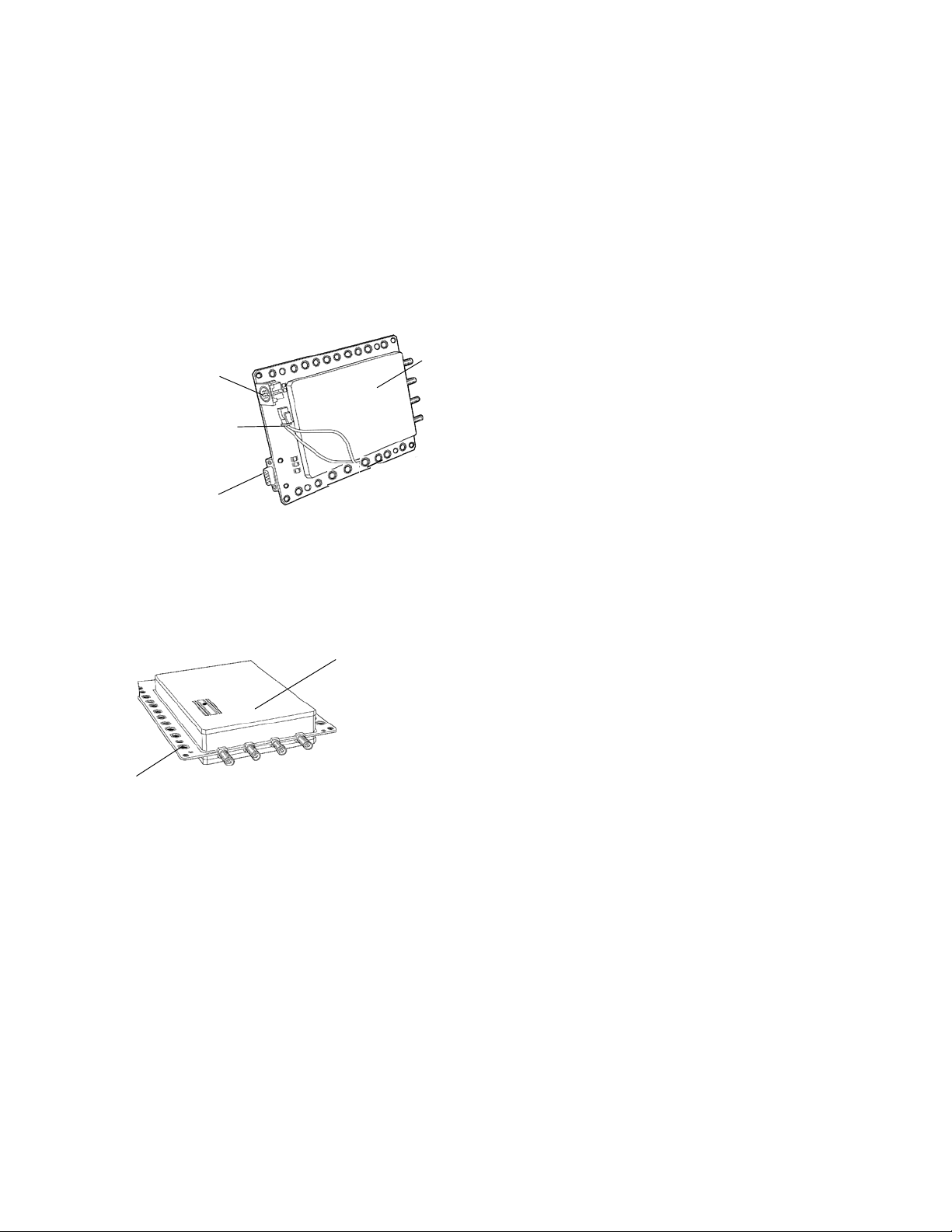
Auxiliary I/O
Connector
Cable connector
RS-232 port
IM5 Reader module
The IM5 Reader Module has holes along the sides that can be
used for mounting. For best results, attach heat sink to case via
the screwholes in the heat sink.
IM5 Reader module
Screw holes
4 IM5 Reader Module Installation and Quick Start Guide
 Loading...