


Network Support—Chapter 4
Properties
Select a COM Port from the Choose COM Port boxtoregisterforthis
device, then check Enable Wireless Printing to complete the COM port
registration. To change your COM port selection, clear (uncheck) the En-
able Wireless Printing box, select a new COM port, then check Enable
Wireless Printing again. Choose COM Port items already in use are
grayed out.
When you enable Wireless Printing, a status message is shown near the
bottom of the screen to confirm your action. To print a test page to your
printer, tap Print Test Page.
Check Default to set this printer to identify the assigned COM Port as the
WPPort in the registry. See the Bluetooth Resource Kit User’s Guide for
more details on WPPort.
Tap ok to return to the Wireless Printing page.
101700 Series Color Mobile Computer User’s Manual

Network SupportChapter —4
File Transfer
Use this page to enable your unit to receive files from another Bluetooth
device, or from any device that supports this function.
This does not apply to the 730 Computer. From this point, this transfer is
similar to an IrDA file transfer. Tap Start > Programs > File Explorer,tap
to hold the file to transfer, then select Beam File from its pop-up menu.
The system searches for a list of Bluetooth devices that will accept a connection from your unit. When the list is complete, tap on a device to
which to send the file. Note: in some cases, the user of the target device has to
“accept” the file before it is transmitted.
102 700 Series Color Mobile Computer User’s Manual
Connecting with Bluetooth
Note: While these instructions apply to many Bluetooth devices, these instructions use the Nokia 3650 for example purposes.
Before you connect to the network, make sure Bluetooth is enabled on
your 700 Color Computer before discovering and connecting to remote
devices.
Tap Start > Settings >theConnections tab>theBluetooth icon. Tap On
to activate Bluetooth, then tap ok to exit the applet.
Also make sure Bluetooth is enabled on your mobile phone. For example,
with the Nokia 3650, go to its menu, select Connect > Bluetooth,thenset
My phone’s visibility to “Shown to all.”
Do the following to establish a Bluetooth connection between your 700
Color Computer and your mobile phone, then establishing a dial-up networking session with your wireless network. Once connected, you should
be able to browse Internet websites and use other online resources from
your 700 Color Computer.
Network Support—Chapter 4
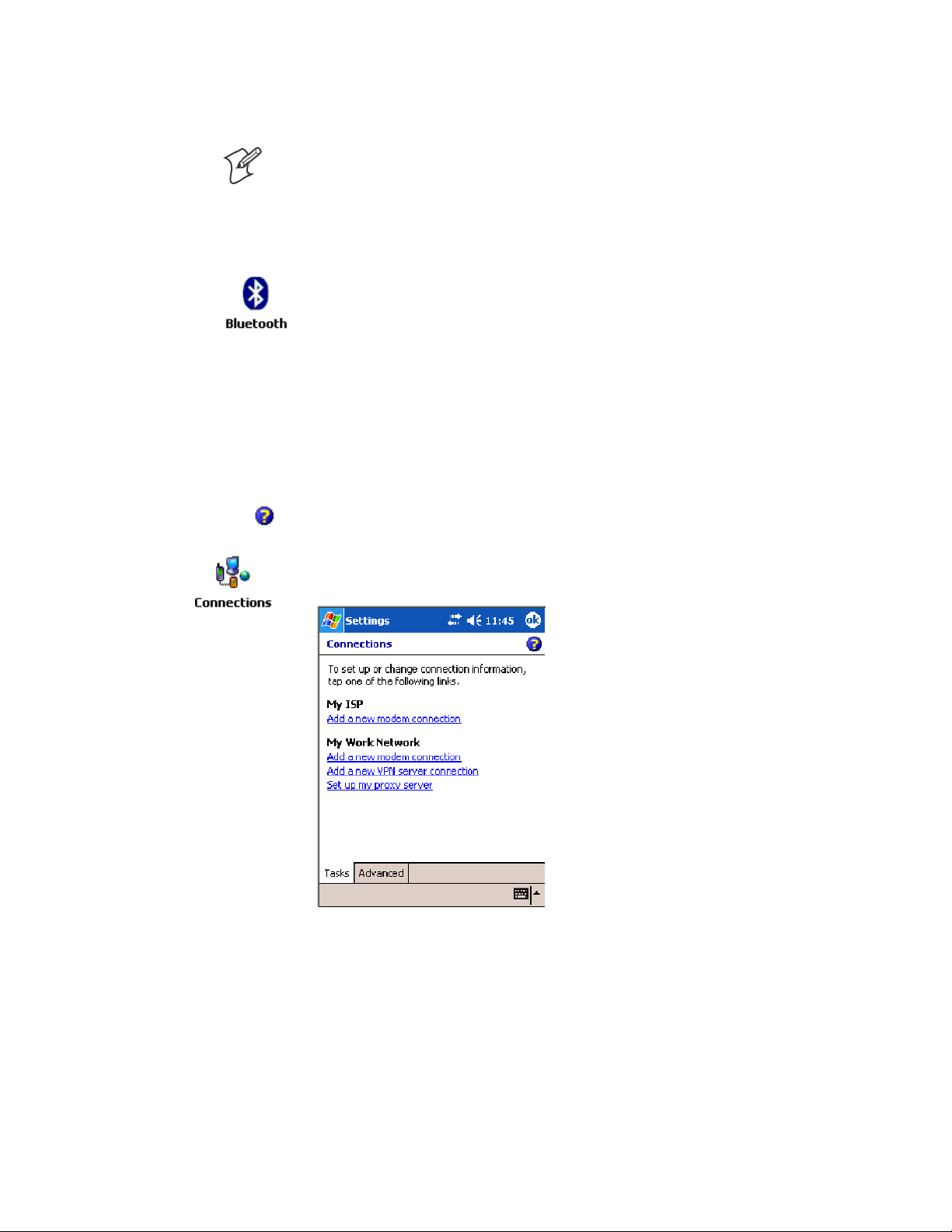
To view additional information f or any screen in the wizard or while
changing settings, tap the Help icon.
1 Tap Start > Settings >theConnections tab>theConnections icon. In
My ISP,tapAdd a new modem connection.
103700 Series Color Mobile Computer User’s Manual

Network SupportChapter —4
2 Enter a name for the connection, such as “Nokia.” In the Select a mo-
dem list, select “Bluetooth,” then tap Next to continue.
3 Tap New... if the phone is not listed in the known devices. Make sure
your Bluetooth device is turned on before you start the search.
104 700 Series Color Mobile Computer User’s Manual

Network Support—Chapter 4
4 When the discovery of devices is complete, select your Bluetooth device,
then tap Next to continue.
5 Enter the correct Device PIN on both the Bluetooth device and the 700
Color Computer, then tap Next to continue.
105700 Series Color Mobile Computer User’s Manual

Network SupportChapter —4
6 Enter a name for the device if needed, then tap Finish.
7 After bonding completes, select your Bluetooth device from the list of
bonded devices, then tap Next.
106 700 Series Color Mobile Computer User’s Manual

Network Support—Chapter 4
8 Enter the appropriate number as it should be dialed for your Bluetooth
connection, then tap Next to continue. Enter the user name, password,
and domain required for your Bluetooth device, then tap Finish.
Now you can establish a connection to your network via the Internet Explorer application. To disconnect, tap the Connectivity icon in the top
menu bar, then select Disconnect.
Local Area Networks
See the Developer’s Support web site for the latest information on network
adapters for your unit.
The 700 Color Computer is a versatile mobile computer that easily adds to
your wired or wireless data collection network. You can connect your 700
Color Computer to your network using either USB communications or
802.11b or 802.11b/g radio communications.
Configuring USB Communications
You can place the 700 Color Computer in a single dock, multidock, modem dock, or vehicle dock to transfer data to and receive data from another device using USB communications. The USB cable, single dock, multidock, modem dock, and vehicle dock are sold separately. For information
on accessories and how to order them, see “Accessories” on page 21.
To use USB communicationswith your 700 Color Computer
1 Connect the dock to the USB port of the other device using an ap-
propriate USB cable.
2 Make sure your USB device is configured for USB communications.
3 Insert the 700 Color Computer into the dock.
4 Turn on the 700 Color Computer.
107700 Series Color Mobile Computer User’s Manual

Network SupportChapter —4
Configuring 802.11 Radio Communications
Caution: Make sure all components with antennas are at least 30 cm (1
ft) apart when power is applied. Failure to comply could result in
equipment damage.
The wireless 700 Color Computer has an internal 802.11b or 802.11b/g
radio to transfer data using wireless communications. This manual assumes
you already have set up your wireless communications network, including
your access points. If you are using a UDP Plus network, have your
Intermec Application Server communicate with a host computer. Your
700 Color Computer supports TCP/IP and UDP Plus.
Configuring the Network Parameters for a TCP/IP Network
In a TCP/IP network, the 700 Color Computer communicates with a host
computer directly using TCP/IP. The access point acts as a bridge to allow
communications between the wired and wireless networks.
1 Configure the infrastructure mode, network name (SSID), host IP ad-
dress, and IP settings (if not using DHCP) on each 700 Color Computer in the network.
2 Configure security. Tap Start > Settings >theSystem tab>theWire-
less Network icon to access the Profile Wizard for the 802.11b or
802.11b/g radio module. Go to Appendix A, “Configurable Settings,”
for information.
Configuring the Network Parameters for a UDP Plus Network
In a UDP Plus network, the 700 Color Computer communicates with a
host computer through the Intermec Application Server. The Intermec
Application Server translates UDP Plus packets on the wireless network
into TCP/IP packets on the wired network and vice versa. The access
point acts as a bridge to allow communications between the wired and
wireless networks.
1 Configure the network name (SSID), controller IP address, and IP set-
tings (if not using DHCP), and controller port (set to 5555) on each
700 Color Computer in the network.
2 Configure security. Tap Start > Settings >theSystem tab>theWire-
less Network icon to access the Profile Wizard for the 802.11b or
802.11b/g radio module. Go to Appendix A, “Configurable Settings,”
for information.
The easiest way to configure the network parameters on the 700 Color
Computer is to use the Intermec Settings applet. Go to Appendix A,
“Configurable Settings.” for information.
Network Adapters
The 700 Color Computer can have up to three radios installed. The default network adapter or radio is dependent on what radios are installed in
your unit. The 700 Color Computer is capable of supporting 802.11i security requirements.
108 700 Series Color Mobile Computer User’s Manual

Network Support—Chapter 4
With the NDISTRAY pop-up menu (the Network Driver Interface Specification tray application) from the System Tray, you can specify “802.11,”
“Ethernet,” or “No Networking” to load onto your 700 Color Computer
when a cold-boot is performed. When a warm boot is performed, the 700
Color Computer loads the network set just prior to the warm boot.
The 730 Computer only has the 802.11b radio and Bluetooth. It does not
have an external antenna. Other radios are not supported.
Ethernet Communications (740, 741, 750, 751, 760, 761 Computers)
Follow the steps below to start Ethernet communications on the 700 Color
Computer. If your system does not contain an 802.11b or 802.11b/g
radio, then Ethernet networking using DHCP is selected as the default.
When “Built-in Ethernet” is selected from the NDISTRAY pop-up menu,
then the Ethernet icon shown to t he left appears in the System Tray as
circled in the following illustration.
109700 Series Color Mobile Computer User’s Manual

Network SupportChapter —4
Wireless 802.11 Communications
When “Wireless 802.11” is selected via the NDISTRAY pop-up menu,
the Wireless 802.11 antenna icon shown to the left appears in the system
tray as circled in the following illustration.
No Networking
When “No networking” is selected from the NDISTRAY pop-up menu,
the disconnected icon shown to the left appears in the system tray as
circled in the following illustration.
Network Selection APIs
The Network Selection APIs change the network adapter configuration
programmatically. Both drivers support the same IOCTL function numbers for loading and unloading the drivers. Go to Chapter 7, “Programming,” to see the APIs.
110 700 Series Color Mobile Computer User’s Manual

Network Connections
Network Support—Chapter 4
From the 700 Color Computer, tap Start > Settings >theConnections
tab>theConnections icon > the Advanced tab > Network Card or the
Network Adapters tab to access the network connections for this unit.
Make the changes necessary for your network, then tap ok when finished.
Creating a Wireless Network Connection
Use the Wireless Network applet for more security choices and better
roaming behavior. See Appendix A for information.
Networks already configured are preferred networks and are listed in
Wireless networks. You can connect to only preferred networks or search
for and connect to any available network.
A wireless network can be added either when the network is detected, or
manually by entering settings information. To determine if authentication
information is needed, see your network administrator.
1 Tap Start > Settings >theConnections tab>theConnections icon.
111700 Series Color Mobile Computer User’s Manual

Network SupportChapter —4
2 Tap the Advanced tab > Network Card >theWireless tab > Add New .
3 Tap the General tab, then enter a network name. If the network was
detected, the network name is entered and cannot be changed.
From Connects to, select to what your network is to connect. If you
select “Work,” you can do a vpn connection or use proxy servers. If you
select “The Internet,” you can connect directly to the internet.
To connect to an ad-hoc connection, select This is a device-to-device
(ad-hoc) connection.
4 Tap the Network Key tab, then do the following:
To Disable Authentication
a Set Authentication to either “Open” if WEP keys are not required;
or “Shared” when WEP keys are required for association.
112 700 Series Color Mobile Computer User’s Manual

Network Support—Chapter 4
b Set Data Encryption to “Disabled.”
To Enable WEP Encryption
a Set Authentication to either “Open” if WEP keys are not required;
or “Shared” when WEP keys are required for association.
b Set Data Encryption to “WEP.”
c To change the network key, clear The Key is provided for me auto-
matically box, then enter the new Network key and select the ap-
propriate Key index.
Note: The following information applies when you have Enable Microsoft’s Wireless Zero Config checked via the Wireless Network applet (see
Appendix A, “Configurable Settings”).
113700 Series Color Mobile Computer User’s Manual

Network SupportChapter —4
To Enable WPA Authentication (730, 751, 751, 761 Computers)
a Set Authentication to “WPA” (see page 236).
b Set Data Encryption to either “WEP” or “TKIP” (see page 236).
To Enable WPA Authentication Using a Preshared Key (730, 741, 751, 761 Computers)
a Set Authentication to “WPA-PSK” (see page 236).
b Set Data Encryption to either “WEP” or “TKIP” (see page 236).
c Enter the new Network key.
114 700 Series Color Mobile Computer User’s Manual

Network Support—Chapter 4
5 Tap the 802.1x tab, select either “PEAP” or “Smart Card or Certificate”
for the EAP type,thentapProperties to adjust its settings.
6 Tap ok to return to the Configure Wireless Network screen.
7 From the Networks to access drop-down list, select “All Available,”
“Only access points,” or “Only computer-to-computer” depending on
the type of networks to which you connect.
To connect only to networks you have already configured, clear Auto-
matically connect to non-preferred networks.Tapok to close this
screen.
Note: If you select to automatically connect to non-preferred networks,
your device detects any new networks and provide you the opportunity to
configure them.
115700 Series Color Mobile Computer User’s Manual

Network SupportChapter —4
AutoIP/DHCP
Automatic Private IP Addressing (AutoIP) is enabled by default in
Windows Mobile 2003. To remain compatible with other versions of
Pocket PC, this setting needs to be enabled. You can configure the registry
settings in the following to set the required AutoIP/DHCP behavior:
S For Ethernet: HKEY_LOCAL_MACHINE\Comm\LAN9001\TcpIp
S Fot 802.11: HKEY_LOCAL_MACHINE\Comm\NETWLAN1\TcpIp
Other registry keys that can modify the behavior of AutoIP are as follows.
You can find the appropriate settings and behavior of each of these keys in
Microsoft Help.
S AutoInterval
S AutoMask
S AutoSubnet
S AutoIP
S AutoSeed
When a TCP/IP client cannot find a DHCP server, it generates an AutoIP
address from the 169.254.xxx.xxx block. The client then tries to check f or
a DHCP server every 15 seconds and if a DHCP server is found, the client
drops the AutoIP address and uses the address from the DHCP server.
In the MSDN Windows CE documentation available out on the Microsoft Developer Network web site (www. msdn.com), see “Automatic Client
Configuration” for more information on AutoIP.
To disable AutoIP, set the AutoCfg r egistry entry to “0.” If a DHCP server cannot be found, instead of using AutoIP, the system will display the
“Unable to obtain a server assigned IP address” message.
Note: If you try to disable AutoIP using a CAB file to set the registry value
for AutoIP, remember to set the EnableDHCP value to “1” to keep
DHCP enabled
Note: To extend the number of attempts that a DHCP client makes to get
a DHCP address, use the DhcpRetryDialogue and DhcpMaxRetry registry
settings.
Note: Change the AutoInterval registry key value to make the client retry
more often to obtain a DHCP address.
Wide Area Networks
The 700 Color Computer does not support wide area networks.
Phone Applications
The following phone applications apply to certain configurations. See the
chart on page 98 to learn which applies to your 700 Color Computer.
116 700 Series Color Mobile Computer User’s Manual

Microsoft Phone Application (761 Computers with CDMA Radios)
With the WAN radio module installed in your 761 Computer, you can
send and receive telephone calls. Use the speaker on the back of the computer as your earpiece and use the connector on the bottom of the computer for your mouthpiece.
Data Provisioning (Sprint)
Note: If you wish to do this activation another time, tap Cancel to close
this wizard, then tap Yes.
It is necessary to initiate activation before using your Microsoft Phone application. Below are the instructions:
Network Support—Chapter 4
1 Tap Start > Programs >thePhone desktop icon or tap Start > Phone
from the Today screen to access the application which processes your
phone calls. Tap the Close button in the upper right corner of this ap-
plication to close.
2 From the Phone application, tap Tools > Activation Wizard.
3 Have your activation code, phone number (MDN), and MSID infor-
mation ready before you tap Next to continue. You can get this infor-
mation from your network provider.
117700 Series Color Mobile Computer User’s Manual

Network SupportChapter —4
4 Enter your 6-digit activation code, then tap Next to continue.
5 Enter the phone number and MSID from Sprint, tap Next to continue.
6 The application prompts whether the information entered is correct. If
so, tap Yes to continue, else tap No to return to the previous screen.
118 700 Series Color Mobile Computer User’s Manual

Network Support—Chapter 4
7 Note that voice service is available immediately. Data service take a
minimum of four hours of activation before you can use the service. If
after four hours, a data connection is not established, see “Data Provisioning” on page 117 to manually launch data provisioning.
The application acknowledges that your phone will be in service in four
hours. Tap Finish to close the wizard.
Data Provisioning (Verizon)
Note: If you wish to do this activation another time, tap Cancel to close
this wizard, then tap Yes.
It is necessary to initiate activation before using your Microsoft Phone application. Below are the instructions:
1 Tap Start > Programs >thePhone desktop icon or tap Start > Phone
from the Today screen to access the application which processes your
phone calls. Tap the Close button in the upper right corner of this ap-
plication to close.
2 From the Phone application, tap Tools > Activation Wizard.
119700 Series Color Mobile Computer User’s Manual

Network SupportChapter —4
3 Tap Auto to initiate the activation.
4 The application acknowledges that your phone is now in service. Tap
Finish to close the wizard.
Phone Application
Note: Wait at least four hours after Sprint activation is complete before
using this application. Data provisioning should occur automatically. Network information about your 761 Computer needs to propagate through
the Sprint Network after the activation is complete.
If data provisioning does not occur automatically, tap Start > Settings >
the Personal tab>thePhone icon. Tap the Data tab, then tap Provision
to initiate a session.
120 700 Series Color Mobile Computer User’s Manual

Network Support—Chapter 4
Tap the appropriate keys to enter a telephone number, then tap Talk to
dial the number. Tap End to “hang up” the phone.
Tap this to backspace one digit.
Tap this to dial the phone number
shown above the keypad.
Tap this to select a previously
dialed number.
Tap this to view your previous calls.
Tap this to “hang up” your current
call.
Tap this toggle the mute option.
Tap this to access the Contacts application.
Tap this to access the Notes application.
Speed Dial
Tap Speed Dial to select a telephone number with which the 761 Computer is to dial automatically. To add to this list, use the Contacts application. See Chapter 2, “Windows Mobile 2003,” for more information
about the Contacts application.
121700 Series Color Mobile Computer User’s Manual

Network SupportChapter —4
Call History
Tap Call History to note the telephone numbers that were previously
dialed from this 761 Computer.
Tools
Use the Tools menu to send a voice mail, access the Activation Wizard,
send an SMS email message, or configure phone settings.
S Tap Tools > Voice Mail to call and leave a voice message.
S Tap Tools > Activation Wizard to access the wizard with which to acti-
vate your 761 Computer. Be sure to have an activation code, a phone
number, and MSID information ready. See page 117 for instructions on
using this wizard.
Sprint Networks
122 700 Series Color Mobile Computer User’s Manual
Verizon Networks

Network Support—Chapter 4
S Tap Tools > Send SMS tab to access the Inbox application and send an
SMS (Short Messaging Service) message. Be sure to have an SMS number ready to send the message — this is usually the mobile phone number. See Chapter 2, “Windows Mobile 2003,” for Inbox information.
Phone Settings
Either select Tools > Options from the P hone application or select Start >
Settings >thePersonal tab>thePhone icon to access the applet.
S Tap the Phone tab to customize your phone settings such as the ring
type and ring tone to use for incoming calls, and the keypad tone to use
when entering phone numbers. Tap Other Settings to go to the Sounds
& Notifications applet. Select Start > Help for more information.
123700 Series Color Mobile Computer User’s Manual

Network SupportChapter —4
S Tap the Location tab to toggle between your location being visible for
everyone to detect and hiding your location from everyone except 911.
Sprint Networks
Verizon Networks
S Tap the Data tab to either reset your connection settings for PCS Vi-
sion or update your PCS Vision profile.
For Sprint Networks, if your 761 Computer is unable to make a data
connection and it has been more than four hours since activation, you
can launch data provisioning from this screen. Tap Provision,thenfollow the prompts. It takes a few minutes to set up the data connections.
Note: The data provisioning process can be automatically initiated by
the Sprint network, by attempting to make a cellular line connection to
the WAN before the 761 Computer is data provisioned, or by manually
starting the connections through this screen. Intermec recommends that
Sprint Network “push” the data provisioning to your unit. This should occur shortly after the voice activation is complete.
Sprint Networks
124 700 Series Color Mobile Computer User’s Manual
Verizon Networks

S Tap the System tab to select t he applicable function.
Sprint Networks Verizon Networks
Network Support—Chapter 4
S Tap the Phone Info tab to view the phone settings.
Sprint Networks Verizon Networks
Microsoft Phone Application (761 Computers with GSM Radios)
With the WAN radio module installed in your 761 Computer, you can
send and receive telephone calls. Use the speaker on the back of the computer as your earpiece and use the connector on the bottom of the computer for your mouthpiece.
Tap Start > Settings >thePhone desktopiconfromthePersonal tab or
tap Start > Phone from the Today screen to access the application which
processes your phone calls. Tap the Close button in the upper right corner
of this application to close.
125700 Series Color Mobile Computer User’s Manual

Network SupportChapter —4
Activation
The GSM phone is activated via a SIM card that you can purchase from
your network provider.
Phone Application
Tap the appropriate keys to enter a telephone number, then tap Talk to
dial the number.
Tap this to backspace one digit.
Tap this to view your previous calls.
Tap this to select a previously
dialed number.
Tap this to dial the phone number
shown above the keypad.
Tap this toggle the mute option.
Tap this to access the Contacts application.
Tap this to access the Notes application.
Call History
Tap Call History to note the telephone numbers that were previously
dialed from this 761 Computer.
126 700 Series Color Mobile Computer User’s Manual

Network Support—Chapter 4
Speed Dial
Tap Speed Dial to select a telephone number with which the 761 Computer is to dial automatically. To add to this list, use the Contacts application. See Chapter 2, “Windows Mobile 2003,” for more information
about the Contacts application.
Tools
Tap Tools > Send SMS tab to access the Inbox application and send an
SMS (Short Messaging Service) message. Be sure to have an SMS number
ready to send the message — this is usually the mobile phone number. See
Chapter 2, “Windows Mobile 2003,” for information about Inbox.
127700 Series Color Mobile Computer User’s Manual

Network SupportChapter —4
Phone Settings
Either select Tools > Options from the P hone application or select Start >
Settings >thePersonal tab>thePhone icon to access the applet.
S Tap the Phone tab to customize your phone settings such as the ring
type and ring tone to use for incoming calls, and the keypad tone to use
when entering phone numbers. Tap Other Settings to go to the Sounds
& Notifications applet.
S Tap the Services tab to access settings for any of the provided services.
128 700 Series Color Mobile Computer User’s Manual

Network Support—Chapter 4
Tap any of the settings, then tap Get Settings.Makeyourchanges,then
tap ok to return to the Settings screen. Below is a sample Settings
screen.
S Tap the Network tab to find, set, or select the type of network on
which this phone is to communicate.
129700 Series Color Mobile Computer User’s Manual

Network SupportChapter —4
Phone Information
To learn the latest phone settings, including the manufacturer, model,
firmware rev, and IMEI, select Start > Settings >theSystem tab, then tap
the WAN Info desktop icon. Tap ok when finished.
SB555 Watcher (760 Computers with CDMA Radios)
The SB555 Watcher program is used on the 760 Computer with CDMA
radios only. Use this primarily to activate the WAN radio. Once the WAN
radio is activated, you can remove the SB555 Watcher program from the
760 Computer.
This tells you how to set up your CDMA radio in your 760 Computer.
Below are terms to familiarize you with CDMA radio technology:
Note: Set up and provision information is also available in the 700 Color
CDMA Radio Setup Quick Start Guide P/N: 962-054-063.
Activation The process of programming the radio with the lock code (MSL) and phone number (MIN) to
allow it to communicate on the provider’s network. Once activation is complete you can make
voice calls (if enabled by the carrier) with the mobile computer.
Data Provisioning Th e process of activating the ability for the CDMA radio to establish data connections, such as
connecting to the Internet. The CDMA radio makes data connection only after it is activated
and data provisioned.
NID (Network ID) A numeric value programmed into the CDMA radio at the factory or during the activation
process. Your carrier may or may not use this value, but your carrier may provide this for activation purposes.
SID (System ID) A numeric value programmed into the CDMA radio at the factory or during the activation
process. This number is used by your carrier to determine if the radio belongs to its CDMA
network. Your carrier may provide this number for activation purposes.
Note: Descriptions in this chapter are for Sprint PCS, Bell Mobility, Telus, and Verizon Networks versions of the SB555 Watcher program. Other carriers may be added pending regulatory and carrier approval.
130 700 Series Color Mobile Computer User’s Manual

Network Support—Chapter 4
Copying CDMA Radio Module CAB Files from Intermec Web Site
Copy CAB files from the Intermec web site at www.intermec.com onto
your desktop. Intermec recommends one of two methods with which to
load these CAB files onto your 760 Computer:
S via the Microsoft ActiveSync application
S via a CompactFlash or Secure Digital storage card. See Chapter 3,
“Installing Applications,” for information about these methods.
Via Microsoft ActiveSync
You can transfer files from your desktop to your 760 Computer via Microsoft ActiveSync. See Chapter 2,“Windows Mobile 2003” for more infor-
mation about ActiveSync.
1 Obtain software from the Intermec web site as described earlier. Down-
load the software to any location on your 760 Computer, such as the
Temp folder via the My Device root location.
2 Tap the carrier CAB file to install the application.
3 Go to “Finishing the Installation” on page 132.
Via a CompactFlash or Secure Digital Storage Card
Note: These instructions are based on d efault locations. You can change
the location to which to copy your CAB files.
1 Make sure the Registry Restore feature on your 760 Computer is dis-
abled. Select Start > Settings >theSystem tab. Tap the Utilities desktop icon, the Registry Save tab, then clear the Enable Registry Save box.
2 Copy the CAB files for your carrier to your CompactFlash or Secure
Digital storage card after downloading it from the web site.
3 Cold-boot your 760 Computer. Remove the AB10 battery pack and
press the reset button in the bottom of the battery compartment.
4 Go through the normal getting started steps detailed in your 700 Color
CDMA Radio Setup Quick Start Guide.
131700 Series Color Mobile Computer User’s Manual

Network SupportChapter —4
5 Install the CompactFlash or Secure Digital memory card into the card
slot in your 760 Computer. Note that if you do not want the CAB files
erased after installation, set the CAB file attributes to “read-only” after copying them to the storage card.
6 Tap Start > Programs >theFile Explorer icon on the 760 Computer.
7 Tap the pull-down menu for My Documents and tap the My Device
root location.
8 If you are using a CompactFlash storage card,
tap Storage Card.
If you are using an Secure Digital storage card,
tap SDMMC Disk.
9 Scroll down, tap the Sprint Watcher CAB file to install the application.
Finishing the Installation
Do the following to run the SB555 Watcher application. Be sure to do
step 1 as it is important to perform a warm-boot on your 760 Computer.
Upon restart, the Watcher application sets up on the 760 Computer for
activation.
1 Tap Start > Programs >theWatcher icon.
2 Tap Yes, I accept to accept the license agreement, tap OK to continue.
Note this license agreement does not appear again after this installation.
3 Tap OK for the 760 Computer to perform a warm-boot.
132 700 Series Color Mobile Computer User’s Manual

Network Support—Chapter 4
Activation
Note: Set the date and time before doing this activation.
SB555 Watcher is for activation and data provisioning. Once you enable
voice capability, data capability, or both depending on the carrier, remove
this program from the system by cold-booting your computer.
Do not use the SB555 Watcher to make data/voice calls on a daily basis:
S The SB555 Watcher application is a third-party application unaware of
certain power management methods used in your 760 Computer. Therefore,
the application consumes more power than necessary.
S The application size consumes memory better used for application data.
The process of setting up the account with your carrier and enabling the
CDMA WAN radio in your 760 Computer is called activation. To properly function, program the CDMA device with the necessary information
and set up the network carrier account. If either piece has errors, the device does not function on the CDMA network.
The CDMA radio is pre-programmed for a specific carrier, such as Sprint,
Telus, Bell Mobility, Verizon, etc.). Therefore, information about your
radio should already be in your carrier’s database.
You need to notify the carrier and set up mobile accounts for each unit
you are activating. The Electronic Serial Number (ESN hex 63xxxxxx)
that you need to supply to your carrier is located in two places:
S On the outside of the 760 Computer shipping box.
S On the inside of the 760 Computer battery compartment. The label
includes the term “ESN” and a bar code along with the serial number.
The ESN comes in both decimal and hexadecimal formats. Most carriers
accept either format, but with a preference for the decimal format. You
only need to provide one number to your carrier.
S The decimal format consists of 11 digits, beginning with “099.”
S The hexadecimal format is an 8-digit number, beginning with “63.”
Accounts for Verizon and Sprint carriers can be set up for data only. Canadian carriers (Telus and Bell Mobility) can be set for data only, voice only,
or both voice and data. This is determined by your application and the
services your carrier offers.
After the all ESNs are provided to the carrier and the carrier has established the accounts, you will be provided with the lock codes and telephone numbers needed to complete the activation process. You use the
SB555 Watcher program to accomplish this task. Note this for future use.
Note: Ensure that you receive a spreadsheet with your order that calls out
all ESNs in both decimal and hexadecimal formats.
Note: Keep the activation information for your devices in a safe, accessible
place should you have any future issues.
Note: Not all of the elements listed are required by all service providers.
133700 Series Color Mobile Computer User’s Manual

Network SupportChapter —4
ESN of the modem
Lock/ActivationCode(maybetermedoneofthefollowing):
S MSL — Master Subsidy Lock
S OTSL — OneTime Subsidy Lock
S SPC — Service Provisioning Code
S OTKSL — One Time Key Subsidy Lock
SID (System ID)
NID (Network ID)
User Name
Password
MIN
MSD
MDN
Note: The activation process for your Watcher version may vary from the
following steps. Thus, you may not have to do all of them.
1 Tap Start > Programs >theWatcher icon or tap the Watcher icon from
the NDISTRAY via the Today screen (circled in the following illustra-
tion) to launch the SB555 Watcher program.
2 The Activation Wizard should start automatically. If not, then tap
Admin > Activation Wizard from the bottom of the screen.
3 Tap Next to move from one screen prompt to the next.
134 700 Series Color Mobile Computer User’s Manual

Network Support—Chapter 4
4 When you reach the Activation screen, select Manual Activation.
5 At the appropriate screen, enter the Activation Code (OTSL, MSL,
OTKSL, or SPC) provided by your carrier and tap Next.
6 Enter the phone number provided when your 760 Computer was acti-
vated and tap Next.
Verizon Automated Activation Process
Note: This process takes approximately 60 seconds.
Do the following to activate Verizon on your 760 Computer:
1 Tap Start > Programs >theWatcher icon.
135700 Series Color Mobile Computer User’s Manual

Network SupportChapter —4
2 Tap Yes, I accept to accept the license agreement, tap OK to continue.
Note this license agreement does not appear again after this installation.
3 Select OK to initiate the warm-boot, then after the warm-boot, start the
Watcher program again, select Automated Activation,thenclickNext.
Note: YoumustbeintheVerizoncoverageareatoactivateyour760
Computer and only in the location of intended use.
4 Click Next,clickNext again to dial the number displayed on the screen.
5 The activation process starts automatically.
6 You will see a series of unlock codes on your screen.
7 Click the Connect button to connect to the carrier’s network.
8 Select Start > Internet Explorer, then choose a web site. Your unit is
now successfully activated.
136 700 Series Color Mobile Computer User’s Manual

Network Support—Chapter 4
9 Perform a cold-boot on your 760 Computer to uninstall the Watcher
application, which is intended for activation purposes only. Use the following for establishing and maintaining connection to the WAN radio:
S Custom application using Intermec WWAN Toolkit API
S Custom customer application using Connection Manager Interface
Note: When connecting to the WAN radio via Pocket PC Connection
Manager, use the 10-digit phone number@vzw3g.com for the user
name (such as 1234567890@vzw3g.com) and “vzw” for the password.
Sprint Automated Activation Process
Note: Sprint PCS uses a data provisioning method termed IOTA (Internet
Over The Air) to complete its activation and data enablement. These steps
detail how to properly activate and data provision your 760 Computer.
1 Give Sprint your ESN (either on the box or on a label inside the battery
compartment), rate plan, and account information. The label would include the term “ESN” and a bar code along with the serial number.
2 Sprint provides you with the following for each ESN:
S MDN, such as 214-555-5555
S MSID, such as 214-555-5555
S MSL/OTKSL (Activation Code), such as 945614
S NAI (Network Access Identifier), such as the following:
CustomerName103@sprintpcs.com
Use a Secure Digital storage card with only the Sprint_Watcher_PPC_
2002-03xxx.CAB file in the “\SDMMC\Cabfiles” folder. Other CAB files
in the “\SDMMC\Cabfiles” folder may cause problems with testing, remove or uninstall these before proceeding. At least 80% (4 of 5 bars)
CDMA signal strength for a successful over-the-air activation.
Download and Activate Sprint Watcher
1 Make sure the Registry Restore feature on your 760 Computer is dis-
abled. Select Start > Settings >theSystem tab. Tap the Utilities desktop icon, then the Registry Save tab. Clear Enable Registry Save.
137700 Series Color Mobile Computer User’s Manual

Network SupportChapter —4
2 Perform a cold-boot on your 760 Computer, then go through the nor-
mal Pocket PC set-up (i.e. Align Screen etc.).
3 Important! Set the Date and Time.
4 Tap the Sprint_Watcher_PPC_2002-03xxx.CAB file to perform the
installation.
5 Perform a warm-boot on your 760 Computer to load the CAB file.
6 From the Today screen, tap the LAN Network icon in the System Tray.
7 In the NDISTRAY pop-up menu (the Network Driver Interface Speci-
fication tray application), select No Networking and Auto FTP Off.
Tap anywhere on the screen to close the menu.
8 Tap Start > Programs >theWatcher icon to launch the SB555 Watch-
er program.
9 Tap Yes, I accept to accept the license agreement, then tap OK to con-
tinue. This license agreement does not appear again after this installation.
Tap OK for the 760 Computer to perform a warm-boot and complete the
installation.
138 700 Series Color Mobile Computer User’s Manual

Network Support—Chapter 4
Using Sprint Watcher
Before you start using the Sprint Watcher application, make sure you
match the correct ESN with each 760 Computer and that you have at least
80% CDMA signal strength.
TheESNthatyougivetoyourprovideriseitherontheboxoronalabel
inside the battery compartment. The label would include the “ESN” term
and a bar code along with the serial number.
1 Tap Start > Programs >theWatcher icon or tap the Watcher icon from
the NDISTRAY via the Today screen (circled in the following illustra-
tion) to launch the SB555 Watcher program.
2 If your 760 Computer was not previously activated, Watcher automati-
cally starts the Activation Wizard. Otherwise, select Manual Activation
to continue.
139700 Series Color Mobile Computer User’s Manual

Network SupportChapter —4
3 Enter the MSL or lock code received from Sprint.
4 Enter the phone number (MIN) and MSID received from Sprint.
These numbers may be the same.
5 After entering the phone number and MSID, the modem then resets
and the Watcher application displays the screens shown here:
Note: If the “searching for SB555” screen does not proceed to the next
screen after 30-40 seconds, perform a warm-boot on your 760 Computer, then restart the Watcher program.
140 700 Series Color Mobile Computer User’s Manual

Network Support—Chapter 4
Data Provisioning
At this point, the activation on the Sprint network is complete. It is recommended by Sprint to wait before you launch data provisioning to allow
time for the activation to propagate through your Sprint network.
Before you manually launch data provisioning, wait at least 30 minutes. In
some cases, you may have to wait up to two hours.
1 If Data Provisioning does not start automatically, select Admin > Data
Provisioning from the bottom menu bar.
2 Tap Yes to proceed with data provisioning.
3 Activation over the air typically takes 1–20 minutes.
If data provisioning fails, do the following:
S If Data Provisioning fails and the message “could not prepare data ser-
vices, please contact Sprint” displays, retry the Data Provisioning step by
tapping the “Admin” menu icon at the bottom of the Watcher screen.
Select “Data Provisioning...” and answer “yes” to the request.
141700 Series Color Mobile Computer User’s Manual

Network SupportChapter —4
S If after several attempts to complete the Data Provisioning over the air,
it may be necessary to manually enter the data activation method.
S Go to Intermec Knowledge Central www.intermec.com, then select Ser-
vice & Support > Knowledge Central) to learn about manual activa-
tion. The article (number 5749) is titled How to Manually Activate a
Sprint CDMA WAN Radio in the 760 Device.
4 The following screen appears once data provisioning is complete:
5 Test the data connection by tapping on the “connect” button to make a
data connection to the network. Watcher progresses through the following two screens. Once you see the second screen you know that your
mobile computer has successfully connected to the 1XRTT network.
142 700 Series Color Mobile Computer User’s Manual

Network Support—Chapter 4
6 Select Start > Internet Explorer,thentapPocket Internet Explorer to
choose a web site. Your unit is now successfully activated.
Perform a cold-boot on your 760 Computer to uninstall the Watcher application. Watcher is intended for activation purposes only. Use the following to establish and maintain connection to the WAN radio:
S Custom application using Intermec WWAN Toolkit API
S Custom customer application using Connection Manager Interface
Telus and Bell Mobility Activation
Activation of Bell Mobility and Telus are similar to the first portion of the
Sprint activation process. Follow the instructions for manual activation
using the Bell Mobility Watcher.CAB or Telus Watcher.CAB file to install
the applicable application. Enter the activation lock codes and phone numbers as requested.
Bell Mobility Telus
Username 10 digit phone
number@1xbell.ca
Password Original Voice Mail system password (usually a 4
digit #) available from activating organizations.
SID 16420 16422
10-digit phone
number@1x.telusmobility.com
The 11-digit ES N printed inside the 760 Computer battery compartment, begins with 099.
AT Command Interface (760 Computers)
This interface specification is based on the following recommendation:
S ETSI GSM 07.05:
European Digital Cellular Telecommunication System (phase 2)
Use of DTE-DCE interface for Short message and cell broadcast service.
S ETSI GSM 07.07:
European Digital Cellular Telecommunication System (phase 2)
AT command set for GSM Mobile Equipment.
S ITU-T Recommendation V.25 ter
Serial asynchronous automatic dialing and control.
143700 Series Color Mobile Computer User’s Manual

Network SupportChapter —4
Note: You need the Adobe Acrobat Reader application to view a PDF document. Go to www.adobe.com/prodindex/acrobat/readstep.html to install
or download the latest Adobe Acrobat Reader.
Command Set for Sierra Wireless SB555
Use the AT command interface from Sierra Wireless to program the
CDMA/1xRTT SB555 radio module. Documentation for this interface is
available via the following URL. Click the “General AT command reference” link for a PDF document, which is 680 KB in size.
Command Set for Siemens MC45, MC46, or MC75
Use the MC45, MC46, or MC75 AT command interface from Siemens
AG to program the GPRS/GSM MC45, MC46, or MC75 radio module.
The following documentation is available either from Intermec or from
Siemens AG. Contact either your Intermec representative or the Siemens
AG support personnel for information.
S MC45 Siemens Cellular Engine AT Command Set
S MC46 Siemens Cellular Engine AT Command Set
S MC75 Siemens Cellular Engine AT Command Set
Testing the AT Commands(760, 761, 761B)
These commands can be sent to either WAN radio by setting up a dial-up
networking connection. Do the following to initiate this connection and
test these commands to your radio. These screens are from a 760 Computer.
1 From the 760, 761, or 761B Computer, select Start > Settings >the
Connections tab > Connections.UnderMy ISP,tapAdd a new mo-
dem connection.
144 700 Series Color Mobile Computer User’s Manual

Network Support—Chapter 4
2 Enter a name for the connection, select the appropriate modem (as
listed here) from the Select a modem drop-down list, then tap Next to
continue.
S 760 Computers “WANA on COM4”
S 761 Computers “WANB on COM5”
S 761B Computers “Virtual WANB”
3 Enter a phone number as it should be dialed, then tap Next to continue.
Select Start > Help for more information or tap use dialing rules to
make modifications. Note that this screen may vary based on dialing rules.
Note that when you make a manual dial-up connection, a number is
not required. You may type in any number with at least one digit.
145700 Series Color Mobile Computer User’s Manual

Network SupportChapter —4
4 Tap Advanced to adjust the baud rate.
5 Select the appropriate baud rate (as listed here) from the Baud rate
drop-down list.
S 760 Computers 115200
S 761 Computers 57600
S 761B Computers 110
146 700 Series Color Mobile Computer User’s Manual

Network Support—Chapter 4
6 Tap the Port Settings tab, check Enter dialing commands manually,
tap ok,thentapFinish to return to the Connections screen.
7 Tap Manage existing connections from the Connections page, press
and hold the new connection for a pop-up menu, then tap Connect to
initiate the connection.
8 Wait about ten seconds for the Network Log On screen, then tap OK.
You do not need to enter information within the Network Log On screen.
Use either the onscreen keyboard, or press the keys to type any of the AT
commands provided. Press or tap Enter to send each command. The results of each command sent will print onscreen. Note that each “AT” com-
mand must start with the “at” characters.
S To see what you typed onscreen, type “ate1” to initiate the AT Echo
command, then press Enter.
147700 Series Color Mobile Computer User’s Manual

Network SupportChapter —4
Remote Access (Modems)
You can set up connections to the Internet and corporate network at work
to do such activities as browsing the Internet or intranet, sending and receiving e-mail and instant messages, and synchronizing information using
ActiveSync. Connections can be made using a wireless network.
Your 700 Series Computer has two groups of connection settings: My ISP
and My Work Network. Use My ISP settings to connect to the Internet.
Use My Work Network settings to connect to any private network.
S My ISP: Once connected, you can send and receive e-mail messages by
using Inbox and v iew Web or WAP pages by using Pocket Internet Explorer. The communication software for creating an ISP connection is
already installed on your 700 Series Computer. Your service provider
provides the software needed to install other services, such as paging and
fax services. If this is the method you want to use, see “Connecting to
an Internet Service Provider” below.
S My Work Network: Connect to the network at your company or orga-
nization where you work. Once connected, you can send and receive
e-mail messages by using Inbox, view Web or WAP pages by using
Pocket Internet Explorer, and synchronize with your desktop. If this is
the method you want to use, see “Connecting to Work” on page 151.
Connecting to an Internet Service Provider (ISP)
You can use your ISP connection to do e-mail and Web or WAP pages.
Get your dial-up access telephone number, user name, and password from
your ISP. Note some require additional information, such as MSN/username.
To see more information regarding any screen in the wizard or while
changing settings, tap the Help icon.
1 Tap Start > Settings >theConnections tab>theConnections icon. In
My ISP,tapAdd a new modem connection.
148 700 Series Color Mobile Computer User’s Manual

Network Support—Chapter 4
2 Enter a name for the connection, such as “ISP Connection.” If using an
external modem with a cable, select “Hayes Compatible on COM1”
from the Select a modem list. Tap Next to continue.
3 Enter the access phone number, then tap Next.
149700 Series Color Mobile Computer User’s Manual

Network SupportChapter —4
4 Enter the user name, password, and domain (if provided by an ISP or
your network administrator), then tap Finish.
5 Tap the Advanced tab from the Connections screen, then tap Select
Location to specify your current location. These settings apply to all
connections. Tap Use dialing rules,tapOK,then tap Edit to continue.
730, 740, 750, 760 Screens 741, 751, 761 Screens
150 700 Series Color Mobile Computer User’s Manual

Network Support—Chapter 4
6 Specify your current phone type. If your phone type is pulse dialing,
check the Pulse dialing box. If your type is tone dialing (as most phone
lines are), then clear the Pulse dialing box. Continue to tap ok to close
each page and return to the Settings page.
Connecting to Work
To start the connection, use one of the following programs:
S Send and receive e-mail messages by using Inbox. Before you can use
Inbox, you need to provide the information it needs to communicate
with the e-mail server.
S Visit Web and WAP pages by using Pocket Internet Explorer. For more
information, see “Pocket Internet Explorer” on page 79.
S Send and receive instant messages with MSN Messenger. For more in-
formation, see “MSN Messenger” on page 73.
Note: To change modem connection settings in My ISP, tap Manage
existing connections. Select the desired modem connection, tap Settings,
and follow the instructions on the screen.
If you have access to a network at work, you can send e-mail messages,
view intranet pages, synchronize your 700 Color Computer, and possibly
access the Internet. You can connect to work by creating a modem connection via a RAS (Remote Access Server) account. Before you can create this
modem connection, your network administrator needs to set up a RAS
account for you. Your network administrator may also give you Virtual
Private Network (VPN) settings.
Note: To change modem connection settings in My Work Network, tap
Manage existing connections. Select the desired modem connection, tap
Edit, and follow the instructions on the screen.
To view additional information f or any screen in the wizard or while
changing settings, tap the Help icon.
151700 Series Color Mobile Computer User’s Manual

Network SupportChapter —4
1 Tap Start > Settings >theConnections tab>theConnections icon. In
My ISP, tap Add a new modem connection.
2 Enter a name for the connection, such as “Company Connection.” In
the Select a modem list, select your modem type, then tap Next to continue. If your modem type does not appear, try reinserting your 700
Color Computer into your modem dock.
S If using an external modem connected to your 700 Computer with a
cable, select “Hayes Compatible on COM1.”
S If using any type of external modem, select the modem by name. If a
listing does not exist for your external modem, select “Hayes Compatible on COM1.”
S Wireless connections can be made via a mobile phone network:
S If making a circuit-switched data connection, select “Cellular
Line.”
S If using GPRS/EDGE, tap “Cellular Line (GPRS).”
152 700 Series Color Mobile Computer User’s Manual

Network Support—Chapter 4
3 Enter the access phone number, using some of the following guidelines.
If you know part of the phone number changes frequently as you travel,
create dialing rules to avoid creating numerous modem connections for
the same phone number. For more information, tap Use Dialing Rules.
S Enter the phone number exactly as you want it dialed. For example,
if you call from a business complex or hotel that requires a nine before dialing out, enter “9” in front of the phone number.
S Enter the APN provided by your mobile phone service provider.
S When using dialing rules, phone numbers are entered differently. To
use additional numbers, such as a “9” to dial from an office complex
or hotel, you must use additional dialing rules or change dialing patterns. See “Create Dialing Rules” via your online help for information.
a In the Country/Region box, enter the appropriate code when dial-
ing internationally. For more information, contact an operator at
your local phone company.
b In the Area code box, enter the area code. Area codes are not need-
ed in all countries.
c Enter the main phone number, then tap Next to continue.
153700 Series Color Mobile Computer User’s Manual

Network SupportChapter —4
4 If necessary, enter the user name, password, and domain (provided by
an ISP or network administrator). If a domain name was not provided,
try the connection without entering a domain name, then tap Finish.
Creating a VPN Server Connection to Work
A VPN connection connects securely to servers via the Internet. Ask your
network administrator for the user name, password, domain name,
TCP/IP settings, and host name or IP address of the VPN server. The following information applies when you have “Wireless 802.11” selected via
the NDISTRAY pop-up menu (see page 108).
To view additional information f or any screen in the wizard or while
changing settings, tap the Help icon.
Note: To change existing settings in My Work Network, tap Manage
existing connections >theVPN tab. Select the desired VPN connection,
tap Settings, and follow the instructions on the screen.
1 Tap Start > Settings >theConnections tab>theConnections icon.
Tap Add a new VPN server connection beneath My Work Network.
154 700 Series Color Mobile Computer User’s Manual

Network Support—Chapter 4
2 In Name, enter a name for the connection, such as a company’s name.
In Host name/ IP, enter the VPN server name or IP address.
Next to VPN type, select the type of authentication to use with your
device: “IPSec/L2TP” or “PPTP.” If you are not sure which option to
choose, ask your network administrator. Tap Next to continue.
3 Select the type of authentication. If you select A pre-shared key,enter
the key provided by your network administrator.
155700 Series Color Mobile Computer User’s Manual

Network SupportChapter —4
4 Enter your user name, password, and domain name as provided by your
ISP or network administrator. If a domain name was not provided, try
the connection without entering a domain name.
5 You should not need to change any Advanced settings. Instances where
to change advanced settings include the server to which you are connecting does not use dynamically-assigned addresses, and you need to
enter your TCP/IP settings; or to change server DNS or WINS settings.
To change advanced settings, tap Advanced.Otherwise,tapFinish.In-
sert necessary equipment, such as a network (Ethernet) card, into the
device, and use a desired program to automatically begin connecting.
Ending a Connection
When connected via modem or VPN, tap the Connectivity icon on the
navigation bar, and then select Disconnect. When connected via cable or
cradle, detach your device. When connected via Infrared, move the device
away from the other computer or device. When connected via a wireless
network, switch off the connection.
Management
Use the following tool and information to configure and manage your network. You can also contact your Intermec representative for support.
SmartSystemst Foundation Console (www.intermec.com/SmartSystems)
This tool, available as a free download from Intermec, includes a management console that provides a default method to configure and manage Intermec devices “out-of-the-box,” without the purchase of additional software licenses. This is for anyone who must configure and deploy multiple
devices or manage multiple licenses.
Use the Intermec Settings applet to gather, view, and update device configuration settings within the SmartSystems Foundation. Information about
156 700 Series Color Mobile Computer User’s Manual

Network Support—Chapter 4
the settings you can configure with the Intermec Settings applet is in the
Intermec Computer Command Reference Manual (P/N: 073529) available
online at www.intermec.com.
Information about the SmartSystems Foundation is available as an online
help within the SmartSystems Console application. Select SmartSystems >
Help in the console to access the manual.
See the Data Collection Resource Kit in the IDL for information about
data collection functions. The IDL is available as a download from the Intermec web site at www.intermec.com/idl. Contact your Intermec representative for more information.
Tap Start > Settings >theSystem tab>theIntermec Settings icon to access the applet, then tap to expand the SmartSystems Information option.
SNMP Configuration on the Mobile Computer
In short, SNMP is an application-layer protocol that facilitates the exchange of management information between network devices. The 700
Color Computer is such an SNMP-enabled device. Use SNMP to control
and configure the 700 Color anywhere on an SNMP-enabled network.
The 700 Color supports four proprietary Management Information Bases
(MIBs) and Intermec provides SNMP support for MIB-II through seven
read-only MIB-II (RFC1213-MIB) Object Identifiers (OIDs).
Note: You can only query these seven OIDs through an SNMP management station.
Management Information Base
The Management Information Base is a database that contains information
about the elements to be managed. The information identifies the management element and specifies its type and access mode (Read-Only, ReadWrite). MIBs are written in ASN.1 (Abstract Syntax Notation.1) — a machine independent data definition language. Note: Elements to be managed
are represented by objects. The MIB is a structured collection of such objects.
157700 Series Color Mobile Computer User’s Manual

Network SupportChapter —4
You will find the following MIB files either in the 700 Color Management
Tools or on the web via www.intermec.com:
S INTERMEC.MIB
Defines the root of the Intermec MIB tree.
S ITCADC.MIB
Defines objects for Automated Data Collection (ADC), such as bar
code symbologies.
S ITCSNMP.MIB
Defines objects for Intermec SNMP parameters and security methods,
such as an SNMP security IP address.
S ITCTERMINAL.MIB
Defines objects for 700 Color parameters, such as key clicks.
Object Identifiers
Each object has a u nique identifier called an OID, which consist of a sequence of integer values represented in dot notation. Objects are stored in
a tree structure and OIDs are assigned based on the position of the object
in the tree. For example, the internet OID is equal to 1.3.6.1. Seven MIB
OIDs are shown in the following table:
MIB-II Item OID Group or Table Description
ifNumber 1.3.6.1.2.1.2.1.0 Interfaces Group Indicate s the number of adapters
present in the system. For the 700
Color Computer, if one adapter is
present in the system, then ifNum-
ber =1andifIndex=1.
ifIndex 1.3.6.1.2.1.2.2.1.1.ifIndex Interfaces Table (ifTable) A unique value for each interface.
The value ranges between 1 and the
value of ifNumber.
ifDescr 1.3.6.1.2.1.2.2.1.2.ifIndex Interfaces Table (ifTable) A textual string containing informa-
tion about the interface.
ifType 1.3.6.1.2.1.2.2.1.3.ifIndex Interfaces Table (ifTable) An integer containing information
about the type of the interface. It is
equal to 1 for Other.
ipAdEntAddr 1.3.6.1.2.1.4.20.1.1.IpAddress IP address Table
(ipAddrTable)
ipAdEntIfIndex 1.3.6.1.2.1.4.20.1.2.IpAddress IP address Table
(ipAddrTable)
ipAdEntNetMask 1.3.6.1.2.1.4. 20.1.3.IpAddress IP address Table
(ipAddrTable)
The IP address to which this entry’s
addressing information pertains
(same as 700 IP address), where IP
Address is the valid non-zero IP address of the 700 Color Computer.
The index value that uniquely identifies the interface to which this
entry is applicable (same as ifIndex).
Subnet mask associated with the IP
address of this entry (Subnet Mask).
158 700 Series Color Mobile Computer User’s Manual

Network Support—Chapter 4
Configuring with SNMP
The community string allows an SNMP manager to manage the 700 Color Computer with a specified privilege level. The default read-only community string is “public” and “private” is the default read/write community string. See the specific configuration parameter to find its OID.
To configure using SNMP, configure 700 Color Computers for RF or
Ethernet communications. Determine the OID (Object Identifier) for the
parameter to be changed. The Intermec base OID is 1.3.6.1.4.1.1963.
Use your SNMP management station to get and set variables that are defined in the Intermec MIBs. You can set the traps, identification, or security configuration parameters for SNMP.
159700 Series Color Mobile Computer User’s Manual

Network SupportChapter —4
160 700 Series Color Mobile Computer User’s Manual

Printer Support
5
The 700 Series Color Mobile Computer works with the following printers
from Intermec. Contact an Intermec representative for information about
these printers.
S 6808
A 4-inch belt-mount printer.
S 6820
A full-page, 80-column printer.
S 782T
A 2-inch workboard printer.
S PB20
A 2-inch belt-mount printer with a Bluetooth compatible module from
Socket Communications.
S PB42
A 4-inch wireless portable receipt printer with a Bluetooth compatible
module from Socket Communications.
Note: “700 Color” pertains to 740, 741, 750, 751, 760, and 761 Computers unless otherwise noted.
161700 Series Color Mobile Computer User’s Manual

Printer SupportChapter —5
Printing ASCII
Directly to a Port
These methods for printing using Pocket PC at this time is as follows:
S Add port drivers to print ASCII directly to the port.
S Use LinePrinter ActiveX Control from the Printing Resource Kit via the
Intermec Developer Library (IDL) available as a download f rom the Intermec webs site at www.intermec.com/idl. Contact your Intermec representative for more information.
S Via wireless printing - see the Bluetooth Resource Kit User’s Guide for more
information.
Printing directly to the port sends RAW data to the printer. The format of
this data depends upon your application and the printer capabilities.
You must understand the printer commands available for your specific
printer. Generally, applications just send raw ASCII text to the printer.
Since you are sending data to the printer from your application directly to
the port you are in complete control of the printers operations. This allows
youtodolineprinting(print one line at a time) rather than the page format printing offered by the GDI approach. It is also much faster since data
does not have to be converted from one graphics format to the other (display to printer). Most Intermec®printers use Epson Escape Sequences to
control print format operations.
These commands are available in documentation you receive with your
printers or from technical support. Win32 APIs are required to print directly to the port.
Directly to a Generic Serial Port
To print directly to a generic serial port printer (non-Intermec printers):
S Use CreateFile() to open ports — COM1 can open on most devices.
S Use WriteFile() to send data directly to the printer.
S Use CloseHandle() when you are finished printing to close the port.
IrDA Printer Driver
IrDA printing is only available on the certain devices and is supported directly by the Windows CE load via the IrSock API provided by the Microsoft Win32 API without need for additional drivers. Intermec 6804, 6805,
6806, 6808 and 6820 and other IrDA printers are supported.
162 700 Series Color Mobile Computer User’s Manual

NPCP Printer Driver
The NPCP printer communications driver (NPCPPORT.DLL) is a
Stream Device Driver built into the operating system. The driver supports
only NPCP communications to and from the 6820 and 4820 printers over
a selected serial port.
All applications use WIN32 API functions to access drivers. Applications
easily implement basic operations through the CreateFile(), WriteFile(),
ReadFile(), DeviceIOControl(), and CloseHandle() Win32 APIs.
DeviceIOControl() functions are used to do most upgrade printer modules, printer diagnostics, and get printer configurations.
About NPCP
NPCP (Norand®Portable Communications Protocol) is a proprietary
protocol that provides session, network, and datalink services for Intermec
mobile computers in the Intermec LAN environment used with printers
and data communications.
Printer Support—Chapter 5
NPCP Driver Installation and Removal
Use LPT9: for the NPCP printer device and COM1 for the last parameter. COM1 is the connection available via the 700 Color Computer.
Applications use the RegisterDevice() function to install the driver.
DeregisterDevice() uninstalls the device driver and frees memory space
when the driver is not required. Use the HANDLE returned by
RegisterDevice() as the parameter to DeregisterDevice().
Use the RegisterDevice() function call as demonstrated below. Specify the
full path name to the driver starting at the root for the RegisterDevice()
function to work properly. The last parameter to RegisterDevice() is a
DWORD that represents the name of the port for the NPCP stream
driver to use. Build this parameter on the stack if it is not to be paged out
during the call. The first parameter “LPT” (Device Name) and the second
parameter “9’ (index), indicate the name of the registered device, such as
LPT9. This is used in the CreateFile() function call.
Install()
{
HANDLE hDevice;
TCHAR port[6];
port[0] = TCHAR(‘C’);
port[1] = TCHAR(‘O’);
port[2] = TCHAR(‘M’);
port[3] = TCHAR(‘1’);
port[4] = TCHAR(‘:’);
port[5] = TCHAR(0);
hDevice = RegisterDevice ( (TEXT(”LPT”), 9,
TEXT(“\\STORAGE CARD\\WINDOWS\\NPCPPORT.dll”), (DWORD)port);
}
163700 Series Color Mobile Computer User’s Manual

Printer SupportChapter —5
Opening the NPCP Driver
The application opens the NPCP driver by using the CreateFile()
function. The call can be implemented as follows. The first parameter
“LPT9:”mustreflectthedevicenameandindexusedinthe
RegisterDevice() function call and will fail for any of the following reasons:
hFile = CreateFile(_T(”LPT9:”), GENERIC_WRITE |
GENERIC_READ, 0, NULL, OPEN_ALWAYS, FILE_ATTRIBUTE_NORMAL,
NULL);
S The port associated with the device during RegisterDevice() is in use.
S The NPCP device is already open.
S The share mode is not set to zero. The device cannot be shared.
S Access permissions are not set to GENERIC_WRITE |
GENERIC_READ. Both modes must be specified.
Closing the NPCP Driver
Using the CloseHandle() (hFile) function closes the NPCP driver. Where
hFile is the handle returned by the CreateFile() f unction call.
S TRUE = the device is successfully closed.
S FALSE = an attempt to close NULL HANDLE or already closed device.
Reading from the NPCP Driver
Reading of the NPCP printers is not supported since all responses from
the printer are the result of commands sent to the printer.
DeviceIoControl() functions are provided where data is to be received
from the printer.
Writing to the NPCP Driver
All Print data can be sent to the printer using the WriteFile() function.
The print data written to the driver must contain the proper printer
commands for formatting. If the function returns FALSE, the NPCP error
may be retrieved using IOCTL_NPCP_ERROR. See the description on
the next page.
NPCP Driver I/O Controls
An application uses the DeviceIoControl() function to specify an printer
operation to be performed. Certain I/O controls are required to bind and
close communication sessions with the printer, and must be completed
before any other commands to the driver can execute properly.
The function returns TRUE to indicate the device successfully completed
its specified I/O control operation, otherwise it returns FALSE. The
following I/O control codes are defined:
164 700 Series Color Mobile Computer User’s Manual

Printer Support—Chapter 5
#define IOCTL_NPCP_CANCEL
CTL_CODE(FILE_DEVICE_SERIAL_PORT,0x400,METHOD_BUFFERED,FILE_ANY_ACCESS)
#define IOCTL_NPCP_BIND
CTL_CODE(FILE_DEVICE_SERIAL_PORT,0x401,METHOD_BUFFERED,FILE_ANY_ACCESS)
#define IOCTL_NPCP_CLOSE
CTL_CODE(FILE_DEVICE_SERIAL_PORT,0x402,METHOD_BUFFERED,FILE_ANY_ACCESS)
#define IOCTL_NPCP_ERROR
CTL_CODE(FILE_DEVICE_SERIAL_PORT,0x403,METHOD_BUFFERED,FILE_ANY_ACCESS)
#define IOCTL_NPCP_FLUSH
CTL_CODE(FILE_DEVICE_SERIAL_PORT,0x404,METHOD_BUFFERED,FILE_ANY_ACCESS)
#define IOCTL_NPCP_IOCTL
CTL_CODE(FILE_DEVICE_SERIAL_PORT,0x405,METHOD_BUFFERED,FILE_ANY_ACCESS)
#define IOCTL_NPCP_PRTVER
CTL_CODE(FILE_DEVICE_SERIAL_PORT,0x406,METHOD_BUFFERED,FILE_ANY_ACCESS)
S IOCTL_NPCP_CANCEL
This cancels all printing at the printer. It flushes the printer buffers and
reinitializes the printer to its default state. No parameters are required.
S IOCTL_NPCP_BIND
This command is required before any data is sent or received by the
printer. Once the driver is opened, the application must bind the communications session with the printer before any data can be sent or received by the printer. If an error occurs during the bind, the application
may u se IOCTL_NPCP_ERROR to get the current extended error
code. No parameters are required.
S IOCTL_NPCP_CLOSE
This command closes the current session with the printer. This function
always returns TRUE. No parameters are required.
S IOCTL_NPCP_ERROR
This command returns the extended NPCP error code in PL/N format.
The word returned will contain the PL/N compatible error code in the
low byte and completion flags in the high byte. If the frame that returned an error was not received correctly by the printer the
FRAME_NOT_ACKED bit will be set in the high byte. This operation
always returns TRUE. An output buffer of at least 2 bytes is required.
See “NPCP Error Codes” on page 166.
S IOCTL_NPCP_FLUSH
This command allows the application to poll the printer for errors while
the report is completing the print process at the printer. If an error occurs during the polling process, the operation will return FALSE and
the application can get the extended error code by using
IOCTL_NPCP_ERROR. No parameters are required.
NPCP Printer Communications
All NPCP printer communications should be based on the following flow:
1 Use CreateFile(); to open the printer driver.
2 Use IOCTL_NPCP_BIND to bind a session with the printer;
IOCTL_NPCP_ERROR to check for errors on the bind to ensure success; and IOCTL_NPCP_CANCEL to cancel outstanding print jobs.
165700 Series Color Mobile Computer User’s Manual

Printer SupportChapter —5
Sample Code
3 Use IOCTL_NPCP_FLUSH to poll the printer to free up printer buff-
er resources. Use IOCTL_NPCP_FLUSH to poll the printer’s status. If
an error is reported by the IOCTL, then use IOCTL_NPCP_ERROR
to get the error and determine the correct recovery procedure.
4 Use WriteFile(); to write data to the printer. Check for errors and that
alldatawerewritten.UseIOCTL_NPCP_ERRORtogettheextended
error. If the error is critical in nature, use IOCTL_NPCP_CLOSE, followed by CloseFile(), to end the communications session. Start a new
session, beginning with step 1 to ensure proper printing. For noncritical
errors display the error and retry the operation.
5 After all data is sent to the printer, ensure that the printer continues to
print the report properly by polling the printer’s status. Use
IOCTL_NPCP_FLUSH to poll the printer’s status. If an error is reported by the IOCTL, then use IOCTL_NPCP_ERROR to get the
error and determine the correct recovery procedure.
See sample code in the “\700C Dev Tools\Installable Drivers\Port
Drivers\Npcp\NPCPPrint\” directory for more details on printing, printer
communications and error code handling.
NPCP Error Codes
Call the IOCTL_NPCP_ERROR I/O control to receive PL/N compatible
error codes. Applications must decide how to act on the data returned.
// Definition of NPCP communications Errors and Printer Errors
#define PNRDY (BYTE)102 // link not ready error
#define RXTMO (BYTE)104 // link no receive error
#define TXTMO (BYTE)106 // link no transmit error
#define BADADR (BYTE)111 // frame address error
#define GAPERR (BYTE)112 // link gap error (timeout) in receive data
#define LSRPE (BYTE)113 // frame parity error on length field
#define IFTS (BYTE)120 // session layer - invalid frame this state
#define NS_NE_VR (BYTE)121 // session layer sequence error
#define NR_NE_VS (BYTE)122 // session layer sequence error
#define MAC_CRCERR (BYTE)124 // MAC CRC error
#define RLENERR (BYTE)123 // MAC too much data received
#define FRMERR (BYTE)200 // Frame Reject
#define FRMERR_IF (BYTE)201 // Frame Reject - Invalid Frame
#define FRMERR_NR (BYTE)202 // Frame Reject - NR Mismatch
#define FRMERR_NS (BYTE)203 // Frame Reject - NS Mismatch
#define NDMERR (BYTE)204 // Normal Disconnect mode error
#define BINDERR (BYTE)210 // bind error
#define IPLDUR (BYTE)221 // invalid presentation layer response
#define HEADJAM (BYTE)222 // printer head jam
#define PAPEROUT (BYTE)223 // printer paper out
#define LOWVOLTS (BYTE)224 // printer low voltage
#define HIVOLTS (BYTE)225 // printer over voltage
#define LOWBAT (BYTE)226 // printer low battery
#define COVEROFF (BYTE)227 // printer cover off error
#define HEADFAULT (BYTE)228 // printer head short or driver short error
#define PFFAULT (BYTE)229 // paper feed motor fault.
#define FRAME_NOT_ACKED 0x8000 // frame was not received by printer and need
to be resent.
166 700 Series Color Mobile Computer User’s Manual

O’Neil Printer Driver
The DTR printer communications driver is a Stream Device Driver
named ONEIL.DLL.
All applications use WIN32 API functions to access drivers. Applications
easily implement basic operations using the CreateFile(), WriteFile(),
DeviceIOControl() and CloseHandle() Win32 APIs.
The driver supports communications to 6804DM, 6804T, 6805A, 6806,
6808, 681T, PB20, and PB42 printers over a selected serial port.
DTR Driver Installation and Removal
Your application must use the RegisterDevice() function to install the
ONEIL.DDL device driver. Use “DTR” for the Device Name parameter,
“1” for the Device Driver index parameter, and any of these strings for the
last parameter:
S NULL (==0) Defaults to COM1 @ 9600
Printer Support—Chapter 5
S “COM1” only COM port specified defaults to 9600
S “COM1:9600” sets to COM port and specified bit rate
S “COM1:19200” sets to COM port and specified bit rate
Use the HANDLE returned by RegisterDevice() as the parameter to
DeregisterDevice(). The correct usage of the RegisterDevice() function call
is shown below. You may use DeregisterDevice() to uninstall the driver.
Install()
{
HANDLE hDevice;
TCHAR port[6];
port[0] = TCHAR(‘C’);
port[1] = TCHAR(‘O’);
port[2] = TCHAR(‘M’);
port[3] = TCHAR(‘1’);
port[4] = TCHAR(‘:’);
port[5] = TCHAR(0);
hDevice = RegisterDevice ( (TEXT(”DTR”), 1, TEXT(”\\WINDOWS\\ONEIL.DLL”),
(DWORD)port);
}
Opening the DTR Driver
The application opens the DTR driver by using the CreateFile() function.
The call can be implemented as follows:
hFile = CreateFile(_T(”DTR1:”), GENERIC_WRITE, 0, NULL,
OPEN_ALWAYS, FILE_ATTRIBUTE_NORMAL, NULL);
The first parameter “DTR1:” must reflect the device name and index used
in the RegisterDevice() function call.
167700 Series Color Mobile Computer User’s Manual

Printer SupportChapter —5
The function call will fail for any of the following reasons:
S Port associated with device during RegisterDevice() is currently in use.
S The DTR device is already open.
S The share mode is not set to zero. The device cannot be shared.
S Access permissions are not set to GENERIC_WRITE.
Closing the DTR Driver
Using the CloseHandle() (hFile) function closes the DTR driver. Where
hFile is the handle returned by the CreateFile() f unction call.
S TRUE indicates the device is successfully closed.
S FALSE indicates an attempt to close a NULL HANDLE or an already
closed device.
Writing to the DTR Driver
Use the WriteFile() function to send all print data to the printer. The data
must contain the proper formatting printer commands.
DTR Printer Communications
All DTR printer communications should be based on the following flow:
1 Use CreateFile() to open the printer driver.
2 Use WriteFile() to write your data to the printer. Check for errors and
that all data were written.
3 Use CloseHandle() to close the driver.
Configuring PB42 Printers Via Intermec Settings
Tap Start > Settings >theSystem tab>theIntermec Settings icon to access the applet. Tap (+) to expand the Printers option, then tap (+) to expand the PB42 Settings option and make your adjustments.
168 700 Series Color Mobile Computer User’s Manual

Scanner Support
6
The 700 Series Color Mobile Computer is available with imaging or laser
scanning technologies, including the following:
APS Linear Imager: (standard for 730 Computers)
— includes the EV10 Scan Engine
2D Imager: (not supported on 730 Computers)
— includes the IT4000 Scan Engine
1D Laser Scanner: (not supported on 730 Computers)
— includes the SE 900, SE900HS, SE900-S6, and
SE900HS-S6 scan engines
PDF417 Laser Scanner: (not supported on
730 Computers)
EL10 Laser Scanner An EXCELeratet bar code laser scan engine, based on the
Reads 1D symbologies and PDF417 bar codes. Linear imaging using Vista Scanning technology reads low-contrast bar
codes, laminated bar codes, and bar codes displayed on CRT
or TRT displays. This imaging u s e s harmless LEDs for illumination and does not require any warning labels. Vista Scanning is more reliable than lasers as it is a completely s olid state
with no moving parts or oscillating mirrors.
This decodes several stacked 1D and 2D symbologies, including PDF417, Data Matrix, and MaxiCode without “painting.” It can also read 1D codes from any orientation, for example the scan beam does not need to align perpendicular to
the symbol to read it. Photography is a secondary application;
the lens in the device favors bar code reading. Photos are
640x480, 256 gray-scale.
Traditional laser scanner that decodes 1D bar codes.
Higher speed laser scanner that can read PDF417 labels by
“painting” the label.
Micro Electro Mechanical System (MEMS) technology, that
is significantly faster, lighter, and more efficient than traditional laser scanners.
169700 Series Color Mobile Computer User’s Manual

Scanner SupportChapter —6
A 700 Color ImageDemo application demonstrates the more common features of the 700 Color Computer imager. See the ImageDemo User’s Guide
for information.
Note: “700 Color” pertains to 740, 741, 750, 751, 760, and 761 Computers unless otherwise noted.
Scanner Control and Data Transfer
Note: To use the methods descr i bed below, enable Data Collection functionality on the 700 Computer using the bootloader configuration menu.
The Data Server and associated software provide several ways to manipulate scanner control and data transfer between the scanner subsystem and
user applications:
S Automatic Data Collection COM Interfaces:
These COM interfaces allow user applications to receive bar code data,
and configure and control the bar code reader engine.
S ITCAxBarCodeReaderControl functions:
These ActiveX controls allow user applications to collect bar code d ata
from the scanner, to configure the scanner, and to configure audio and
visual notification when data arrives.
S ITCAxReaderCommand functions:
Use these ActiveX controls to modify and retrieve configuration information using the reader interface commands.
S Scanning EasySet bar code labels:
You can use the EasySetRbar code creation software from Intermec to
print configuration labels. Scan the labels to change the scanner configuration and data transfer settings.
Use the Intermec EasySet software to print configuration labels you can
scan to change your configuration settings. For more information, see
the EasySet online help. EasySet is available from the Intermec Data
Capture web site.
For more information, see the Data Collection Resource Kit in the Intermec Developer Libr ary (IDL), which is available as a download from the
Intermec web site at www.intermec.com/idl. Contact your Intermec representative for more information.
Data Collection Configuration
You can configure scanner and reader settings for the 700 Color Computer via the Intermec Settings applet. From the 700 Color Computer, tap
Start > Settings >theSystem tab>theIntermec Settings icon. See the
Intermec Computer Command Reference Manual (P/N: 073529) for information about the settings you can configure with this applet. This online
manual is available from the Intermec web site at www.intermec.com.
170 700 Series Color Mobile Computer User’s Manual

Internal Scanners
The Intermec Internal Scanner feature allows Automatic Data Collection
(ADC) by accepting data from the COM1 port and wedging it into the
keyboard interface. You can enable or disable this feature from the Today
screen on the 700 Color Computer.
Before you configure your internal scanner, adjust its settings using the
Intermec Settings applet. Information about the settings you can configure
with this applet is described in the Intermec Computer Command Reference
Manual. The online manual is available from the Intermec web site at
www.intermec.com.
6 Scanner Support—Chapter
1 From the 700 Color Computer, tap Start > Settings >theSystem tab >
the Intermec Settings icon.
2 Tap the Data Collection option, then tap (+) to expand Internal
Scanner. This sample screen is for the IT4000 scan engine.
171700 Series Color Mobile Computer User’s Manual

Scanner SupportChapter —6
Scanner and Imager Settings
Depending on what is selected as the scanner model, image settings, decode security, scanner settings, and virtual wedge are configured f rom the
Intermec Settings applet. See the the Intermec Computer Command Refer -
ence Manual, available from the Intermec web site at www.intermec.com,
for more information about each enabled option.
Internal Scanner Supported Symbologies
Symbologies EL10 EV10 IT4000 SE900 SE900HS SE900-S6 SE900HS-S6
Code39 XXXXX X X
UPC/EAN X X X X X X X
Code 128 XXXXX X X
Interleaved 2 of 5 X X X X X X X
Code 93 XXXXX X X
Codabar X X X X X X X
Code 2 of 5 XXXXX X X
MSI X X X X X X X
Plessey XXXXX X X
Code 11 X X X X X X X
Matrix 2 of 5 XXXXX X X
Telepen X X X X X X X
PDF417 XXXXX X X
Micro PDF417 X X X X X X X
MaxiCode X
Data Matrix X
QR Code X
RSS 14 X X X X X Available i n
f/w Sxxp304
RSS Limited XXXXXAvailablein
f/w Sxxp304
RSS Expanded X X X X X Available i n
f/w Sxxp304
Codablock A XXXXX X X
Codablock F X X X X X X X
UCC Composite X
TLC 39 X X X X X X X
Available in
f/w Sxxp304
Available in
f/w Sxxp304
Available in
f/w Sxxp304
172 700 Series Color Mobile Computer User’s Manual

6 Scanner Support—Chapter
Reading Distances
Typical reading distances are done in an office environment using office
lights (4 lux). Minimum distances are measured in the dark (0 lux). Both
reading distances are provided in respective scan engine integration guides.
Contact your Intermec representative for more information.
Below are minimum standard reading distances for 700 Color Computers
built with integrated scan engines. When correctly mounted, an exit window reduces reading distances by about 4% for all scan engines, with the
exception of the EL10 with i ts reading distances reduced by about 25%.
EA10 Minimum Reading Distances with 0.04” Setbacks
Symbology Density Minimum Distance Maximum Distance
Code 39 0. 125 mm/ 5 mil
0.15 mm/ 6 mil
0.20 mm/ 8 mil
0.25 mm/ 10 mil
0.30 mm/ 12 mil
0.5 mm/ 20 mil
1.0 mm/ 40 mil
UPC/EAN 4.98 cm/ 1.96” 29.87 cm/ 11.76”
PDF417 0.168 mm/ 6.6 mil
0.254 mm/ 10 mil
0.381 mm/ 15 mil
Data Matrix 0.254 mm/ 10 mil
0.381 mm/ 15 mil
0.508 mm/ 20 mil
8.03 cm/ 3.16”
7.39 cm/ 2.91”
5.49 cm/ 2.16”
3.96 cm/ 1.56”
3.71 cm/ 1.46”
4.98 cm/ 1.96”
3.71 cm/ 1.46”
7.26 cm/ 2.86”
4.47 cm/ 1.76”
10.06 cm/ 3.96”
6.50 cm/ 2.56”
5.99 cm/ 2.36”
4.98 cm/ 1.96”
11.84 cm/ 4.66”
14.38 cm/ 5.66”
19.46 cm/ 7.66”
24.03 cm/ 9.46”
25.81 cm/ 10.16”
35.97 cm/ 14.26”
50.95 cm/ 20.06”
12.85 cm/ 5.06”
20.98 cm/ 8.26”
28.35 cm/ 11.16”
17.93 cm/ 7.06”
27.84 cm/ 10.96”
32.92 cm/ 12.96”
173700 Series Color Mobile Computer User’s Manual

Scanner SupportChapter —6
EA11 Standard Minimum Reading Distances with 0.04” Setbacks
Symbology Density Minimum Distance Maximum Distance
Code 39 0. 125 mm/ 5 mil
0.20 mm/ 8 mil
0.25 mm/ 10 mil
0.5 mm/ 20 mil
UPC/EAN 0.33 mm/ 13 mil 4.98 cm/ 1.96” 29.62 cm/ 11.66”
Data Matrix 0.191 mm/ 7.5 mil
0.254 mm/ 10 mil
0.381 mm/ 15 mil
PDF417 0.168 mm/ 6.6 mil
0.254 mm/ 10 mil
0.381 mm/ 15 mil
* Minimum distance depends on symbology length and scan angle.
7.26 cm/ 2.86”
3.96 cm/ 1.56”
3.45 cm/ 1.36”
4.98 cm/ 1.96”
3.71 cm/ 2.46”
5.98 cm/ 1.96”
*
6.25 cm/ 2.46”
4.47 cm/ 1.76”
4.98 cm/ 1.96”
12.09 cm/ 4.76”
20.98 cm/ 8.26”
25.04 cm/ 9.86”
40.28 cm/ 15.86”
16.41 cm/ 6.46”
20.73 cm/ 8.16”
27.58 cm/ 10.86”
13.87 cm/ 5.46”
21.74 cm/ 8.56”
33.43 cm/ 13.16”
174 700 Series Color Mobile Computer User’s Manual
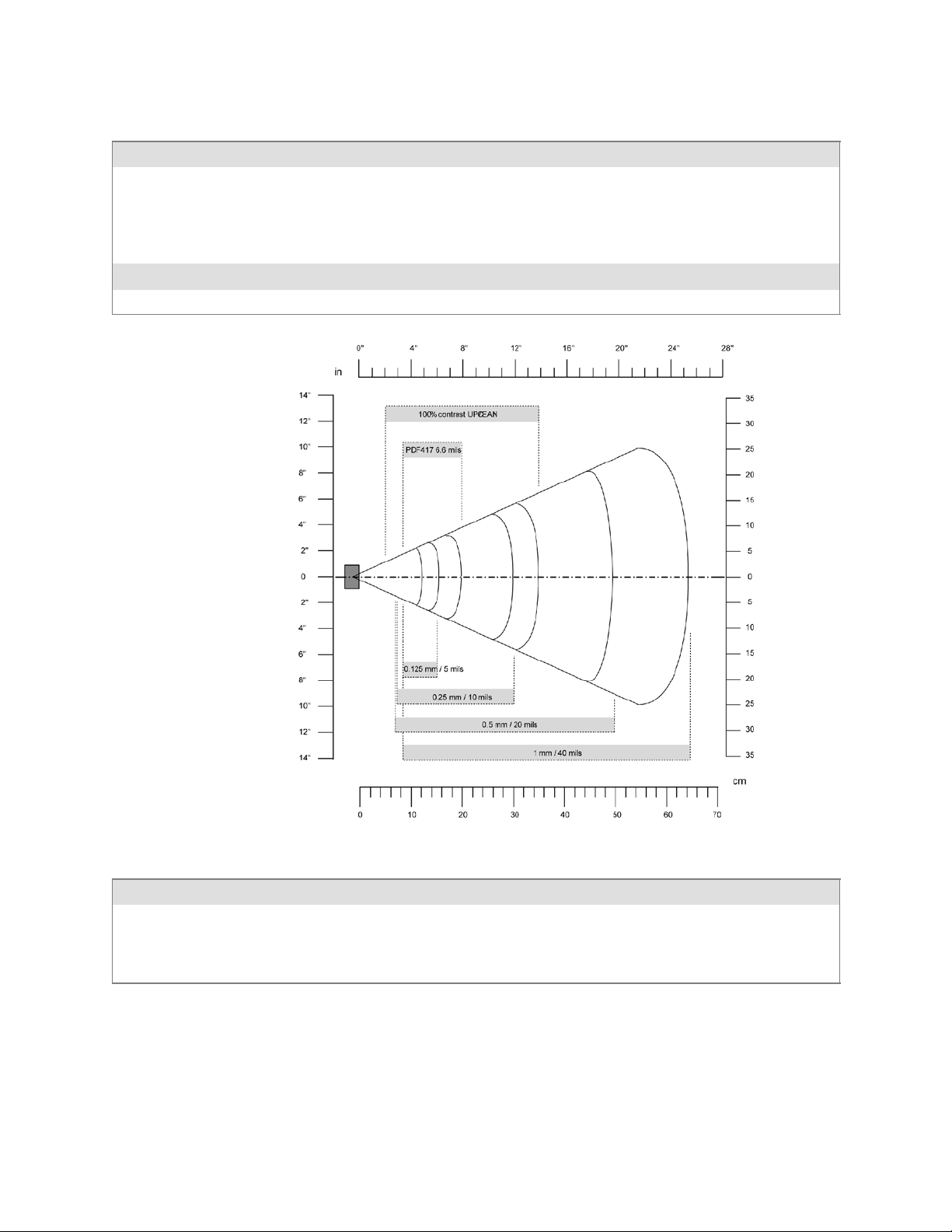
6 Scanner Support—Chapter
EL10 Minimum Guaranteed Reading Distances with 0.25” Setbacks
Symbology Density Minimum Distance Maximum Distance
Code 39 0.1 mm/ 4 mil
0.125 mm/ 5 mil
0.25 mm/ 10 mil
0.5 mm/ 20 mil
1 mm/ 40 mil
UPC/EAN 0.33 mm/ 13 mil 5.46 cm/ 2.15” 34.42 cm/ 13.55”
PDF417 0.17 mm/ 6.6 mil 7.75 cm/ 3.05” 19.43 cm/ 7.65”
8.51 cm/ 3.35”
7.75 cm/ 3.05”
6.99 cm/ 2.75”
6.48 cm/ 2.55”
7.75 cm/ 3.05”
12.30 cm/ 4.45”
14.35 cm/ 5.65”
29.34 cm/ 11.55”
50.17 cm/ 19.75”
63.37 cm/ 24.95”
EL11 Minimum Reading Distances with 0.04” Setbacks
Symbology Density Minimum Distance Maximum Distance
0.1 mm/ 4 mil
0.125 mm/ 5 mil
0.33 mm/ 13 mil (EAN)
1 mm/ 40 mil
8.79 cm/ 3.46”
8.28 cm/ 3.26”
5.49 cm/ 2.16”
9.55 cm/ 3.86”
11.84 cm/ 4.66”
14.48 cm/ 5.86”
34.95 cm/ 13.76”
63.91 cm/ 25.16”
175700 Series Color Mobile Computer User’s Manual

Scanner SupportChapter —6
EV10 Minimum Reading Distances with 0.04” Setbacks
Symbology Bar Code Content Density Minimum Distance Maximum Distance
Code 39 RESO 0.100 MM
R 0.125 MM
0.25
0.5
R1MM
UPC/EAN 120010010100 0.33 mm/ 13 mil 4.98 cm/ 1.96” 25.81 cm/ 10.16”
PDF417 10 mil
15 mil
0.1 mm/ 4 mil
0.125 mm/ 5 mil
0.25 mm/ 10 mil
0.5 mm/ 20 mil
1 mm/ 40 mil
0.254 mm/ 10 mil
0.381 mm/ 15 mil
10.8 cm/ 4.26”
9.80 cm/ 3.86”
5.99 cm/ 2.36”
3.96 cm/ 1.56”
7.53 cm/ 2.96”
9.80 cm/ 3.86”
7.77 cm/ 3.06”
13.87 cm/ 5.46”
16.92 cm/ 6.66”
23.77 cm/ 9.36”
30.89 cm/ 12.16”
39.78 cm/ 15.66”
16.92 cm/ 6.66”
18.95 cm/ 7.46”
2D Area Imager Reading Distances with 0.04” Setbacks
Symbology Density Near Distance Far Distance
MaxiCode 35 mil 4.98 cm/ 1.96” 33.92 cm/ 12.96”
Data Matrix 15 mil 9.30 cm/ 3.66” 16.41 cm/ 6.46”
PDF417 10 mil
8mil
6.6 mil
Code 39 15 mil
10 mil
8mil
UPC 13 mil 6.25 cm/ 2.46” 31.65 cm/ 12.46”
176 700 Series Color Mobile Computer User’s Manual
7.77 cm/ 3.06”
8.28 cm/ 3.26”
11.33 cm/ 4.46”
5.23 cm/ 2.06”
8.03 cm/ 3.16”
8.79 cm/ 3.46”
22.76 cm/ 8.96”
20.22 cm/ 7.96”
15.77 cm/ 6.21”
29.87 cm/ 11.76”
23.27 cm/ 9.16”
19.20 cm/ 7.56”

Tethered Scanners
The Intermec Tethered Scanner feature allows Automatic Data Collection
(ADC) by accepting data from the COM1 port and wedging it into the
keyboard interface. You can enable or disable this feature from the Today
screen on the 700 Color Computer.
Configuring the Tethered Scanner
Before you configure your tethered scanner, adjust its settings using the
Intermec Settings applet. Information about the settings you can configure
with this applet is described in the Intermec Computer Command Reference
Manual. The online manual is available from the Intermec web site at
www.intermec.com.
1 Connect your tethered scanner to the tethered scanner port.
2 From the 700 Color Computer, tap Start > Settings >theSystem tab >
the Intermec Settings icon.
6 Scanner Support—Chapter
3 Tap Data Collection, then tap (+) to expand Dock Tethered Scanner.
177700 Series Color Mobile Computer User’s Manual

Scanner SupportChapter —6
4 Tap (+) to expand Scanner Settings,tapScanner model,thenenterthe
applicable scanner, such as “1551E” or “1553.”
5 Make sure a scanner is properly connected to your 700 Computer, tap
to check Enable scanner port,thentapFile > Save Settings from the
bottom of the screen. These changes take several moments to reset.
1551E or 1553 Selected for Scanner Model
When “1551E” or “1553” is selected from the Scanner model option (see
step 4 above), and the port state is already enabled (see step 5),theprocess
will take several moments to reset. When 1551E or 1553 is successfully
connected during this step, the unit will emit some beeps. Here, the terminal is initializing the scanner at 9600 for the baud rate, 7 data bits, even
parity, and 2 stop bits and synchronizing the terminal’s configuration with
the attached scanner.
With “1551E” or “1553” selected, Symbologies, Symbology Options,
Hardware Trigger, and Scanner Port settings are configured from the Intermec Settings applet. See the the Intermec Computer Command Reference
178 700 Series Color Mobile Computer User’s Manual

6 Scanner Support—Chapter
Manual, available from the Intermec web site at www.intermec.com, for
more information about each enabled option.
ASCII S elected for Scanner Model
To send data coming into the 700 Color Computer through the COM1
port from an external input device, as keyboard data to an application on
the desktop, do the following:
1 Enter “ASCII” as the Scanner model option.
2 Tap to check Enable scanner port.
3 Tap File > Save Settings from the bottom of the screen, or tap Yes
when prompted to refresh the scanner settings.
With “ASCII” selected, Symbology Options, Hardware Trigger, and Scanner Port settings are configured from the Intermec Settings applet. See the
the Intermec Computer Command Reference Manual, available from the Intermec web site at www.intermec.com, for more information about each
enabled option.
Note: When selecting either the 1551E or the 1553 Scanner or enabling
the scanner port for these scanners, the 700 Computer tries to communicate with the attached scanner. If the scanner is not powered, if the cable is
not connected properly, the wrong cable is used, or if the scanner firmware
is older than 2.0, and the “Failed to save one or more settings” message
appears, then this step failed.
This process can take time as the terminal is going through a group of
RS-232 settings to communicate with the scanner. After successful communicated with the scanner (about eight beeps are generated), it initializes
the scanner with the 700 Computer’s current settings. This process might
generate a series of beeps pending on the firmware version installed in the
scanner. These beeps are suppressed in firmware versions 2.08 or greater.
Troubleshooting the 1551E/1553 Tethered Scanner
Do the following to troubleshoot your 1551E/1553 Tethered Scanner:
1 Ensure the correct cable is used for the scanner on the tethered scanner
port. Note the 700 Computer cannot supply power to the scanner.
2 Perform a quick test to determine whether the connection is good.
Temporary select the scanner model as “ASCII,” then enable the scanner port state. Go to a command prompt or a notepad and scan a data
label. If a label is wedged into the command prompt or notepad, then
the connection is good.
3 If step 2 passes, reset the scanner configurations to their defaults (scan
the Reset Factory Defaults label on the next page) to prevent miscommunication, then reenable the scanner port state.
4 If step 2 fails, then the firmware installed in the tethered scanner may be
older than version 2.0. Upgrade your scanner firmware.
179700 Series Color Mobile Computer User’s Manual

Scanner SupportChapter —6
Reset Factory Defaults
Scan the EasySet software bar code label “Reset Factory Default” to restore
all of your scanner’s configurations to their factory defaults. When this
command label is scanned, reinitialize the tethered scanner (such as disable
the scanner port state, then enable it) on the 700 Computer. Otherwise,
the online configuration and scanning on the 700 Computer are not functional. In general, scan this label only to initially reset the scanner.
Do not scan EasySet command labels to change the following settings:
S Symbologies code mark S Code 128, EAN29 Identifier
S Preamble and Postamble S Enable/Disable symbologies
S Symbology ID transmit option
In some cases, scanning EasySet Command labels cause the current setting
on the user interface to be out of sync with the scanner settings. However,
in some cases, scanning these labels does corrupt scanned data.
The “Open COMx error: 0x00000037” message appears if the COM port
cannot open due to another application using the port. Disable that application to free up the COM1 port before you can enable the scanner. “x”
is the COM port number, such as 1, 2, or 3.
Tethered Scanner Supported Symbologies
The user interface may allow configuration of PDF417, Micro PDF417,
RSS, and Codablock bar code symbologies. However, these symbologies
are dependant on what scanner models and firmware versions are in use.
See the following table for a guideline on each supported symbology:
You can use a generic ASCII scanner with the 700 Color Computer.
Pending on the scanner, linear symbologies such as Code39, should decode correctly. However, 2D symbologies such as PDF417 may not decode correctly.
Symbologies 1551E 1553
Code39 XX
UPC/EAN X X
Code 128 XX
Interleaved 2 of 5 X X
Code 93 XX
Codabar X X
Code 2 of 5 XX
MSI X X
Plessey XX
Code 11 X X
Matrix 2 of 5 XX
Telepen X X
180 700 Series Color Mobile Computer User’s Manual

6 Scanner Support—Chapter
15531551ESymbologies
PDF417 Available in 1551 0808 PDF
Micro PDF417 Available in 1551 0808 PDF, Sxxp217_ or later
MaxiCode
Data Matrix
QR Code
RSS 14 F/w version 2.15 or later F/w version 2.15 or later
RSS Limited F/w version 2.15 or later F/w version 2.15 or later
RSS Expanded F/w version 2.15 or later F/w ve rsion 2.15 or later
Codablock A Available in 1551 0808 PDF
Codablock F Available in 1551 0808 PDF
UCC Composite
Attached RFID Readers
Note: The 700 Color Computer currently supports only the IP4 Intellitag
Portable RFID Reader, a trigger handle accessory that lets you hold your
700 Color Computer like a reader or scanner. Contact your Intermec r epresentative for more information.
Radio frequency identification (RFID) systems evolved as a way to provide
all the benefits of visual scanning systems, while o vercoming many of their
limitations. Radio frequency (RF) describes electromagnetic waves in the
10 kHz to 10 GHz range. Electronic identification (ID) systems transfer
data messages from an object to be identified to a data management system. RFID systems use radio frequency to transfer data between an item
being tracked and a reader/writer. It is a fast, automatic identification
technology.
More information about RFID and the IP4 Reader are in the following
Intermec publications. PDFs of these publications are available fr om the
Intermec web site at www.intermec.com.
S Basic Reader Interface Programmer’s Reference Manual
(P/N: 937-000-001)
S Intermec RFID System Manual (P/N: 936-000-001)
S IP4 Handheld Reader Instructions (P/N: 943-002-002)
S IP4 Handheld Reader Manual Supplement (P/N: 933-000-001)
Reading RFID Tags with the Virtual Wedge
The virtual wedge is a Data Collection services feature that enters bar code
and RFID tag data into a software application as if it were typed at the
keypad. This section explains how to configure the 700 Color Computer
to read RFID tags through the virtual wedge. Contact your Intermec representative for more information about the virtual wedge.
181700 Series Color Mobile Computer User’s Manual

Scanner SupportChapter —6
Do the following to configure your virtual wedge to do RFID tags.
S Configure at least one scan button on the 700 Color Computer to trig-
ger RFID (gotothenextparagraph).
S Disable power to Bluetooth (go to page 183 for instructions).
S Enable the IP4 Reader (go to page 184 for instructions).
Use the Intermec Settings applet to configure at least one scan button. Information about the settings you can configure with this applet is described in the Intermec Computer Command Reference Manual.Theonline
manual is available from the Intermec web site at www.intermec.com.
1 From the 700 Color Computer, tap Start > Settings >theSystem tab >
the Intermec Settings icon > the Device Settings option, then tap (+) to
expand the Keypad option.
2 Tap (+) to expand Scan Button Remapping, then tap (+) to expand any
of the Handle Trigger,theLeft Scan Button,ortheRight Scan Button
options. Note that the Handle Trigger option is for the IP4 Reader.
182 700 Series Color Mobile Computer User’s Manual

6 Scanner Support—Chapter
3 Select RFID to change the trigger from the scanner to RFID, then select
File > Save Settings.
4 Go to the next paragraph to disable power to Bluetooth.
5 Go to page 184 to enable the IP4 Reader.
Disable Power to Bluetooth
Note: Before you configure your attached IP4 Reader, make sure Bluetooth is disabled on your 700 Color Computer.
1 Tap Start > Settings >theConnections tab>theBluetooth icon.
2 Check whether Off isselected.Ifnot,thencheckOff.Waitmomentari-
ly for Bluetooth to turn off, then click ok to close the Bluetooth applet.
183700 Series Color Mobile Computer User’s Manual

Scanner SupportChapter —6
Configure the Reader Using Intermec Settings
You should also adjust its settings using the Intermec Settings applet. Information about the settings you can configure with this applet is described in the Intermec Computer Command Reference Manual.Theonline
manual is available from the Intermec web site at www.intermec.com.
1 Connect your reader to the reader port.
1 From the 700 Color Computer, tap Start > Settings >theSystem tab >
the Intermec Settings icon > the RFID option.
2 Tap (+) to expand Reader 1 and ensure Reader Model shows “IP4” as
the model of choice. If not, then tap Reader Model, tap its drop-down,
then select “IP4.”
184 700 Series Color Mobile Computer User’s Manual

6 Scanner Support—Chapter
3 Under the Reader option, check Enable Reader to enable the attached
reader.
Once the IP4 reader is configured using the Intermec Settings applet, applications can access the IP4 Reader using the Basic Reader Interface (BRI)
protocol on the 700 Color TCP port “2189.”
185700 Series Color Mobile Computer User’s Manual

Scanner SupportChapter —6
186 700 Series Color Mobile Computer User’s Manual

Programming
7
The following programming information pertains to the 700 Series Color
Mobile Computer:
S Creating CAB Files (page 188)
S Customization and Lockdown (page 202)
S FTP Server (page 203)
S Kernel I/O Control Functions (page 210)
S Network Selection APIs (page 221)
S Notifications (page 221)
S Reboot Functions (page 222)
S Remapping the Keypad (page 223)
Note: “700 Color” pertains to 730, 740, 741, 750, 751, 760, and 761
Computers unless otherwise noted.
187700 Series Color Mobile Computer User’s Manual

ProgrammingChapter —7
Creating CAB Files
The Windows CE operating system uses a .CAB file to install an application on a Windows CE-based device. A .CAB file is composed of multiple
files that are compressed into one file. Compressing multiple files into one
file provides the following benefits:
S All application files are present.
S A partial installation is prevented.
S The application can be installed from several sources, such as a desktop
computer or a Web site.
Use the CAB Wizard application (CABWIZ.EXE) to generate a .CAB file
for your application.
Creating Device-Specific CAB Files
Do the following to create a device-specific .CAB file for an application, in
the order provided:
1 Create an .INF file with Windows CE-specific modifications (page
2 Optional Create a SETUP.DLL file to provide custom control of the
3 Use the CAB Wizard to create the .CAB file, using the .INF file, the
Creating an .INF File
An .INF file specifies information about an application for the CAB Wizard. Below are the sections of an .INF file:
[Version]
This specifies the creator of the file, version, and other relevant information.
Required? Yes
S Signature:“signature_name”
S Provider:“INF_creator”
188).
installation process (page 197).
optional SETUP.DLL file, and the device-specific application files as
parameters (page 201).
“$Windows NT$”
The company name of the application, such as “Microsoft.”
S CESignature
“$Windows CE$”
Example
[Version]
Signature = “$Windows NT$”
Provider = “Intermec”
CESignature = “$Windows CE$”
188 700 Series Color Mobile Computer User’s Manual

[CEStrings]
This specifies string substitutions for the application name and the default
installation directory.
Required? Yes
S AppName: app_name
S InstallDir: default_install_dir
Example
[CEStrings]
AppName=“Game Pack”
InstallDir=%CE1%\%AppName%
[Strings]
This section is optional and defines one or more string keys. A string key
represents a string of printable characters.
Programming—Chapter 7
Name of the application. Other instances of %AppName% in the .INF
file are replaced with this string value, such as RP32.
Default installation directory on the device. Other instances of %InstallDir% in the .INF file are replaced with this string value. Example:
\SDMMC_Disk\%AppName%
Required? No
S string_key: value
Example
[Strings]
reg_path = Software\Intermec\My Test App
[CEDevice]
Describes the platform for the targeted application. All keys are optional.
If a key is nonexistent or has no data, Windows CE does not perform any
checking except the UnsupportedPlatforms.IftheUnsupportedPlatforms key
exists but no data, the previous value is not overridden.
Required? Yes
S ProcessorType : processor_type
S UnsupportedPlatforms: platform_family_name
String consisting of letters, digits, or other printable characters. Enclose
value in double quotation marks ““”” if corresponding string key is used
in an item requiring double quotation marks. No string_keys is okay.
The value that is returned by SYSTEMINFO.dwProcessorType.For
example, the value for the ARM CPU is 2577
This lists known unsupported platform family names. If the name
specified in the [CEDevice.xxx] section is different from that in the
[CEDevice] section, both platform_family_name values are unsupported
for the microprocessor specified by xxx. That is, the list of unsupported
platform family names is appended to the previous list of unsupported
names. Application Manager will not display the application for an
unsupported platform. Also, a user will be warned during the setup
process if the .CAB file is copied to an unsupported device.
189700 Series Color Mobile Computer User’s Manual

ProgrammingChapter —7
Example
[CEDevice]
UnsupportedPlatforms = pltfrm1 ; pltfrm1 is unsupported
[CEDevice.SH3]
UnsupportedPlatforms = ; pltfrm1 is still unsupported
S VersionMin: minor_version
Numeric value returned by OSVERSIONINFO.dwVersionMinor. The
.CAB file is valid for the currently connected device if the version of
this device is greater than or equal to VersionMin.
S VersionMax: major_version
Numeric value returned by OSVERSIONINFO.dwVersionMajor. The
.CAB file is valid for the currently connected device if the version of
this device is less than or equal to VersionMax.
S BuildMin: build_number
Numeric value returned by OSVERSIONINFO.dwBuildNumber. The
.CAB file is valid for the currently connected device if the version of
this device is greater than or equal to BuildMin.
S BuildMax: build_number
Numeric value returned by OSVERSIONINFO.dwBuildNumber. The
.CAB file is valid for the currently connected device if the version of
this device is less than or equal to BuildMax.
Example
The following code example shows three [CEDevice] sections: one that
gives basic information for any CPU and two that are specific to the SH3
and the MIPS microprocessors.
[CEDevice] ; A “template” for all platforms
UnsupportedPlatforms = pltfrm1 ; Does not support pltfrm1
; The following specifies version 1.0 devices only.
VersionMin = 1.0
VersionMax = 1.0
[CEDevice.ARM] ; Inherits all [CEDevice] settings
; This will create a .CAB file specific to ARM devices.
ProcessorType = 2577 ; ARM .cab file is valid for ARM microprocessors.
UnsupportedPlatforms = ; pltfrm1 is still unsupported
; The following overrides the version settings so that no version checking is
performed.
VersionMin =
VersionMax =
[CEDevice.MIPS] ; Inherits all [CEDevice] settings
; This will create a .CAB file specific to “MIPS” devices.
ProcessorType = 4000 ; MIPS .CAB file is valid for MIPS
microprocessor.
UnsupportedPlatforms =pltfrm2 ; pltfrm1, pltfrm2 unsupported for MIPs .CAB
file.
Note: To cre ate the two CPU-specific .CAB files f or the SETUP.INF file
in the previous example, run the CAB Wizard with the “/cpu arm mips”
parameter.
190 700 Series Color Mobile Computer User’s Manual

[DefaultInstall]
This describes the default installation of your application. Note that under
this section, you will list items expanded upon later in this description.
Required? Yes
S Copyfiles: copyfile_list_section
S AddReg: add_registry_section
S CEShortcuts: shortcut_list_section
S CESetupDLL: setup_DLL
Programming—Chapter 7
Maps to files defined later in the .INF file, such as Files.App, Files.Font,
and Files.Bitmaps.
Example: RegSettings.All
String that identifies one more section that defines shortcuts to a file, as
defined in the [CEShortcuts] section.
Optimal string that specifies a SETUP.DLL file. It is written by the Independent Software Vendor (ISV) and contains customized functions
for operations during installation and removal of the application. The
file must be specified in the [SourceDisksFiles] section.
S CESelfRegister: self_reg_DLL_filename
Example
[DefaultInstall]
AddReg = RegSettings.All
CEShortcuts = Shortcuts.All
[SourceDiskNames]
This section describes the name and path of the disk on which your application resides.
Required? Yes
S disk_ordinal: disk_label,,path
S CESignature: “$Windows CE$”
String that identifies files that self-register by exporting the DllRegisterServer and DllUnregisterServer Component Object Model (COM)
functions. Specify these files in the [SourceDiskFiles] section. During
installation, if installation on the device fails to call the file’s exported
DllRegisterServer function, the file’s exported DllUnregisterServer
function will not be called during removal.
1=,“App files” , C:\Appsoft\RP32\...
2=,“Font files”,,C:\RpTools\...
3=,“CE Tools” ,,C:\windows ce tools...
Example
[SourceDisksNames] ; Required section
1 = ,“Common files”,,C:\app\common ; Using an absolute path
[SourceDisksNames.SH3]
2 = ,“SH3 files”,,sh3 ; Using a relative path
[SourceDisksNames.MIPS]
2 = ,“MIPS files”,,mips ; Using a relative path
191700 Series Color Mobile Computer User’s Manual

ProgrammingChapter —7
[SourceDiskFiles]
This describes the name and path of the files in which your application
resides.
Required? Yes
S filename: disk_number[,subdir]
RPM.EXE = 1,c:\appsoft\...
WCESTART.INI = 1
RPMCE212.INI = 1
TAHOMA.TTF = 2
Note: [,subdir] is relative to the location of the INF file.
Example
[SourceDisksFiles] ; Required section
begin.wav = 1
end.wav = 1
sample.hlp = 1
[SourceDisksFiles.SH3]
sample.exe = 2 ; Uses the SourceDisksNames.SH3 identification of 2.
[SourceDisksFiles.MIPS]
sample.exe = 2 ; Uses the SourceDisksNames.MIPS identification of 2.
[DestinationDirs]
This describes the names and paths of the destination directories for the
application on the target device. Note Windows CE does not support directo-
ry identifiers.
Required? Yes
S file_list_section: 0,subdir
String that identifies the destination directory. The following list shows
the string substitutions supported by Windows CE. Use these only for
the beginning of the path. \
%CE1% \Program Files
%CE2% \Windows
%CE3% \My Documents
%CE4% \Windows\Startup
%CE5% \My Documents
%CE6% \Program Files\Accessories
%CE7% \Program Files\Communication
%CE8% \Program Files\Games
%CE9% \Program Files\Pocket Outlook
%CE10% \Program Files\Office
%CE11% \Windows\Start Menu\Programs
%CE12% \Windows\Start Menu\Programs\Accessories
%CE13% \Windows\Start Menu\Programs\Communications
%CE14% \Windows\Start Menu\Programs\Games
%CE15% \Windows\Fonts
%CE16% \Windows\Recent
%CE17% \Windows\Start Menu
%InstallDir%
192 700 Series Color Mobile Computer User’s Manual

Contains the path to the target directory selected during installation. It
is declared in the [CEStrings] section
%AppName%
Contains the application name defined in the [CEStrings] section.
Example
[DestinationDirs]
Files.Common = 0,%CE1%\My Subdir ; \Program Files\My Subdir
Files.Shared = 0,%CE2% ; \Windows
[CopyFiles]
This section, under the [DefaultInstall] section, describes the default files
to copy to the target device. Within the [DefaultInstall] section, files were
listed that must be defined elsewhere in the INF file. This section identifies that mapping and may contain flags.
Required? Yes
S copyfile_list_section: destination_filename,[source_filename]
The source_filename parameter is optional if it is the same as destina-
tion_filename.
Programming—Chapter 7
S copyfile_list_section: flags
The numeric value that specifies an action to be done while copying files. The following table shows values supported by Windows CE.
Flag Value Description
COPYFLG_WARN_IF_SKIP 0x00000001 Warn use r if skipping a file is attempted after error.
COPYFLG_NOSKIP 0x00000002 Do not allow a user to skip copying a file.
COPYFLG_NO_OVERWRITE 0x00000010 D o not overwrite files in destination directory.
COPYFLG_REPLACEONLY 0x00000400 Copy the source file to the destination directory only if the
file is already in the destination directory.
CE_COPYFLG_NO_DATE_DIALOG 0x20000000 Do not copy files if the target file is ne wer.
CE_COPYFLG_NODATECHECK 0x40000000 Ignore date while overwriting the target file.
CE_COPYFLG_SHARED 0x80000000 Create a reference when a shared DLL is counted.
Example
[DefaultInstall.SH3]
CopyFiles = Files.Common, Files.SH3
[DefaultInstall.MIPS]
CopyFiles = Files.Common, Files.MIPS
[AddReg]
This section, under the [DefaultInstall] section, is optional and describes
the keys and values that the .CAB file adds to the device registry. Within
the [DefaultInstall] section, a reference may have been made to this
section, such as “AddReg=RegSettings.All”. This section defines the
options for that setting.
Required? No
193700 Series Color Mobile Computer User’s Manual

ProgrammingChapter —7
S add_registry_section: registry_root_string
String that specifies the registry root location. The following list shows
the values supported by Windows CE.
S HKCR Same as HKEY_CLASSES_ROOT
S HKCU Same as HKEY_CURRENT_USER
S HKLM Same as HKEY_LOCAL_MACHINE
S add_registry_section: value_name
Registry value name. If empty, the “default” registry value name is used.
S add_registry_section: flags
Numeric value that specifies information about the registry key. The
following table shows the values that are supported by Window CE.
Flag Value Description
FLG_ADDREG_NOCLOBBER 0x00000002 If the registry key exists, do not overwrite it. Can be used
with any of the other flags in this table.
FLG_ADDREG_TYPE_SZ 0x00000000 REG_SZ registry data type.
FLG_ADDREG_TYPE_MULTI_SZ 0x00010000 REG_MULTI_SZ registry data type. Value field that follows
can be a list of strings separated by commas.
FLG_ADDREG_TYPE_BINARY 0x00000001 REG_BINARY registry data type. Value field that follows
must be a list of numeric values separated by commas, one
byte per field, and must not use the 0x hexadecimal prefix.
FLG_ADDREG_TYPE_DWORD 0x00010001 REG_DWORD data type. The noncompatible format in the
Win32 Setup .INF documentation is supported.
Example
AddReg = RegSettings.All
[RegSettings.All]
HKLM,%reg_path%,,0x00000000,alpha ; <default> = “alpha”
HKLM,%reg_path%,test,0x00010001,3 ; Test = 3
HKLM,%reg_path%\new,another,0x00010001,6 ; New\another = 6
[CEShortCuts]
This section, a Windows CE-specific section under the [DefaultInstall]
section, is optional and describes the shortcuts that the installation application creates on the device. Within the [DefaultInstall] section, a reference
may have been made to this section, such as “ShortCuts.All”. This section
defines the options for that setting.
Required? No
S shortcut_list_section: shortcut_filename
String that identifies the shortcut name. It does not require the .LNK
extension.
S shortcut_list_section: shortcut_type_flag
Numeric value. Zero or empty represents a shortcut to a file; any nonzero numeric value represents a shortcut to a folder.
194 700 Series Color Mobile Computer User’s Manual

Programming—Chapter 7
S shortcut_list_section: target_file_path
String value that specifies the destination location. Use the target file
name for a file, such as MyApp.exe, that must be defined in a file copy
list. For a path, use a file_list_section name defined in the [Destination-
Dirs] section, such as DefaultDestDir,orthe%InstallDir% string.
S shortcut_list_section: standard_destination_path
Optional string value. A standard %CEx% path or %InstallDir%.Ifno
value is specified, the shortcut_list_section name of the current section or
the DefaultDestDir value from the [DestinationDirs] section is used.
Example
CEShortcuts = Shortcuts.All
[Shortcuts.All]
Sample App,0,sample.exe ; Uses the path in DestinationDirs. Sample
App,0,sample.exe,%InstallDir% ; The path is explicitly specified.
Sample .INF File
[Version] ; Required section
Signature = “$Windows NT$”
Provider = “Intermec Technologies Corporation”
CESignature = “$Windows CE$”
;[CEDevice]
;ProcessorType =
[DefaultInstall] ; Required section
CopyFiles = Files.App, Files.Fonts, Files.BitMaps, Files.Intl,
Files.TelecomNcsCE, Files.Windows, Files.Import, Files.Export, Files.Work,
Files.Database, Files.WinCE AddReg = RegSettings.All ;CEShortcuts =
Shortcuts.All
[SourceDisksNames] ; Required section
1 = ,“App files” ,,c:\appsoft\...
2 = ,”Font files” ,,c:\WinNT\Fonts
3 = ,”CE Tools” ,,c:\windows ce tools\wce400\700ie\mfc\lib\x86
[SourceDisksFiles] ; Required section
rpm.exe = 1,C:\Appsoft\program\wce400\WCEX86Rel700
wcestart.ini = 1
rpmce212.ini = 1
intermec.bmp = 1
rpmlogo.bmp = 1
rpmname.bmp = 1
import.bmp = 1
export.bmp = 1
clock.bmp = 1
printer.bmp = 1
filecopy.bmp = 1
readme.txt = 1
lang_eng.bin = 1
rpmdata.dbd = 1,database\wce1
tahoma.ttf = 2
mfcce212.dll = 3
olece212.dll = 3
olece211.dll = 1,c:\windows ce tools\wce400\NMSD61102.11\mfc\lib\x86
rdm45wce.dll = 1,c:\rptools\rdm45wce\4_50\lib\wce400\wcex86rel
picfmt.dll = 1,c:\rptools\picfmt\1_00\wce400\wcex86rel6110
195700 Series Color Mobile Computer User’s Manual

ProgrammingChapter —7
fmtctrl.dll = 1,c:\rptools\fmtctrl\1_00\wce400\wcex86rel6110
ugrid.dll = 1,c:\rptools\ugrid\1_00\wce400\wcex86rel6110
simple.dll = 1,c:\rptools\pspbm0c\1_00\wce400\wcex86rel
psink.dll = 1,c:\rptools\psink\1_00\wce400\WCEX86RelMinDependency
pslpwce.dll =1,c:\rptools\pslpm0c\1_00\wce400\WCEX86RelMinDependency
npcpport.dll = 1,c:\rptools\cedk\212_03\installable drivers\printer\npcp
;dexcom.dll = 1,c:\rptools\psdxm0c\1_00\x86
ncsce.exe = 1,c:\rptools\ncsce\1_04
nrinet.dll = 1,c:\rptools\ncsce\1_04
[DestinationDirs] ; Required section
;Shortcuts.All = 0,%CE3% ; \Windows\Desktop
Files.App = 0,%InstallDir%
Files.DataBase = 0,%InstallDir%\DataBase
Files.BitMaps = 0,%InstallDir%\Bitmaps
Files.Fonts = 0,%InstallDir%\Fonts
Files.Intl = 0,%InstallDir%\Intl
Files.TelecomNcsCE = 0,%InstallDir%\Telecom\NcsCE
Files.Windows = 0,%InstallDir%\Windows
Files.Import = 0,%InstallDir%\Import
Files.Export = 0,%InstallDir%\Export
Files.Work = 0,%InstallDir%\Work
Files.WinCE = 0,\storage_card\wince
[CEStrings] ; Required section
AppName = Rp32
InstallDir = \storage_card\%AppName%
[Strings] ; Optional section
;[Shortcuts.All]
;Sample App,0,sample.exe ; Uses the path in DestinationDirs.
;Sample App,0,sample.exe,%InstallDir% ; The path is explicitly specified.
[Files.App]
rpm.exe,,,0
rpm.ini,rpmce212.ini,,0
mfcce212.dll,,,0
olece212.dll,,,0
olece211.dll,,,0
rdm45wce.dll,,,0
picfmt.dll,,,0
fmtctrl.dll,,,0
ugrid.dll,,,0
simple.dll,,,0
psink.dll,,,0
pslpwce.dll,,,0
npcpport.dll,,,0
;dexcom.dll,,,0
[Files.DataBase]
rpmdata.dbd,,,0
[Files.Fonts]
tahoma.ttf,,,0
[Files.BitMaps]
intermec.bmp,,,0
rpmlogo.bmp,,,0
rpmname.bmp,,,0
196 700 Series Color Mobile Computer User’s Manual

import.bmp,,,0
export.bmp,,,0
clock.bmp,,,0
printer.bmp,,,0
filecopy.bmp,,,0
[Files.Intl]
lang_eng.bin,,,0
[Files.TelecomNcsCE]
ncsce.exe,,,0
nrinet.dll,,,0
[Files.Windows]
readme.txt,,,0
[Files.Import]
readme.txt,,,0
[Files.Export]
readme.txt,,,0
[Files.Work]
readme.txt,,,0
Programming—Chapter 7
[Files.WinCE]
wcestart.ini,,,0
[RegSettings.All]
HKLM,”SOFTWARE\Microsoft\Shell\AutoHide”,,0x00010001,1
; Autohide the taskbar HKLM,”SOFTWARE\Microsoft\Shell\OnTop”,,0x00010001,0
; Shell is not on top
HKLM,”SOFTWARE\Microsoft\Clock”,SHOW_CLOCK,0x00010001,0
; Clock is not on taskbar
Using Installation Functions in SETUP.DLL
SETUP.DLL is an optional file that enables you to perform custom operations during installation and removal of your application. The following
list shows the functions that are exported by SETUP.DLL.
Install_Init Called before installation begins. Use this function to check the application version when reinstal-
ling an application and to determine if a dependent application is present.
Install_Exit Called after installation is complete. Use th is function to h andle errors that occur during applica-
tion installation.
Uninstall_Init Called before the removal process begins. Use this function to close the application, if the applica-
tion is running.
Uninstall_Exit Called after the removal process is complete. Use this function to save database information to a
file and delete the database and to tell the user where the user data files are stored and how to reinstall the application.
Note;Use[DefaultInstall] > CESelfRegister (page 191) in the .INF file to
point to SETUP.DLL.
197700 Series Color Mobile Computer User’s Manual

ProgrammingChapter —7
After the CAB File Extraction
Cab files that need to cause a warm reset after cab extraction will need to
create the __RESETMEPLEASE__.TXT file in the “\Windows” directory.
The preferred method to create this file is within the DllMain portion of
the SETUP.DLL file. It looks like this:
#include <windows.h>
#include <Tlhelp32.h>
#include <winioctl.h>
#include <ce_setup.h> // in the public SDK dir
#define IOCTL_TERMINAL_RESET CTL_CODE (FILE_DEVICE_UNKNOWN,FILE_ANY_ACCESS,
2050, METHOD_NEITHER)
BOOL APIENTRY DllMain( HANDLE h, DWORD reason, LPVOID lpReserved )
{
return TRUE;
} // DllMain
//************************************************************************
// $DOCBEGIN$
// BOOL IsProcessRunning( TCHAR * pname );
//
// Description: Get process table snapshot, look for pname running.
//
// Arguments: pname - pointer to name of program to look for.
// for example, app.exe.
//
// Returns: TRUE - process is running.
// FALSE - process is not running.
// $DOCEND$
//************************************************************************
BOOL IsProcessRunning( TCHAR * pname )
{
HANDLE hProcList;
PROCESSENTRY32 peProcess;
DWORD thDeviceProcessID;
TCHAR lpname[MAX_PATH];
if ( !pname || !*pname ) return FALSE;
_tcscpy( lpname, pname );
_tcslwr( lpname );
hProcList = CreateToolhelp32Snapshot( TH32CS_SNAPPROCESS, 0 );
if ( hProcList == INVALID_HANDLE_VALUE ) {
return FALSE;
} // end if
memset( &peProcess, 0, sizeof(peProcess) );
peProcess.dwSize = sizeof(peProcess);
if ( !Process32First( hProcList, &peProcess)){
CloseToolhelp32Snapshot( hProcList );
return FALSE;
} // end if
198 700 Series Color Mobile Computer User’s Manual

Programming—Chapter 7
thDeviceProcessID = 0;
do {
_tcslwr( peProcess.szExeFile );
if ( _tcsstr( peProcess.szExeFile, lpname)){
thDeviceProcessID = peProcess.th32ProcessID;
break;
} // end if
} while ( Process32Next( hProcList, &peProcess ) );
if ( ( GetLastError() == ERROR_NO_MORE_FILES ) && ( thDeviceProcessID == 0
)){
CloseToolhelp32Snapshot( hProcList );
return FALSE;
} // end if
CloseToolhelp32Snapshot( hProcList );
return TRUE;
} // IsProcessRunning
codeINSTALL_INIT Install_Init(
HWND hwndParent,
BOOL fFirstCall,
BOOL fPreviouslyInstalled,
LPCTSTR pszInstallDir )
{
return codeINSTALL_INIT_CONTINUE;
}
codeINSTALL_EXIT Install_Exit (
HWND hwndParent,
LPCTSTR pszInstallDir,
WORD cFailedDirs,
WORD cFailedFiles,
WORD cFailedRegKeys,
WORD cFailedRegVals,
WORD cFailedShortcuts )
{
HANDLE h;
TCHAR srcfile[MAX_PATH];
TCHAR dstfile[MAX_PATH];
if (cFailedDirs || cFailedFiles || cFailedRegKeys ||
cFailedRegVals || cFailedShortcuts)
return codeINSTALL_EXIT_UNINSTALL;
if ( IsProcessRunning( L”autocab.exe” ) )
{
h = CreateFile( L”\\Windows\\__resetmeplease__.txt”,
(GENERIC_READ | GENERIC_WRITE), 0, NULL, CREATE_ALWAYS,
FILE_ATTRIBUTE_HIDDEN, NULL );
if(h!=INVALID_HANDLE_VALUE )
CloseHandle( h );
else
{
// Couldn’t create the file. If it failed because the file already
199700 Series Color Mobile Computer User’s Manual

ProgrammingChapter —7
exists, it is not fatal.
// Otherwise, notify user of the inability to reset the device and they
will have to
// perform it manually after all of the installations are complete.
} // end if
}
else
{
DWORD dret;
h = CreateFile( L”SYI1:”,
(GENERIC_WRITE | GENERIC_READ), 0, NULL, OPEN_EXISTING,
FILE_ATTRIBUTE_NORMAL, NULL );
// Force a warm start NOW.
if(h!=INVALID_HANDLE_VALUE )
{
DeviceIoControl( h, IOCTL_TERMINAL_RESET, NULL, 0, NULL, 0, &dret,
NULL);
// Won’t return, but we’ll show clean up anyway
CloseHandle( h );
}
else
{
// Couldn’t access SYSIO. Notify user.
} // end if
} // end if
return codeINSTALL_EXIT_DONE;
}
codeUNINSTALL_INIT
Uninstall_Init(
HWND hwndParent,
LPCTSTR pszInstallDir ) {
// TODO: Perform the reverse of INSTALL_INIT here
return codeUNINSTALL_INIT_CONTINUE;
}
codeUNINSTALL_EXIT
Uninstall_Exit(HWND hwndParent) {
// TODO: Perform the reverse of INSTALL_EXIT here
return codeUNINSTALL_EXIT_DONE;
}
The system software looks for the following directory structure and files on
the installed media card whether it be a Secure Digital storage card or
CompactFlash storage card or embedded flash file system. No other folders
need exist.
\2577\autorun.exe
\2577\autorun.dat
\2577\autocab.exe
\2577\autocab.dat
\cabfiles\*.cab
200 700 Series Color Mobile Computer User’s Manual
 Loading...