

Page 1
Quick Start Guide
PRELIMINARY
EDITION
28--MAR--02
164. "#
4A=@AH
Page 2
ITRF24501 Reader Quick Start Guide
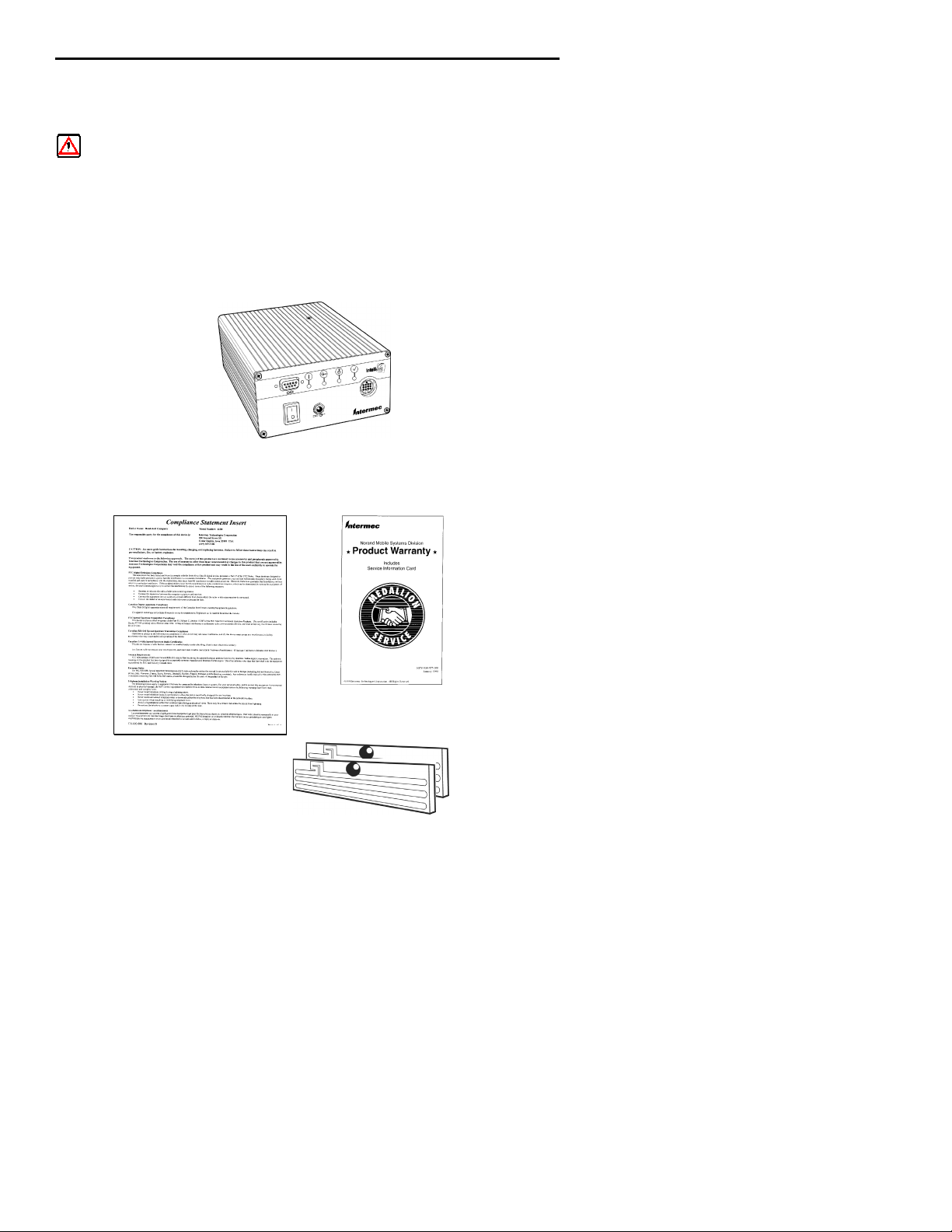
Packing List
WARNING: This is a Class A product. In a domestic
environment this product may cause radio
interference in which case the user may be
required to take adequate measures.
Check to ensure that you receive these items:
Intermec
Model Number: ITRF24501
(part number country dependent)
Compliance Statement
RF ID 2450 MHz Dipoles on FR4 Sample Tags
p/n ITTF2451001
RRRR
2450 Fixed Reader
Product Warranty Card
2
Page 3
ITRF24501 Reader Quick Start Guide
Host Communication
Host communication comes through the 9-pin female D-sub
connector. Both RS-232 and RS-422 standards are supported as
ordered from the factory or service center.
Tab le 1 -1
RS-232 Connections
Pin Number
2 Serial Data from the Fixed Reader to the host
3 Serial Data to the Fixed Reader from the host
5 Ground
7 CTS (Clear to Send) to the Fixed Reader from the
8 RTS (Request to Send) from the Fixed Reader to the
Pin Number
1 Serial Data Out + from the Fixed Reader to the host
4 Serial Data Out -- from the Fixed Reader to the host
5 Ground
6 Serial Data In + to the Fixed Reader from the host
9 Serial Data In -- to the Fixed Reader from the host
Definition
host
host
Tab le 1 -2
RS-422 Connections
Definition
The default baud rate is 115.2 kbps with 8 data bits, no parity
and 1 stop bit.
3
Page 4

ITRF24501 Reader Quick Start Guide
Power Requirements
Power comes in from 8 to 10 volts DC. The Fixed Reader uses
less than 2 amps. Intermec supplies 9 volts DC at 2.4 amps
from Intermec power supply, #351-066-001.
User I/O
A general purpose I/O (Input/Output) connector provides signal
lines in and out of the reader allowing monitoring and/or control of external devices or functions.
The connector for this i s a 13-pin female circular DIN. The
mating male connector you need f o r mating with this is a CUI
# SD-130, (one source is Digi-Key #CP-1013-ND).
Tab le 1 -3
I/O Pin-outs
Pin Number
1GPIOIN0
2GPIOIN1
3GPIOIN2
4GPIOIN3
5GPIOOUT0
6GPIOOUT1
7GPIOOUT2
8GPIOOUT3
9, 10, 11, 12, 13 GROUND though individual 10 ohm resistors
Definition
Outputs and inputs have 12 volt transient suppression devices
to ground at the connector. Output s ignals are driven by
2N3904 NPN transistors (low level) with a 100 kohm pull--up
to +5 volts through a silicon diode, giving about a 4.3 volt high
level. An output can be pulled high from an external source as
high as 40 volts. This will however tend to pull the other outputs higher (through two 100k resistors). The low level will be
about 0.1 volt up to about 30 mA. The output low voltage will
4
Page 5

ITRF24501 Reader Quick Start Guide
climb higher as the sink current increases. There is no protection on this. You need to ensure that their load won’t require
thereadertosinkmorethan50mA.
Input signals should be 0 to +1.5 volt for a low input and +3.5
to +5 volts for a high input. Each input has a 1.1 kohm resistor
in series with clamping diodes, but only about 1PA is used until
the input exceeds the 0 to +5 volt input range. There is also a
weak (100 kohm) pull--up to +5 volt on each input.
5
Page 6

ITRF24501 Reader Quick Start Guide
Connecting and Getting Started
WARNING: FCC regulations limit exposure to
radiofrequency (RF) radiation. To comply with
these regulations, operators of this device must
maintain a distance of at least 20 cm. (8 inches)
from the cover on the antenna assembly (The
cover on the antenna is the dome shaped
surface). While the device is on, the operator’s
body and parts of the body such as eyes, hands,
or head, must be 20 cm. (8 inches) or farther
from the cover of the antenna assembly.
FCC regulations also require that the antenna
assembly of this device be installed in
accordance with the installation procedures to
allow the operator to comply with the limit.
6
Page 7
ITRF24501 Reader Quick Start Guide
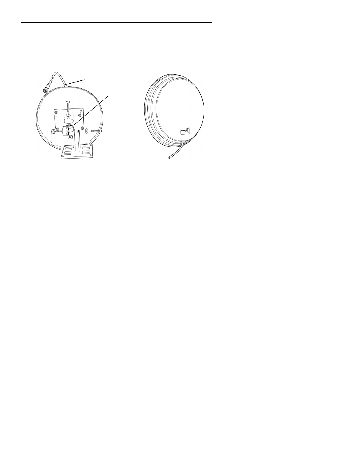
Antenna Installation
Ensure that you read the above warning before installing the
antennas and using your Reader product.
Reader to antenna cable
Mounting bracket
Back view Front view
1. Review the locations where the Reader products need integrated. Ensure that you have careful considered the
safe distances for product placement for workers and any
other personnel that may get in the RF path.
2. Place the radio and antennas with cabling are easily accessible f or installation and troubleshooting.
3. Use the mounting bracket to attach the antenna to a
fixed surface.
4. Attach the antenna to one of the four antenna ports on
the back of the Reader.
7
Page 8
ITRF24501 Reader Quick Start Guide
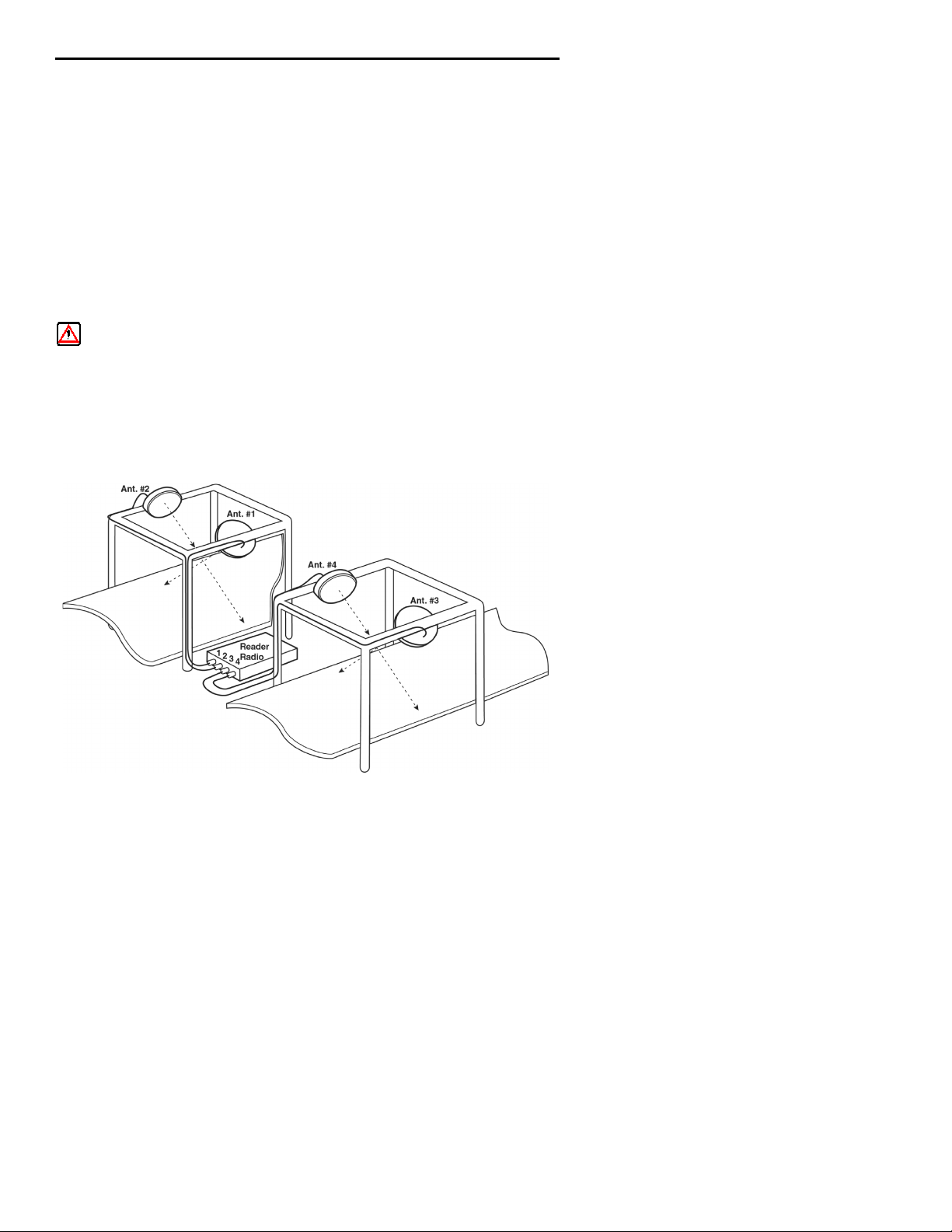
The following illustration is an example of a typical Reader
installation.
EXAMPLE: Two Product Line Conveyers, showing two antennas
on each line. Two antennas in a crossing pattern
provide angular diversity to improve read capability
when tag orientation is unknown.
The frames for these stations are PVC tubing with RF reflective Mylar liner X2. Ensure that an eight inch (20 cm) distance
from the antenna assembly is maintained to limit people’s exposure to radiofrequency (RF) radiation.
WARNING: While the device is on, the operator ’s body and
parts of the body such as eyes, hands, or head,
must be 20 cm. (8 inches) or farther from the
cover of the antenna assembly.
Conveyer Belt #1
Conveyer Belt #2
33” Max.
distance
to tag
A singular antenna in a portal may be sufficient
in applications where there is a known tag orientation
8
Page 9

ITRF24501 Reader Quick Start Guide
Connecting the Antenna to the Reader
1. Connect the antenna cable to a port.
2. Connect an SMA reverse--sex SMA terminator (Intermec
p/n 345-004-001) to any port that does not have an antenna attached.
"
NOTE:
Antenna ports
Each port must have either an antenna or a terminator connected.
4
3
2
1
SMA terminator
Back panel
Antenna cable
3. Connect the Reader to a power source using power supply
p/n 351-066-001 and country dependent AC power cord.
4. Turn on your reader.
Power supply
Power cord
9
Page 10
ITRF24501 Reader Quick Start Guide
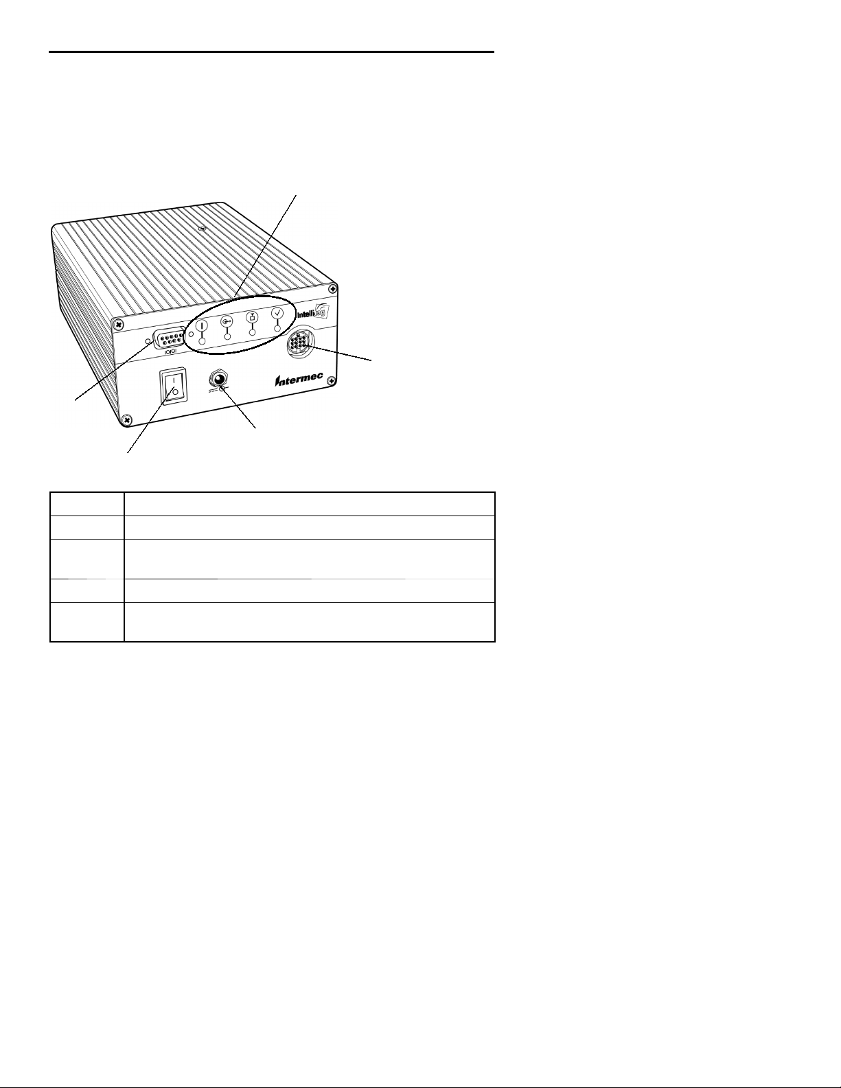
5. Review the front panel LEDs to become familiar with the
status indications you will receive from your Reader.
LEDs (left to right)
Auxiliary I/O connector
RS-232 or
RS-422 port
Power supply jack
I (ON) O (OFF) switch
LED Meaning
LED 0 Reader has power is initialized and ready.
LED 1 Reader is communicating with the host, it flashes
as data transfer occurs.
LED 2 Reader RF is ON and searching for TAGs.
LED 3 Reader is communicating with a TAG, it flashes as
transfer occurs.
10
Page 11

Troubleshooting
Troubleshooting
ITRF24501 Reader Quick Start Guide
Tab le 1 -4
Problem
Doesn’t recognize tag
Solution
1. Check to ensure antenna is connected to jack on Reader.
2. Ensure Reader is connected to
your computer.
3. Ensure computer is plugged into
ac outlet and computer is turned on.
4. Ensure tag is within range of antenna.
5. Access the Intermec web site
http://www.intermec.com or
http://NorBBS.Norand.com to d ownload and run the diagnostic test utility PENNRFID.EXE.
6. Call Intermec Technical Support
800--755--5505 (US or Canada)
425--356--1799 (elsewhere).
Diagnostic PENNRFID.EXE Utility
Should your Reader fail to read tags, download the test utility
from the Intermec web site (http://www.intermec.com). This
utility PENNRFID.EXE is a self-extracting zip file that
includes installation instructions and a test utility to check the
operation of the Reader on a laptop or desktop computer. Refer
to the README.TXT file included in the zip file for
instructions on using the test utility.
Should the reader fail after running this utility, contact Intermec Technical Support and give them the error codes you observe. They will step you through further diagnostic troubleshooting.
11
Page 12

ITRF24501 Reader Quick Start Guide
Performance Specifications
Dependent upon operating conditions and demands expected. If
used in a normal office environment with good read conditions,
you could expect to read up to 30 tags per s econd. Tags located
too f ar away or in poor locations, with respect to interfering
objects, provides poor results.
Tab le 1 -5
ITRF24501 Reader Specification
Criteria
Operating Temperature --20dto +55dC(--4dto +131dF)
Storage Temperature --40dto +85dC(--40dto +185dF)
Humidity 10-- 95% relative humidity, non-con-
Frequency 2400--2483 MHz
Tag data rates 32K bits per second
Operating Voltage 8--10 VDC
Ripple 200 mV maximum Peak to Peak
Modulation AM, On/Off key
Coding Manchester: From reader to tag
RF Output Impedance 50:w/better than 10 dB return
Bus Interface Serial RS-232, RS-422
Read Range Up to 33 inches (single tag, anten-
Write Range Typically 70% of Read Range
Tag identification Up to 30 tags per second
Write Rate 20 ms per byte per tag
Read current 1.6A
Standby (I) 600 mA
Protocol ANSI NCTIS T6 256--2001 stan-
Range
densing process
loss
na, and environment dependent)
dard
12
Page 13

ITRF24501 Reader Quick Start Guide
Table 1-5 (Continued)
ITRF24501 Reader Specification
Criteria Range
Vibration 1.0 GRMS. 10 to 500 Hz in three
axis
Channel switching 30 uS (TX on a channel, to TX on
any other channel)
Frequency stability --50 to +50 PPM
Transmitter power output 900 mW(typical) 1000 (max.) mW
@ connector. Assume 1 dB of antenna and cable loss across total
passband.
Safety Approvals USA: UL Listed, C22.2 No. 950/UL
1950 (605969)
Electrical Emissions USA: FCC Part 15, Class A
RF Approval USA: 2.4 GHz Frequency FCC
15.247
Europe: 2.4 GHz Frequency ETSI
300 400
Shock 20Gs, 11 ms, half sine pulse
ESD +8 KV (indirect) +4 KV (direct); 15
KV (except conductor pin (4KV)) in
direct air discharge
Mean Time Between Failures TBD hours
13
Page 14

ITRF24501 Reader Quick Start Guide
Corporate Headquarters
6001 36th Avenue West
Everett, Washington 98203
tel 425.348.2600
fax 425.355.9551
www.intermec.com
ITRF24501 Reader, Quick Star t Guide-March, 2002
*962054051*
962054051 REV A
14
 Loading...