

Page 1
Chapter 11 Maintenance
Printhead Cleaning, cont'd.
87
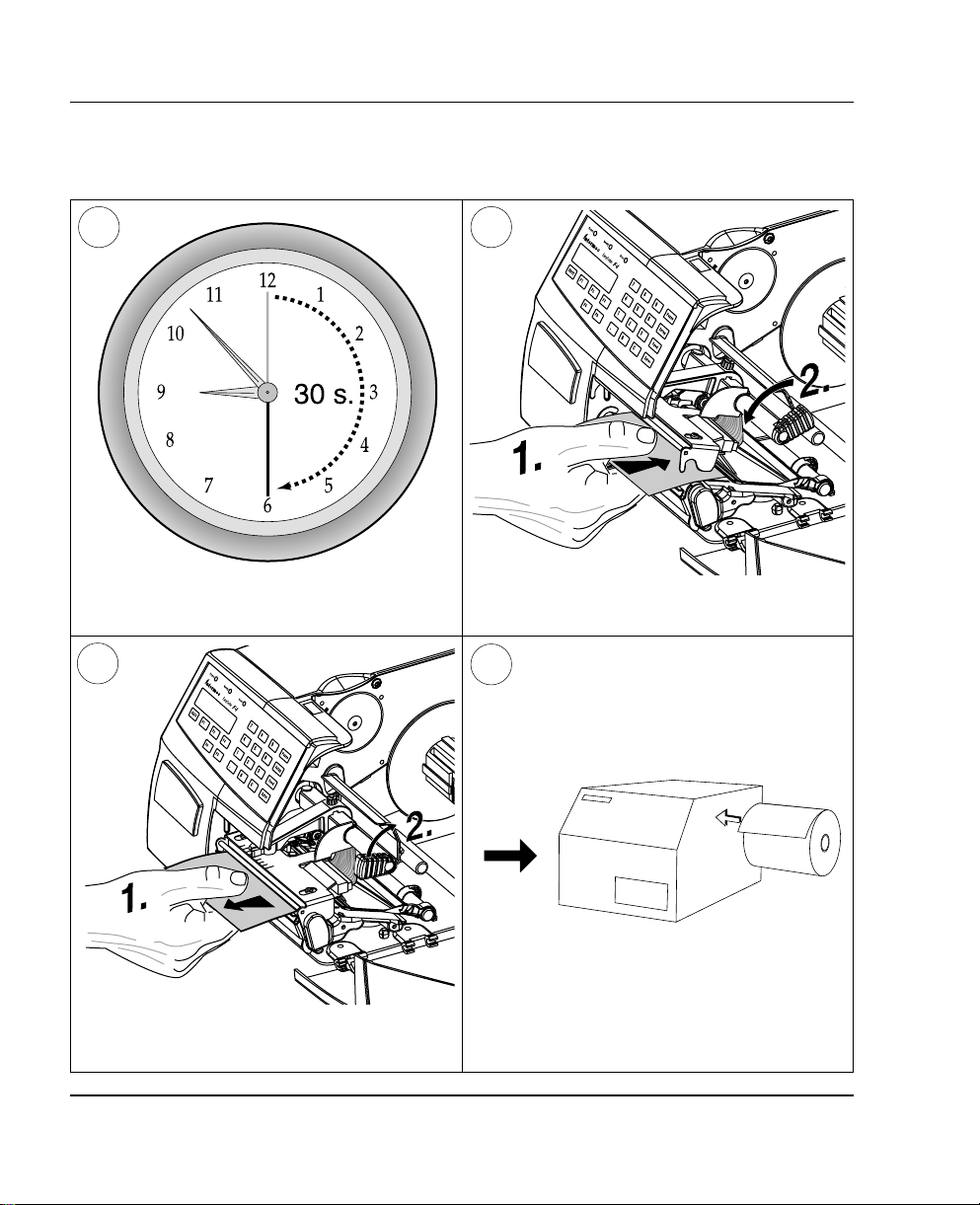
Wait for approx. 30 seconds to allow the
cleaning fl uid to dissolve the residue.
9
Pull out the cleaning card. If necessary, repeat
the process with a new cleaning card.
Insert most of the cleaning card under the
printhead (1). Close the printhead (2).
10
Allow the cleaned parts to dry before loading
any paper.
Intermec EasyCoder F4 – Installation & Operation Ed. 278
Page 2
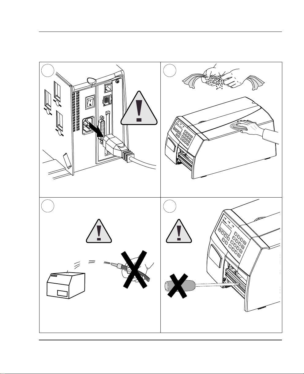
External Cleaning
Chapter 11 Maintenance
1
Always remove the power cord
before cleaning!
3
2
Wipe external surfaces with a soft cloth slightly
moistened with water or a mild detergent.
4
Never spray the printer. Protect it from water
when cleaning the premises.
Intermec EasyCoder F4 – Installation & Operation Ed. 2 79
Never use any sharp tools for removing stuck
labels. The printhead and rollers are delicate.
Page 3
Chapter 11 Maintenance
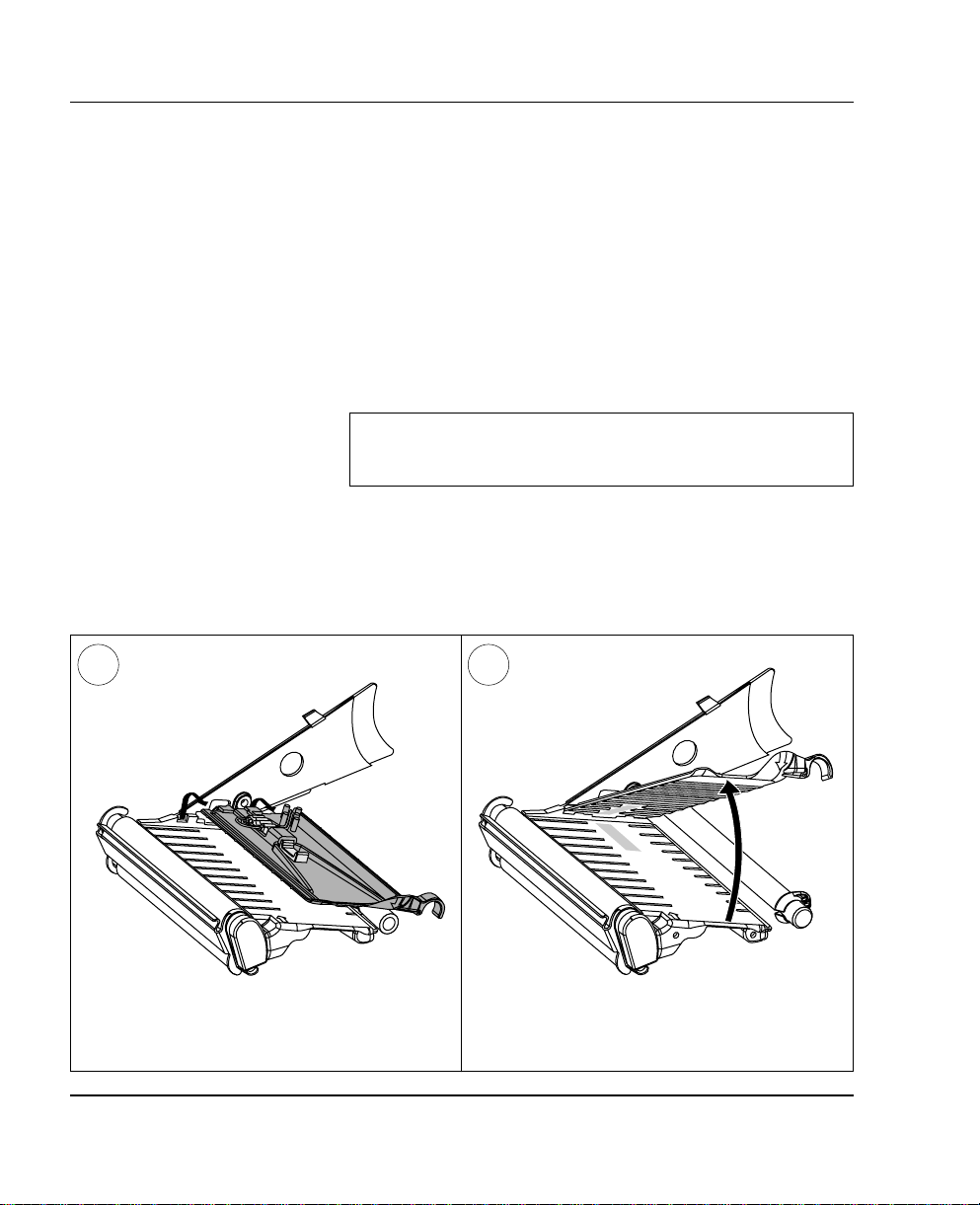
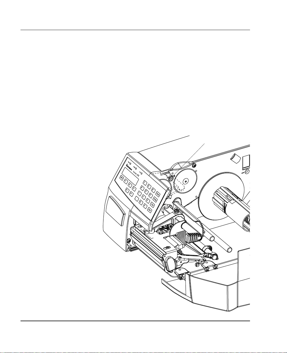
Cleaning the
Paper Guides
Both parts of the label stop sensor, which controls the paper feed, are
covered by plastic guides. The guides are provided with seemi ngly
non-t ranspa rent area s, thr ough which the l ight betwee n the two
part s of the lab el stop sensor is tra n sm itte d. T hese areas (indicated
by a shade of gre y in illustration #2 belo w) mus t be kep t c l ean from
dust, stuck labels, and adhesive residue.
If the printer starts to feeed our labels in an unexpected way. lift the
upper guide – as described be lo w – and c h eck f or an ythin g th at m a y
block the beam of light (dust, stuck labels, adhesive residue etc.).
If necessa ry, clean the guides using a cleaning card or a soft cloth
soaked with isopropyl alcohol. Do not use any other the of chemical.
Be careful not to scratch the guides.
Caution!
Isopropyl alco hol [(CH
fl ammable, moderately toxic and mildly irritating substance.
1 2
CHO H; CA S 67- 63- 0] is a h ighly
3)2
Lift the inner part of the upper guide and
pull it outwards,disengaging it from the lower
guide. Take care not to damage the cable.
Tilt the upper guide upwards and clean the
areas marked with grey. After cleaning, reas-
semble in reverse order.
Intermec EasyCoder F4 – Installation & Operation Ed. 280
Page 4
Chapter 11 Maintenance
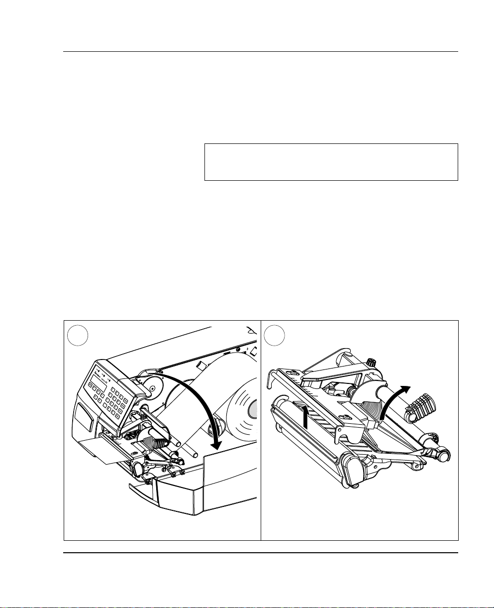
Printhead
Replacement
The printhead is subject to wear both from the direct thermal paper
and from the rapid heating and cooling process during printing. Thus,
the printhead will require periodical replacement.
Time between printhead replacements depends on the print images,
the type of paper in use, the amount of energy to the printhead,
and several other factors.
Note!
Whi le repla cing the pr inth ead, t he power sh ould b e switch ed
off.
1 2
Turn the printhead lift knob clockwise to lift
Open the side door.
Intermec EasyCoder F4 – Installation & Operation Ed. 2 81
the printhead.
Page 5
Chapter 11 Maintenance
Printhead Replacement, cont'd.
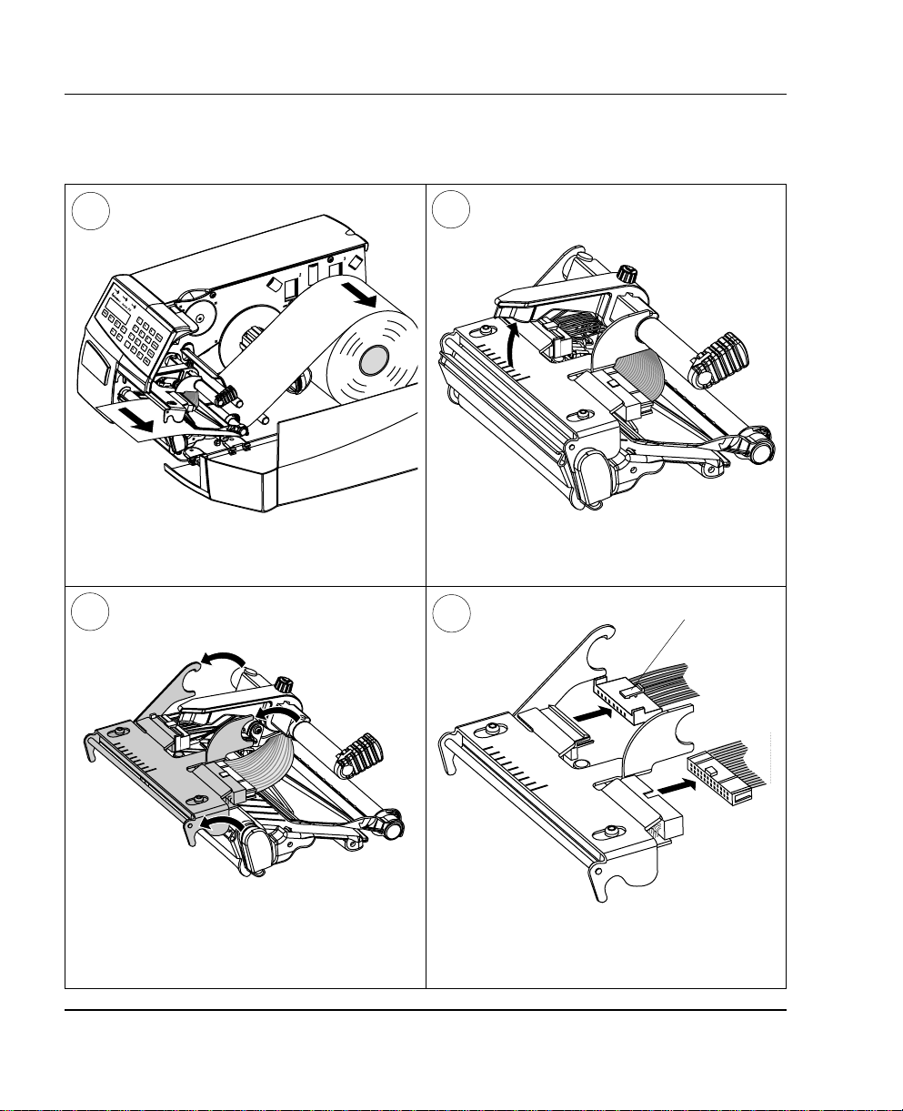
3
Remove the paper, if any.
5
4
Pull the printhead bracket away from the
magnet in the pressure arm.
6
Snap-lock
Disconnect the printhead bracket from the print
mechanism – as indicated by the arrows – and
pull out the printhead as far as the cables allow.
Disconnect the cables from the printhead. Note
the snap-lock on the inner connector. Pull at the
connectors – not the cables!
Intermec EasyCoder F4 – Installation & Operation Ed. 282
Page 6
Printhead Replacement, cont'd.
87
Chapter 11 Maintenance
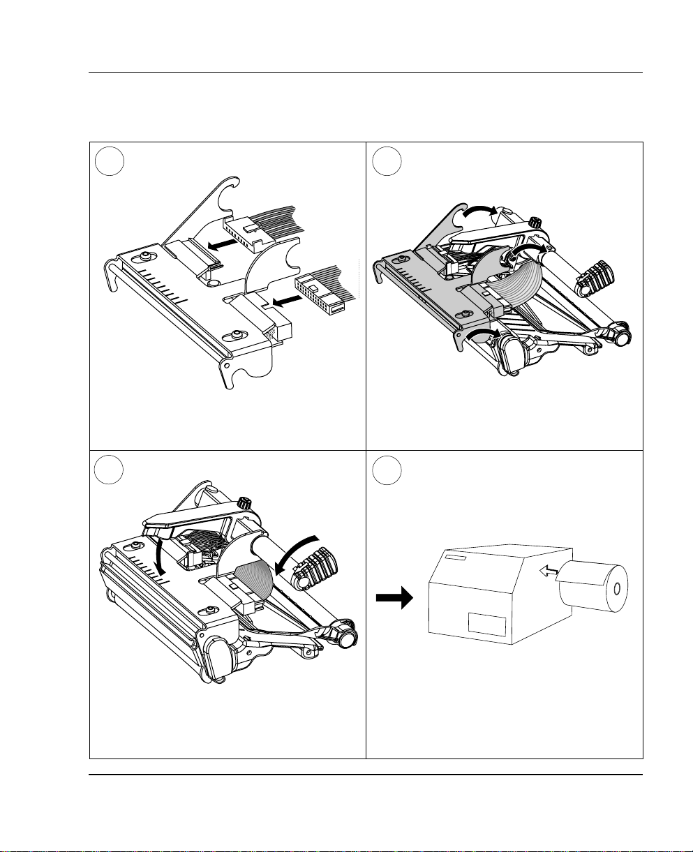
Connect the two cables to the replacement
printhead.
9
Close the printhead so the magnet engages the
printhead bracket.
Intermec EasyCoder F4 – Installation & Operation Ed. 2 83
Put back the printhead in reserse order and
check that the printhead cables run freely.
10
Load a new supply of paper as described ear-
lier in this manual.
Page 7
Chapter 12
Adjustments
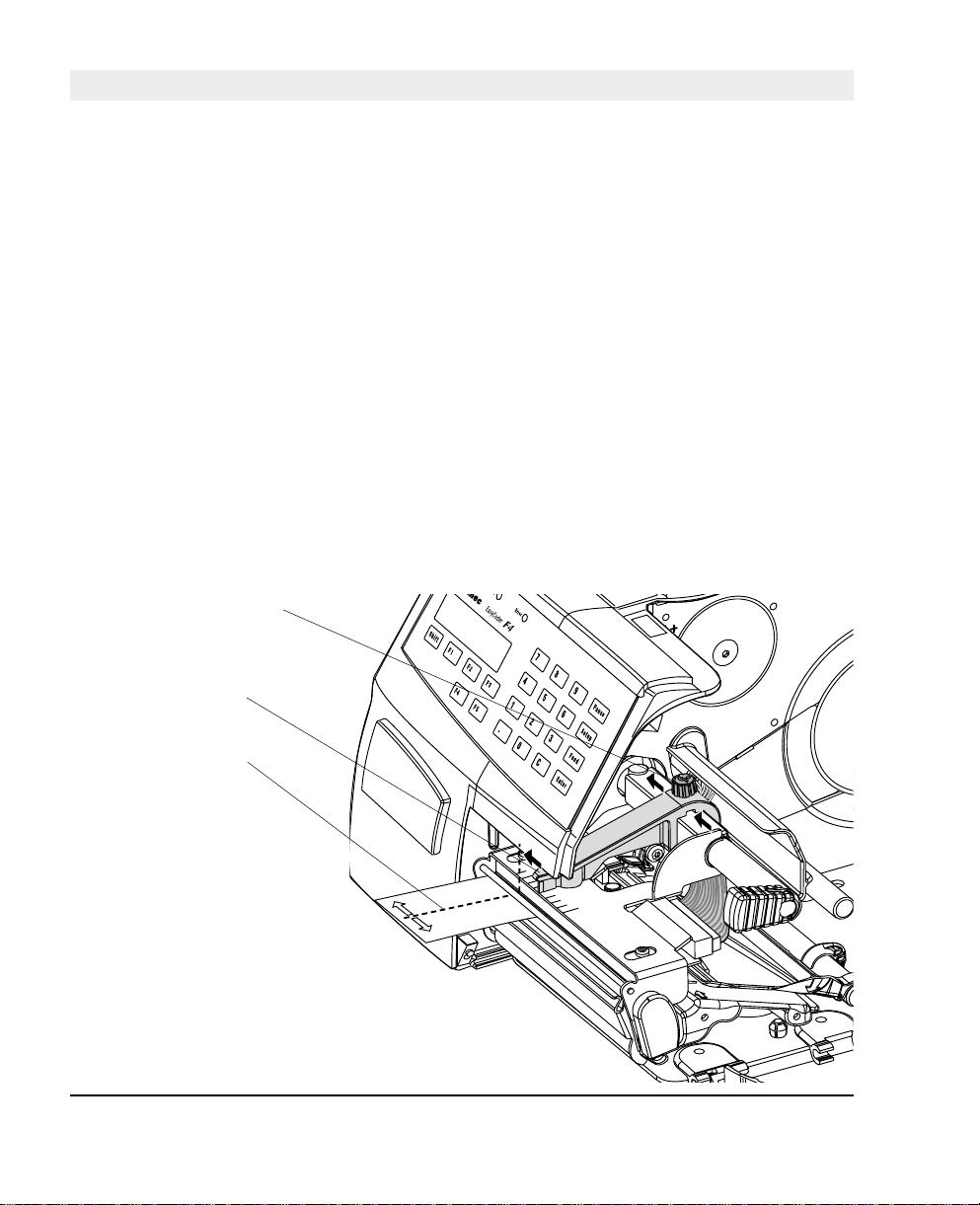
Narrow Labels
Adjustment
Nut
Pressure Arm
Centre of Paper
The printer is factory-adjusted for full size paper width. When using
paper less than full width, it is recommended to adjust the pressure
arm so it becomes cent red on t he pap er. Thereby, an even pressure
across the paper is obtained.
A poorly adjusted pressure arm may be detected by a weaker printout
on the inner pa rt of a less than f ull width paper. Similarly, when
reverting to a wider paper, the arm should be adjusted, or the printout
on the outer part of the paper could be weak.
T o ad just the pressure arm, proceed as follo ws:
• Loosen the nut that holds the pressure arm. Move the arm inwards
or outwards until the arrow on the tip of the arm becomes
centre-aligned with the paper web.
While moving the arm, push at the part where the nut is situated,
not at the tip. If the arm is hard to move, lift the printhead and pull
the printhead bracket free from the magnet in the arm.
• After having centred the arm, lock it by tightening the nut.
Intermec EasyCoder F4 – Installation & Operation Ed. 284
Page 8
Chapter 12 Adjustments
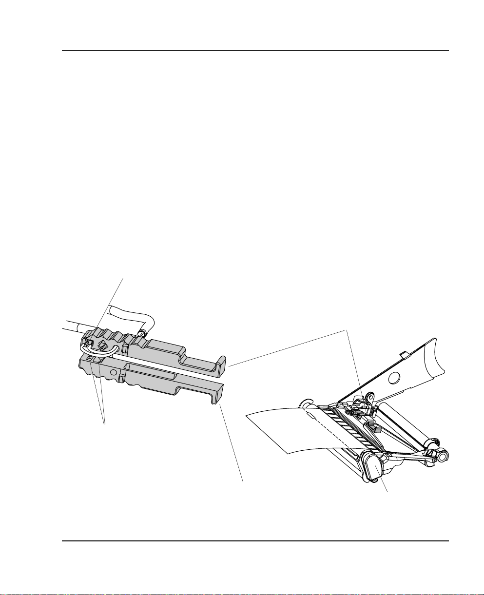
Label Stop Sensor
Position
One Sensor
The label stop/black mark sensor (LSS) is a photoelectric sensor that
controls the printer's paper feed by detect ing gaps between labels,
slots in paper strip, or black marks, depending on the printer's setup
in regard of media typ e (see chapter 6 “Setting Up the Pri nter”).
A prerequisite is obviously that the LSS is aligned with the slots
or black marks.
Thus, the LSS can b e moved laterally between 5 fi xed po sit ions.
There is one sensor on top of the upper paper guide and underneath
the bottom of the print unit. These two guides must be set individually
to th e same pos ition. Pu sh them inwa rds as fa r as they go a nd
then pull them out – one at the time – while counting the clicks
from the snap-locks.
The various dete ction points of the sensor in relation to the inner
edge of the paper are as follows:
One click out 3 mm .118"
Two c licks out 8 mm .3 1 5 "
Three clicks out 12 mm .47 2"
Four clicks out 16 mm .639"
Five c licks out 20 mm .787"
If usi ng irr egula rly shape d labels, a lign t he LSS with t he fron t
tips of the labels
Upper part of LSS
One Diode + One Sensor
Lower part of LSS
(printhead and headlift shaft omitted for
Intermec EasyCoder F4 – Installation & Operation Ed. 2 85
Print Unit
improved visibility)
Page 9
Chapter 12 Adjustments
Printhead
Pressure
The pressure of the thermal printhead against the paper is factory
adjusted. However, the use of thicker or thin ner pap er t ha n nor ma l
could require the printhead pressure to be readjusted.
Using a fl at-tipped screwdriver, turn the adjustment screw clockwise
for increased pressure (+), or counter-cl ockwise for less press ure (-).
Print a few labels, preferably test labels (see chapter 6 “Setting Up
the Printer”), and check the printout. Increa sed pressure general ly
gives a da rker pri ntout and v ice versa. Repe at until t he desir ed
result is obtained.
T o return to the factory setting, tighten the screw (+) as far as it goes
and then loosen it (-) six (6) full turns.
Note!
Do not use a higher prin thead pressure than necessary, because it
may increase the wear of the printhead and thus shorten its life.
Adjustment Screw
Intermec EasyCoder F4 – Installation & Operation Ed. 286
Page 10

Appendix 1
Technical Data
Printing
Print T echnique Direct Thermal
Printhead Resolution 8 dots/mm (203.2 dpi)
Print Speed (variable) 100 – 200 mm/sec. (≈ 4 – 8"/sec.)
Print Width (max) 104 mm (4.095") = 832 dots
Print Length (max) 32767 dots = 409.5 cm1
Media Width (min/max) 25 – 114.3 mm ( 1 –4.5") Standard paper guide
Media Width (min/max) 40 – 114.3 mm ( 1 .57 – 4.5") Quick-Load guides
Paper Roll Diameter (max) 213 mm (8.38") Short door/no rewind
Paper Roll Core Diameter 38 – 40 mm ( 1 .5") or 76 mm (3")
Print Directions 4
Modes of Operation
T ear Off Yes
Peel Off Optional Requires Rewind Unit
Firmware
Operating System Intermec Fingerprint 7.3 1 Incl. Direct Protocol
Smooth Fonts T rueDoc and T rue Type fonts
Built-in scalable fonts (std) 15 Unicode fonts
Built-in bar code symbologies (std) 36
Startup Program (std) Intermec Shell 4.4
Physical Measures
Dimensions (W x L x H) 244 x 397 x 178 mm (9.6 1 x 15 .63 x 7.00") w. Long side door
Weight (excluding media) ≈ 7 kgs ( 1 5.5 lbs) Depending on model
Ambient Operating Temperature +5°C – +40 ° C (+41 °F – +104° F)
Humidity 20 –80% non-condensin g
Electronics
Microprocessor 32 bit RISC
On-board Flash SIMMs 1 – 2 Std. 1 x 2 Mbytes
On-board DRAM SIMM 1 Std. 4 Mbytes
Real-Time Clock Option 10+ years life
Power Supply
Mains Voltage >90 – <264 V AC, 45 – 65 Hz
PFC Regulation IEC 61000-3-2
Maximum Power Consumption Continuous 1 40 W; Peek 300W
2
Intermec EasyCoder F4 – Installation & Operation Ed. 2 87
Page 11

Appendix 1 Technical Data
Technical Data, cont’d.
Sensors
Label Gap/Black Mark/Out of Paper Yes 5 fixed positions
Printhead Lifted Yes
Controls
Control Lamps 3
Display 2 x 16 character LCD w. background light
Keyboard 22 keys membrane switch type
Print Button 1
Beeper Yes
Data Interfaces
Serial 1 x RS 232C + 1 x USB
Bar Code Wand Yes
Electronic Keys 2 For setup
Connection for Optional Interface Boards
Memory Card Adapter 1
Accessories and Options Flash or SRAM cards
RFID Module Option
Rewind Unit Option For peel-off operation
Paper Supply Spool Option Replaces hanger
3” Adapter for Paper Supply Spool Option
Short Side Door Option
Long Side Door Option
Label Taken Sensor Option
Real-Time Clock Option 10+ years life
Quick-Load Guides Standard
RS 232C Cable Option
EasySet Bar Code Wand Option For quick setup
Parallel Interface Board Option IEEE 1284
Double Serial Interface Board Option
Industrial Interface Board Option
EasyLAN 100I Interface Board Option Ethernet
External Alphanumeric Keyboard Option
Flash Memory Cards Option
Electronic Keys Option
1. The max. print length is also restricted by the amount of free DRAM memory.
2. Latin, Greek, and Cyrillic fonts according to Unicode standard are included.
3. Depending on model, the printer may be delivered with either a long or a short side door.
1 Future option
3
3
Fitted in some models
= 64 Mbit (8 MB)
88 Intermec EasyCoder F4 – Installation & Operation Ed.2
Page 12

Media Specifi cations
Appendix 2
Direct Thermal
Labels
Interme c offers t wo quality grades of dire ct t hermal paper for the
EasyCoder range of printers:
• Premium Quality: Top-coated papers with high demands on
printout qual ity a nd resistance against moisture, plasticisers and
vegetable o ils. Examples. . .
- T op Board - Duratherm II,
- Premium - Duratherm II Tag
- Duratherm Ltg.
- Duratherm IR
• Economy Quality: Non top-coated papers with less resistance to
moisture, plasticisers and vegetable oils. In all other respects, it is
equal to Pr emium Quality . Examples...
- Economy
- Eco Board
Intermec EasyCoder F4 – Installation & Operation Ed. 2 89
Page 13

Appendix 2 Media Specifi cations
Paper Roll Size
Core
Diameters: 38 – 40 mm (1 .5 ") or 76 .2 mm (3")
Width: Must not protrude outside the web.
The web must be wound up on the core i n such a way that the
printer can pull the end of the web free.
Roll
Max. diameter (internal supply only):
- Position 1 152 mm (6.00")
- Position 2 213 mm (8.38")
- Position 3 203 mm (8.00")
Max. width: 1 14.3 mm (4.50")
Min. width (standard): 25 mm (1. 00")
Min. width (Quick -Load): 40 mm (1.5 7")
Max. web thickness: 17 5 µm (0.007")
The max imum recommended web thickness is 175µm. A thicker
web may be used, but print quality wi ll be reduce d. Web stiffness
is also impor tant and must be bala nced against web thickness to
maintain print q uali ty.
Pap er rol ls fitte d insi de the p rin ter sho uld be wo und wit h the
printable side facing outwards.
The paper supply must not be exposed to dust, sand, grit, etc. Any
hard particles, howe v er s mall, can damage the printhead.
Intermec EasyCoder F4 – Installation & Operation Ed. 290
Page 14

Paper
Appendix 2 Media Specifi cations
Non-Adhesive Strip
⇐ a ⇒ Web Width:
Maximum: 114.3 mm (4.50")
Minimum (standard): 25.0 mm (1 . 00")
Minimum (Quick-Load): 40.0 mm (1.5 7")
Media T ype Setup:
• Fix length strip
• Var length strip
Intermec EasyCoder F4 – Installation & Operation Ed. 2 91
Page 15

Appendix 2 Media Specifi cations
Paper, cont'd.
Self-Adhesive Strip
⇐ a ⇒ Web Width (including backing paper):
Maximum: 114.3 mm (4.50")
Minimum (standard): 25.0 mm (1 . 00")
Minimum (Quick-Load): 40.0 mm (1.5 7")
⇐ b ⇒ Backing Paper
The backi ng paper must not extend more than a tot al of 1.6 mm
(0.0 6") out side th e paper a nd shou ld prot rude e qual ly on bot h
sides.
⇐ c ⇒ Paper Width (e xc l uding backing paper):
Maximum: 112.74 mm (4.43")
Minimum: 23.8 mm (0.94")
Media T ype Setup:
• Fix length strip
• Var length strip
Intermec EasyCoder F4 – Installation & Operation Ed. 292
Page 16

Paper, cont'd.
Appendix 2 Media Specifi cations
Self-Adhesive Labels
⇐ a ⇒ Web Width (including backing paper):
Maximum: 114.3 mm (4.50")
Minimum (standard): 25.0 mm (1 . 00")
Minimum (Quick-Load): 40.0 mm (1.5 7")
⇐ b ⇒ Backing Paper
The backing pap er must not extend more than a tota l of 1.6 mm
(0.06") outside the paper and should protrude equally on bot h side.
Recommended min. transparency: 40% (DIN 53147).
⇐ c ⇒ Label Wid th (excluding backing paper):
Maximum: 112.7 mm (4.43")
Minimum: 23.8 mm (0.94")
⇐ d ⇒ Label Length:
Minimum: 8.0 mm (0.32")
Max label length: depends on DRAM size
Under favourable circumstances, a mini m um label length down to
4 mm (0 .16") could be used . It requires the s um of the label length
(d) and the label gap (e) to be lar ger than 7 mm (0.28"), that batch
printing is used , a nd th at no pull b ack of t he paper is per forme d.
Intermec does not guarantee that such short labels will work, but it
is up to the user to test this in his unique application.
⇐ e ⇒ Label Ga p:
Maximum: 21.3 mm (0.83")
Recommended: 3.0 mm (0.12")
Minimum: 1.2 mm (0.05")
The Lab el Stop Sensor must be able to det ect the extreme f ront
edges of the labels. It can be moved between 5 fi xed positions at the
following distances from the inner edge of the paper.
3 mm (.118")
8 mm (.3 1 5 ")
12 mm (.47 2")
16 mm (.63 9")
20 mm (.7 87")
Media T ype Setup:
• Label (w ga ps)
Intermec EasyCoder F4 – Installation & Operation Ed. 2 93
Page 17

Appendix 2 Media Specifi cations
Paper, cont'd.
Tickets with Gap
⇐ a ⇒ Web Width:
Maximum: 114.3 mm (4.50")
Minimum (standard): 25.0 mm (1 . 00")
Minimum (Quick-Load): 40.0 mm (1.5 7")
⇐ b ⇒ Cop y Length:
Min. length between slots: 8.0 mm (0.32")
Max. length between slots: depends on DRAM size
Under favoura ble circumsta nces, a minim um ticket le ngth down
to 4 mm ( 0.16") could b e used . It requires the s um of the c opy
length (b) a nd the d etec tion s lit heig ht (e) to be lar ger tha n 7
mm (0.28"), that batch printing is used, and that no pull back of
the pa per is per formed . Inter mec does n ot guaran tee that s uch
short l abels will work , but it is up to th e user to test this i n his
unique app l ic at io n.
⇐ c ⇒ LSS Detection Position:
Five fi xed positions (distance from inner edge of paper):
3 mm (.118")
8 mm (.3 1 5 ")
12 mm (.47 2")
16 mm (.63 9")
20 mm (.7 87")
⇐ d ⇒ Detection Slit Length:
The length of the detection slit (excluding corner radii) must be
mi nim um 2.5 m m (0.10" ) on eith er side of t he LSS d etec tion
positio n ( e).
⇐ e ⇒ Detection Slit Height:
Maximum: 21.3 mm (0.83")
Recommended: 1.6 mm (0.06")
Minimum: 1.2 mm (0.05")
Media T ype Setup:
• Ticket (w gaps)
Do not allow any per foratio n to break th e edge of the web, as this
may cause the web to split, resulting in a paper jam.
Intermec EasyCoder F4 – Installation & Operation Ed. 294
Page 18

Paper, cont'd.
Appendix 2 Media Specifi cations
Tickets with Black Mark
⇐ a ⇒ Web Width:
Maximum: 114.3 mm (4.50")
Minimum (standard): 25.0 mm (1 . 00")
Minimum (Quick-Load): 40.0 mm (1.5 7")
⇐ b ⇒ Cop y Length:
Minimum: 20.0 mm (0.8")
Maximum: depends on DRAM size
⇐ c ⇒ LSS Detection Position:
Five fi xed positions (distance from inner edge of paper):
3 mm (.118")
8 mm (.3 1 5 ")
12 mm (.47 2")
16 mm (.63 9")
20 mm (.7 87")
⇐ d ⇒ Black Mark Width:
The detectable width of the black mark should preferabl y be at least
5.0 mm (0.2") on either side of the LSS detection point.
⇐ e ⇒ Black Mark Length:
Maximum: 21.3 mm (0.83")
Common: 12.5 mm (0.5")
Minimum: 5.0 mm (0.2")
⇐ f ⇒ Black Mark Y-Position:
It is recom mended to place t he black mark as close to t he front
ed ge of th e ticke t as po ssible a nd us e a negat ive Sto p Adjust
valu e to cont rol the p aper fe ed, so t he ticke ts can b e prop erly
torn or cut off.
Media T ype Setup:
• Ticket (w mark)
Impor tant ! Preprint tha t may inter fere with the detec tion of the
black mark sh ould be avoid ed on th e bac k of the p aper. However,
th e LBL COND s tate men t allow s the se nsor to be tem porar ily
disabled during a specifi ed amount of paper feed in order to avoid
unintentional detection, see Intermec Fingerprint manuals.
The black mark should be non-refl ective carbon black on a whitish
backgr o und.
Do not allow any perforations to break the edge of the web, as this
may cause the web to split, resulting in a paper jam.
Intermec EasyCoder F4 – Installation & Operation Ed. 2 95
Page 19

Appendix 3
Interfaces
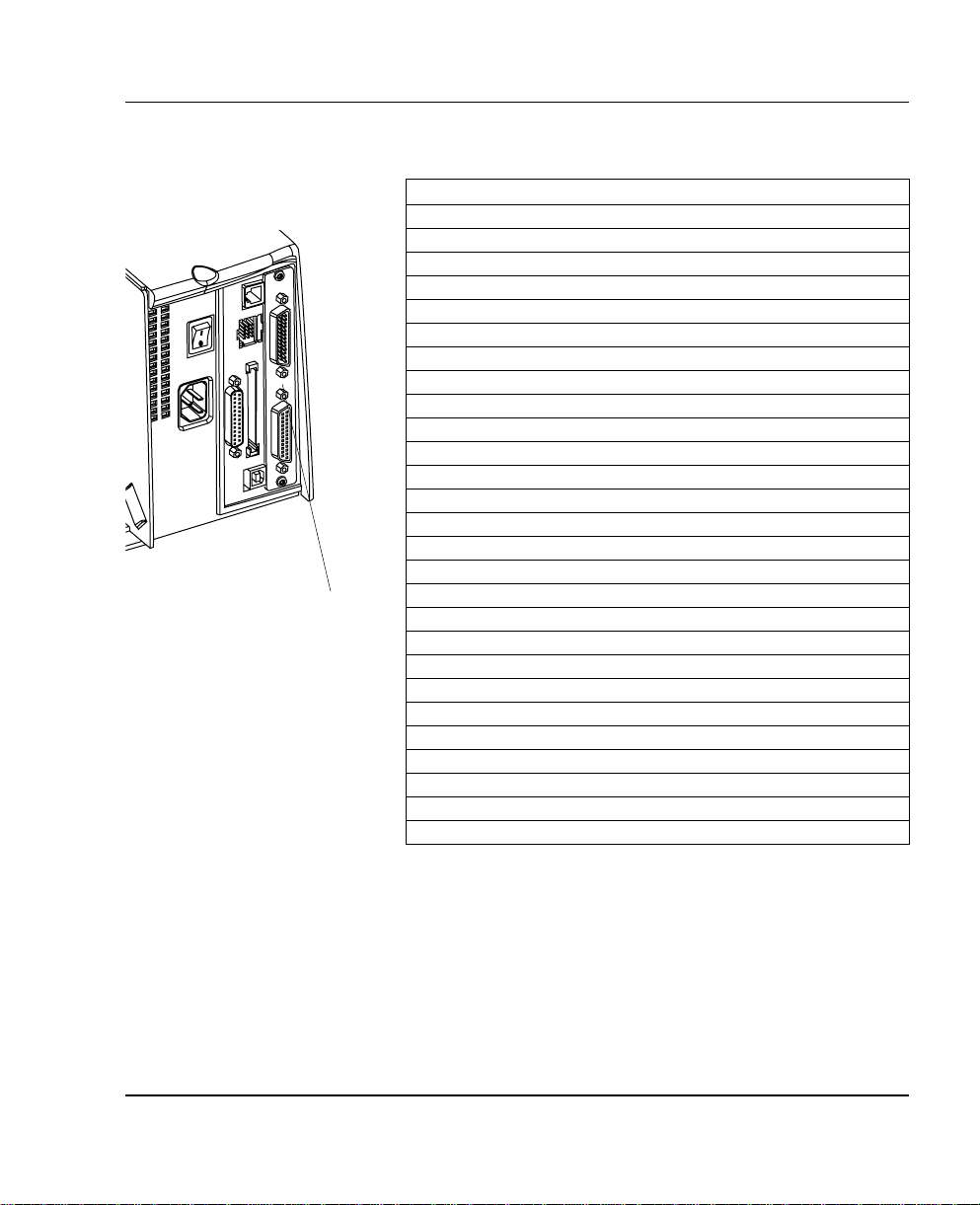
RS 232C Interface
The EasyCoder F4 has – as standard – two serial communication
interfaces: RS 232C on "uart1:" and US B (see next pag e).
Protocol
Defaul t se tup:
Baudrate: 9600
Char. length 8 bits
Parity: None
Stop bits: 1
RTS/CTS Disabled
ENQ/ACK: Disabled
XON/XOFF: Disabled (both ways)
New Line: CR/LF
To chang e the se ria l inte rfac e sett ings , see ch apter 6 “Setting
Up the Printer”.
Interface Cable
Computer end: DB-9 or DB- 25 female connector (PC)
Printer end: DB-25 male connector
Host EasyCoder F4 Host
Signal DB-9 DB-25 Signal DB-25 DB-25 Signal
1 1 1 1 shield
RXD 2 2 TXD 2 3 RXD
TXD 3 3 RXD 3 2 TXD
CTS 8 4 RTS 4 5 CTS
RTS 7 5 CTS 5 4 RTS
6 DSR 6 20 DTR
GND 5 7 Signal GND 7 7 GND
16 + 5V1 16
DSR 6 20 DTR 20 6 DSR
22 RI 22
"uart1:"
1
/. The external +5V is limited to 200 mA and is automatically turned
off at overload. It is intended to drive e.g. an external alphanumeric
keyboard connected to the RS 232C port.
Intermec EasyCoder F4 – Installation & Operation Ed. 296
Page 20

Appendix 3 Interfaces
USB Interface
USB = Uni ve r sal Serial Bus
The EasyCoder F4 has – as standard – one USB communication
port. To use the USB interface for printing from a PC, you need a
special USB printer driver installed in your PC.
Using an USB Class A - B cable , connect the Class A end to your PC
or hub and the Class B end to your EasyCoder F4 printer.
USB Class A connector.
Connect to PC or hub.
USB
Intermec EasyCoder F4 – Installation & Operation Ed. 2 97
Connect to USB receptacle on the printer's rear plate.
Note:
Th e USB in terf ace is pre sent ly not su ppor ted by t he Int erme c
Fingerprint fi rmware (v. 7.31 ).
USB Class B connector.
Page 21

Appendix 3 Interfaces
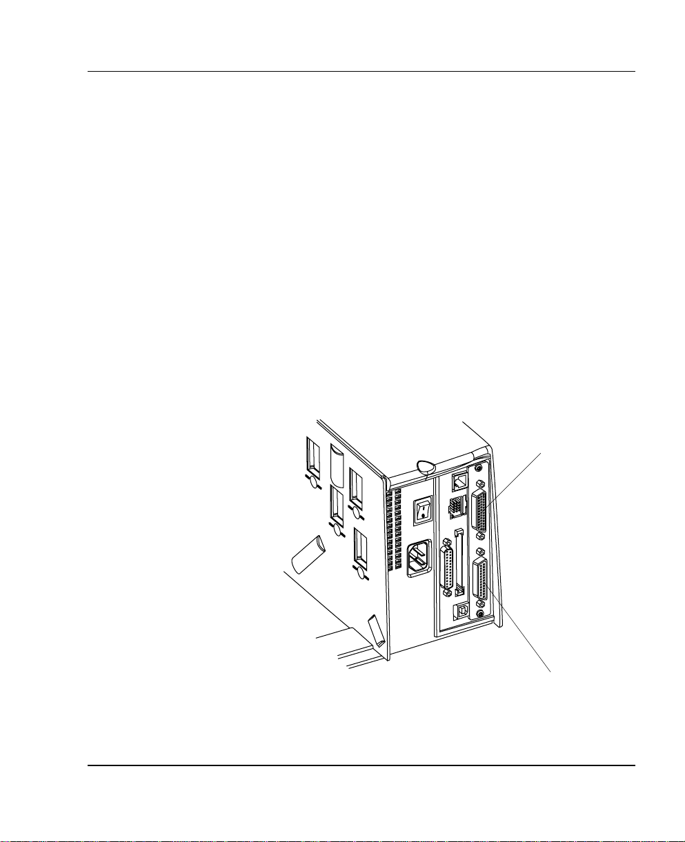
Double Serial
Interface Board
"uart2:"
1
/. Intermec Shell either automatically sets the correct std IN
and OUT port when an application is selected, e .g. a Windows
driver, or prompts you to select
one, see chapter 8.
The Easy Coder F4 can optional ly be fi tted with an extra double
seria l interface boa rd, which provides the pr inter with two more
serial por ts; "uart 2:" and "uart 3:". T hese ports can be con fi gured
for various types of serial communication in combination according
to the customer's request. Use the Intermec Fingerpr int inst r uction
SETSTDIO to select standard IN and OUT ports (by default "uart1:"
is both std IN and OUT port)
1
.
"uart2:" "uart3:"
RS 232C RS 232C
RS 422 Non-iso lated RS 422 Non- isolated
RS 422 Isolated 20 mA Current Loop
RS 485
"uart2:" Serial Port
The communication ports "uart2:" uses a female DB 25 connector.
Pin Signal Name Description
1 Not connected
2 TxD RS 232 T ransmitter
3 RxD RS 232 Receiver
4 RTS RS 232 Request To Send
5 CTS RS 232 Clear To Send
6 DSR RS 232 Data Set Ready
7 GND Ground
8–14 Not connected
1 5 +RS4 2 2 I +RS 4 22 R ec ei v e
16 +5V 5 Volt for external use (max. 200 mA)
1
1 7 -RS422I -RS 422 Receive
18 Not connected
19 +RS422O/+RS485 +RS 422 Transmit/+RS 485
20 DTR RS 232 Data Terminal Ready
21 -RS4 22O/-RS485 -RS 422 Transmit/-RS 485
22 RI R S 232 Ring Indicato r
23 Shield Optional shield for RS 422 and RS 485
24–25 Not connected
1
/. The external 5V is automatically turned off at overload.
Intermec EasyCoder F4 – Installation & Operation Ed. 298
Page 22
Appendix 3 Interfaces
Double Serial
Interface Board,
cont'd.
"uart3:"
"uart3:" Serial Port
The communication ports "uart3:" uses a male DB 25 connector.
Pin Signal Name Description
1 Not connected
2 TxD RS 232 Transmitter
3 RxD RS 232 Receiver
4 RTS RS 232 Request T o Send
5 CTS RS 232 Clear T o Send
6 DSR RS 232 Data Set Ready
7 GND Ground
8 Not connected
9 +20M1 +20 mA current loop
10 -20M1 -20 mA current loop
1 1 +TXD +TXD 20 mA current loop
12 - TXD - TXD 20 mA current loop
13 +20M2 +20 mA current loop
(prin te r act ive rece iv er )
14 -20M2 -20 mA current loop
(prin te r act ive rece iv er )
1 5 +RS4 2 2 I +RS 4 2 2 R e ce i v e
16 +5V 5 Volt for external use (max. 200 mA)
1 7 -RS422I -RS 422 Re ceive
18 +RxD +TXD 20 mA current loop
19 +RS422O/+RS485 +RS 422 Transmit/+RS 485
20 DTR RS 232 Data Terminal Ready
21 -RS4 22O/-RS485 -RS 422 T ran smit/-RS 485
22 RI RS 232 Ring Indica tor
23 Shield Optional shield for RS 422 and RS 485
24 Not connected
25 -RxD -TXD 20 mA current loop
1
/. The external 5V is automatically turned off at overload.
1
Intermec EasyCoder F4 – Installation & Operation Ed. 2 99
Page 23

Appendix 3 Interfaces
IEEE 1284
Parallel Interface
Board
"centronics:"
The EasyCoder F4 ca n optionally be fi t ted with an IEEE 1284-I
compatible parallel interface board1. The para llel por t is add ressed
in Intermec Fin g e rprint as d evice "centronics:". Select "centronics:"
as stand ard IN por t by means of the instr uction SETSTDIO (by
default, "uart1:" in std IN port)
Interface Cable Connectors
Computer end: Depends on type of host computer.
Printer end: 36 pin female IEEE 1284B Centron
Pin Signal Name
1 DStrobe
2–9 Data 0–7
10 Ack
11 Busy
12 PE
13 Select
14 AF
15 Not connected
16 Ground
17 Screen
18 +5V Ext
19–30 GND
31 Init
32 Error
33-35 Not connected
36 Selectin
2
.
1
/. Nibble, byte, E CP and EPP
from printer to host are presently
not supported.
2
/. Intermec Shell either automatically sets the correct std IN
and OUT p ort w hen an app lica tion is selected , e.g. a Windows
driver, or prompts you to select
one, see chapter 8.
Intermec EasyCoder F4 – Installation & Operation Ed. 2100
Page 24
Appendix 3 Interfaces
Industrial
Interface Board
The EasyCoder F4 can optionally be fitted with an Industrial
Int erfa ce Boar d, that p rovides t he pri nter w ith one ext ra ser ial
communicat ion port ("uar t2:"), which ca n be confi g ured for one
of the following alternatives
RS 232C
RS 422 Non-iso lated
RS 422 Isolated
RS 485
This port is identical to "uart2:" on the double serial interface
board.
The Industr ia l I nter face Boa rd a lso has a female DB- 4 4 con ne ctor
with...
8 digital IN ports with optocouplers
8 digital OUT ports with optocouplers
4 OUT ports with relays.
Refer to th e insta llation i nstr uctions for t he Indust rial I nterfa ce
Board for further information.
Industrial Interface
"uart2:"
Intermec EasyCoder F4 – Installation & Operation Ed. 2 101
Page 25

Appendix 3 Interfaces
EasyLAN 100i
Interface Board
The I nterme c EasyLAN 100 i Ether net inter face boa rd provides
the printer with a 10BaseT Ethernet or 100BaseTX Fast Ethernet
network c onnect ion. You c an commu nicate w ith the pr inter via
a LAN (L ocal Area Network) or provide the printer with its own
home page, so you can reach the printer via inter net on the world
wide web ( www ).
EasyLAN 100i supports most major computer systems and environments. You ca n assign passwords to restrict both login a nd pri nter
access. The inter nal EasyLAN 100i web pages allow you to continuously monitor printer status and to upgrade the fl ash memo ry of
the printer when new fi rmware becomes available.
EasyLAN 100i supports SNMP for remote monitoring.
When an EasyLAN 100i interface board is fi tted in the printer , s ome
extra menus will be added to the Setup Mode (see chapter 7 “Setup
Mode”). The Ethernet port is addressed in Intermec Fingerprint 7.3
or later as device "net1 :" (co mmunication channel 5).
RJ-45
connector
Intermec EasyCoder F4 – Installation & Operation Ed. 2102
Page 26
Appendix 4
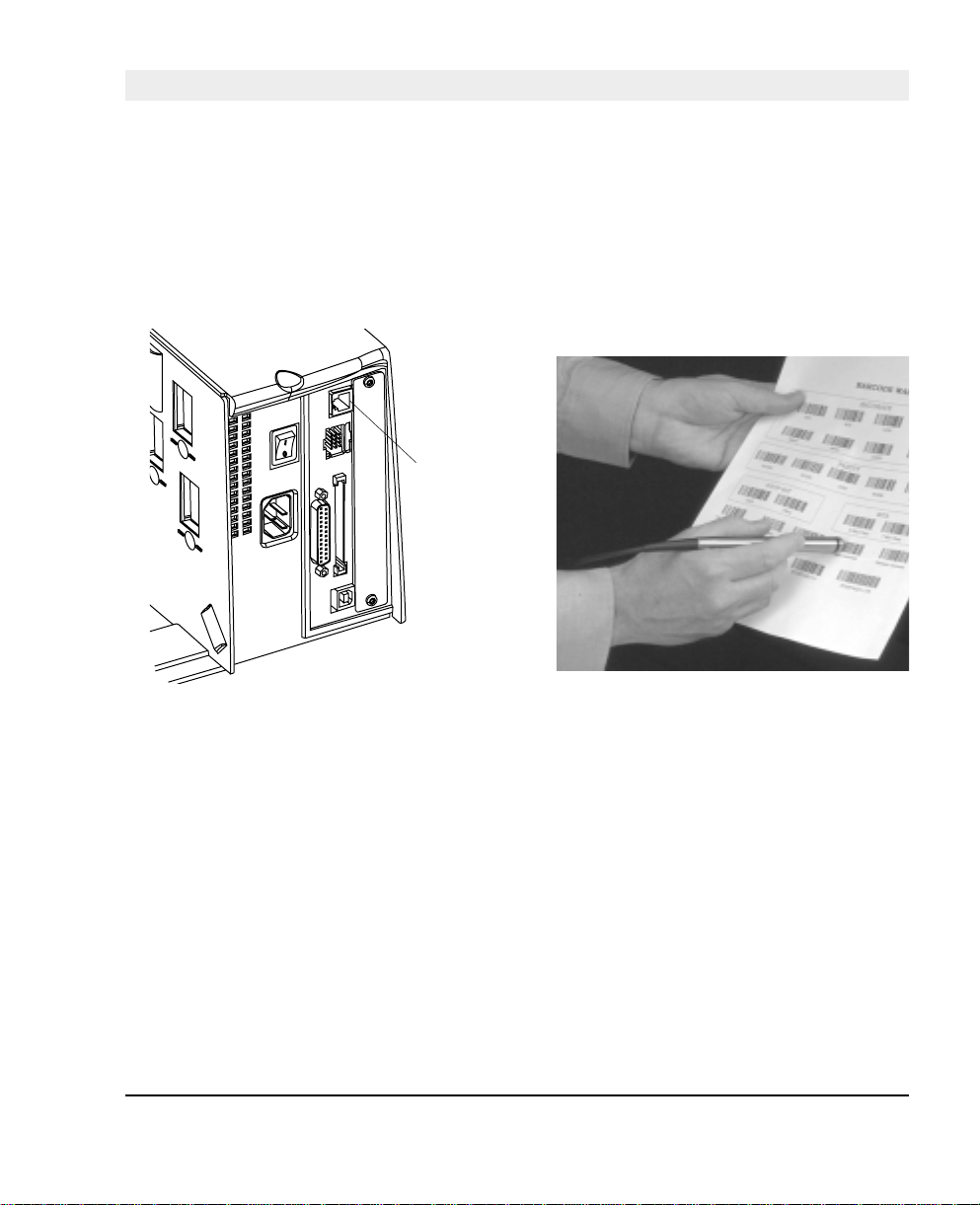
EasySet Bar Code Wand Setup
Connection and Operation
1. Connect the optional EasySet bar code wand to
the receptacle on the printer’s rear plate.
Connect
here!
3. When the bar code has been accepted, the printer
emits a short be ep and t he Ready control la mp
on the printer’s front blinks briefl y.
2. Read the appropriate bar code to set up the
printer. Hold the wand like a pencil and move it
rather swiftly across the bar code.
4. This manua l only conta ins a selection of setup
options. For information on how to produce your
own setup bar codes, please refer to the Intermec
Fingerprint 7 .31 Reference Manual.
Intermec EasyCoder F4 – Installation & Operation Ed. 2 103
Page 27

Appendix 4 EasySet Bar Code Wand Setup
Serial Communication on "uart1:"
Baudrate
Char. Length
Parity
Intermec EasyCoder F4 – Installation & Operation Ed. 2104
Page 28

Serial Communication on "uart1:", cont'd.
Appendix 4 EasySet Bar Code Wand Setup
No. of Stop Bits
RTS/CTS
ENQ/ACK
Reset comm. to default
XON/XOFF, Data to Host
Intermec EasyCoder F4 – Installation & Operation Ed. 2 105
Page 29

Appendix 4 EasySet Bar Code Wand Setup
Serial Communication on ”uart1:”, cont’d.
XON/XOFF, Data from Host
New Line
Start- and Stopadjust
Tear Off
Peel Off
Default
Intermec EasyCoder F4 – Installation & Operation Ed. 2106
Page 30

Contrast
Appendix 4 EasySet Bar Code Wand Setup
Intermec EasyCoder F4 – Installation & Operation Ed. 2 107
Page 31
Appendix 4 EasySet Bar Code Wand Setup
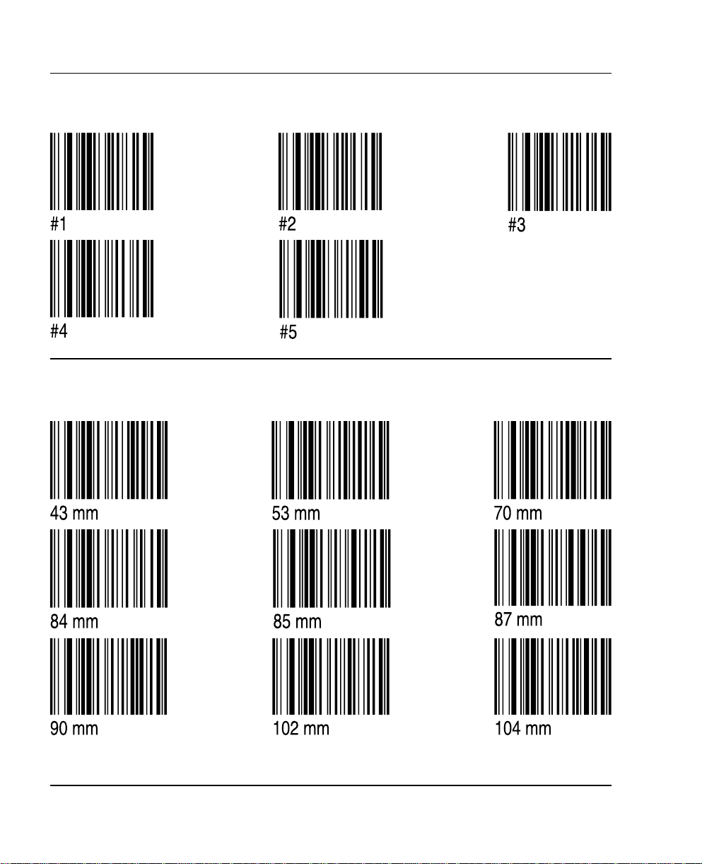
Test Labels
Media Width
Intermec EasyCoder F4 – Installation & Operation Ed. 2108
Page 32

Media Length
Appendix 4 EasySet Bar Code Wand Setup
Intermec EasyCoder F4 – Installation & Operation Ed. 2 109
Page 33
Appendix 4 EasySet Bar Code Wand Setup
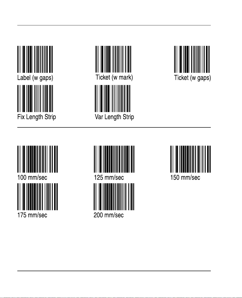
Media Type
Print Speed
Intermec EasyCoder F4 – Installation & Operation Ed. 2110
Page 34

Paper Type
Direct Thermal Printing (Europe)
Appendix 4 EasySet Bar Code Wand Setup
Direct Thermal Printing (USA)
Intermec EasyCoder F4 – Installation & Operation Ed. 2 111
Page 35

RFID Module
The EasyCoder F4 can optionally be fitted with an Intellitag® 500 RFID (radio
frequency identification) board that provides the printer with the means to preprogram Intellitag
printed.
The RFID board is addressed in Intermec Fingerprint 7.3 or later as device “uart2:”
The RFID board does not require connection to any device external to the printer.
The RFID module is fitted in the printer in the space allocated for optional interface
boards and therefore cannot be used in conjuction with, or in addition to, any of the
optional interface boards.
Refer to the installation instructions for the RFID Option Board for further
information.
Appendix 5 RFID Module
®
500 RFID SmartLabels when the bar code portion of the label is
112
Chassis location for RFID module
Intermec EasyCoder F4 – Installation & Operation Ed. 2
Page 36

Notes
113Intermec EasyCoder F4 – Installation & Operation Ed. 2
 Loading...