

Page 1

Compliance Statement Insert
Device Name: AC, DC Portable, Van, Wall Mount Printer Model Number: 6820
The responsible party for the compliance of this device is: Intermec Technologies Corporation
6001 36
Everett, WA 98203
USA
CAUTION: See users guide instructions for handling, charging, and replacing batteries. Failure to follow those instructions can result
in personal injury, fire, or battery explosion.
This product conforms to the following approvals. The user(s) of this product are cautioned to use accessories and peripherals
approved by Intermec Technologies Corporation. The use of accessories other than those recommended, or changes to this product that
are not approved by Intermec Technologies Corporation, may void the compliance of this product and may result in the loss of the users
authority to operate the equipment.
This device complies with Part 15 of the FCC Rules. Operation is subject to the following two conditions: (1) This device may not cause harmful
interference, and (2) this device must accept any interference received, including interference that may cause undesired operation.
FCC Digital Emissions Compliance
This equipment has been tested and found to comply with the limits for a Class B digital device, pur suant to Part 15 of the FCC Rules. These limits are
designed to provide reasonable protection against harmful interference in a residential installation. This equipment generates, uses and can radiate radio frequency
energy and, if not installed and used in accordance with the instructions, may cause harmful interference to radio communications. However, there is no guarantee
that interference will not occur in a particular installation. If this equipment does cause harmful interference to radio or television reception, which can be
determined by turning the equipment off and on, the user is encouraged to try to correct the interference by one or more of the following measur es:
• Reorient or relocate the radio of television receiving antenna.
• Increase the separation between the computer equipment and receiver.
• Connect the equipment into an outlet on a circuit different from that to which the radio or television receiver is connected.
• Consult the dealer or an experienced radio television technician for help.
Canadian Digital Apparatus Compliance
This Class B digital apparatus meets all requirements of the Canadian Interference-Causing Equipment Regulations.
Cet appareil numérique de la classe B respecte toutes les exigences du Règlement sur le matériel brouilleur du Canada.
Radio Wave Exposure Information for Model 6820 Configurations with Bluetooth Radio
The Model 6820 Printer has been designed to comply with applicable safety requirements for exposure to radio waves. These requirements are based on
scientific guidelines that include safety margins designed to assure the safety of all persons, regardless of age and health.
The Model 6820 Printer with the Bluetooth option has been evaluated using the FCC Maximum Permissible Exposure (MPE) exposure guidelines when used
with the Intermec accessories supplied or designated for this product. Use of other accessories may not ensure compliance with FCC RF exposure guidelines.
Users should maintain 20 cm (approximately 8 inches) of clearance between themselves and the 6820 Printer when using the Bluetooth radio interface.
th
Avenue West
578-100-026 Revision E Page 1 of 3
*578-100-026E*
*578-100-026E*
Page 2

DECLARATION OF CONFORMITY
(According to ISO/IEC Guide 22 and EN 45014)
THE PRODUCT HEREWITH COMPLIES WITH THE REQUIREMENTS OF :
THE LOW-VOLTAGE DIRECTIVE 73/23/EEC.
THE EMC DIRECTIVE 89/336/EEC.
THE R&TTE DIRECTIVE 1999/05/EC.
Manufacturer’s Name: European Representative:
Intermec Technologies Corporation Intermec International Incorporated
6001 36
Everett, WA 98203 Reading, Berkshire
USA RG1 8BT England
Declares that the product listed below:
Product Type: ITE/Residential, Commercial, and Light Industrial
Product Name: 6820 DC Portable, Van, Wall Mount Printers
Model Number: 6820 Product Options: ALL
Beginning Serial Number: All Date Issued: August 10, 2005
Conforms to the following product specifications:
Safety: IEC 60950-1 / EN 60950-1
EMC: EN 55022 : 1998 / CISPR Publication 22 : 1997, Class B Limits and Methods
EN 55024 : 1998 (CISPR 24) Information Technology Equipment – Immunity Characteristics –
Limits and Methods of Measurement
EN 61000-4-2 : 1995 – Electrostatic Discharge
EN 61000-4-3 : 1995 – Radiated RF Field
EN 61000-4-4 : 1995 – Electrical Fast Transients
EN 61000-4-5 : 1995 – Voltage Surge
EN 61000-4-6 : 1996 – Conducted RF Field
EN 61000-4-11 : 1994 – Voltage Dips, Short Interruptions, and Variations
EN61000-3-2 : 1995 + A1 : 1998 + A2 : 1998 + A14 : 2000 – Harmonic Current Emissions
EN61000-3-3 : 1995 – Voltage Fluctuation and Flicker
Radio: ETSI EN 300 328
I, the undersigned, hereby declare that the equipment specified above conforms to the above Directive(s) and
Standard(s).
Company Official: Michael Abel Position: Vice President
Signature:
European Contact: Luc Van Geel, Intermec International Incorporated, Sovereign House, Vastern Road, Reading,
Berkshire, RG1 8BT England; Phone INT+44 118 987 9400; Fax INT+44 118 987 9401
Czech Republic Contact: Global AmeriTech Corporation, Rytirska 10, 110 00, Prague 1, Czech Republic;
Phone INT+420-224 210 493; Fax INT+420-224 211 729
th
Avenue West Sovereign House, Vastern Road
Signed Copy on File Date: August 10, 2005
578-100-026 Revision E Page 2 of 3
*578-100-026E*
*578-100-026E*
Page 3

PROHLÁŠENÍ O DODRŽOVÁNÍ TECHNICKÝCH NAŘÍZENÍ
ZDE UVEDENÝ VÝROBEK SPLŇUJE POŽADAVKY:
SMĚRNICE 73/23/EEC PRO NÍZKONAPĚŤOVÁ ZAŘÍZENÍ
Jméno výrobce: Evropský zástupce:
Intermec Technologies Corporation Intermec International Incorporated
6001 36th Avenue West Sovereign House, Vastern Road
Everett, WA 98203, USA Reading, Berkshire
RG1 8BT England
prohlašuje, že níže uvedený výrobek:
Typ výrobku: Vybavení informační technologie/rezidenční, komerční a lehké průmyslové
Název výrobku: Model 6820 Kopírka
Číslo výrobku: Model 6820 Varianty: Všechny
Počáteční sériové číslo: Všechna Datum vydání: 10. Důstojný 2005
Splňuje následující parametry výrobku:
Bezpečnostní: IEC 60950-1 / EN 60950-1
EMC: EN 55022 : 1998 / CISPR vyhláška 22: 1997, Limity a metody třídy B
EN 55024: 1998 (CISPR 24) Vybavení informační technologie – charakteristiky odolnosti –
Limity a metody měření
EN 61000-4-2 : 1995 – Elektrostatický výboj
EN 61000-4-3 : 1995 – Vyzařované vysokofrekvenční pole
EN 61000-4-4: 1995 – Rychlé přechodové elektrické jevy
EN 61000-4-5: 1995 – Napěťový ráz
EN 61000-4-6: 1996 – Vedené vysokofrekvenční pole
EN 61000-4-8: 1995 – Magnetické pole
EN 61000-4-11: 1994 – Krátkodobé poklesy napětí, krátká přerušení a pomalé změny napětí
EN61000-3-2: 1995 + A1: 1998 + A1: 1998 + A1: 2000 – Vyzařované harmonické proudy
EN61000-3-3: 1994 – Kolísání napětí a blikání
Radio: ETSI EN 300 328
Já, níže podepsaný, tímto potvrzuji, že výše uvedené vybavení splňuje požadavky výše uvedených nařízení a
standardů.
Zástupce společnosti: Michael Abel Pozice: viceprezident
Podpis:
Evropský kontakt: Intermec International Incorporated, Sovereign House, Vastern Road, Reading, Berkshire, RG1 8BT England;
Telefon: MEZIN. +44 118 987 9400; Fax MEZIN.+44 118 987 9401
Kontakt v České republice: Global AmeriTech Corporation, Rytířská 10, 110 00, Praha 1, Česká republika;
Telefon: MEZIN. +420-224 210 493; Fax MEZIN. +420-224 211 729
Podepsaná kopie v evidenci Datum: 10. Důstojný 2005
(V souladu se směrnicí 22 ISO/IEC a EN 45014)
STRÁNKA JEDNA Z JEDNÉ STRÁNKY
SMĚRNICE EMC 89/336/EEC
SMĚRNICE R&TTE 1999/05/EC
578-100-026 Revision E Page 3 of 3
*578-100-026E*
*578-100-026E*
Page 4

User's Manual
6820 Series
80-Column Printer
Page 5

Intermec Technologies Corporation
Corporate Headquarters Technical Communications Department
6001 36th Ave. W. 550 Second Street SE
Everett, WA 98203 Cedar Rapids, IA 52401
U.S.A. U.S.A.
www.intermec.com
The information contained herein is proprietary and is provided solely for the purpose of allowing customers
to operate and service Intermec-manufactured equipment and is not to be released, reproduced, o r used for
any other purpose without written permission of Intermec.
Information and specifications contained in this document are subject to change without prior notice and do
not represent a commitment on the part of Intermec Technologies Corporation.
E 1997-2005 by Intermec Technologies Corporation. All rights reserved.
The word Intermec, the Intermec logo, Norand, ArciTech, CrossBar, Data Collection Browser, dcBrowser,
Duratherm, EasyADC, EasyCoder, EasyLAN, Enterprise Wireless LAN, EZBuilder, Fingerprint, i-gistics,
INCA (under license), InterDriver, Intermec Printer Network Manager, IRL, JANUS, LabelShop, Mobile
Framework, MobileLAN, Nor*Ware, Pen*Key, Precision Print, PrintSet, RoutePower, SmartSystems, TE
2000, Trakker Antares, and Virtual Wedge are either trademarks or registered trademarks of Intermec
Technologies Corporation.
Throughout this manual, trademarked names may be used. Rather than put a trademark (™ or ®) symbol in
every occurrence of a trademarked name, we state that we are using the names only in an editorial fashion,
and to the benefit of the trademark owner, with no intention of infringement.
There are U.S. and foreign patents pending.
Bluetooth is a trademark of Bluetooth SIG, Inc., U.S.A.
This product includes cryptographic software written by Eric Young (EAY@cryptsoft.com).
ii 6820 Series 80-Column Printer User’s Manual
Page 6

Document Change Record
This page records changes to this document. The document was originally released as Revision A.
Revision Date Description of Change
E 04/2004 Updated printer paper specifications in Chapter 1, “Introduction.”
F 08/2004 Merged technical reference information into user guide to create a user manual. Added
information about Bluetooth configuration, 600 Series Computers, 700 Series Computers, and the 6820 Configuration Utility application for Windows 2000 and Windows XP
operating systems.
G 12/2004 Updated information for the Bluetooth shutdown timer. Added Appendix C, “Printer
Fonts Test Print Jobs” to provide sample test font print jobs.
H 05/2005 Includes Bluetooth information for the wall mount printer.
J 10/2005 Included CK60 Handheld Computer infomration.
iii6820 Series 80-Column Printer User’s Manual
Page 7

iv
6820 Series 80-Column Printer User’s Manual
Page 8

Contents
Before You Begin xiii.............................................................
Safety Summary xiii.......................................................
Safety Icons xiv...........................................................
Global Services and Support xv..............................................
WhoShouldReadthisManual? xvi...........................................
Related Documents xvi.....................................................
Contents
Donotrepairoradjustalone xiii.......................................
First aid xiii.......................................................
Resuscitation xiii...................................................
Energized equipment xiii.............................................
Warranty Information xv............................................
Web Support xv...................................................
Telephone Support xv...............................................
1
Introduction
About the Printers 2.............................................................
Battery Options 3.........................................................
Internal Battery 3..................................................
Vehicle Battery 3...................................................
Connectors 4............................................................
Fixed Mount Printer 4..............................................
Portable Printer 4..................................................
Wall Mount Printer 4...............................................
Control Panel 5..........................................................
Hinges on Printer Cover 6..................................................
Internal Power Module 6...................................................
Paper 7.................................................................
Material Breakdown 7...............................................
Caliber Breakdown 8................................................
Printer Dimensions 9......................................................
Wall Mount Printers 9..............................................
Fixed Mount Printers 9..............................................
Portable Printers 9..................................................
Remote Connections 9.....................................................
Reset Button 10..........................................................
Fixed Mount or Portable Printer 10....................................
Wall Mount Printer 10..............................................
1...............................................................
2
Specifications 11................................................................
Inside Sales 12..................................................................
Operation
Check List 14..................................................................
13.................................................................
v6820 Series 80-Column Printer User’s Manual
Page 9

Contents
Installing Internal Battery 15.......................................................
Installing the Ribbon Cartridge 16..................................................
Adjusting the Print Head Gap 17...................................................
Loading Paper Tray 18...........................................................
FixedMountandPortablePrinters 18.........................................
Wall Mount Printer 19....................................................
Loading the Flat Paper Tray 19........................................
Loading the Compact Paper Tray 19....................................
Loading Paper into Printer 20......................................................
Positioning the Paper 20...................................................
Adjusting the Pinfeed Holders 21.............................................
Setting the Paper 22.......................................................
Inserting Computer in Terminal Holder 23...........................................
Inserting a 4000 Series or a 62XX Computer 23.................................
Inserting a 61XX, a 600 Series, a 700 Series, or a CK60 Computer 24................
3
Maintenance
Operating Guidelines 26..........................................................
General Cleaning 27.............................................................
Cleaning the Outside 27..........................................................
Cleaning the Inside 28...........................................................
Removing Old Ribbon Cartridge 29..........................................
Cleaning the Mask Spring 30................................................
Changing the Printer Settings 32...................................................
Protocol Selection Mode 32.................................................
Configuration Mode 32....................................................
Setting the Autofeed 32..............................................
Selecting the Bit Rate 33.............................................
Adjusting the Zero Print Option 33....................................
Using the 6820 Printer Configuration Utility
25..............................................................
35............................
4
Font Modules 36................................................................
Connecting to the Printer 37.......................................................
vi 6820 Series 80-Column Printer User’s Manual
Page 10

Contents
Instructions for Windows 95 or Windows 98 38........................................
Installation 38...........................................................
Configuration File Support 38...............................................
Configuration Utility Operation 38...........................................
Starting the Program 39.............................................
Main Menu 39....................................................
Load Printer Configuration 40........................................
Modify Printer Configuration 43......................................
Save Printer Configuration 47.........................................
Save Defaults to Printer 50...........................................
Alpha Keyboard 52.................................................
Instructions for Windows 2000 or Windows XP 53.....................................
Installation 53...........................................................
Configuration Utility Operation 56...........................................
Starting the Program 56.............................................
Default Printer Settings 61...........................................
Error Messages 61..................................................
About the Configuration Utility 62.....................................
Bluetooth Adapter 62...............................................
5
Control Code Definitions
Control Code Definitions 64......................................................
Buffers 64...............................................................
I/O Buffer 64.....................................................
Print (image) Buffer 64..............................................
Special Notations 64......................................................
General Printer Control Functions 64.........................................
Backspace 64......................................................
Beeper 65........................................................
Cancel Line 65....................................................
Carriage Return 65.................................................
Delete 65.........................................................
Form Feed 65.....................................................
Select Half-Speed Printing 66.........................................
Cancel Half-Speed Printing 66........................................
Set Inactivity Time for Sleep Mode 66..................................
Line Feed 66......................................................
Perform Master Reset 67.............................................
Set Print Position (absolute) 67........................................
Set Print Position (relative) 68.........................................
Select Top-Down Printing 68.........................................
Select Bottom-Up Printing 68.........................................
Select Unidirectional Printing 68......................................
Cancel Unidirectional Printing 68......................................
Select Unidirectional (one line) Printing 69...............................
63.................................................
vii6820 Series80-Column Printer User’s Manual
Page 11

Contents
Page Formatting Functions 69...............................................
Page Length 69....................................................
Line Spacing 70....................................................
Set Margins 71....................................................
Set Skip Over Perforation 72..........................................
Cancel Skip Over Perforation 72.......................................
Character Style and Text Mode Functions 72...................................
Select Condensed Mode (compressed) 72................................
Cancel Condensed Mode (compressed) 73...............................
Select Double-Strike Mode 73.........................................
Cancel Double-Strike Mode 73........................................
Select Double-Wide (expanded) Mode (one-line-only) 73....................
Cancel Double-Wide (expanded) Print (one-line-only) 74...................
Select Double-Wide (expanded) Mode 74................................
Cancel Double-Wide (expanded) Mode 74...............................
Select Elite Pitch 74................................................
Select Emphasized Mode 74..........................................
Cancel Emphasized Mode 75.........................................
Define Intercharacter Space 75........................................
Select Italic Mode 75................................................
Cancel Italic Mode 75...............................................
Master Select 75...................................................
Select Pica Pitch 76.................................................
Select Superscript Mode 77...........................................
Select Subscript Mode 77............................................
Cancel Subscript/Superscript Mode 77..................................
Select Underline Mode 77............................................
Cancel Underline Mode 77...........................................
Tabs and Tab Setting Functions 78...........................................
Horizontal Tabs 78.................................................
Vertical Tabs 79...................................................
Character Sets and User-Defined Functions 81..................................
Single Byte Character Sets 81.........................................
Double-Byte Character Sets 81........................................
Multi-Byte Character Sets 82.........................................
User Defined Characters 84..........................................
Graphics Functions 89.....................................................
Eight-Pin Graphics Modes 89.........................................
Nine-Pin Graphics Modes 91.........................................
Page Layout for Fanfold Paper 93...................................................
Printable Area 93.........................................................
Paper End Detection 94....................................................
Bluetooth Adapter
6
About the Bluetooth Adapter 96....................................................
Bluetooth Adapter Indicators 97.............................................
700 Series or CK60 Handheld Computer to 6820 Pass Through 97............
700 Series or CK60 Handheld Computer to Bluetooth Module Communication
Interface 97................................................
viii 6820 Series 80-Column Printer User’s Manual
95........................................................
Page 12

Contents
Bluetooth Adapter Power Management Flow 98.................................
Radio Power On/Off Mechanism 98..........................................
Security 99..............................................................
Persistent Storage 99......................................................
System Behavior/Software Considerations 99....................................
Remote Configuration 100.................................................
Bluetooth Performance 100.................................................
Diagnostics Capabilities 101.......................................................
RadioSelfTest 101.......................................................
Applications 102................................................................
System Qualification 103.........................................................
Operation Resilience 103...................................................
Environmental Specifications 103............................................
Temperature 103...................................................
Altitude 103......................................................
Vibration 103.....................................................
Unpackaged Drop 103..............................................
Terminal Inspection 103.............................................
Safety/Regulatory/Agency Requirements 104....................................
7
Default Configuration 105........................................................
Troubleshooting and Diagnostics
Checking the Power Source 108....................................................
Self-Test Failure 108.............................................................
Printer Mechanism Alignment 109..................................................
Communications or Host Computer 110.............................................
Communications Pin-Out Configurations 111.........................................
Troubleshooting 117.............................................................
Verifying the Printer Components 117........................................
Power Source Verification 117........................................
Printer Verification 117..............................................
Communications / Host Computer Verification 118.......................
Error Handling 118.......................................................
Run-Time Errors 118...............................................
Power-On Self-Test (POST) 119......................................
POST Errors 119..................................................
Fatal Errors 120...................................................
107......................................
ix6820 Series 80-Column Printer User’s Manual
Page 13

Contents
Self-Test Function Descriptions 121..........................................
Boot Block Program Verification 121...................................
Control Program Verification 121......................................
Font Module Verification 121.........................................
A2D Ch eck 121...................................................
Nonvolatile Diagnostic Memory Verification 121..........................
Nonvolatile Diagnostic Memory Update 121.............................
Detailed Printer Self-Test 122...............................................
Initiating Self-Test 122..............................................
Terminating Self-Test 122...........................................
Self-Test Report 122................................................
First Page of Self-Test 123............................................
Sample First Page of Self-Test 124.....................................
Second Page of Self-Test 125..........................................
Self-Test Failure 125................................................
Miscellaneous Troubleshooting Tips 126.......................................
Compatibility Issues 128...................................................
Diagnostic Information 128.......................................................
Nonvolatile Flash Storage 128...............................................
Updating Diagnostic Information 128.........................................
Accessing Diagnostic Information 129.........................................
A
Bluetooth Configuration Commands
Notation 134..................................................................
Command 134.................................................................
Operating Modes 135.....................................................
Command and Control Modes 136...........................................
Query Mode Commands 136.........................................
Set Local Bluetooth Device Name 137..................................
Set Class of Device/Service Field 137...................................
Set Service Name 137...............................................
Connectable On/Off: “ON” or “OFF” 137..............................
Specify Pag e Scan Timing 138........................................
Enable Discoverable 138.............................................
Specify Inquiry Scan Timing 138......................................
Set Encryption/Authentication: “PIN CODE” 138........................
Manage Security Modes 139................................................
Read Module Version 139............................................
Read Local Device Address 140........................................
Set Shutdown Timing 140...........................................
Clear Link Key Table 140............................................
Web Links 140.................................................................
133...................................
Cross-Reference Tables
B
Control Codes and Escape Sequences 142.............................................
x 6820 Series 80 -Column Printer User’s Manual
141..................................................
Page 14

Contents
Single Character Control Code Definitions 149........................................
Escape Sequence Quick Reference 150...............................................
Factory-Installed Printer Defaults 152................................................
C
I
PrinterFontTestJobs
Big 5 Traditional Chinese Character Set 156..........................................
Simplified Chinese Character Set 156................................................
IBM 437 Codepage Character Set 156...............................................
Japanese (Shift JIS) Character Set 157................................................
Korean Character Set 157.........................................................
International Character Set 157....................................................
Index
Control Codes 160..............................................................
General Index 163...............................................................
155...................................................
Files Index 169.................................................................
xi6820 Series 80-Column Printer User’s Manual
Page 15

Contents
xii 6820 Series 80-Column Printer User’s Manual
Page 16

Before You Begin
Safety Summary
Before You Begin
This section provides you with safety information, technical support
information, and sources for additional product information.
Your safety is extremely important. Read and follow all warnings and
cautions in this document before handling and operating Intermec
equipment. You can be seriously injured, and equipment and data can be
damaged if you do not follow the safety warnings and cautions.
Donotrepairoradjustalone
Do not repair or adjust energized equipment alone under any
circumstances. Someone capable of providing first aid must always be
present for your safety.
First aid
Always obtain first aid or medical attention immediately after an injury.
Never neglect an injury, no matter how slight it seems.
Resuscitation
Begin resuscitation immediately if someone is injured and stops breathing.
Any delay could result in death. To work on or near high voltage, you
should be familiar with approved industrial first aid methods.
Energized equipment
Never work on energized equipment unless authorized by a responsible
authority. Energized electrical equipment is dangerous. Electrical shock
from energized equipment can cause death. If you must perform
authorized emergency work on energized equipment, be sure that you
comply strictly with approved safety regulations.
xiii6820 Series 80-Column Printer User’s Manual
Page 17

Before You Begin
Safety Icons
This section explains how to identify and understand dangers, warnings,
cautions, and notes that are in this manual. You may also see icons that tell
you when to follow ESD procedures and when to take special precautions
for handling optical parts.
A warning alerts you of an operating procedure, practice, condition,
or statement that must be str ictly observed to avoid death or serious
injury to the persons working on the equipment.
Avertissement: Un avertissement vous avertit d’une procédure d e
fonctionnement, d’une méthode, d’un état ou d’un rapport qui doit
être strictement respecté pour éviterl’occurrencedemortoude
blessures graves aux personnes manupulant l’équipement.
A caution alerts you to an operating procedure, practice, condition, or
statement that must be strictly observed to prevent equipment damage
or destruction, or corruption or loss of data.
Attention: Une précaution vous avertit d’une procédure de
fonctionnement, d’une méthode, d’un état ou d’un rapport qui doit
être strictement respecté pour empêcher l’endommagement ou la
destruction de l’équipement, ou l’altération ou la perte de données.
Note: Notes either provide extra information about a topic or contain
special instructions for handling a particular condition or set of
circumstances.
xiv 6820 Series 80-Column Printer User’s Manual
Page 18

Global Services and Support
Warranty Information
To understand the warranty for your Intermec product, visit the Intermec
web site at www.intermec.com and click Service & Support.TheIntermec
Global Sales & Service page appears. From the Service & Support menu,
move your pointer over Support,andthenclickWarranty.
Disclaimerofwarranties:Thesamplecodeincludedinthisdocumentis
presented for reference only. The code does not necessarily represent
complete, tested programs. The code is provided “as is with all faults.” All
warranties are expressly disclaimed, including the implied warranties of
merchantability and fitness for a particular purpose.
Web Support
Visit the Intermec web site at www.intermec.com to download our curre nt
manuals in PDF format. To order printed versions of the Intermec
manuals, contact your local Intermec representative or distributor.
Visit the Intermec technical knowledge base (Knowledge Central) at
intermec.custhelp.com to rev iew technical information or to request
technical support for your Intermec product.
Before You Begin
Telephone Support
These services are available from Intermec Technologies Corporation.
In the U.S.A. and Canada
call 1-800-755-5505
Service Description
Factory Repair and
On-site Repair
Technical Support Get technical support on your
Service Contract
Status
Schedule Site Surveys
or Installations
Ordering Products Talk to s ales administration,
Request a return authorization
number for authorized service
center repair, or request an
on-site repair technician.
Intermec product.
Inquire about an existing
contract, renew a contract, or ask
invoicing questions.
Schedule a site survey, or request
a product or system installation.
place an order, or check the
status of your order.
Outside the U.S.A. and Canada, contact your local Intermec
representative. To search for your local representative, from the Intermec
web site, click Contact.
and choose this option
1
2
3
4
5
xv6820 Series 80-Column Printer User’s Manual
Page 19

Before You Begin
WhoShouldReadthisManual?
This manual provides you with information about the features of the 6820
Series 80-Column Printer, how to install, configure, operate, maintain,
access the programming capability, and troubleshoot the printer.
Related Documents
This table contains a list of related Intermec documents and their part
numbers.
Document Title Part Number
6820 Printer Terminal Holder Upgrade Instructions 962-018-011
6820 Printer Installation Instructions 962-018-016
The Intermec web site at www.intermec.com contains our documents that
you can download in PDF format.
To order printed versions of the Intermec manuals, contact your local
Intermec representative or distributor.
xvi 6820 Series 80-Column Printer User’s Manual
Page 20

Introduction
1
The 6820 Printer is used in the route accounting industry to produce
high-quality customer invoices, receipts, load reports, transfers, and other
documents. A unique “sleep” feature saves energy when the printer is not
printing, eliminating the ON/OFF switch. Data input is normally provided by hand-held or mobile computers.
16820 Series 80-Column Printer User’s Manual
Page 21

IntroductionChapter —1
About the Printers
S Fixed Mount Printer
S Portable Printer
S Wall Mount Printer
The fixed mount printer is mounted in motor vehicles or used in a
settlement room. The terminal holder may be mounted on the printer
or a remote dock can connect to the side of the printer. A deep paper
tray, which holds up to 200 3-ply forms (about 2” or 5 cm thick) is undertheprintermechanism.
The portable printer has a handle so that you can carry it. An optional
internal battery permits operation without the use of an external power
source. The terminal holder is an integral part of this printer. A shallow
paper tr ay, which holds up to 50 3-ply forms (about an inch or 2.5
centimeters thick) is under the printer mechanism.
The wall mount printer hangs on a mounting plate secured to a wall.
Computers communicate with this printer through the remote terminal
holder, remote dock, or vehicle dock. With no internal paper tray, paper is loaded from a separate paper tray (holds up to 2.5” or 6 cm of paper) or a box. The printer mechanism is permanently attached.
Fixed Mount Printer
(with 4000 Series/62XX Terminal Holder)
Wall Mount Printer
(with mounting plate and flat paper tray)
Portable Printer
(with 61XX Terminal Holder)
2 6820 Series 80-Column Printer User’s Manual
Page 22

Battery Options
Introduction—Chapter 1
The following battery options are available for the 6820 Printers. See “Inside Sales” for ordering information and part numbers
Internal Battery
This battery (P/N: 317-075-001) allows the portable printer and some
fixed mount printers to operate independently of other power sources.
Vehicle Battery
A power cable provides power to the printer through a cable permanently
installed in the vehicle.
36820 Series 80-Column Printer User’s Manual
Page 23

Connectors
IntroductionChapter —1
Each printer has a dc power jack that connects the printer to a power
source, such as the vehicle battery or an external power supply.
Each printer communicates with a mobile computer through the 25-pin
data communications connector (wall mount printer) or mobile computer
socket (in terminal holder, remote terminal holder, or vehicle dock).
Fixed Mount Printer
The dc power connector is on the bottom rear of the printer behind the
printer terminal holder. The data communications socket is in either the
printerterminalholderoraseparatevehicledock.
Portable Printer
The dc power connector is on the side of the printer beneath the printer
terminal holder. The data communications socket is either in the printer
terminal holder or a separate vehicle dock.
Wall Mount Printer
The dc power connector is on the bottom left of the printer. The data
communications connector (25-pin socket) is on the bottom right.
Mobile computer
socket
Wall Mount Printer
DC power
connector
Portable Printer
Fixed Mount Printer
DC power
connector
Mobile computer
socket
DC power
connector
4 6820 Series 80-Column Printer User’s Manual
Data communications
connector
Page 24

Control Panel
Introduction—Chapter 1
The printer control panel has four indicators in the top row and three buttons in the bottom row. Three indicators blink when there is a problem.
The three buttons adjust and align the paper.
Indicators
PAPER OUT The printer is out of paper.
HEAD JAM The print head is jammed and cannot move.
LOW BATT The internal battery voltage, the vehicle battery voltage, or the power
module voltage is too low.
Power This stays lit while the printer is in active mode, or awake. When the
printer is in sleep mode, or without power, this is dark.
Buttons
FORM FEED Press this button to feed the paper into the printer me chanism or
when the printer should advance to the next form. If the printer ran
out of paper, press this button to initiate automatic paper loading.
SET PAGE Press this button to signal the beginning of the page to the printer
after you have made the appropriate paper adjustments; or to set the
linefeed counter to zero and move the print head to its home position. In “Paper O u t” conditions, press this button to clear the Paper Out
error before printing can resume.
LINE FEED Press this button to adjust the top of the paper to the next line.
PAPER OUT
HEAD JAM
FORM FEED
LOW BATT
Power
LINE FEED
SET PAGE
56820 Series 80-Column Printer User’s Manual
Page 25

IntroductionChapter —1
Hinges on Printer Cover
All printer covers are hinged to the printer. These hinges have a tension
screw (turn clockwise to tighten, turn counterclockwise to loosen), should
you need to adjust them.
Internal Power Module
The alternating current (ac) power module, or the ac foot, is available for
fixedmountandportableprinters—notforwallmountprinters—and
allows for ac operation. The ac foot is installed at the factory and is not an
add-on option.
Insert the power cord connector into the ac foot connector in the printer;
then plug the cord into an ac outlet. This power cord can wrap around the
ac foot when not in use.
AC foot
Plug on power cord
(goes to ac outlet)
6 6820 Series 80-Column Printer User’s Manual
Page 26

Paper
Introduction—Chapter 1
Use of paper that matches the following specifications ensures
optimum 6820 performance. Variation from these specifications, use
of aged paper , or use of paper exposed to elements such as dirt or
humidity may cause printing problems.
The printer works with 1–3 ply carbonless paper that is single-edge glued
and designed f or sprocket feed. Standard paper size is 8.5 x 11” or 8.5 x
12” (241 x 305 mm international). Use 3-ply forms up to a maximum of
0.009 inch (0.23 mm) thick.
A soft, flexible, rubber type cement applied to one perforation strip only is
preferred. The resultant lamination should wrap around a 1-1/4 inch diameter roll without curl or wrinkle.
Material Breakdown
The following tables show the material broken down per ply:
14# CBF (Carbonless Back and Front)
Target Under Over
Basis Weight 14# 13.3 14.7
Caliper 2.9 2.6 3.2
Moisture 5.0 4.0 6.0
Smoothness (RS) 165 110 230
Smoothness (CB) 270 220 320
Brightness (Wht) 88 86 90
Colors available: White, Canary, Pink, Goldenrod, Blue, Green
15# CF (Carbonless Front)
Target Under Over
Basis Weight 15# 14.43 15.8
Caliper 3.0 2.5 3.2
Moisture 5.0 4.0 6.0
Smoothness (RS) 140 100 180
Smoothness (CF) 140 100 180
Brightness (Wht) 85 84 86
Colors available: White, Canary, Pink, Goldenrod, Blue, Green
76820 Series 80-Column Printer User’s Manual
Page 27

IntroductionChapter —1
16# CB (Carbonless Back)
Target Under Over
Basis Weight 16# 15.2 16.8
Caliper 3.3 2.8 3.8
Moisture 5.7 4.2 6.7
Smoothness (RS) 180 120 270
Smoothness (CB) 270 220 320
Brightness (Wht) 86 84 88
Opacity (Wht) 81 78.5 82
20# OCR Laser Bond
Target Under Over
Basis Weight 20# 15.2 16.8
Caliper 4.0 3.8 4.2
Moisture 3.8 4.7 5.0
Smoothness 140 100 170
Brightness (Wht) 94 82 N/A*
Opacity (Wht) 85 84 N/A
* Not Applicable
Caliber Breakdown
The following information show the caliber of forms broken down per ply:
1-Ply (20#)
Targeted: 4.0
Maximum: 4.2
2-Ply (15# and 16#)
Targeted: 6.3
Maximum: 7.0
3-Ply (14#, 15#, and 16#)
Targeted: 9.2
Maximum: 10.2
8 6820 Series 80-Column Printer User’s Manual
Page 28

Introduction—Chapter 1
Printer Dimensions
Below are the three most common printer configurations:
Wall Mount Printers
See the 6820 Printer Installation Instructions P/N: 962-018-016 for Wall
Mount assembly dimensions. Below are the width, height, and depth dimensions for the Wall Mount Printer.
Width Length Depth
13.25” 10.5” 4.5”
(33.7 cm) (26.7 cm) (11.4 cm)
Fixed Mount Printers
The base of the Fixed Mount Printer is 12.75” (32.5 cm) wide by 14”
(35.5 cm) front to back. The upper portion varies according to the configurationsshowninthefollowingtable.
Fixed Mount Printer Dimensions
Configuration (with deep paper tray) Width Length Depth
with 61XX Holder Side Mount
with 4000 Sesries, 62XX, 600 Series, 700 Series, or CK60
Holder Side Mount
with 61XX Holder Top Mount
with 4000 Series, 62XX, 600 Series, 700 Series, or CK60
Holder Top Mount
20.25”
(51.4 cm)
18.5”
(47.0 cm)
16.75”
(42.5 cm)
15.0”
(38.1 cm)
14.5”
(36.8 cm)
14.5”
(36.8 cm)
16.75”
(42.6 cm)
16.75”
(42.6 cm)
7.5”
(19.1 cm)
8.0”
(20.3 cm)
7.5”
(19.1 cm)
8.0”
(20.3 cm)
Portable Printers
The Portable Printer may come with a handle, an ac foot, or with a terminal holder top mount. Note the ac foot adds 2.5” (6.35 cm) to the width.
Portable Printer Dimensions
Configuration Width Length Depth
with handle, 61XX Holder Top Mount, and Deep Paper Tray 16.5”
(41.9 cm)
with handle, 61XX Holder Top Mount, and Shallow Paper Tray 16.75”
(42.5 cm)
with handle, 4000 Series, 62XX, 600 Series, 700 Series, or CK60
Holder Top Mount, and Deep Paper Tray
with handle, 4000 Series, 62XX, 600 Series, or 700 Series, or CK60
Holder Top Mount or Fill Plate, and Shallow Paper Tray
15.0”
(38.1 cm)
16.5”
(41.9 cm)
16.75”
(42.6 cm)
16.75”
(42.6 cm)
16.75”
(42.6 cm)
15.0”
(38.1 cm)
8.0”
(20.3 cm)
7.5”
(19.1 cm)
8.0”
(20.3 cm)
5.13”
(13.0 cm)
Remote Connections
A printer and a computer, using the supplied serial cable, can operate
while up to 30 feet (9 meters) apart.
96820 Series 80-Column Printer User’s Manual
Page 29

IntroductionChapter —1
Reset Button
Each printer has a reset button that cold-boots the printer.
Fixed Mount or Portable Printer
Both the fixed mount printer and the portable printer have the reset button on the left-hand side of the raised printer mechanism. See the following illustration for the location of the reset button.
Printer
mechanism
(raised)
Reset
button
Wall Mount Printer
The wall mount printer has the reset button on the right hand side of the
printer case.
Front of
printer
Reset
button
10 6820 Series 80-Column Printer User’s Manual
Page 30

Specifications
Introduction—Chapter 1
Note: Various print fonts do affect the print speed.
Print Speed: 230 cps
Weight:
Fixed Mount Printe r: 14.41 lbs (6.55 kg)
Portable Printer:
with 4000 or 61XX Terminal
Holder:
with 62XX. 600 Series, 700
Series, or CK60 Terminal
Holder:
Wall Mount Printer: 10.00 lbs (4.54 kg)
Mounting plate: 4.25 lbs (1. 93 kg)
Flat paper tray: 5.40 lbs (2.45 kg)
Compact paper tray: 4.50 lbs (2.05 kg)
Temperature:
DC Operating: –4_ to 140_ F (–20_to 60_ C)
AC Operating: –4_ to 113_ F (–20_to 45_ C)
Storage: –22_ to 158_ F (–30_ to 70_ C)
Humidity:
Operating: 10 to 85% noncondensing
Storage: 5 to 95% noncondensing
Altitude:
Operating: –100 to 5000 meters
Storage: 15,000 meters
Electrical:
Voltage: 13.8 volts dc (nominal)
Current: 1 mA (sleep mode — no charge); 3.5 amps
Vibration: 1.5 Gs RMS for six hours
ESD: 15 kV noncontact and 8 kV contact
Battery:
Shelf life: 1year@77_ F(25_ C)
12.75 lbs (5.80 kg)
12.25 lbs (5.67 kg)
(average while charging internal battery)
2.3 amperes-hour
12 volt lead acid
(order batteries through Inside Sales)
Note: Battery goes dead within two weeks if connected to the printer and
with no external charge source.
116820 Series 80-Column Printer User’s Manual
Page 31

IntroductionChapter —1
Inside Sales
Contact Inside Sales at 1-800-255-6292 for these supplies:
Cables:
4’ power cable P/N: 226-215-001
8’ Battery cable P/N: 206-875-002
16’ Battery cable P/N: 206-875-006
22’ Battery cable P/N: 206-875-009
”Y” power cable P/N: 226-325-001
Internal battery: P/N: 317-075-001
Cleaning solutions:
MICRO-CLEAN II P/N: 901-438-001
Guide Shaft Cleaner P/N: 901-439-001
Paper:
1-ply: P/N: 816-027-111
2-ply: P/N: 816-027-012
3-ply: P/N: 816-027-013
Ribbon cartridges with:
Black ribbon: P/N: 805-060-001
Purple ribbon: P/N: 805-060-002
12 6820 Series 80-Column Printer User’s Manual
Page 32

Operation
2
This chapter provides instructions how to set up the 6820 Printer for the
first time.
136820 Series 80-Column Printer User’s Manual
Page 33

OperationChapter —2
Check List
Make sure the following tasks are done:
S Printer is unpacked.
S Foam blocks are removed from around the printer. Save the box and
packaging materials for future use, such as servicing, relocations, etc.
S Twist tie is removed from the print head.
S Power cable is hooked up to the vehicle battery or power source.
S Printer is mounted in the vehicle.
The following tasks must be done. Specific instructions for these tasks are
described on the pages given:
1 Connect the battery (page 15).
2 Install the ribbon cartridge (page 16).
3 Load the paper into the paper tray (page 18) and into the printer (sever-
al steps starting on page 20).
4 Insertthemobilecomputer(page23).
Note: Complete these tasks before starting any printer operations.
14 6820 Series 80-Column Printer User’s Manual
Page 34

Installing Internal Battery
The optional internal battery (sold separately — see “Inside Sales” in Chapter
1 for ordering information and part number) is primarily for portable print-
ers; not wall mount printers. Thebatterycangoinsomefixedmountprinters via a cable and a factory-installed adapter.
The printer battery recharges automatically when the printer is connected
to an external power source via power cable. For most installations, the
external power source is passed through the printer to the mobile computer. The printer battery does not providechargetothecomputer.
Note: Remove the printer battery when storing a printer for over 30 days.
After storage, reinstall the battery and connect the printer to an external
power source for at least two hours, to recharge the battery.
1 Unlatch and open the printer mechanism.
2 Lower the battery into the rear of the printer case, as shown.
3 Attach the battery cable to the battery.
Operation—Chapter 2
Battery
Battery
cable
Printer mechanism
(raised)
4 Push the battery down and back under the back edge of the case. The
battery should snap into place.
5 Close and latch the mechanism.
Latches or
rubber bumpers
156820 Series 80-Column Printer User’s Manual
Page 35

OperationChapter —2
Installing the Ribbon Cartridge
Ensure there is a ribbon cartridge (sold separately — see “Inside Sales” in
Chapter 1 for ordering information and part number) in the printer before
you print and that the ribbon is fully seated (cartridge makes a distinct
“snap” or “click”) with the visible portion of the ribbon straight and even.
1 Turn the ribbon advance knob (in the direction of the raised arrows) to
remove any slack in the ribbon.
2 Squeeze the ribbon cartridge locking tab into the cartridge, then lower
the cartridge over the print head.
3 Lower the tab side of the cartridge until it clicks.
4 Release the tab and press down on the arrow to fully seat the ribbon car-
tridge (tab clicks outward).
5 Turn the ribbon advance knob (follow raised arrows) to align the ribbon
in the front of the print head.
Ribbon
Locking tab
Advance
knob
Tightens
ribbon
16 6820 Series 80-Column Printer User’s Manual
Page 36

Adjusting the Print Head Gap
The head gap adjuster is near the printer mechanism on the side opposite
the green thumb wheel. The print head adjuster has five notches between
the print head and the platen for different paper thicknesses.
Verify the thickness of the paper loaded into the printer.
S If you are using single-sheet forms, set the head gap adjuster to the third
notch away from the paper.
S If you are using multiple-sheet f orms (2-ply or 3-ply), set the head gap
adjuster to the fourth notch away from the paper.
S If you experience frequent head jams, set the head gap adjuster to the
fifth notch away from the paper. This may stop the head jams.
S If the 2-ply and 3-ply paper have light printing, setting the gap adjuster
to a closer setting will darken the print.
Operation—Chapter 2
Note the print head adjuster is set on the third notch.
176820 Series 80-Column Printer User’s Manual
Page 37

OperationChapter —2
Loading Paper Tray
Note: Do not exceed the recommended amounts of paper quantity or
thickness. When loading multiple-sheet paper, be sure to have the original
faced up, with the leading edge towards the rear of the printer.
FixedMountandPortablePrinters
1 Unlatch and r aise the printer mechanism.
2 Lower a stack of paper, with the original faced up, into the paper tray
undertheprintermechanism.
S The fixed mount printer holds up to 200 3-ply forms (about 2” or 5
cm thick).
S Theportableprinterholdsupto503-plyforms(aboutaninchor
2.5 cm thick).
3 Pull the top form out and over the rear of the printer mechanism. Low-
er and latch the printer mechanism.
Paper tray
(beneath printer
mechanism)
Printer mechanism
(raised)
18 6820 Series 80-Column Printer User’s Manual
Page 38

Wall Mount Printer
Operation—Chapter 2
The wall mount printer can load paper from either an optional flat paper
tray or an optional compact paper tray.
Loading the Flat Paper Tray
If you have a flat paper tray attached to the wall mount printer, hold a
stack of paper, upto2.5inches(6cm)thick,with the original facing you,
and lay the stack flat into the tray. Pull the top form out to load into the
printer.
Loading the Compact Paper Tray
If you have a compact paper tray attached to the wall mount printer, do
the following to load paper into that tray:
1 With the original facing you, hold a stack of paper, upto2.5inches(6cm)
thick, vertically over the compact paper tray.
2 Simultaneously lower the paper into the compact paper tray and pull up
the bottom end of the paper until the entire stack fits, like a “U,” inside
the compact paper tray.
3 Pull the top form out to load into the printer.
The compact paper tray is filled in this illustration
196820 Series 80-Column Printer User’s Manual
Page 39

OperationChapter —2
Loading Paper into Printer
CAUTION: Follow these steps to load the paper into the printer, or
paper jams may occur.
Paper for the 6820 Printer has perforated stri ps that fit onto the pinfeed
holder pins, guiding the paper into the printer. This paper is sold separately in 1-, 2-, or 3-ply forms. See “Inside Sales” in Chapter 1 for ordering
information and part numbers.
Positioning the Paper
1 Open the pinfeed holders outward.
2 Take the top edge of the sheet of paper and position it, original side fac-
ing down, over the pinfeed holder pins.
3 Align the first few holes of the paper, on each side of the paper, onto the
pinfeed holder pins.
4 Close the pinfeed holders.
5 Raise the paper bail.
Note: Go to the next page to adjust the pinfeed holders.
20 6820 Series 80-Column Printer User’s Manual
Page 40

Adjusting the Pinfeed Holders
Note: There are two pinfeed holders, one next to the green thumb wheel
and one opposite the same wheel. Always loosen the pinfeed holder opposite the green thumb wheel.
Note: Adjusting the pinfeed holder next to the green thumb wheel may
cause information to print in the wrong place. If this pinfeed holder is
moved, correct its location by releasing the pinfeed holder tab, moving the
pinfeed holder as close to the green thumb wheel as possible, then locking
the pinfeed holder tab, before adjusting the opposite pinfeed holder.
If the paper does not fit on the two pinfeed holders properly, follow these
steps to adjust the area between the two pinfeed holders to fit the width of
the paper. See the following illustration.
1 With the pinfeed holders open, release the locking tab on the pinfeed
holder opposite the green thumb wheel.
2 Adjust the pinfeed holder position so that the pins align with the paper.
3 Close the pinfeed holder.
Operation—Chapter 2
Thumb wheel
(green)
4 Ensure that the paper is smooth (no folds, bulges, bows, etc.) between
the pinfeed holders. If so, push the locking tab down on the pinfeed
holder that you adjusted.
Locked
Pinfeed
holder
pinfeed holder
locking tab
Released
pinfeed holder
locking tab
216820 Series 80-Column Printer User’s Manual
Page 41

OperationChapter —2
Setting the Paper
Do the following to feed the paper into the printer:
1 Press the FORM FEED button on the control panel to feed the paper
into the printer.
2 Lower the paper bail. An empty printer autofeeds new paper approxi-
mately 0.1” (0.25 cm) beyond the top of the paper bail.
Note: The ideal distance to feed paper beyond the paper bail may vary
due to environmental conditions (such as humidity) and specific aspects
of certain paper. Use the green thumb wheel to position the paper to a
desired distance per your conditions.
Note: If your paper has a preprinted logo on every page, make sure the
print head is below the preprinted logo. If not, you can adjust the position of the paper, either by pressing the LINE FEED button, or by using the green thumb wheel.
3 Once the paper is properly positioned, press the SET PAGE button,
thus clearing the PAPER OUT light, and to indicate where the top of
thepageis.
4 Close the printer lid. Ensure that the paper passes through the paper slot
when the printer begins to print.
22 6820 Series 80-Column Printer User’s Manual
Page 42

Inserting Computer in Terminal Holder
Note: When removing the computer, do not press the computer keys
against the terminal slide retainer. Always store the computer in the terminal holder.
Thefixedmountorportableprintershaveterminalholderoptionsforthe
4000 Series, 61XX, 62XX, 600 Series, 700 Series, or CK60 Computer.
Inserting a 4000 Series or a 62XX Computer
Do the following to insert either a 4000 Series or a 62XX Computer into
the terminal holder:
1 Insert the bottom of the computer into the terminal slide retainer.
2 Use the computer to push the terminal slide retainer all the way in the
direction shown. See part A in the following illustration.
3 Lower the connector end of the computer into the terminal holder.
4 Slide the computer to fully seat it in the printer docking connector. See
part B in the following illustration.
Operation—Chapter 2
Computer connector
end in printer
Terminal slide retainer
(A) (B)
Bottom (or battery)
end of computer.
236820 Series 80-Column Printer User’s Manual
Page 43

OperationChapter —2
Inserting a 61XX, a 600 Series, a 700 Series, or a CK60 Computer
Do the following to insert a 61XX, 600 Series, 700 Series, or CK60 Computer into the terminal holder:
1 Insert the top of the computer into the terminal slide retainer.
2 Use the computer to push the terminal slide all the way in the direction
shown. See part A in the following illustration.
3 Lower the connector end of the computer into the terminal holder.
4 Slide the computer to fully seat it in the docking connector. See part B
in the following illustration.
(A)
1
2
1. Top (display) of computer inserted in terminal slide retainer
2. Docking connectors
This illustration shows a 700 Series computer.
(B)
24 6820 Series 80-Column Printer User’s Manual
Page 44

Maintenance
3
The printer lasts longer and performs better when it is operated correctly
and kept clean.
256820 Series 80-Column Printer User’s Manual
Page 45

MaintenanceChapter —3
Operating Guidelines
Do
Ensure that the computer remains connected to the printer throughout printing or operation.
Make sure the printer cover is closed (except during maintenance or when loading paper).
Ensure there is paper properly installed in the paper tray or dashboard mount.
Disconnect the printer power cable when jump-starting the vehicle.
Clean the external surface of the printer using a soft cloth moistened with mild soap and water, a good quality
cleaner, such as MICRO-CLEAN II, and if necessary, rubbing alcohol.
Make sure your printer is loaded wi t h paper before communicating with your mobile computer.
Do Not
Spill liquids or food crumbs into the printer.
Sit or stand on the printer.
Usesolventsorabrasivecleanersontheprinter.
Rest objects on, under, or against the printer.
Allow the printer to be knocked over or physically damaged.
Start or stop the vehicle engine while printing.
Overload paper tray (paper jams will occur).
Use objects to remove paper from between the print head and platen (damage to mask spring/print head will occur).
26 6820 Series 80-Column Printer User’s Manual
Page 46
General Cleaning
Maintenance—Chapter 3
CAUTION: Do not use glass cleaners with ammonia. Permanent
damage to the printer cover will occur if such glass cleaners are used.
CAUTION: Do not use abrasives or solvents (or any product
containing these substances) to clean any part of the unit. Permanent
damage to the printer will occur if such substances are used.
CAUTION: Never use ketonic solvents (acetone or ketone) or
aromatic solvents (toluene or xylene) to clean any part of the printer.
Doing this can damage the printer.
Note: MICRO-CLEAN II is the only cleaner recommended for this purpose. Other cleaners can damage the case.
Note: GUIDE SHAFT CLEANER is recommended for cleaning your
80-column printer guide shafts. Cleaning the printer guide shaft can reduce the number of head jams caused by dirt and buildup.
Note: Both cleaners are sold separately. See “Inside Sales”inChapter1for
ordering information and part numbers.
Periodic cleaning helps maintain the appearance and reliability of the
printer. When cleaning the printer, inspect both the outside and the inside
for obvious signs of damage, wear, or impending failure.
Cleaning the Outside
Do not pour liquid cleaners directly on the printer case. Instead, dampen a
soft, lint-free cloth with a quality cleaner and clean the exterior surfaces
with this cloth. Do not use solvent solutions. Inspect the dc power jack, all
cables, and the remote terminal holder or vehicle dock for damage.
276820 Series 80-Column Printer User’s Manual
Page 47

MaintenanceChapter —3
Cleaning the Inside
CAUTION: Let the printer cool before you clean the inside of the
printer, or you may burn your fingers.
Open the printer cover and inspect the ribbon cartridge and all visible
moving parts on the printer mechanism for signs of wear or damage.
Pinfeed holder
Thumb wheel (green)
Paper bail
Head gap
adjuster
Ribbon cartridge
This illustration shows the visible moving parts of the printer mechanism.
Use a low-pressure, dry air source, such as “canned air” available at electronic supply houses and typewriter repair facilities, or a vacuum, to remove accumulated paper dust from the printer mechanism.
The printer ribbon contains a special lubricant to ensure that the fine dot
wires inside the print head receive adequate lubrication. Replace the ribbon frequently to prolong the life of the print head. The printer requires
no additional user-applied lubrication. Ribbon cartridges, available in
black or purple, are sold separately. See “Inside Sales” in Chapter 1 for ordering information and part numbers.
28 6820 Series 80-Column Printer User’s Manual
Page 48

Removing Old Ribbon Cartridge
Physically move the print head mechanism to an open area, then do the
following to remove the old ribbon cartridge:
1 Squeeze the ribbon cartridge locking tab (on the side of the cartridge)
against the ribbon cartridge.
2 Lift the ribbon cartridge to remove the ribbon from the print head. En-
sure the ribbon does not catch.
3 Lift the ribbon cartridge out of the printer.
Maintenance—Chapter 3
296820 Series 80-Column Printer User’s Manual
Page 49
MaintenanceChapter —3
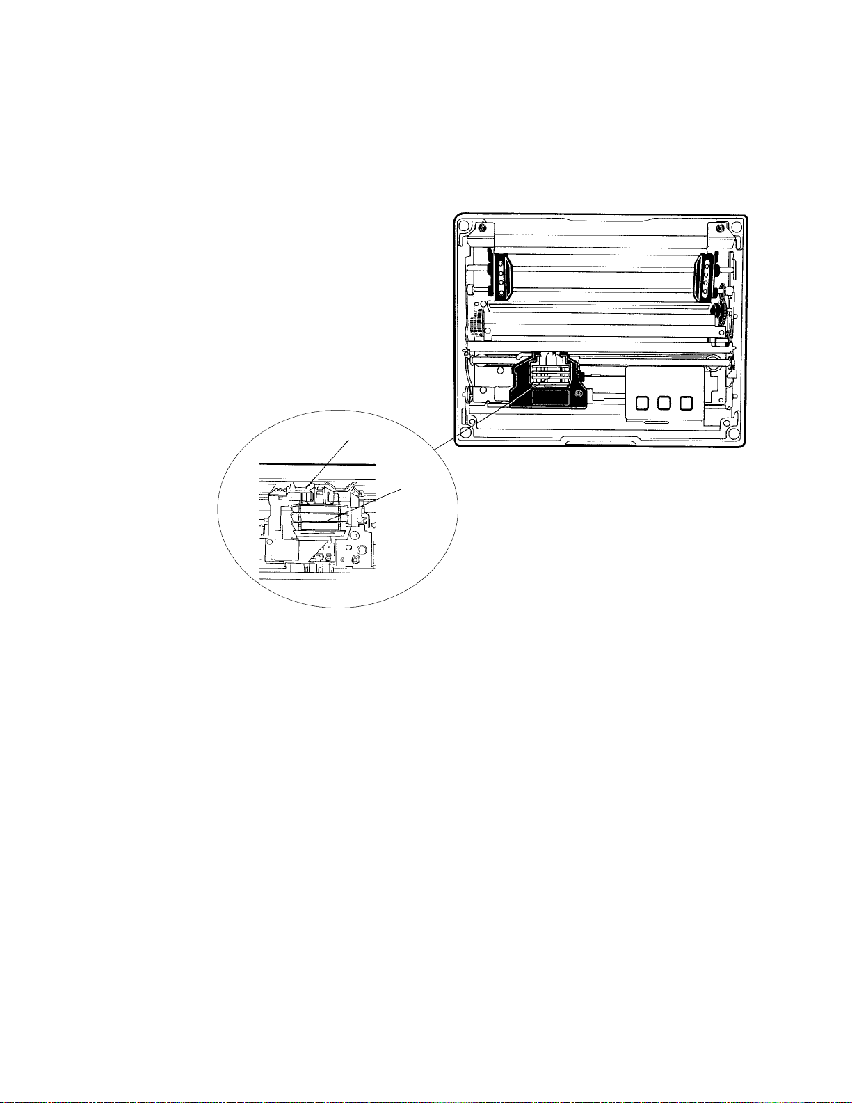
Cleaning the Mask Spring
Look at the mask spring behind the print head. If the mask spring needs to
be cleaned, go on to the next page. If the mask spring appears to be in
good condition, install a new ribbon cartridge as described on page 16.
Mask spring
Print head
This shows the location of the mask spring.
30 6820 Series 80-Column Printer User’s Manual
Page 50

Maintenance—Chapter 3
Do the following to clean the mask spring:
1 Unlatch the print head locking tabs to release the print head, lift the
print head aside, then lift up the paper bail. Donotdetachtheprinthead
unit.
CAUTION: Never use a sharp object, such as pinchers, to clean
between the print head and the platen (rubber roller). This can
damage the mask spring and print head.
2 Remove the clear plastic paper guide that seats the mask spring, if neces-
sary. Use your fingernails to loosen the base of the paper guide, then
pull the paper guide straight up from the printer mechanism.
3 Removethemetalmaskspringfromthepaperguideandcleanwitha
quality cleaner. Replace if damaged.
4 Put the good, clean mask spring into the paper guide and install the pa-
per guide into the printer.
5 Close the paper bail, reinsert the print head, latch the two print head
locking tabs, and install the ribbon.
Print head
locking tabs
Print head
(lifted aside)
Mask spring
Paper bail (raised)
316820 Series 80-Column Printer User’s Manual
Page 51

MaintenanceChapter —3
Changing the Printer Settings
Note: If your printer configuration matches either of the following conditions (manufacturing date or control program version #), then you may
not be able to use your printer control panel to reconfigure the printer.
For units built after March 15, 1999 (line 4 on your self-test report for the
manufacturing date under the “MFG Date” header) or with control program versions greater than 1.67 (line 10 on the self-test report), you do
need to use the configuration utility to change settings. See Chapter 4,
“Using the 6820 Printer Configuration Utility” for information on using the
configuration utility to reflash your printer.
Note: Old printers can be updated with newer control program versions.
The following configuration information applies to units with control program versions 1.67 or older.
On rare occasions, you may need to reconfigure the printer. Use the control panel to enter the following modes and set the printer. Factory defaults
are in bold:
S Protocol Selection
Sets the protocol (NPCP or DTR)
S Configuration
S Autofeed (CR versus CR+LF)
S Bit Rate (9600 bps or 19.2K)
S Zero Print Option (slashed (4) or unslashed (0))
Protocol Selection Mode
Press and hold both the FORM FEED and LINE FEED buttons until you
hear a beep to activate the protocol selection mode. See the Protocol
Binary Sequence table on page 33 for available protocols in the order they
are stored. The PAPER OUT, HEAD JAM, and LOW BATT lights turn
ON or OFF in combinations to indicate which protocol is selected for the
printer. (Factory default is NPCP, all three indicators must be OFF.)
Configuration Mode
Press and hold both the SET PAGE and LINE FEED buttons, for about
four seconds until you hear a beep, to activate the configuration mode.
Setting the Autofeed
S If the LOW BATT indicator stays dark, autofeed is set to CR only
when the printer receives a CR in the input data.
S If the same indicator is lit, autofeed is set to LF+CR and a linefeed is
performed when a CR is received in the input data stream from the
host.
Press LINE FEED to toggle these two autofeed options.
32 6820 Series 80-Column Printer User’s Manual
Page 52

Maintenance—Chapter 3
Selecting the Bit Rate
S If the PAPER OUT indicator is lit, the printer is set for “19.2K.”
S If the same indicator stays dark, the printer is set for “9600 bps.”
Press the FORM FEED button to toggle these bit rates.
Adjusting the Zero Print Option
S If the HEAD JAM indicator is lit, the zero print option is set for the
zero with a slash (4) to appear in printouts.
S If the HEAD JAM indicator stays dark, the zero print option is set for
the zer o without a slash (0) to appear in printouts.
Press the SET PAGE button to toggle between these zero print options.
After selecting configurations, press both SET PAGE and LINE F EED
buttons and listen for a beep to take the printer out of the “Configuration
Mode.” Warm-start the printer to reset it with the new configurations.
Protocol Binary Sequence
PAPER OUT
Protocol
NPCP (factory default) OFF OFF OFF
Reserved OFF OFF ON
Reserved OFF ON OFF
Reserved OFF ON ON
DTR no parity ON OFF OFF
DTR odd parity ON OFF ON
DTR even parity ON ON OFF
IrDA ON ON ON
Indicator
HEAD JAM
Indicator
LOW BATT
Indicator
Repeatedly press the LINE FEED button to increment the light sequence
to the protocol of choice (NPCP to IrDA).
Example
If the printer is set for “NPCP” (OFF, OFF, OFF), press the LINE FEED
button four times to increment the protocol selector to the “DTR no parity” protocol (ON, OFF, OFF).
Repeatedly press the SET PAGE button to decrement the light sequence to
the protocol of choice (IrDA to NPCP).
Example
If set for “DTR no parity” protocol (ON, OFF, OFF), press the SET
PAGE button four times to return to “NPCP” (OFF, OFF, OFF).
After you have selected the protocol, press both the FORM FEED and
LINE FEED buttons and listen for a beep. This takes the printer out of
the Protocol Selection Mode. Warm-start the printer to reset it with the
new protocol.
336820 Series 80-Column Printer User’s Manual
Page 53

MaintenanceChapter —3
34 6820 Series 80-Column Printer User’s Manual
Page 54

Using the 6820 Printer
4
The IntermecR6820 Printer Configuration Utility is run on a host computer to manipulate the configuration of a 6820 Printer flash memory.
This chapter describes how to install and use the configuration utility. Before using the configuration utility, you must connect your host computer
to your printer, go to page 37 for instructions.
Configuration Utility
356820 Series 80-Column Printer User’s Manual
Page 55

—
Using the 6820 Printer Configuration Utility
Chapter
4
Font Modules
Intermec Technologies provides the following font modules for your 6820
Printer:
S NFT00000.MOD — Default International, 4820 compatible
S NFT00437.MOD — IBM/Microsoft compatible Code Page 437
S NFT00932.MOD — JIS Japanese
S NFT00936.MOD — GB2312 Chinese Simplified
S NFT00949.MOD — KSC5601 Korean
S NFT00950.MOD — Big 5 Traditional Chinese
Note: See Appendix C, “PrinterFontTestJobs,” for sample print jobs.
Note that there are three versions of the default font module
(NFT00000.MOD) — Arabic, Turkish, and International. A ny one version of this module, but not all three versions, can appear in the 6820
Printer Configuration Utility “FONTS” directory and install on the 6820
Printer. The International version of this font module is automatically
placed in the “FONTS” directory when the Configuration Utility is
installed on the host computer.
All three versions are included on the toolkit CD as follows:
S The Arabic version is included in the “Default Fonts\Arabic” directory.
S The Turkish version is in the “Default Fonts\Turkish” directory.
S The International version is in the “Default Fonts\International” direc-
tory.
Once the Configuration Utility is installed on the host computer, any of
these default font modules can replace the existing default font module
(NFT00000.MOD). Copy the desired default font from the appropriate
toolkit CD default fonts directory to the “FONTS” directory of the Configuration Utility. The Configuration Utility has access to any font modules in this “FONTS” directory.
For Windows 95 and Windows 98 users:
If the default installation process was followed, the configuration utility
“FONTS” directory is located at “6820PRTR\TOOLKIT\FONTS”
where “6820PRTR” is replaced by the actual directory in which you chose
to extract the files.
For Windows 2000 and Windows XP users:
If you followed the default installation process, the Configuration Utility
“FONTS” directory is located at “Program Files\Intermec\6820 Printer
Configuration Utility\FONTS.”
Note: Do not rename the font files in the “FONTS” directory. If you do
so, the files names will not match the data in these files and the fonts will
not work as expected.
36 6820 Series 80 -Column Printer User’s Manual
Page 56

Connecting to the Printer
Connect your printer to your desktop computer via a serial cable. The serial COM Port connector on either your Fixed Mount Printer or your Portable Printer is on your printer mechanism, the same side as the green
thumb wheel.
Chapter
—
Using the 6820 Printer Configuration Utility
4
Printer
mechanism
(raised)
COM Port connector
Be sure to locate and disconnect the gray terminal holder ribbon cable
connector from the floor of the printer cavity. The cable is located behind
the printer mechanism on the same side as the green thumb wheel and is
the one that is not attached to the printer mechanism.
Disconnect this terminal holder
ribbon cable from the floor of
the printer cavity
Intermec Technologies provides a printer configuration utility based on
several operating systems that may be used on your host computer. Below
are the operating systems for which the configuration utility is written. Select your operating system, then go to that page to begin instructions for
your particular configuration utility.
Reset button
Ignore this cable attached
to the printer mechanism.
S If your host computer has either Windows 95 or Windows 98, go to
page 38 for instructions.
S If your host computer has Windows 2000 or Windows XP, go to page
53.
6820 Series 80-Column Printer User’s Manual
37
Page 57

—
Using the 6820 Printer Configuration Utility
Chapter
4
Instructions for Windows 95 or Windows 98
These instructions apply to desktop computers running either Windows
95 or Windows 98 operating systems.
Installation
All files necessary to configure the 6820 Printer are located in the toolkit,
including the Configuration Utility application program,
RPGPCONF.EXE, and the initialization file, RPGPCONF.INI. The initialization file is used by the Configuration Utility to specify the location
and names of font and printer control program files.
To set up your host computer to use the Configuration Utility, extract the
toolkit files from the self-extracting archive file, NPTK6820.EXE. First,
create a directory, on your host computer, with an appropriate name for
the Configuration Utility files. The name of this directory is your choice.
You could choose to have the files extracted at the root directory of your
host computer. However, the directory used in the example below is
\6820PRTR. Execute the self-extracting file from the target directory while
specifying the path to NPTK6820.EXE in the command line.
Upon executing NPTK6820.EXE, a “TOOLKIT” subdirectory is created,
as well as other associated subdirectories, as shown in the diagram below.
The Configuration Utility application program and the initialization file
are extracted to the TOOLKIT subdirectory. Other files are extracted to
the other subdirectories created by the archive file.
6820PRTR
This is the directory where
you executed NPTK6820, to
extract the configuration
utility files.
Configuration File Support
The configuration utility allows the user to generate custom configuration
files. These files have the file name extension of “.PCF”, and they reside in
the directory specified in the initialization file. See DEFAULT.PCF, in the
PCFS directory for an example.
TOOLKIT
6820SYS
DOS
FONTS
PCFS
Configuration Utility Operation
A configuration consists of a list of fonts, some parameter settings, and optionally, a printer control program.
When the utility is active, it holds a configuration in memory. This is
called the “working configuration”. Initially, this working configuration
38
6820 Series 80-Column Printer User’s Manual
Page 58

—
Using the 6820 Printer Configuration Utility
Chapter
4
has no fonts, the parameters are set to the default values, and there is no
printer control program in memory. You should consider the working configuration as temporary and lost when you exit from the utility.
The Configuration Utility’s main menu offers you various ways to manipulate the working configuration. You can overwrite this working configuration with a previously saved configuration, stored either in a disk file
on the computer or in the 6820 Printer itself by using one of the Load
Printer C onfiguration options. You can modify the working configuration
by using one of the Modify Printer Configuration options. Once the
working configuration is loaded and modified, you can save this to either a
disk file or the printer by using one of the Save Printer Configuration options.
In addition to the various Load, Modify, and Save options, a Defaults option is provided, which allows you to restore the printer to a default configuration with a single option.
Starting the Program
When you run RPGPCONF.EXE, the first screen you see is like the following. Click OK to continue to the Main Menu.
Main Menu
The following options are available on the Main Menu.
S Use Load Printer Configuration to load an existing configuration. Load
either from disk or from the printer.
S Use Modify Printer Configuration to review or modify the working
configuration, or include the printer control program in the currently
loaded configuration.
S Use Save Printer Configurations to save a configuration file to disk or
download the working configuration to your 6820 Printer.
S Use Defaults to restore the printer to its default configuration.
6820 Series 80-Column Printer User’s Manual
39
Page 59

Chapter
—
Using the 6820 Printer Configuration Utility
4
Note that when the Main Menu is first displayed, the Save Printer Configuration options are grayed out, prohibiting selection of those options
until a configuration is loaded or modified.
Exit from the Configuration Utility Program
If you click Exit, a message appears to prompt whether you want to exit.
Click No to return to the Main Menu. Click Yes to exit the program.
Load Printer Configuration
This set of options allows you to load configuration information from disk
(on the host computer) or from the printer (connected to the host computer).
Load Configuration from File option
This option, selected from the Main Menu, allows you to load a configuration file from one of the drives on your host computer.
Click From File from the Main Menu to access the File, Open window.
Here, you can open a configuration parameters file from one of your host
computer drives. It operates like the File, Open on a standard Windows
program.
40
6820 Series 80-Column Printer User’s Manual
Page 60

—
Using the 6820 Printer Configuration Utility
Chapter
4
Canceling the Operation
Click Cancel to return to the Main Menu without selecting a file to open.
Selecting a File Name
You can select the drive, directory, and file name with your pointing device, using standard MS Windows file selection methods. If you want to
enter text for a file name, you can do this with the alpha keyboard, or use
your host computer keyboard. Click Alpha to access the alpha keyboard
described on page 52.
Loading the Selected File
After selecting a configuration file to load, click OK. If the selected file
does not exist, you see an error message similar to the following. Click OK
to return to the Main Menu without loading a file.
If the file does exist, you see a warning that loading the selected file will
overwrite your working configuration, as shown in the message box below.
Click OK if this is acceptable, otherwise click Cancel to return to the
Main Menu without loading a file.
After clicking OK, the configuration from the selected file is loaded into
memory and becomes the current working configuration. If this load is
successful, a message similar to the one shown below is displayed. Click
OK to return to the Main Menu.
6820 Series 80-Column Printer User’s Manual
41
Page 61
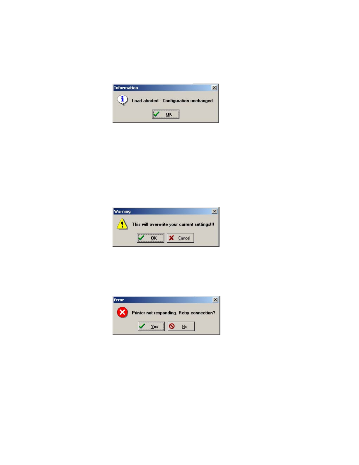
Chapter
—
Using the 6820 Printer Configuration Utility
4
However, if the working configuration is not replaced successfully with the
configuration from the selected file, an error message is displayed informing you that it was not successful, as shown below. Click OK to return to
the Main Menu without loading a file.
Load Configuration from Printer
This option, selected from the Main Menu, loads a configuration from the
6820 Printer. Click From Printer from the Main Menu to display a warning message (as shown below) and indicate that the printer’s configuration
will overwrite the working configuration. Click OK to overwrite the configuration, otherwise click Cancel to return to the Main Menu without
loading the printer’s configuration.
If you click OK, a message is then displayed prompting you to reset the
printer. If the connection is not successful, after approximately 20 seconds,
the following message is displayed.
If you click Yes, repeat the previous steps, starting with Attempting a Con-
nection to the Printer.
42
6820 Series 80-Column Printer User’s Manual
Page 62

—
Using the 6820 Printer Configuration Utility
Chapter
4
If you click No, an error message appears (as shown below) is displayed
informing you that the configuration was not loaded. Click OK to return
to the Main Menu without loading the printer’s configuration.
Connection Successful
If the connection to the printer is successful, then no user intervention is
required throughout the remainder of this operation. The Get From Printer function is initiated, and the Configuration Utility copies the printer
configuration into the working configuration.
This utility communicates with the 6820 Printer to find out the current
parameter settings and which font modules are loaded. The name, version,
and size of these font modules are then displayed on the Get From Printer
screen.
If the operation is successful, you are returned to the Main Menu and the
printer configuration is loaded as the w orking configuration. You can view
or modify the working configuration by selecting a Modify Printer Con-
figuration option.
Modify Printer Configuration
This set of options allows you to view or change a working configuration,
including adding fonts from disk (on the host computer), deleting printer
fonts, and changing parameters settings.
6820 Series 80-Column Printer User’s Manual
43
Page 63
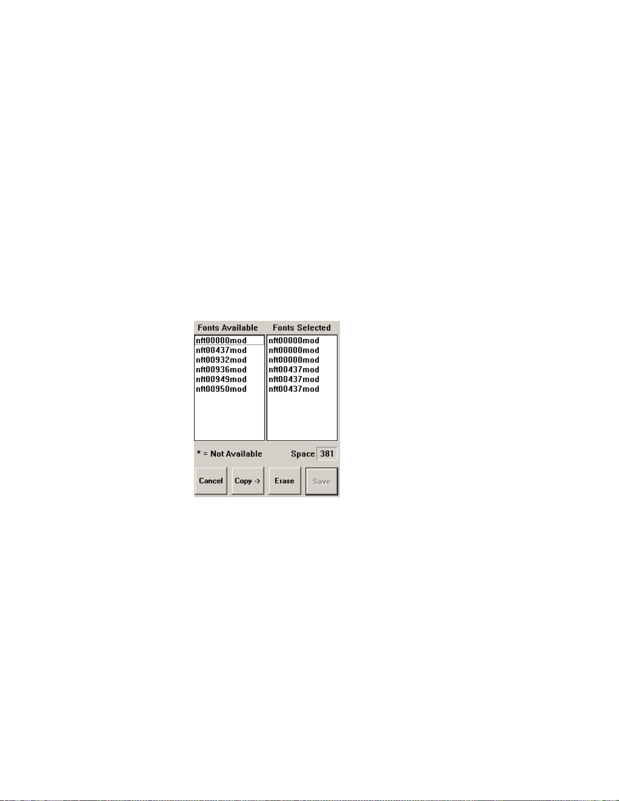
Chapter
—
Using the 6820 Printer Configuration Utility
4
Include C ontrol Program is a switch that determines whether to include
the printer control program when saving the working configuration to the
printer. Click this box to change the setting. When checked, the control
program is included the next time you save the printer configuration.
Generally, you only need to update the control program as new versions
become available. The control program is named NPFL6820.MOD.
Font Selection
This option, selected from the Main Menu, selects fonts that are available
on disk, or deletes existing fonts. A variety of different international fonts
are also available in the toolkit for the 6820 Printer.
Clicking Fonts from the Main Menu takes you to Font Selection where
you can perform operations related to font files,. The Fonts Available list
shows font files that are available on disk. The Fonts Selected list show
fonts that are in the current printer configuration.
Note that Save is grayed out, prohibiting that selection, until either new
fonts are selected, or fonts are removed from the Fonts Selected list.
44
Copying Font Files
To select font files, highlight the font files in the Fonts Available list, with
your pointing device. You can highlight several files at one time, using
conventional Windows selection methods. Then click Copy to copy those
font files to the Fonts Selected list.
However, if you attempt to copy fonts from the Fonts Available list when
these fonts already exist in the Fonts Selected list, the following error message is displayed, once for each of the duplicate fonts (where the current
font file name is listed in place of NFT00000.MOD).
Click OK to close the error message and not copy the font to the Fonts
Selected list. If there are two or more duplicate fonts, the cycle repeats until an error message is displayed for each of the duplicate font files.
The font file names become unhighlighted, you remain in the Font S election window, and the duplicate fonts are not copied to the Fonts Selected
list.
6820 Series 80-Column Printer User’s Manual
Page 64

—
Using the 6820 Printer Configuration Utility
Chapter
4
Deleting Font Files
To avoid the problem of exceeding flash memory, you can delete fonts in
the printer flash, from the Fonts Selected list. To do this, select the font
names you want to delete in the Fonts Selected list, then click Erase to
clear the names from the Fonts Selected list.
Space Remaining in Flash
The Space Selection box, below the Fonts Selected list, displays the space
remaining in flash (in kilobytes), based on fonts currently selected. When
this number is negative, it means the available space in flash is less that the
size of the selected fonts. Delete some fonts before saving the rest.
Saving the Selected Fonts
Note that Save is initially grayed out, disabling its use. Once the Fonts Selected list is changed, Save is enabled (no longer grayed out).
Fontsmarkedwithanasterisk(*),intheFonts Selected list, are currently
in printer flash, but not found on disk, and are lost when flash is updated
from disk (Save to Printer option).
When Save is clicked, and there is enough space in printer flash memory
for the fonts in the Fonts Selected list, the working configuration is updated with the selected fonts. The amount of printer flash memory to
spare, after being loaded with the selected fonts, is shown (in kilobytes) in
the Space box. As long as this number is not negative, there is enough
space for the selected fonts.
However, if you attempt to save fonts and there is not enough space in
printer flash memory, the following error message is displayed. Click OK
to return to the Font Selection window and delete fonts in the Fonts Se-
lected list.
6820 Series 80-Column Printer User’s Manual
45
Page 65

Chapter
—
Using the 6820 Printer Configuration Utility
4
Canceling the Operation
Click Cancel to return to the Main Menu without making any changes. If
you have not made any changes to the Fonts Selected list, you return to
the Main Menu.
However, if you have already made some changes to the Fonts Selected
list, a confirmation message appears, similar to that shown below. Click
OK to return to the Main Menu with changes made to the Fonts Selected
list discarded. Click Cancel to remain in the Font Selection window.
Parameters Selection
This option, selected from the Main Menu, allows you to review or modify
the working configuration.
Click Parameters from the Main Menu to access the Parameters window
where you can modify any of the parameters that are not grayed out. Default parameter values are marked with an asterisk (*).
Modifying Parameters
To modify the configuration, select parameters on this screen using your
pointing device.
46
Required for Bluetooth — Convert the Printer to E pson DTR Mode
Those using Bluetooth must switch the 6820 Printer from the Norand
Portable Communications Protocol (NPCP) mode to the Epson DTR
mode with the baud rate set to “19.2K” and the parity set to “None.”
Note: The 6820 Bluetooth adapter does not support any other settings.
6820 Series 80-Column Printer User’s Manual
Page 66

—
Using the 6820 Printer Configuration Utility
Chapter
4
Note: If your version of the Configuration Utility has a 38.4K bit rate
selection, ignore that selection. If selected, it defaults to 19.2K bps. On
future releases, the 38.8K bit rate will not s how on the display.
Note: If your version of the Configuration Utility has an XON/XOFF
selection, ignore that selection. If selected, it defaults to DTR. On future
releases, the XON/XOFF protocol will not show on the display.
Saving Parameters
Clicking Save updates the working configuration and returns you to the
Main Menu.
Canceling the Operation
Click Cancel to return to the Main Menu without modifying any configuration parameters.
Save Printer Configuration
These options allow you to save the working configuration to disk or to
printer.
Save is initially grayed out in the Main Menu, and cannot be used until a
configuration is either loaded or modified.
Save to File
This option, selected from the Main Menu, allows you to select the drive,
directory, and file name with your pointing device, using standard Windows file selection methods.
Click To File from the Main Menu to access the File Save As window
(similar to the File Open window). This option allows you to save the
working configuration to a disk file.
6820 Series 80-Column Printer User’s Manual
47
Page 67

Chapter
—
Using the 6820 Printer Configuration Utility
4
Choosing File Name and Location on Disk
You can select the drive, directory, and file name with your pointing device, using standard MS Windows file selection methods. If you want to
enter text for a file name, you can do this with the alpha keyboard, or use
your host computer keyboard. Click Alpha to access the alpha keyboard
described on page 52.
Saving the Configuration to Disk
After you have selected the drive, directory, and file name, click OK to
save the configuration file. If a file by the same name exists, the following
confirmation message is displayed, informing you that if you continue it
will overwrite the existing file.
Click Cancel to return to the Main Menu without the working configuration saved to a file.
Click OK for the File Save As operation to continue. The following information is displayed assuring you that the working configuration was successfully saved to disk. Click OK to return to the Main Menu.
Canceling the “Save to File” Operation
From the File, Save As window, if you click Cancel, this aborts the Save to
File operation, and returns you to the Main Menu without saving the
working configuration.
48
6820 Series 80-Column Printer User’s Manual
Page 68

—
Using the 6820 Printer Configuration Utility
Chapter
4
Save to Printer
This option, selected from the Main Menu, allows you to send the working configuration to your 6820 Printer.
When To Printer from the Main Menu is clicked, a warning message (as
shown below) is displayed.
This means that the working configuration is copied into flash memory, in
your 6820 Printer, and overwrites the current configuration settings that
are in your printer. Click OK to for the system to connect to the printer
and transfer the configuration, or click Cancel to return to the Main Menu
without updating the printer.
Attempting a Connection to the Printer
After clicking OK, a message is displayed, informing you that the system is
attempting to establish connection with the printer. At this point you
should connect a serial cable (P/N: 226-270-001) between your host computer and the printer (if not already connected), then reset the printer.
Connection Failed
If the connection is not successful after the predetermined period of time
(approximately 20 seconds), the following message is displayed.
Click Yes to repeat the previous steps above (starting with Attempting a
Connection to the Printer), else click No. An error message (as shown be-
low) is displayed informing you that the configuration was not saved.
Click No to return to the Main Menu without updating the printer.
6820 Series 80-Column Printer User’s Manual
49
Page 69

Chapter
—
Using the 6820 Printer Configuration Utility
4
Connection Successful
If the connection is successful, the following screen is displayed, the Send
to Printer function is initiated, and the printer’s configuration is updated
to match the working configuration.
This screen displays the progress made while updating the printer’s configuration. Upon completion of this operation, the Total Transfer bar reaches 100%, and you return to the Main Menu.
Save Defaults to Printer
Click Save to Printer on the Main Menu to load the default configuration
file, DEFAULT.PCF, and save it to the printer. This combines the operations of the [from file], the selection of the DEFAULT.PCF file, and the
[to printer] into a single button. The following message appears stating
that the working configuration is overwritten. Click Cancel to return to
the Main Menu without loading the default configuration file.
50
6820 Series 80-Column Printer User’s Manual
Page 70

—
Using the 6820 Printer Configuration Utility
Chapter
4
If you click OK, and if the default configuration file is not successfully
loaded into the working configuration (such as an illegal directory), then
the following error message appears. Click OK to return to the Main
Menu without loading a file.
If the default configuration file is successfully loaded into the working configuration, a message, as shown below, is displayed. Click OK to continue
with the Restore Defaults to Printer operation.
Attempting a Connection to the Printer
If the default configuration was successfully loaded into working configu ration, then a message is displayed, prompting you to reset the printer.
Connection Failed
If the connection is not successful, after approximately 20 seconds, the following message is displayed.
Click Yes to repeat the previous steps, above, starting with Attempting a
Connection to the Printer. If you click No, an error message (as shown be-
low) is displayed. Click OK to return to the Main Menu without saving
the default configuration to the printer.
6820 Series 80-Column Printer User’s Manual
51
Page 71

Chapter
—
Using the 6820 Printer Configuration Utility
4
Connection Successful
If the operation was successful, your 6820 Printer is now set to the default
configuration in flash memory, and you are returned to the Main Menu.
Default Printer Settings
These settings are used when Restore Defaults to Printer is selected:
Zero Print Option Slash all zeros (zeros are printed with a slash)
Autofeed Configuration CR (carriage return at end of line without line feed)
Protocol NPCP
Parity N/A (for NPCP)
Bit Rate 19.2K
For other printer defaults, refer to the Printer Defaults paragraph in Appen dix B, “Cross-Reference Tables.”
Alpha Keyboard
The Alpha button, on either the File Open window or the File Save As
window, brings up the alpha keyboard onscreen for you to enter text.
52
Returning the File Name to the Previous Dialog Window
After selecting all of the needed text, click Save to return the text to the
window where needed. Click Cancel to exit without saving the text. The
following confirmation message appears. Click OK to return to the previous window without the entered text, or click Cancel to stay with the
alpha keyboard.
6820 Series 80-Column Printer User’s Manual
Page 72

—
Using the 6820 Printer Configuration Utility
Chapter
4
Instructions for Windows 2000 or Windows XP
These instructions apply to desktop computers running either Windows
2000 or Windows XP operating systems.
Installation
All files necessary to configure the 6820 Printer are located on the CD for
the 6820TKCD toolkit, including the 6820 Printer Configuration Utility
applicationprogram,PCONFIGAPP.EXE.Tosetupyourhostcomputer
to use the Configuration Utility, do the following:
1 Insert the toolkit CD in your host computer.
2 From your desktop, use your Explorer application to view the contents
of the tookit CD.
3 Double-click the SETUP.EXE executable file, then click Next from the
Welcome screen to continue.
6820 Series 80-Column Printer User’s Manual
53
Page 73

Chapter
—
Using the 6820 Printer Configuration Utility
4
4 If you wish to change the default location of this installation, click
Browse to change the destination. If this installation is for anyone who
uses this desktop computer, select Everyone near the bottom of this
screen. Click Next to continue.
If you wish to know the amount of space required for the configuration
utility, click Disk Cost for the following screen. Click OK to close and
return to the installation screens.
54
6820 Series 80-Column Printer User’s Manual
Page 74

—
Using the 6820 Printer Configuration Utility
Chapter
4
5 Click Next to verify this installation, click Back to adjust the informa-
tion in the previous screen, or click Cancel to exit this installation.
6 A progress screen, followed by an Installation Complete screen finishes
this installation. Click Close to exit the installation.
6820 Series 80-Column Printer User’s Manual
55
Page 75
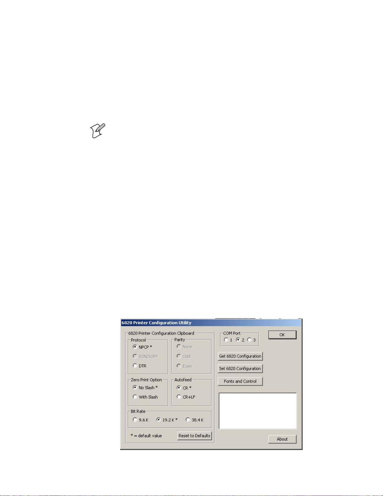
—
Using the 6820 Printer Configuration Utility
Chapter
4
If the default location was not changed in step 4 on the previous page, the
“Program Files\Intermec\6820 Printer Configuration Utility” subdirectory
is created. The Configuration Utility application program and applicable
DLL files are extracted to this subdirectory.
After installation, from your desktop, click Start > Programs > Intermec >
6820 Printer Configuration Utility to access the 6820 Printer Configuration Utility executable and related documentation.
Configuration Utility Operation
Note: If your 6820 Printer has a Bluetooth adapter, its RS-232 line driver
canbeincontentionwiththeconfigurationport’sconnectedprogramming PC. Disconnect the Bluetooth adapter before continuing.
This configuration consists of a list of fonts, some parameter settings, and a
printer control program.
When the utility is active, it holds a configuration in memory. This is
called the “configuration clipboard.” Initially, this c onfiguration has parameters set to their default values. Consider the contents of the configuration clipboard as temporary and lost when you exit from the utility.
With the Configuration Utility, you can view the configuration stored in
your 6820 Printer using the Get 6820 Configuration button. You can
configure or modify the printer settings in your printer using the Set 6820
Configuration button.
In addition, you can use the Reset to Defaults button to reset the c onfiguration clipboard to the recommended printer configuration. Note that this
button does not send the default configuration to the printer.
Starting the Program
From your desktop, click Start > Programs > Intermec > 6820 Printer
Configuration Utility > PConfigApp.exe to access the 6820 Printer Con-
figuration Utility.
56
6820 Series 80-Column Printer User’s Manual
Page 76

—
Using the 6820 Printer Configuration Utility
Chapter
4
COM Port
This utility is flexible in which COM Port to use to communicate with
yourprinter.IfCOMPort1isnotavailableorisinusebyanotherapplication, select another COM Port with which to connect to your printer.
Establishing a Communication with the Printer
Click either the Get 6820 Configuration or the Set 6820 Configuration
button to open communications with the printer.
1 The “Opening COM Port x to printer . . . ” message appears in the text
box of your utility. The “x” in the message indicates to which COM
Port your utility is set.
2 When the “Press Reset on the printer” message appears in the text box,
press the reset button on your printer mechanism.
3 As soon as successful communication is established between your desk-
top computer and your printer, an “Opening COM Port x to printer. . .
Done.” message appears in the text box.
Note: If an “Unable to open COM Port x to printer” message appears in the
text box, as shown in the previous sample, another software application
may be using the selected COM Port. Either select another COM Port or
disable the software application using the COM Port in question. See page
61 for more errors.
6820 Series 80-Column Printer User’s Manual
57
Page 77

Chapter
—
Using the 6820 Printer Configuration Utility
4
Get 6820 Configuration
To view the settings on your 6820 Printer, do the following:
1 Click Get 6820 Configuration to initiate communication.
2 The “Getting printer parameters . . . ” message appears in the text box.
3 When finished retrieving information from the printer, the “Getting
printerparameters ...Done” message replaces the message described in
step 2. This message indicates parameters were successfully obtained
from the printer and the utility settings reflect your printer settings.
4 Either go to “Set 6820 Configuration” in the next paragraph; or click
OK to close the utility, then detach the serial cable.
Set 6820 Configuration
The settings in the configuration clipboard a re what is sent into your
printer when you change its configuration.
1 In the configuration clipboard, if necessary, select what settings are re-
quiredforyourprinter.To undo your selections and return them to their
defaults, click Reset to Defaults.
2 Click Set 6820 Configuration to initiate communication. The “Setting
printer parameters . . .” message appears in the text box of your utility.
3 Once settings in your printer are changed, the “Setting printer parameters
...Done” message replaces the message described in step 2.
Note: If the parameters cannot be set, a “Unable to set p rinter parame-
ters” message is shown. This indicates the connection broke down be-
tween your desktop computer and your printer.
4 Click OK to close the utility, then detach the serial cable.
Required for Bluetooth — Convert the Printer to E pson DTR Mode
Those using Bluetooth must switch the 6820 Printer from the Norand
Portable Communications Protocol (NPCP) mode to the Epson DTR
mode with the baud rate set to “19.2K” and the parity set to “None.”
Note: The 6820 Bluetooth adapter does not support any other settings.
58
6820 Series 80-Column Printer User’s Manual
Page 78

—
Using the 6820 Printer Configuration Utility
Chapter
4
Fonts and Control
Click Fonts and Control from the 6820 Configuration Utility to update
the fonts stored in your printer or to update the printer control program.
The Fonts Available for Update list shows font files that are available. The
Fonts Selected for Update list show fonts that are to go to the printer.
Get Printer Fonts
To learn what fonts are currently in your printer, click Get Printer Fonts,
then wait for the information to appear in the text box in the bottom right
corner of the dialog. Below is a sample screen.
6820 Series 80-Column Printer User’s Manual
59
Page 79

Chapter
—
Using the 6820 Printer Configuration Utility
4
Copying Font Files
To select font files, highlight the font files in the Fonts Available for Update list. You can highlight several files at one time. Then click the right
arrow pointing to the Fonts Selected for Update list to copy the selected
font files to this list. Below is a sample screen.
If you select enough fonts that go over the space allowed, an error message
will appear. Click OK to close the error message and not copy the font to
the Fonts Selected for Update list. If there are two or more fonts that exceed the space allowed, this message repeats until an error message is displayedforeachofthefontfilesthatwentoverthespaceallowed.
Space in Flash
The Space Needed information shown beneath the Fonts Available for
Update list indicates the total space required (in bytes) for all of the fonts
in the list. The Space Remaining information listed below the Fonts Selected for Update list displays the space remaining in the printer, given the
fonts in the Selected list.
Update Printer
This button updates the printer fonts and the control program depending
on the options selected on the d ialog. Note that if the Selected list is empty
and the Include control program update is not checked, a “Nothing selected
for update” message appears in the text box.
S Formats the printer flash for font updates and writes new font files to
the printer for any fonts in the Selected list.
Click the top, right arrow to copy selected font files from the Fonts
Available for Update list to the Fonts Selected for Update list. Click
the bottom, left arrow to remove any selected files from the Fonts Se-
lected for Update list.
60
6820 Series 80-Column Printer User’s Manual
Page 80

—
Using the 6820 Printer Configuration Utility
Chapter
4
Click Update Printer to update the fonts in the printer with those in
the Fonts Selected for Update list. The Update progress: bar indicates
the progress as the control program or fonts are written to the printer.
S The Include program control update box determines whether to in-
clude the printer control program when updating the printer. Check
this box to update the setting and include the control program the next
time you update the printer configuration.
Generally, you only need to update the control program as new versions
become available. The control program is named NPFL6820.MOD.
Default Printer Settings
The following settings are the defaults for your 6820 Printer:
Zero Print Option Print zeros without a slash
Autofeed Configuration CR (carriage return at end of line without line feed)
Protocol NPCP
Parity N/A (for NPCP)
Bit Rate 19.2K (19200)
For other printer defaults, refer to the Printer Defaults paragraph in Appen dix B, “Cross-Reference Tables.”
Error Messages
There are three cases where the computer may not connect to the printer.
Here are the three cases and error messages. Note that “x” indicates the
number assigned to the COM Port in question.
6820 Series 80-Column Printer User’s Manual
61
Page 81

Chapter
—
Using the 6820 Printer Configuration Utility
4
Timeout Error
The timeout error may occur due to either of these situations:
S The printer was not reset in the time allowed.
S The COM port exists on the desktop computer but nothing is con-
nected to the port.
Error Message:
Unable to open COM port x to printer. Printer not reset
within the time allowed or printer not connected to COM
port x.
Port Not Found Error
The COM port does not exist. The particular COM port is identified in
the error message.
Error Message:
Unable to open COM port x to printer. COM port x cannot
be found.
Access Denied Error
The COM port exists but a connection with the printer is not established.
The particular COM port is identified in the error message.
Error Message:
Unable to open COM port x to printer. Access to COM
port x is denied. Close applications using COM port x
or try another port.
About the Configuration Utility
Click About to learn about your version of the 6820 Configuration Utility. When done, click OK to return to the utility.
Bluetooth Adapter
Note: If your 6820 Printer is to use a Bluetooth adapter, be sure to connect this adapter after you exit the Configuration Utility, thus finish reconfiguring the 6820 Printer fonts.
62
6820 Series 80-Column Printer User’s Manual
Page 82

Control Code Definitions
5
This chapter contains a set of control code definitions and specifications
for page layout for the 6820 Printer. These c ontrol code definitions are
organized by categories of functions.
To locate control codes easily, several methods have been provided:
S Alphabetically organized (complete list)—
refer to the Control Codes & Escape Sequences Index table in Appendix B,
“Cross-Reference Tables.” Locate the index for the control code, and turn
directly to that page.
S Numeric order (single character codes only)—
refer to the Single Character Control Code Definitions table in Appendix
B, “Cross-Reference Tables.“ Locate the index for the control code, and
turn directly to that page.
S Numeric order (complete list)—
refer to the Escape Sequences Quick Reference table in Appendix B,
“Cross-Reference Tables” and look up control codes by their actual code
values.Locatetheindexfortheescapesequence,andturndirectlyto
that page.
636820 Series 80-Column Printer User’s Manual
Page 83

—
Control Code Definitions
Chapter
5
Control Code Definitions
Buffers
I/O Buffer
All characters and control codes received by the printer are stored in this
buffer. Characters and controls codes are read from this buffer and acted
upon to form the print buffer. Characters are removed from the I/O buffer
as they are processed.
Print (image) Buffer
All characters go through this buffer on their way to the printed page. This
buffer contains the graphic image of the dots to print, from which characters are rendered. It is cleared when its contents are printed.
Special Notations
The following information defines notations included in the format definitions of the escape sequences, throughout this section.
Notation Description
(0) Used in the ASCII column of any of the Format definitions, indicates that its value can only be zero
(and not the character “0”). For example: S elect Top-Down Printing ESC US (0).
(1) Used in the ASCII column of any of the Format definitions, indicates that its value can only be one
(and not the character “1”). For example: Select Bottom-Up Printing ESC US (1).
* When a number (at the end of an escape sequence) is marked with an asterisk, then either the value
corresponding to that number or the value of the string character can be used for that number.
For example, if 1* is shown, then either the value (1), or the value of the string character (decimal:
49, hex: 31) can be used.
NUL
T
he NUL character is represented in the Dec column as 0, in the Hex column as 00, and in the
ASCII column as NUL.
General Printer Control Functions
Backspace
The print buffer is emptied. The print head is moved to the left one character space (using the current pitch). This can be performed to, but not
beyond, the left margin setting. The backspace is ignored if justification of
right, full, or centered is selected.
Format
Decimal Hex ASCII
8 08 BS
The backspace control code (BS) is not reliable when text contains different character pitches. For reliable backspacing, use the escape sequence
(ESC “\”), Set Relative Print Position.
64 6820 Series 80 -Column Printer User’s Manual
Page 84

—
Control Code Definitions
Chapter
5
Beeper
The printer’s sounding device produces a beep sound for approximately
1/10 of a second.
Format
Decimal Hex ASCII
7 07 BEL
Cancel Line
All of the characters currently in the print buffer are discarded. Current
print position is set to left margin. Text already printed cannot be canceled.
Format
Decimal Hex ASCII
24 18 CAN
Carriage Return
The print head is repositioned at the start of the print line (usually at the
left margin), and repositions the pointer to the start of the print buffer,
after printing all data in the buffer. Also, all of the “one line” functions are
reset, such as bold, double-strike, double-wide, or unidirectional printing.
Format
Decimal Hex ASCII
13 0D CR
Note: You can add an automatic line feed with a configuration item (see
Configuration Parameters in Chapter 7, “Troubleshooting and Diagnostics”).
Delete
The last character in the print buffer is deleted. This functions only in left
justification.
Format
Decimal Hex ASCII
127 7F DEL
Form Feed
The contents of the print buffer is printed, the print buffer is cleared, and
the paper is advanced to the top of the next page (Top of Form), according
to the current page length setting. The carriage position is moved to the
start of the line.
Format
Decimal Hex ASCII
12 0C FF
6820 Series 80-Column Printer User’s Manual
65
Page 85

Chapter
—
Control Code Definitions
5
Select Half-Speed Printing
Half-speed mode is turned on to provide quiet printing, and more accurate
print positioning during text mode printing.
Format
Decimal Hex ASCII
27 115 1* 1B 73 01* ESC “s” 1*
Cancel Half-Speed Printing
Half-speed mode is turned off (factory default), and continues with normal
speed printing.
Format
Decimal Hex ASCII
27 115 0* 1B 73 00* ESC “s” 0*
Set Inactivity Time for Sleep Mode
The time period, for which the printer waits during inactivity before it
goes into low-power mode, is set (in n seconds). The factory default is 10
seconds.
Format
Decimal Hex ASCII
27 122 n 1B 7A n ESC “z” n
Line Feed
Perform Line Feed
The contents of the print buffer is printed, then cleared, and the character
count is reset to zero; then the print head advances to the next print line,
using the current spacing. The position of the carriage is not affected and a
carriage return is not executed.
Format
Decimal Hex ASCII
10 0A LF
Perform n/216-inch Line Feed
The paper to immediately advanced n/216 of an inch. This does not affect
subsequent line feeds. Range of n is 0–255.
66
Format
Decimal Hex ASCII
27 74 n 1B 4A n ESC “J” n
6820 Series 80-Column Printer User’s Manual
Page 86

—
Control Code Definitions
Chapter
5
Perform n/216-inch Reverse Line Feed
An immediate reverse line feed of n/216 of an inch is produced. This does
notaffectsubsequentlinefeeds.Rangeofn is 0–255.
Format
Decimal Hex ASCII
27 106 n 1B 6A n ESC “j” n
Perform Master Reset
The Master Reset code initializes the printer, by resetting all special modes
to their default power-up states (see the Factory Defaults paragraph in Appendix B, “Cross-Reference Tables” for a complete list of settings that are
initialized with this command).
Format
Decimal Hex ASCII
27 64 1B 40 ESC “@”
Set Print Position (absolute)
The print head is moved to an absolute horizontal position on the paper.
The distance is specified, in dots from the left margin to the new print
position (at which subsequent characters are printed). Each dot represents
1/60 of an inch. The values for n1 and n2 determine the distance, as follows:
number of dots = n1 + (n2 * 256)
Maximum position is 480. The previous contents of the current print
buffer is printed.
If the position specified would have placed the print head outside the current margins, this function is ignored and the previous setting remains effective. This function is also ignored in right, center, and full justification
modes.
Format
Decimal Hex ASCII
27 36 n1 n2 1B 24 n1 n2 ESC “$” n1 n2
6820 Series 80-Column Printer User’s Manual
67
Page 87

Chapter
—
Control Code Definitions
5
Set Print Position (relative)
The print head is moved to a horizontal position on the paper, relative to
the current print head position. The distance specified is in dots. T o determine n1 and n2, first calculate the displacement required in 1/120ths of an
inch. If the displacement is to the left, subtract it from 65536. The values
for n1 and n2 determine the distance, as follows:
number of dots = n1 + (n2 * 256)
Maximum displacement is ±960. If the position specified would place the
print head outside the current margins, this function is ignored and the
previous setting remains in effect. This function is also ignored in right,
center, and full justification modes.
Format
Decimal Hex ASCII
27 92 n1 n2 1B 5C n1 n2 ESC “\” n1 n2
Select Top -Down Printing
Top-down printing (factory default) is enabled. The first page is printed
first.
Format
Decimal Hex ASCII
27 31 0 1B 1F 00 ESC US (0)
Select Bottom-Up Printing
B
ottom-up printing is enabled. The last page is printed first.
Format
Decimal Hex ASCII
27 31 1 1B 1F 01 ESC US (1)
Select Unidirectional Printing
Unidirectional mode is turned on, causing the print head to print from
left-to-right only. This allows more accurate print positioning during text
mode printing.
Format
Decimal Hex ASCII
27 85 1* 1B 55 01* ESC “U” 1*
Cancel Unidirectional Printing
Unidirectional mode is turned off (factory default), allowing the print head
toprintinbothdirections.
68
Format
Decimal Hex ASCII
27 85 0* 1B 55 00) ESC “U” 0*
6820 Series 80-Column Printer User’s Manual
Page 88

Select Unidirectional (one line) Printing
Unidirectional printing is turned on, for the current line only. The contents of the print buffer is printed, and cleared, before setting this mode.
This allows more accurate print positioning during text mode printing, for
the current line.
Format
Decimal Hex ASCII
27 60 1B 3C ESC “<”
Page Formatting Functions
This set of functions consists of control codes that change the formatting
for the page, such as page length, margins, line spacing, etc. The page
length (form length) and margin settings define the printable area on the
page. These settings need to conform to the actual size of the paper used in
the printer.
Page Length
Chapter
—
Control Code Definitions
5
Set Page Length (lines)
The length of the paper is set, in lines, where the range of n (number of
lines) is 1-127 (default = 66). Keep in mind the line spacing and actual
length of the paper when specifying this value, since this function is dependent on those parameters. Top-of-Form is reset to the current line and the
Skip Over Perforation setting is canceled.
Format
Decimal Hex ASCII
27 67 n 1B 43 n ESC “C” n
Set Page Length (inches)
The length of the paper is set, in inches, where the range of n (number of
inches) is 1-22 (default = 11). Keep in mind the line spacing and actual
length of the paper when specifying this value, since this function is dependent on those parameters. Also, Top-of-Form is reset to the current line
and the Skip Over Perforation setting is canceled.
Format
Decimal Hex ASCII
27670n 1B 43 00 n ESC “C” NUL n
6820 Series 80-Column Printer User’s Manual
69
Page 89

Chapter
—
Control Code Definitions
5
Line Spacing
These functions set the amount of space from one line to the next, for line
feeds. The factory default is 1/6 inch (6 lines per inch).
The Page Length, Vertical Tab, and Skip Over Perforation functions are
also dependent upon this function.
Select 1/8-inch Line Spacing
Line spacing is set to 1/8 of an inch (8 lines per inch), for subsequent lines.
Format
Decimal Hex ASCII
27 48 1B 30 ESC “0”
Select 7/72-inch Line Spacing
(7 dots)
Line spacing is set to 7/72 of an inch (approximately 9.7 lines per inch),
forsubsequentlines.
Format
Decimal Hex ASCII
27 49 1B 31 ESC “1”
Select 1/6-inch Line Spacing
Line spacing is set to 1/6 of an inch (6 lines per inch), for subsequent lines
(factory default). 1/6 inch is equal to 12 dot spacing.
Format
Decimal Hex ASCII
27 50 1B 32 ESC “2”
Select n/216-inch Line Spacing
Line spacing is set to n/216 of an inch, for subsequent lines. A spacing of
1/216 inch is 1/3 the distance between pins of the print head (approximately 1/3 of a dot) and 27/216 is 8 lines per inch. Range of n is 0–255.
Format
Decimal Hex ASCII
27 51 n 1B 33 n ESC “33” n
70
Select n/72-inch Line Spacing
(n dots)
Line spacing is set to n/72 of an inch, for subsequent lines. A spacing of
1/72 inch (1 point in font size) is the distance between pins on the print
head (approximately 1 dot) and 9/72 is 8 lines per inch. Range of n is
0–85.
Format
Decimal Hex ASCII
27 59 n 1B 41 n ESC “A” n
6820 Series 80-Column Printer User’s Manual
Page 90

—
Control Code Definitions
Chapter
5
Set Margins
Margin settings define the horizontal print area on the page. The minimum space between margins is the width of one double-wide pica character.
Set Right Margin
Alltextintheprintbufferiscleared,thentherightmarginissetton columns, using the current character pitch. This is the number of the characters from column 1 (at the left edge of the paper) to the last column before
the right margin (factory default = 80).
The minimum space between margins is the width of one double-width
pica character. The maximum value for this setting is the maximum number of characters (based on the current pitch) that would fit between the
left margin and the right edge of the default printable area of the page.
Ranges shown below could vary, depending on values of other parameters
that affect character width. If the value specified is not within the allowed
range, it is ignored.
Range of n is 2–80 in Pica mode, 2–96 in Elite mode, and 2–136 in Compressed mode.
Format
Decimal Hex ASCII
27 81 n 1B 51 n ESC “Q” n
SetLeftMargin
All text in the print buffer is cleared, then the left margin is set, relative to
the number of columns to the left of the first column to be printed (factory default = 0).
The minimum space between margins is the width of one double-width
pica character. The maximum value must be less than the right margin.
Ranges shown below could vary, depending on values of other parameters
that affect character width. If the value specified for this function is not
within the allowed range, it is ignored.
Range of n is 0–78 in Pica mode; 0–93 in Elite mode, and 0–133 in Compressed mode.
Format
Decimal Hex ASCII
27 108 n 1B 6C n ESC “I” n
6820 Series 80-Column Printer User’s Manual
71
Page 91

Chapter
—
Control Code Definitions
5
Set Skip Over Perforation
This function is valid for continuous paper only. The number of lines to
skip between the last printed line on the page and the first printed line on
thenextpageisset.Ifthevaluespecifiedforthisfunctionisgreaterthan
the page length, it is ignored. This function is canceled by the use of one of
the Set Page Length functions (factory default = disabled).
The amount of space left blank at the bottom of the printed page is dependent upon the current Line Spacing.
Format
Decimal Hex ASCII
27 78 n 1B 4E n ESC “N” n
Cancel Skip Over Perforation
The Skip Over Perforation is canceled, which allows the maximum number
of lines to be printed on each page.
Format
Decimal Hex ASCII
27 79 1B 4F ESC “O”
Character Style and Text Mode Functions
The following set of functions affect the appearance of text on the printed
page. This could involve size, typeface, or other characteristics of the text.
Select Condensed Mode (compressed)
The condensed mode is selected, which prints characters at approximately
60% of the normal width. This results in character pitches, as shown below (for exact pitch values, see Master Select, on page 75):
Condensed Mode Condensed + Expanded Condensed + Elite
17 cpi (approximate) 9 cpi (approximate) 20 cpi (approximate)
This function empties the print buffer and turns compressed mode on, and
stays on until canceled by Cancel Compressed Mode, ESC SI (0) or DC2
(factory default = disabled). Note that this function is not supported in Dou-
ble-byte Character Sets (DBCS).
Format
Decimal Hex ASCII
27 15 1B 0F ESC SI
15 0F SI
72
6820 Series 80-Column Printer User’s Manual
Page 92

—
Control Code Definitions
Chapter
5
Cancel Condensed Mode (compressed)
This function cancels the compressed mode, enabled by Select Compressed
Mode, SI or ESC SI (1). Note that this function is not supported in DBCS.
Format
Decimal Hex ASCII
27 18 1B 12 ESC DC2
18 12 DC2
Select Double-Strike Mode
Double-strike printing is enabled, until Cancel Double-Strike Mode is encountered. Factory default disables double-strike. Text is made bolder by
printing each dot twice, with the second dot slightly below the first dot.
This mode is not available in NLQ, yet is not canceled by the selection of
NLQ. Note that this function is not supported in DBCS.
Format
Decimal Hex ASCII
27 71 1B 47 ESC “G”
Cancel Double-Strike Mode
The effect of Select Double-Strike Mode is canceled. Note that this function
is not supported in DBCS.
Format
Decimal Hex ASCII
27 72 1B 48 ESC “H”
Select Double-Wide (expanded) Mode (one-line-only)
Expanded print is enabled, for current line only. The mode set previously
returns on subsequent lines. However, expanded print can be canceled
with Cancel Expanded Print, DC4 or ESC “W” (0), before end of current
line, or wrapping of the print buffer. This works with all three pitches
(Pica, Elite, Compressed).
This mode is also terminated by the execution of a Carriage R eturn, Line
Feed, Form Feed, Vertical Tab or wrapping of the print buffer. Note that
this function is not supported in DBCS.
Format
Decimal Hex ASCII
27 14 1B 0E ESC SO
14 0E SO
6820 Series 80-Column Printer User’s Manual
73
Page 93

Chapter
—
Control Code Definitions
5
Cancel Double -Wide (expanded) Print (one-line-only)
Double-Wide (expanded) print mode is canceled for the current line only.
Modes set previously return on subsequent lines. However, it does not
cancel expanded mode set by Select Double-Wide (expanded) Mode,ESC
“W” (1) or Master Select, ESC “!”. Note that this function is not supported in
DBCS.
Format
Decimal Hex ASCII
27 20 1B 14 ESC DC4
20 14 DC4
Select Double-Wide (expanded) Mode
Expanded print mode is enabled, until Cancel Expanded Print is encountered. Factory default disables double -wide mode. Note that this function is
not supported in DBCS.
Format
Decimal Hex ASCII
27 87 1* 1B 57 01* ESC “W” 1*
Cancel Double -Wide (expanded) Mode
Double-wide print mode (previously set by Select Double-Wide Mode)is
canceled. Note that this function is not supported in DBCS.
Format
Decimal Hex ASCII
27 87 0* 1B 57 00* ESC “W” 0
Select Elite Pitch
A character pitch of 12 cpi (characters per inch) is selected. This also cancels Pica Pitch (factory default = Pica). Note that this function is not sup-
ported in DBCS.
Format
Decimal Hex ASCII
27 77 1B 4D ESC “M”
Select Emphasized Mode
Emphasized printing is enabled, until Cancel Emphasized Mode is encountered. The text is made bolder by printing each dot twice, with the second
dot slightly to the right of the first dot. Factory default disables Emphasized mode. Note that this function is not supported in DBCS.
74
Format
Decimal Hex ASCII
27 69 1B 4B ESC “E”
6820 Series 80-Column Printer User’s Manual
Page 94

—
Control Code Definitions
Chapter
5
Cancel Emphasized Mode
The effect of the Select Emphasized Mode is canceled. Note that this function
is not supported in DBCS.
Format
Decimal Hex ASCII
27 70 1B 46 ESC “F”
Define Intercharacter Space
This function defines the amount of space to the right of each character, in
addition to the space allowed in the character design. The variable n represents the number of units of space, with each unit equal to 1/120 of an
inch. Range of values for n is 0–63 with a factory default of 0.
Format
Decimal Hex ASCII
27 32 n 1B 20 n ESC SP n
Select Italic Mode
The text (nongraphic) characters are italicized. Factory default disables
Italic mode. Note that this function does not work well with DBCS or alter-
nate Single Byte Charater Sets (SBCS).
Format
Decimal Hex ASCII
27 52 1B 34 ESC “4”
Cancel Italic Mode
The italic mode, set by the Select Italic Mode function, is canceled. Note
that this function does not work well with D BCS or alternate SBCS.
Format
Decimal Hex ASCII
27 53 1B 35 ESC “5”
Master Select
Combinations of modes are allowed with this function. The variable n is
determined by combining values for the desired modes, by adding them
together. Note that this function is not supported in DBCS.
Format
Decimal Hex ASCII
27 33 n 1B 21 n ESC “!” n
6820 Series 80-Column Printer User’s Manual
75
Page 95

Chapter
—
Control Code Definitions
5
Valid combinations of the values in the following table include any combinations except that Pica cannot combine with Elite.
An example of combining values: Pica Compressed Italic Underlined, by
adding values (00h + 04h + 40h + 80h), which results in C4h for the value of n.
Hex Value Mode
00h Pica
01h Elite
04h Condensed (compressed)
08h Emphasized
10h Double-Strike
20h Double-Width (expanded)
40h Italic
80h Underlined
The following print conflicts occur between modes. A mode in any column takes precedence over all modes in the columns to its right.
1 2 3
Elite Emphasized Compressed
The following print modes can be combined producing different pitches:
Pitch Mode
5cpi Expanded
6cpi Expanded Elite
8.58 cpi Expanded Compressed
10 cpi Pica
12 cpi Elite
17.16 cpi Compressed
Select Pica Pitch
A character pitch of 10 cpi (characters per inch) is selected (factory default). This also cancels Elite pitch. Note that this function is not supported
in DBCS.
Format
Decimal Hex ASCII
27 60 1B 50 ESC “P”
76
6820 Series 80-Column Printer User’s Manual
Page 96

—
Control Code Definitions
Chapter
5
Select Superscript Mode
All subsequent characters are printed approximately 2/3 the normal height
in the upper part of the character space, until Cancel Subscript/Superscript is
encountered. Note that this function is not supported in DBCS.
Format
Decimal Hex ASCII
27 83 0* 1B 53 00* ESC “S” 0*
Select Subscript Mode
All subsequent characters are printed approximately 2/3 the normal height
in the lower part of the character space, until Cancel Subscript/Superscript is
encountered. Note that this function is not supported in DBCS.
Format
Decimal Hex ASCII
27 83 1* 1B 53 01* ESC “S” 1*
Cancel Subscript/Superscript Mode
The effects produced by Select Superscript Mode and Select Subscript Mode
are canceled. Factory default also disables both of these modes. Note that
this function is not supported in DBCS.
Format
Decimal Hex ASCII
27 84 1B 54 ESC “I”
Select Underline Mode
The underlining of all subsequent characters (including spaces) is enabled,
until the Cancel Underline Mode function is encountered.
Format
Decimal Hex ASCII
27 45 1* 1B 2D 01* ESC “–” 1*
Cancel Underline Mode
The effect of the Select Underline Mode function is canceled. Factory default also disables the Underline mode.
Format
Decimal Hex ASCII
27 45 0* 1B 2D 00* ESC “–” 0*
6820 Series 80-Column Printer User’s Manual
77
Page 97

—
Control Code Definitions
Chapter
5
Tabs and Tab Setting Functions
Horizontal Tabs
This set of functions deals with horizontal tabs: set tabs, tab to next tab
stop,cleartabs,andsettabincrements.
S Tab settings are not affected by subsequent changes in pitch.
S Tabs may range up to maximum width for character and printer size.
S All previous tab stops are cleared when new tab stops are set. Also, if the
left margin is changed after the horizontal tabs are set, then all tab stops
are cleared.
S Tabs become absolute positions and are not affected by any subsequent
change in character size.
S All tabs set outside of the printable area are ignored.
Perform Horizontal Tab
The print position is moved to the next horizontal tab stop. The tab positions, set by ESC “D”, the Set Horizontal Tabs function, are not affected
by any changes in character pitch.
The factory default tab settings are at intervals of eight characters, in the
currently selected pitch. For the default tabs, the actual distance to each
tab position is affected by changes in character pitch.
Format
Decimal Hex ASCII
9 09 HT
Set Horizontal Tabs
The current horizontal tabs are reset, and new horizontal tabs are set up,
based on the current character width (pitch).
Format
Decimal Hex ASCII
27 68 n1 n2 ... nk 0 1B 44 n1 n2 ... nk 00 ESC “D” n1 n2 ... nk NUL
where, n1 is the first tab (range of values for tab stops: 1–255), n2 is the
second tab (all tabs must be in ascending order), ... are subsequent tabs
(maximum number of tabs: 32), nk is the last tab to set (any value less
than the previous tab value acts as a terminating character), NUL is the
terminating character.
Clear Horizontal Tabs
All horizontal tab stops are cleared. It is merely a variant behavior of the
Set Horizontal Tabs function, where the NUL acts as an early terminating
character, since the function normally clears the existing tabs before setting
any new tabs.
78
Format
Decimal Hex ASCII
27 68 0 1B 44 00 ESC “D” NUL
6820 Series 80-Column Printer User’s Manual
Page 98

—
Control Code Definitions
Chapter
5
Vertical Tabs
This set of functions deals with vertical tabs: set tabs, tab to next tab stop,
clear tabs, set tab increments, set tabs in channels, and select a tab channel.
S Tab positions are line numbers, counting from the Top of Form.
S All tabs set beyond the page length are stored, but are not used.
S Any tab set within the SOP range (Skip Over Perforation), during the
time SOP is active, are stored but not used until SOP is canceled.
S If a vertical tab is encountered, and the next tab stop is outside the
printable page area, a form feed is executed placing the print head at the
next Top of Form.
S All previous tab stops are cleared when new tab stops are set.
S Tab settings are not affected by subsequent changes in line spacing.
Perform Vertical Tab
The contents of the current print buffer are printed first, then the print
position is moved to the next vertical tab stop. If no channel is selected,
then channel 0 is used. The carriage position is changed to the start of the
next print line. If the vertical tab is performed beyond the last tab position
set or beyond the last line of a form, then a form feed is performed.If no
vertical tabs are defined, then the paper advances one line, using the currently selected line spacing, without changing the carriage position.
Format
Decimal Hex ASCII
11 0B VT
SetVerticalTabs
The current tabs are reset, and vertical tabs are set up, based on the current
line spacing. Tab settings are not a ffected by subsequent changes in line
spacing.
Format
Decimal Hex ASCII
27 66 n1 n2 ... nk 0 1B 42 n1 n2 ... nk 00 ESC “B” n1 n2 ... nk NUL
where n1 is the first tab (range of values for tab stops: 1–255), n2 is the
second tab (all tabs must be in ascending order), ... are subsequent tabs
(maximum number of tabs: 16), nk is the last tab to set (any value less
than the previous tab value acts as a terminating character), NUL is the
terminating character. All tab settings with this function are stored in
channel 0.
6820 Series 80-Column Printer User’s Manual
79
Page 99

Chapter
—
Control Code Definitions
5
Clear Vertical Tabs
All vertical tab stops are cleared. It is merely a variant behavior of the Set
Vertical Tabs function, where the NUL acts as an early terminating charac-
ter, since the function normally clears the existing tabs before setting any
new tabs.
Format
Decimal Hex ASCII
27 66 0 1B 42 00 ESC “B” NUL
Set Vertical Tabs in Channel
This function works the same as the Set Vertical Tabs function, except that
it stores the tabs into a specified channel, as specified by the variable c.
This channel is selected for use by the Select Vertical Tab Channel function.
Format
Decimal Hex ASCII
2798cn1n2...nk0 1B 62 c n1 n2 ... nk 00 ESC “b” c n1 n2 ... nk NUL
where c is the channel number (range: 0–7), n1 is the first tab (range of
values for tab stops: 1–255), n2 is the second tab (all tabs must be in
ascending order), ... are subsequent tabs (maximum number of tabs:
16), nk is the last tab to set (any value less than the previous tab value
acts as a terminating character), and NUL is the terminating character.
Clear Vertical Tabs in Channel
All vertical tab stops in the specified channel are cleared. This is merely a
variant behavior of the Set Vertical Tabs in Channel function, where the
NUL acts as an early terminating character, since this function normally
clears the existing tabs before setting any new tabs.
Format
Decimal Hex ASCII
27 98 c 0 1B 62 c 00 ESC “b” c NUL
Select Vertical Tab Channel
A specified tab channel is selected. It sets up the current tabs from that
channel. Once this function is performed, all subsequent Perform Vertical
Tab commands use the tab stops from the list retrieved from the specified
channel. At power on, the printer uses the tabs stored in channel 0.
80
Format
Decimal Hex ASCII
27 47 c 1B 2F c ESC “/” c
where c is the channel number (range: 0–7)
6820 Series 80-Column Printer User’s Manual
Page 100

Character Sets and User-Defined Functions
Different character sets may be installed in the 6820 Printer. In some cases
more than one character set may be present at one time, depending on the
amount of available font memory. The 6820 Printer reserves 438K of
memory for installable fonts in FLASH memory. You can install these
character sets using NPCP or the flash configuration utility available in the
6820 Tool Kit. They can also install in flash at the time of manufacture or
service. A printer tool kit is available for installing selected font modules.
Single Byte Character Sets
SBCSs are supported for MS-DOS, PL/N, and Intermec application compatibility. NFT00000.MOD is the default character set (font) for compatibility with the 4820 Printer. NFT00437.MOD is the IBM/Microsoft
compatible character set for codepage 437.
Double-Byte Character Sets
DBCSs require two bytes to send to the printer to define the character to
print. The first byte of the character code sent to the printer is known as a
lead-in byte. The second byte of the character code is known as the trailing
byte. Different character sets have different requirements for the values of
both lead-in and trailing byte. When the lead-in byte does not fall in the
range listed for the character set, a character from a SBCS may print. The
following double-byte character sets are supported by the 6820 Printer.
Chapter
—
Control Code Definitions
5
DBCS
Code
Font Module
NFT00936.MOD 936 GB 2312 Chinese
NFT00950.MOD 950 big 5 Traditional
NFT00932.MOD 932 Shift JIS Japanese 81h–9Fh
NFT00949.MOD 949 KSC 5601 Korean A1h–ACh
Page
DBCS Language Lead-in Byte Trailing Byte
(simplified)
Chinese
A1h–ABh
B0h–F7h
A1h–C6h
C9h–F9h
E0h–FCh
B0h–C8h
CAh–FDh
A1h–FEh
40h–FEh (except
7Fh)
40h–FCh (except
7Fh)
A1h–FEh
Note: See Appendix C, “PrinterFontTestJobs,” for sample print jobs.
6820 Series 80-Column Printer User’s Manual
81
 Loading...