

Intermec MobileLAN access 2101, MobileLAN access 2106, MobileLAN access 2102, MobileLAN access 2100 System Manual
Page 1

System Manual
MobileLAN™access
Page 2

Intermec Technologies Corporation
Corporate Headquarters
6001 36th Ave. W.
Everett, WA 98203
U.S.A.
www.intermec.com
The information contained herein is proprietary and is provided solely for the purpose of allowing customers
to operate and service Intermec-manufactured equipment and is not to be released, reproduced, or used for
any other purpose without written permission of Intermec.
Information and specifications contained in this document are subject to change without prior notice and do
not represent a commitment on the part of Intermec Technologies Corporation.
© 2004 by Intermec Technologies Corporation. All rights reserved.
The word Intermec, the Intermec logo, Norand, ArciTech, CrossBar, Data Collection Browser, dcBrowser,
Duratherm, EasyCoder, EasyLAN, Enterprise Wireless LAN, EZBuilder, Fingerprint, i-gistics, INCA (under
license), InterDriver, Intermec Printer Network Manager, IRL, JANUS, LabelShop, Mobile Framework,
MobileLAN, Nor*Ware, Pen*Key, Precision Print, PrintSet, RoutePower, TE 2000, Trakker Antares, UAP,
Universal Access Point, and Virtual Wedge are either trademarks or registered trademarks of Intermec
Technologies Corporation.
Wi-Fi is a registered certification mark of the Wi-Fi Alliance.
Microsoft, Windows, and the Windows logo are registered trademarks of Microsoft Corporation in the
United States and/or other countries.
Throughout this manual, trademarked names may be used. Rather than put a trademark (™ or ®) symbol in
every occurrence of a trademarked name, we state that we are using the names only in an editorial fashion,
and to the benefit of the trademark owner, with no intention of infringement.
There are U.S. and foreign patents pending.
This product includes software developed by the OpenSSL Project for use in the OpenSSL Toolkit.
(http://www.opensssl.org/).
This product includes cryptographic software written by Eric Young ([email protected]).
ii MobileLAN access System Manual
Page 3

Document Change Record
This page records changes to this document. The document was originally released as version 001.
Version Date Description of Change
002 11/1998 Added information about the 900 MHz UAP and WAP, and the OpenAir WAP.
003 6/1999 Added information about the IEEE 802.11 Direct Sequence radio and firmware upgrade
features.
004 10/1999 Added information about the S-UHF radio and the 2101 Universal Office Access Point.
This revision also reflects the discontinuance of the 2110 Wireless Access Point and the
name change for this manual from a user’s manual to a technical reference manual.
005 12/1999 Revised IEEE 802.11 Direct Sequence radio menus and parameters.
006 10/2000 Revised to support software release 1.4. Features include the addition of the IEEE
802.11b radio, WEP 128, IDRS, and the Web User Name parameter.
007 02/2001 Reorganized and revised to support software release 1.50. Features include the ability to
use the access point as a DHCP server, improved access control, and internet software
download support.
008 03/2002 Reorganized and revised to support software release 1.7x and the new 2106 with the IEEE
802.11a radio. This revision also reflects the name change for this manual from a
technical reference manual to the MobileLAN access 21XX System Manual.
009 10/2002 Revised to support the new MobileLAN access WA22 and MobileLAN access WA21.
This revision also reflects the name change for this manual from the MobileLAN access
21XX System Manual to the MobileLAN access System Manual.
010 01/2003 Revised to support software release 1.80. Features include an embedded authentication
server, MAC address access control list, secure IAPP, secure wireless hops, secure Web
browser, and inbound radio filters.
011 08/2003 Revised to support software release 1.90. Features include 802.11a radio enhancements,
support for a new MobileLAN access Configuration Wizard, DNS support, support for a
VLAN for each radio, and other 802.1x enhancements.
012 07/2004 Added addendum (P/N 074774-001) that supports software release 1.94. New feature
includes Wavelink Avalanche client management system support. Note that software
release 1.94 removes support for the OpenAir radios.
MobileLAN access System Manual iii
Page 4

iv MobileLAN access System Manual
Page 5

Contents
Getting Started............................................................................................................................. 1
1
Contents
Before You Begin...............................................................................................................xi
Safety Summary....................................................................................................xi
Safety Icons .........................................................................................................xii
Global Services and Support................................................................................xii
Who Should Read This Document? ...................................................................xiii
Related Documents ............................................................................................xiii
Patent Information .............................................................................................xiv
Overview of the MobileLAN access Family.........................................................................2
Features .................................................................................................................4
What’s New for Software Releases 1.90?................................................................5
Understanding the LEDs.......................................................................................6
Understanding the Ports........................................................................................8
How the Access Point Fits in Your Network.....................................................................11
Using One Access Point in a Simple Wireless Network .......................................12
Example - Configuring an 802.11b Access Point ....................................13
Using Multiple Access Points and Roaming Wireless End Devices ......................13
Example - Configuring an OpenAir Access Point with Roaming End
Devices...............................................................................................15
Using an Access Point as a WAP..........................................................................16
Example - Configuring an 802.11b WAP With Roaming End Devices ..19
Example - Configuring an 802.11a WAP With Roaming End Devices...20
Example - Configuring an OpenAir WAP With Roaming End Devices .21
Using Access Points to Create a Point-to-Point Bridge ........................................22
Example - Configuring an 802.11b Bridge .............................................26
Example - Configuring an 802.11a Bridge..............................................27
Using Dual Radio Access Points for Redundancy ................................................28
Configuring the Access Point (Setting the IP Address)......................................................29
Using the MobileLAN access Utility....................................................................29
Using a Communications Program......................................................................31
Using a Web Browser Interface............................................................................34
Using a Telnet Session.........................................................................................35
Saving Configuration Changes..........................................................................................36
Using a Web Browser Interface............................................................................37
Using a Telnet Session.........................................................................................37
Installing the Access Points ................................................................................................ 39
2
Installation Guidelines......................................................................................................40
Microwave Ovens................................................................................................40
Cordless Telephones............................................................................................41
Other Access Points.............................................................................................41
MobileLAN access System Manual
v
Page 6

Contents
Installing the WA22 .........................................................................................................41
Connecting the WA22 to Your Wired LAN and Power.......................................42
Installing the 2101............................................................................................................42
Connecting the 2101 to Your Wired LAN ..........................................................43
Connecting the 2101 to Power ............................................................................43
Installing the WA21 .........................................................................................................44
Connecting the WA21 to Your Wired LAN ........................................................45
Connecting the WA21 to Power..........................................................................45
Installing the 2100............................................................................................................45
Connecting the 2100 to Your Wired LAN ..........................................................46
Connecting the 2100 to Power ............................................................................46
Installing the 2102/2106 ..................................................................................................47
Positioning the Standard Antenna .......................................................................47
Attaching an External Antenna (2102).................................................................48
Connecting the 2102 or 2106 to Your Ethernet Network....................................49
Connecting the 2102 or 2106 to Power...............................................................49
3
Connecting to Your Fiber Optic Network........................................................................50
Connecting to an MT-RJ Network......................................................................50
Connecting to an SC Network ............................................................................51
Connecting to an ST Network.............................................................................52
Connecting Power Over Ethernet.....................................................................................53
External Antenna Placement Guidelines ...........................................................................54
Positioning Antennas for 802.11b and 802.11a Radios .......................................55
Positioning Antennas for Antenna Diversity...........................................55
Positioning Antennas for Dual Radio Access Points................................56
Positioning Antennas for an OpenAir WAP ........................................................56
Configuring the Ethernet Network ................................................................................ 59
Configuring the TCP/IP Settings .....................................................................................60
Configuring the Access Point as a DHCP Client .................................................61
Configuring the Access Point as a DHCP Server .................................................62
Supported DHCP Server Options ..........................................................64
Unsupported DHCP Server Options......................................................65
About Network Address Translation (NAT)...........................................65
Configuring the Access Point to Send ARP Requests...........................................66
Configuring Other Ethernet or Fiber Optic Settings.........................................................67
Configuring the Ethernet Address Table..............................................................68
Configuring Ethernet Filters................................................................................69
Using Ethernet Frame Type Filters.........................................................69
Using Predefined Subtype Filters............................................................71
Customizing Subtype Filters...................................................................72
Configuring Advanced Filters.................................................................74
vi
MobileLAN access System Manual
Page 7

4
5
Contents
Configuring the Radios.......................................................................................................... 83
About the Radios..............................................................................................................84
Configuring the IEEE 802.11b Radio ..............................................................................85
Configuring 802.11b Radio Advanced Parameters...............................................87
Configuring 802.11b Radio Inbound Filters .......................................................89
Configuring a SpectraLink Network....................................................................91
Configuring the IEEE 802.11a Radio...............................................................................92
Configuring 802.11a Radio Advanced Parameters...............................................94
Configuring 802.11a Radio Inbound Filters........................................................96
Configuring the WLI Forum OpenAir Radio ...................................................................98
Configuring the Master List...............................................................................100
Configuring OpenAir Radio Inbound Filters.....................................................100
Setting Manual MAC Parameters ......................................................................102
Configuring the 902 MHz Radio (2100 Only)...............................................................104
Configuring the Spanning Tree...................................................................................... 107
About the Access Point Spanning Tree ...........................................................................108
About the Primary LAN and the Root Access Point...........................................109
About Secondary LANs and Designated Bridges................................................110
About Data Link Tunneling ..............................................................................111
About Routable and Non-Routable Network Protocols.....................................112
Configuring the Spanning Tree Parameters ....................................................................113
About IP Tunnels ...........................................................................................................115
Creating IP Tunnels ..........................................................................................117
Using One IP Multicast Address for Multiple IP Tunnels .................................119
How Frames Are Forwarded Through IP Tunnels.............................................120
Outbound Frames ................................................................................121
Inbound Frames ...................................................................................121
Frame Types That Are Never Forwarded..............................................122
Configuring IP Tunnels..................................................................................................123
Configuring the IP Address List.........................................................................124
Configuring IP Tunnel Filters ...........................................................................124
Using IP Tunnel Frame Type Filters ....................................................125
Using Predefined Subtype Filters..........................................................127
Customizing Subtype Filters.................................................................128
Filter Examples...............................................................................................................130
Example 1..........................................................................................................131
Example 2..........................................................................................................131
Example 3..........................................................................................................133
Example 4..........................................................................................................133
Comparing IP Tunnels to Mobile IP..............................................................................134
MobileLAN access System Manual
vii
Page 8

6
Contents
Configuring Global Parameters ......................................................................................135
Configuring Global Flooding ............................................................................135
Configuring Global RF Parameters....................................................................138
Configuring Security............................................................................................................. 141
Understanding Security ..................................................................................................142
Controlling Access to Access Point Menus......................................................................144
Enabling Access Methods ..................................................................................144
Setting Up Logins..............................................................................................145
Configuring the Access Point to Use a Password Server ........................146
Changing the Default Login .................................................................148
Establishing Secure Communications Between Access Points .........................................150
Enabling Secure Communications Between Access Points and End Devices ...................152
Using an Access Control List (ACL)..................................................................152
Configuring WEP 64/128/152 Security ............................................................154
Implementing an 802.1x Security Solution........................................................156
Configuring the Access Point as an Authenticator.................................157
Enabling Secure Communications Between Access Points ...................159
Configuring VLANs..........................................................................................162
7
8
Configuring the Embedded Authentication Server (EAS).............................. 165
About the Embedded Authentication Server (EAS).........................................................166
About Certificates...........................................................................................................167
How to Determine If You Need to Install a Certificate......................................167
Installing and Uninstalling Certificates..............................................................169
Configuring the EAS ......................................................................................................172
Enabling the EAS ..............................................................................................172
Configuring the Database..................................................................................174
Using the Rejected List......................................................................................176
Adding Entries to the Database.............................................................176
Clearing the Rejected List.....................................................................177
Exporting and Importing Databases ..................................................................177
Managing, Troubleshooting, and Upgrading Access Points ........................ 181
Managing the Access Points............................................................................................182
Using Simple Network Management Protocol (SNMP) ....................................182
Maintaining the Access Points ........................................................................................184
Viewing AP Connections...................................................................................184
Viewing Port Statistics.......................................................................................185
Viewing the Configuration Summary ................................................................186
Viewing the About This Access Point Screen .....................................................187
Using the LEDs to Locate Access Points............................................................188
viii
MobileLAN access System Manual
Page 9

Contents
Restoring the Access Point to the Default Configuration ...................................189
Using the MobileLAN access Utility.....................................................189
Using the Web Browser Interface .........................................................190
Troubleshooting the Access Point...................................................................................190
Getting Help With Your Installation.................................................................190
Using the Configuration Error Messages ..............................................191
Calling Intermec Technical Support.....................................................191
General Troubleshooting...................................................................................192
Troubleshooting the Radios...............................................................................195
Using LEDs..........................................................................................195
Using Radio MAC Ping (802.11b Radios) ...........................................195
Using ICMP Echo................................................................................196
Troubleshooting Security...................................................................................197
Viewing the Security Events Log...........................................................197
Exporting the Security Events Log........................................................198
General Security Troubleshooting ........................................................199
Recovering a Failed Access Point .......................................................................200
Using the MobileLAN access Utility.....................................................200
Using a Windows NT 4.0/2000/XP PC ...............................................201
9
Upgrading the Access Points...........................................................................................203
Using the MobileLAN access Utility..................................................................203
Using a Web Browser Interface..........................................................................205
Troubleshooting the Upgrade............................................................................206
Additional Access Point Features.................................................................................. 209
Understanding the Access Point Segments......................................................................210
Using the AP Monitor ....................................................................................................210
Entering the AP Monitor...................................................................................210
Using AP Monitor Commands..........................................................................211
Using Content Addressable Memory (CAM) Mode Commands........................212
Using Test Mode Commands............................................................................213
Using Service Mode Commands........................................................................214
Using Command Console Mode ....................................................................................218
Entering Command Console Mode...................................................................218
Using the Commands........................................................................................219
Using TFTP Commands ...................................................................................221
Using sdvars Commands ...................................................................................225
Creating Script Files .......................................................................................................228
Specifications............................................................................................................................ 231
A
Specifications..................................................................................................................232
Radio Specifications........................................................................................................238
Antennas and Antenna Accessories..................................................................................240
MobileLAN access System Manual
ix
Page 10

B
Contents
Default Settings ....................................................................................................................... 243
Default Settings ..............................................................................................................244
TCP/IP Settings Menu Defaults........................................................................244
DHCP Server Setup Menu Defaults..................................................................244
Spanning Tree Settings Menu Defaults..............................................................245
Global Flooding Menu Defaults...........................................................245
Global RF Parameters Menu Defaults ..................................................246
Ethernet Configuration Menu Defaults .............................................................247
Ethernet Advanced Filters Menu Defaults ............................................248
IP Tunnels Menu Defaults ................................................................................248
Network Management Menu Defaults...............................................................249
Security Menu Defaults .....................................................................................250
Passwords Menu Defaults.....................................................................250
IEEE 802.11 (b or a) Radio Security Menu Defaults............................250
RADIUS Server List Menu Defaults.....................................................251
Spanning Tree Security Menu Defaults ................................................251
Embedded Authentication Server Menu Defaults .................................251
IEEE 802.11b Radio Menu Defaults.................................................................252
IEEE 802.11a Radio Menu Defaults .................................................................253
OpenAir Radio Menu Defaults..........................................................................254
902 MHz Radio Configuration Menu Defaults.................................................255
G
I
Glossary ........................................................................................................................................ 257
Index............................................................................................................................................... 267
x
MobileLAN access System Manual
Page 11

Before You Begin
This section provides you with safety information, technical support
information, and sources for additional product information.
Safety Summary
Your safety is extremely important. Read and follow all warnings and
cautions in this document before handling and operating Intermec
equipment. You can be seriously injured, and equipment and data can be
damaged if you do not follow the safety warnings and cautions.
Do not repair or adjust alone
Do not repair or adjust energized equipment alone under any
circumstances. Someone capable of providing first aid must always be
present for your safety.
First aid
Always obtain first aid or medical attention immediately after an injury.
Never neglect an injury, no matter how slight it seems.
Before You Begin
Resuscitation
Begin resuscitation immediately if someone is injured and stops breathing.
Any delay could result in death. To work on or near high voltage, you
should be familiar with approved industrial first aid methods.
Energized equipment
Never work on energized equipment unless authorized by a responsible
authority. Energized electrical equipment is dangerous. Electrical shock
from energized equipment can cause death. If you must perform
authorized emergency work on energized equipment, be sure that you
comply strictly with approved safety regulations.
MobileLAN access System Manual
xi
Page 12

Before You Begin
Safety Icons
This section explains how to identify and understand warnings, cautions,
and notes that are in this document.
A warning alerts you of an operating procedure, practice, condition,
or statement that must be strictly observed to avoid death or serious
injury to the persons working on the equipment.
Avertissement: Un avertissement vous avertit d’une procédure de
fonctionnement, d’une méthode, d’un état ou d’un rapport qui doit
être strictement respecté pour éviter l’occurrence de mort ou de
blessures graves aux personnes manupulant l’équipement.
A caution alerts you to an operating procedure, practice, condition, or
statement that must be strictly observed to prevent equipment damage
or destruction, or corruption or loss of data.
Attention: Une précaution vous avertit d’une procédure de
fonctionnement, d’une méthode, d’un état ou d’un rapport qui doit
être strictement respecté pour empêcher l’endommagement ou la
destruction de l’équipement, ou l’altération ou la perte de données.
Global Services and Support
Warranty Information
To understand the warranty for your Intermec product, visit the Intermec
web site at http://www.intermec.com and click Support > Warranty.
Disclaimer of warranties: The sample code included in this document is
presented for reference only. The code does not necessarily represent
complete, tested programs. The code is provided “as is with all faults.” All
warranties are expressly disclaimed, including the implied warranties of
merchantability and fitness for a particular purpose.
Web Support
Visit the Intermec web site at http://www.intermec.com to download our
current manuals in PDF format. To order printed versions of the Intermec
manuals, contact your local Intermec representative or distributor.
Visit the Intermec technical knowledge base (Knowledge Central) at
http://intermec.custhelp.com to review technical information or to request
technical support for your Intermec product.
xii
MobileLAN access System Manual
Page 13

Before You Begin
Telephone Support
These services are available from Intermec Technologies Corporation.
Service
Factory Repair and
On-site Repair
Technical Support Get technical support on your
Service Contract
Status
Schedule Site Surveys
or Installations
Ordering Products Talk to sales administration,
Outside the U.S.A. and Canada, contact your local Intermec
representative.
Who Should Read This Document?
Description
Request a return authorization
number for authorized service
center repair, or request an onsite repair technician.
Intermec product.
Inquire about an existing
contract, renew a contract, or
ask invoicing questions.
Schedule a site survey, or
request a product or system
installation.
place an order, or check the
status of your order.
In the U.S.A. and Canada
call 1-800-755-5505
and choose this option
1
2
3
4
5
Related Documents
This manual provides you with information about the features of the
MobileLAN access products, and how to install, configure, operate,
maintain, and troubleshoot them.
Before you install and configure the MobileLAN access products, you
should be familiar with your network and general networking terms, such
as IP address.
The Intermec web site at http://www.intermec.com contains many of our
documents that you can download in PDF format.
To order printed versions of the Intermec manuals, contact your local
Intermec representative or distributor.
MobileLAN access System Manual
xiii
Page 14

Before You Begin
Patent Information
Product is covered by one or more of the following patents: 4,910,794;
5,070,536; 5,295,154; 5,349,678; 5,394,436; 5,425,051; 5,428,636;
5,483,676; 5,504,746; 5,546,397; 5,574,979; 5,592,512; 5,680,633;
5,682,299; 5,696,903; 5,740,366; 5,790,536; 5,844,893; 5,862,171;
5,940,771; 5,960,344.
There may be other U.S. and foreign patents pending.
xiv
MobileLAN access System Manual
Page 15

Getting Started
1
This chapter introduces the MobileLAN™access family of access points,
explains their features, and describes how you can use them to expand your
data collection network. This chapter covers these topics:
• Overview of the MobileLAN access family
• How the access point fits in your network
• Configuring the access point for the first time
• Saving configuration changes
MobileLAN access System Manual 1
Page 16

Chapter 1 — Getting Started
Overview of the MobileLAN access Family
Intermec’s MobileLAN™access family of access points delivers reliable and
seamless wireless performance to almost any operational environment.
They are designed for standards-based connectivity and they support
industry standard IEEE 802.11b and IEEE 802.11a wireless technologies.
The 2100 supports legacy 902 MHz wireless technologies. The 2101,
2100, and 2102 support also support legacy WLI Forum OpenAir wireless
technologies.
™
The 2101, WA22, 2100, WA21, or 2102 with an IEEE 802.11b radio
installed is Wi-Fi® certified for interoperability with other 802.11b wireless
LAN devices.
The WA22, WA21, or 2106 with an IEEE 802.11a radio installed is
Wi-Fi certified for interoperability with other 802.11a wireless LAN
devices.
The MobileLAN access family consists of these access points:
• WA22
• WA21
• 2101
• 2100
• 2102
• 2106
The access point can be configured as an access point or as a point-to-
point or point-to-multipoint bridge. Normally, an access point is
connected to a wired local area network (LAN) and provides network
access for wireless end devices. A point-to-point bridge connects two wired
LANs and is often used to provide wireless communications in locations
where running cable is difficult, such as across roads or between buildings.
A point-to-multipoint bridge not only connects two wired LANs, but also
communicates with wireless end devices.
An access point can also be configured as a wireless access point (WAP) or
repeater. A WAP is not connected to a wired LAN; it receives data from
wireless end devices and forwards the data to an access point (that is
connected to the wired LAN). A WAP is useful in areas that do not
support a wired network connection.
2 MobileLAN access System Manual
Page 17
Chapter 1 — Getting Started
Management and Configuration
MIB
DHCP
TCP/IP
TFTP
File
System
RS-232 Connector
HTTP
Configuration Port
SNMP
Agent
Telnet
Configuration
Settings
Forwarding
Database
Ethernet
Por t
Ethernet
Connector
Multiport Bridge
Spanning
Tree
Bridging
Radio
Por t 1
Antenna
Connectors
Connectors
Wireless ARP
Server
Radio
Por t 2
Antenna
IP
Por t
21XXT034.eps
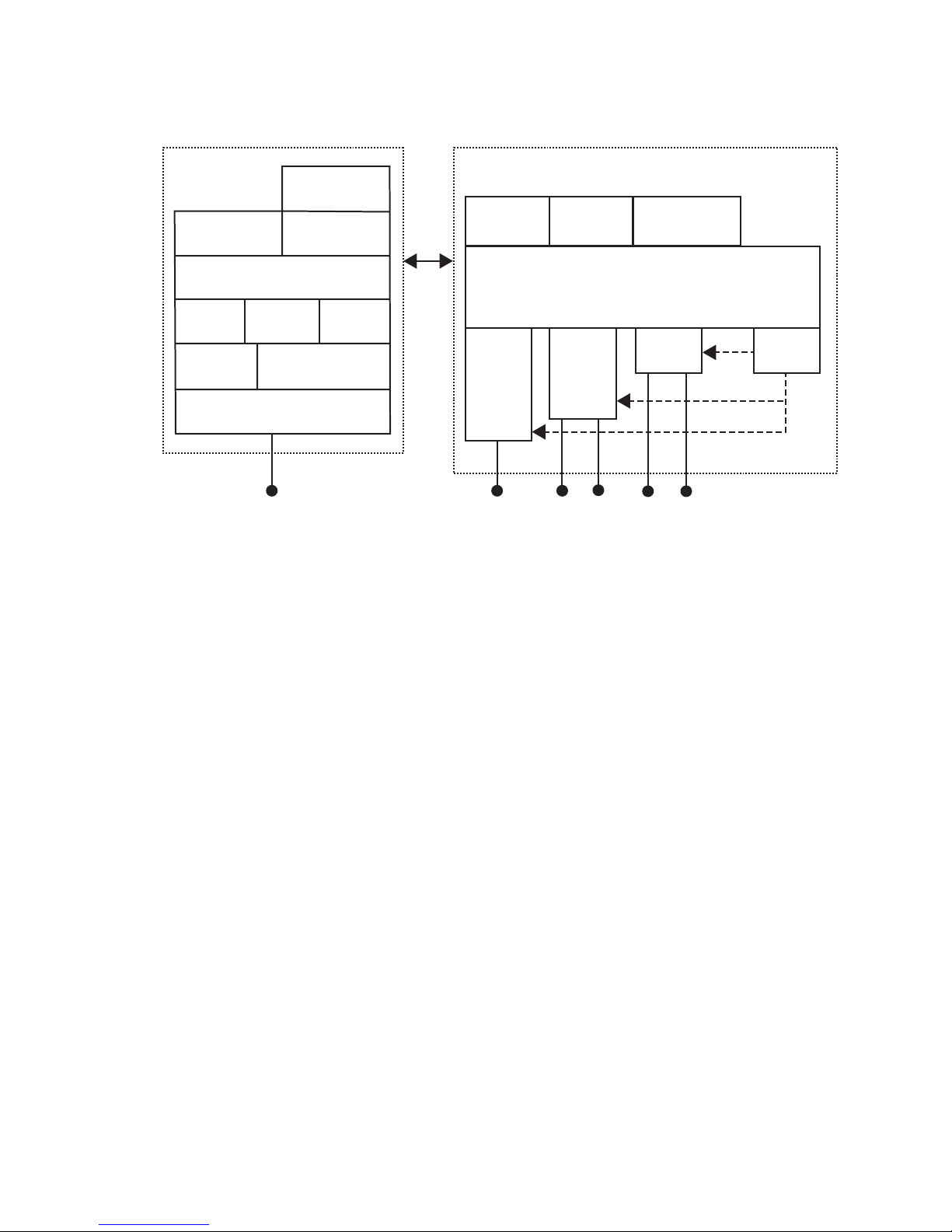
On the left, this illustration shows the ways you can manage and configure the access point, and on the right,
it shows the access point’s general multiport bridge architecture.
Access points are multiport (Ethernet-to-wireless) bridges, and because
wireless end devices operate similarly to other Ethernet devices, all your
existing Ethernet applications will work with the wireless network without
any special networking software. Any access point, except the root access
point, can concurrently receive hello messages on its Ethernet port, its
radio port, and its IP tunnel port. However, an access point can use only
one port to attach to the network. Port priorities are structured as follows:
1 Ethernet
2 IP tunnel
3 Radio
Unlike the physical Ethernet and radio ports, the IP tunnel port does not
have its own output connector. It is a logical port that provides IP
encapsulation services for frames that must be routed to reach their
destinations. Once frames are encapsulated, they are transmitted or
received through the Ethernet or radio port.
Wireless end devices may use power management to maintain battery life.
These end devices periodically wake up to receive frames that arrived while
their radio was powered down. The access point automatically provides a
pending message delivery service that holds frames until the end device is
ready to receive them.
MobileLAN access System Manual 3
Page 18

Chapter 1 — Getting Started
Features
This table lists the features of the various MobileLAN access products.
MobileLAN access Feature Comparison
Feature WA22 2101 WA21 2100 2102 2106
Access Point Yes Yes Yes Yes Yes Yes
Point-to-Point Bridge
(Wireless Bridge)
Wireless Access Point
(WAP) or Repeater
Secure Wireless Hops
(SWAP)
Secure Wireless Hops
(TLS or TTLS)
Radios 802.11b,
Dual Radio Support Yes Yes Yes Yes No No
Wi-Fi Compliant Yes Yes Yes Yes Yes Yes
802.1x Authenticator Yes Yes Yes Yes Yes Yes
802.1x Authentication
Server
Access Control List
(ACL) Server
Password Server Yes Yes Yes Yes Yes Yes
Secure Web Browser
Interface (HTTPS)
10BaseT/100BaseTx Yes Yes (2101B) Yes Yes
Fiber Optics Option Yes Yes Yes Yes No No
Serial Port Yes Yes Yes Yes Yes No
Data Link Tunneling Yes Yes Yes Yes Yes Yes
IP Tunneling Yes Yes Yes Yes Yes Yes
Antenna Diversity Yes Yes Yes Yes Yes No
Non-incentive
Antenna System
NEMA 4/IP 54
Protection
Power Supply No DC AC AC DC DC
Power Over Ethernet Yes No Yes No Yes with
Heater Option No No Yes Yes No No
Yes Yes Yes Yes Yes Yes
Yes Yes Yes Yes No Yes
Yes Yes Yes Yes Yes Yes
Yes Yes (2101B) Yes Yes
(2100D)
802.11b,
802.11a
Yes Yes (2101B) Yes Yes
Yes Yes (2101B) Yes Yes
Yes Yes (2101B) Yes Yes
Yes No Yes Yes No No
No No Yes Yes No No
OpenAir
802.11b,
802.11a
802.11b,
OpenAir,
900 MHz
(2100D)
(2100D)
(2100D)
(2100D)
No Yes
802.11b,
OpenAir
No Yes
Yes Yes
No Yes
10BaseT Yes
MobileLAN
splitter
802.11a
Yes with
MobileLAN
splitter
4 MobileLAN access System Manual
Page 19

Chapter 1 — Getting Started
Other features of all access points include:
• the ability to be managed by MobileLAN manager, a web browser,
telnet, and SNMP.
• the ability to be a DHCP server or client and a NAT server.
• the ability to be an ARP server.
• easy software distribution.
• advanced filtering of wired data traffic.
• enhanced power management for wireless end devices.
• fast roaming reliability for wireless end devices.
• load balancing.
• IEEE 802.1x security and dynamically rotating WEP keys for 802.11b
or 802.11a networks. The access point can be an authenticator and an
authentication server.
• basic WEP 64 or WEP 128 security for 802.11b or 802.11a radios.
• the ability to upgrade over the network or serial port, if the access point
has a serial port.
What’s New for Software Releases 1.90?
Software release 1.90 can be installed on all MobileLAN access products.
However, some features are only available on newer access points, which
have a faster processor and more flash memory. Newer access points are
the WA22, 2101B, WA21, 2100D, and the 2106.
Note: To determine the model of your access point, from the menu
choose Maintenance > About this Access Point. In the Config String
field, the first five characters tell you the model.
New features include these items:
• Added functionality for the 802.11a radio. Wireless hops are now fully
supported, a single radio can provide both master and station
functionality, the radio can be configured to dynamically choose the
correct frequency, statistics can be viewed.
• MobileLAN access Configuration Wizard. This wizard runs on a PC
that is on the same Ethernet segment as the access points. It discovers
the access points, helps you configure new networks, and helps you
manage previously configured networks.
• Domain Name Server (DNS) support
• Find This AP button to make locating access points easier
• Hyperlinks to make access point configuration easier and to help
identify potential configuration problems
MobileLAN access System Manual 5
Page 20
Chapter 1 — Getting Started
• IP tunnel filter that supports the AirFortress™ gateway
New security features include these items:
• (Newer access points only) Spanning tree security for 802.1x
authentication. Authentication can now be performed over wired or
wireless connections using TLS or TTLS (MSCHAPv2).
• VLAN support for each radio
• Support for the EAP-PEAP authentication method
• Configurable ACL client password
• EAP-OL key message verification, which means that the access point
verifies when a new WEP key is delivered to a wireless end device. If it is
not delivered, the key message is resent.
• Ability to configure up to six RADIUS servers
• (External RADIUS servers only) Ability to configure the port number
for the RADIUS client access point
• Additional authentication slots (up to 60) to let more wireless end
devices authenticate simultaneously
• Fast roaming for Trakker Antares terminals always enabled
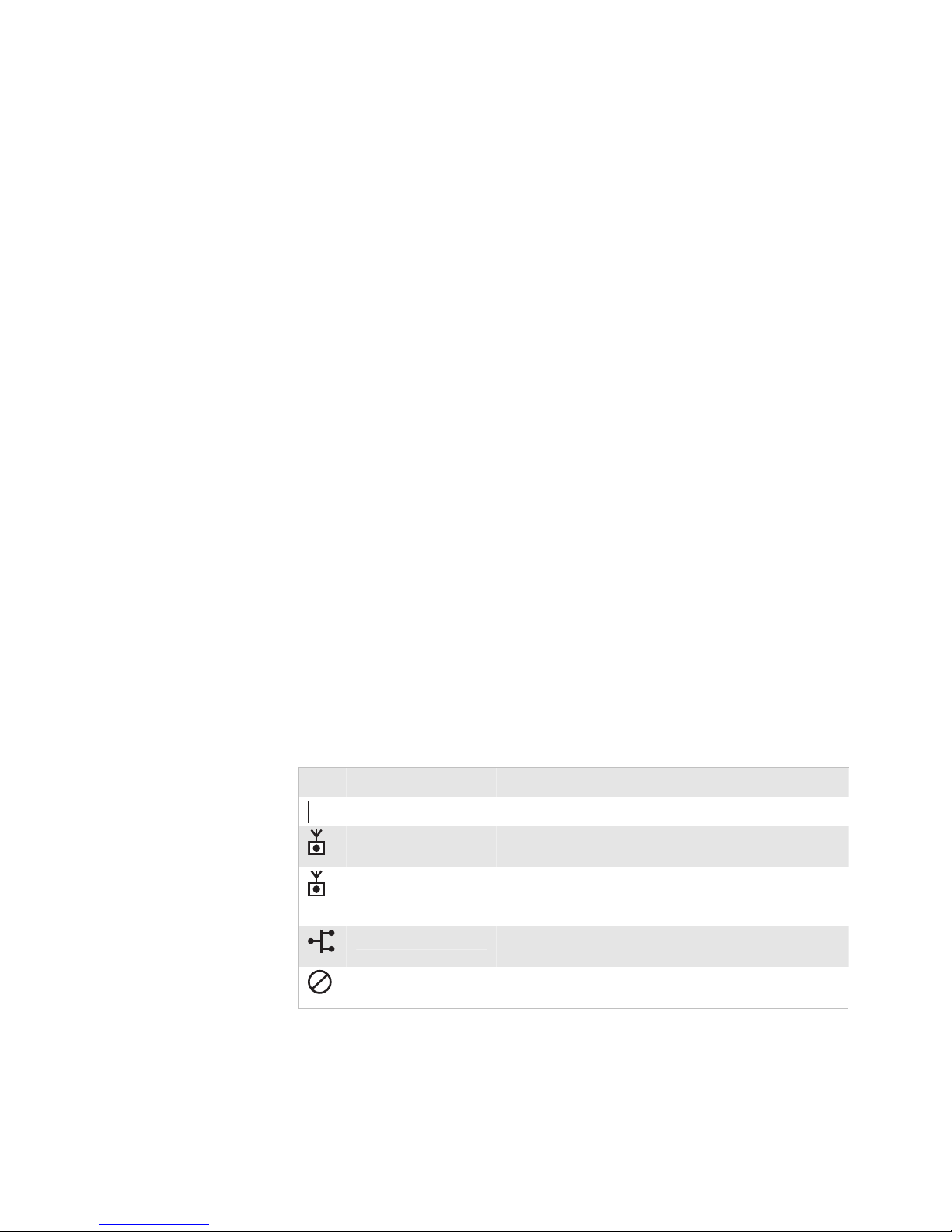
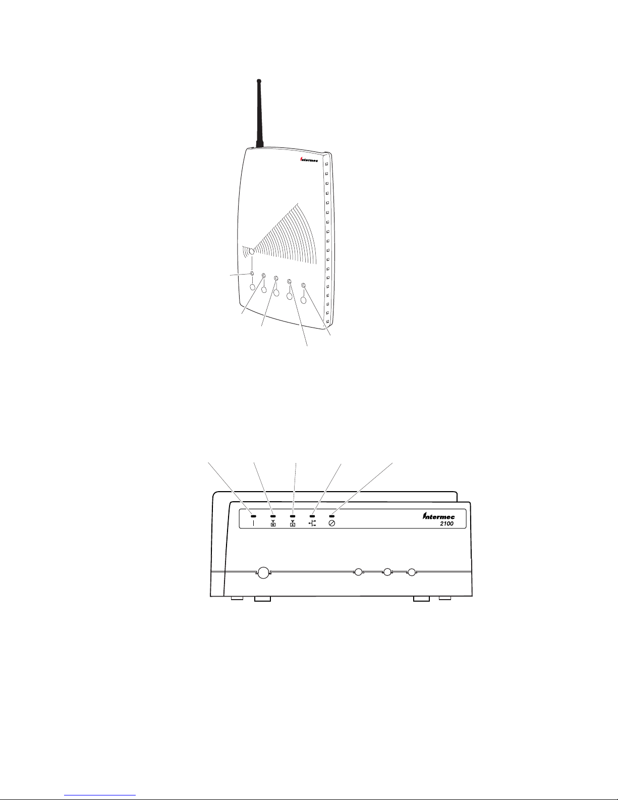
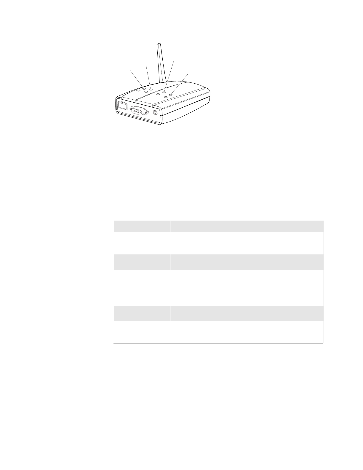
Understanding the LEDs
The 2102 and 2106 have four LEDs; the WA22, 2101, WA21, and 2100
have five LEDs. The WA22, 2101, WA21, and 2100 have a separate LED
for each of the radios. To use the LEDs to help troubleshoot the radios, see
“Troubleshooting the Radios” in Chapter 8. To understand the LEDs
during normal use, see the next table.
LED Descriptions
Icon LED Description
Power Remains on when power is applied.
Wireless #1 or Radio Flashes when a frame is transmitted or received on the
Wireless #2 (WA22,
2101, WA21, 2100,)
Wired LAN Flashes when a frame is transmitted or received on the
Root/error Flashes if this device is configured as the root. May also
radio port for the radio installed in radio slot 1.
Flashes when a frame is transmitted or received on the
radio port for the radio installed in radio slot 2 (if a
second radio is installed).
Ethernet port.
remain on if an error is detected.
6 MobileLAN access System Manual
Page 21
Chapter 1 — Getting Started
Universal Access Point
™
Power
Wireless #1
Wireless #2
Root/error
Wired LAN
21XXT018.eps
WA22 and 2101 LEDs: This illustration shows the LEDs that are on the WA22 and the
2101. For help understanding these LEDs, see the LED Descriptions table on page 6.
Powe r
Wireless#1Wireless
#2
Wired LAN
Root/
error
WA21 and 2100 LEDs: This illustration shows the LEDs that are on the WA21 and the
2100. For help understanding these LEDs, see the LED Descriptions table on page 6.
MobileLAN access System Manual 7
21XXT003.eps
Page 22
Chapter 1 — Getting Started
Power
Radio
Wired
LAN
Root/error
2102 and 2106 LEDs: This illustration shows the LEDs that are on the 2102 and the
2106. For help understanding these LEDs, see the LED Descriptions table on page 6.
Understanding the Ports
The WA22, 2101, 2102, and 2106 ports are located on the bottom of the
access point. For more information on connecting the ports, see
Chapter 2, “Installing the Access Points.”
Port Descriptions
Port Description
Power
(Not WA22,
optional WA21)
Serial
(Not 2106)
10BaseT/100BaseTx
(WA22, 2101B,
WA21, 2100D, 2106
only)
10BaseT
(2102 only)
Fiber optic
(WA22, 2101,
WA21, 2100 only)
To access the ports on the WA21 and the 2100, you must remove the
cable access door.
21XXT031.eps
Used with an appropriate power cable, this port connects the
access point to an AC power source.
Used with an RS-232 null-modem cable, this port connects the
access point to a terminal or PC to perform configuration.
Used with an appropriate cable, this port connects the access
point to your Ethernet network. The access point autonegotiates with the device it is communicating with so that the
data rate is set at the highest rate at which both devices can
communicate.
Used with an appropriate cable, this port connects the access
point to your Ethernet network.
Optional 100BaseFX port. You must use an MT-RJ connector.
Used with an appropriate cable, this port connects the access
point to your fiber optic network.
To remove the WA21 or 2100 cable access door
1 Unscrew the two thumbscrews on the cable access door.
2 Remove the door.
8 MobileLAN access System Manual
Page 23
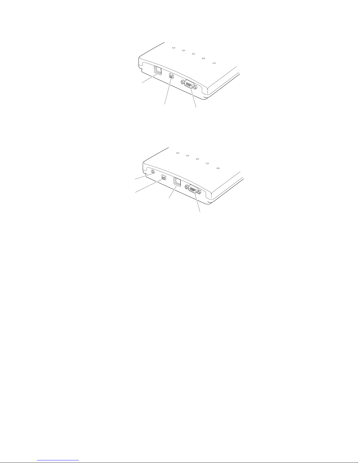
Chapter 1 — Getting Started
10BaseT/100BaseTx
Ethernet port
Fiber optic
port (optional)
Serial port
21XXT077.eps
WA22 ports: This illustration shows the ports that are on the WA22. For help
understanding these ports, see the Port Descriptions table on page 8.
Power port
Fiber optic
port (optional)
10BaseT/100BaseTx
Ethernet port
Serial port
21XXT036.eps
2101 ports: This illustration shows the ports that are on the 2101. For help
understanding these ports, see the Port Descriptions table on page 8.
MobileLAN access System Manual 9
Page 24
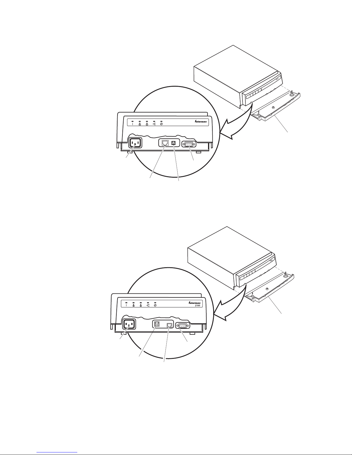
Chapter 1 — Getting Started
Cable
access
door
Power por t
(optional)
10BaseT/
100BaseTx
Ethernet port
Serial
port
Fiber optic
port (optional)
21XXT071.eps
WA21 ports: This illustration shows the ports that are on the WA21. For help
understanding these ports, see the Port Descriptions table on page 8.
Cable
access
door
Power
port
Fiber optic
port (optional)
2100 ports: This illustration shows the ports that are on the 2100. For help
understanding these ports, see the Port Descriptions table on page 8.
10 MobileLAN access System Manual
10BaseT/
100BaseTx
Ethernet port
Serial
port
21XXT002.eps
Page 25
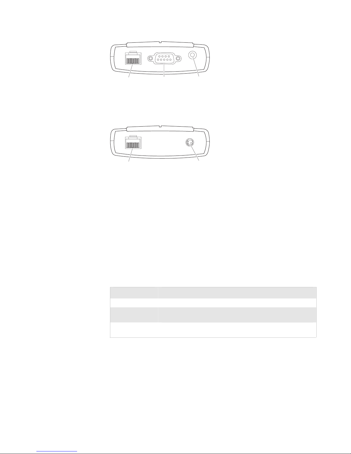
Chapter 1 — Getting Started
10BaseT
Ethernet port
2102 ports: This illustration shows the ports that are on the 2102. For help
understanding these ports, see the Port Descriptions table on page 8.
10BaseT/100BaseTx
Ethernet port
2106 ports: This illustration shows the ports that are on the 2106. For help
understanding these ports, see the Port Descriptions table on page 8.
Serial
port
Power
port
21XXT030.eps
Power
port
21XXT035.eps
How the Access Point Fits in Your Network
In general, the access point forwards data from wireless end devices to the
wired Ethernet network. You can also use the access point as a point-topoint bridge, or if your access point has two radios, you can use it as a
point-to-multipoint bridge or a WAP. Use the access point in the
following locations and environments.
Which Access Point to Use for Your Environment
Access Point Environment
WA22 and 2101 Use in most indoor environments.
WA21 and 2100 Use in locations where an access point is exposed to extreme
environments.
2102 and 2106 Use when you have a simple wireless network, do not need mixed
radios, or want a point-to-point bridge to a secondary LAN.
The access point supports a variety of network configurations. These
configurations are explained in this section.
MobileLAN access System Manual 11
Page 26
Chapter 1 — Getting Started
ps
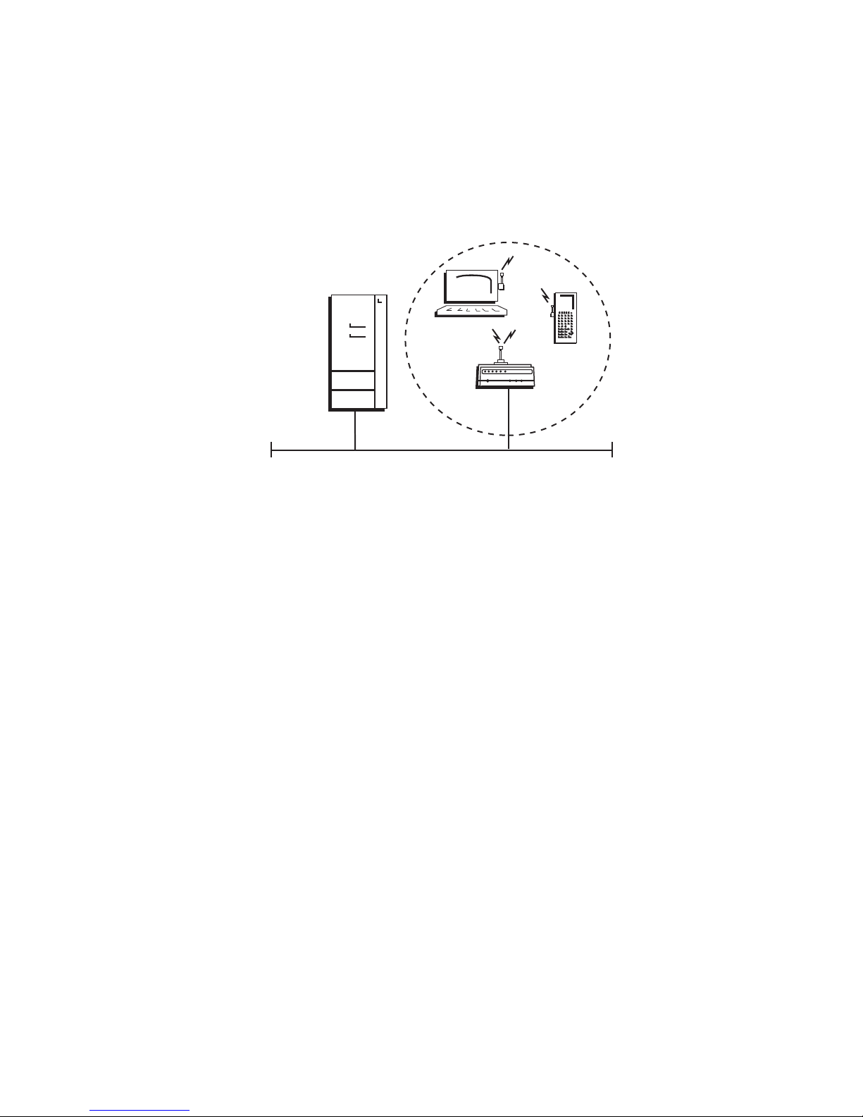
Using One Access Point in a Simple Wireless Network
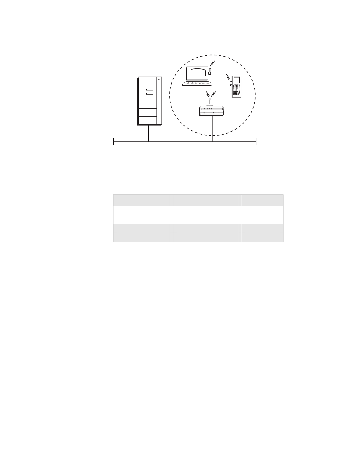
You can use an access point to extend your existing Ethernet network to
include wireless end devices. The access point connects directly to your
wired network and the end devices provide a wireless extension of the
wired LAN.
Host
Ethernet
Access
point
This illustration shows a simple wireless network with one access point and some
wireless end devices.
21XXT004.e
In a simple wireless network, the access point that is connected to the
wired network serves as a transparent bridge between the wired network
and wireless end devices.
To install a simple wireless network
1 Configure the initial IP address. For help, see “Configuring the Access
Point” on page 29.
2 Install the access point. For help, see Chapter 2, “Installing the Access
Points.”
3 Configure the Ethernet network. For help, see Chapter 3, “Configuring
the Ethernet Network.”
4 Configure the radios. For help, see Chapter 4, “Configuring the
Radios.”
5 Decide what level of security you want to implement in your network.
For help, see Chapter 6, “Configuring Security.”
12 MobileLAN access System Manual
Page 27
Chapter 1 — Getting Started
ps
Example - Configuring an 802.11b Access Point
Host
Access
point
Ethernet
In this example, there is one 802.11b radio in the access point. Wireless end devices use
the access point to communicate with the host and other end devices.
21XXT004.e
Configuring an 802.11b Access Point Parameters
Screen Parameter Access Point
IEEE 802.11b Radio Node Type Master
SSID (Network Name) Manufacturing
Spanning Tree Settings Root Priority 5
Ethernet Bridging Enabled Checked
Intermec recommends that you always implement some type of security.
Using Multiple Access Points and Roaming Wireless End Devices
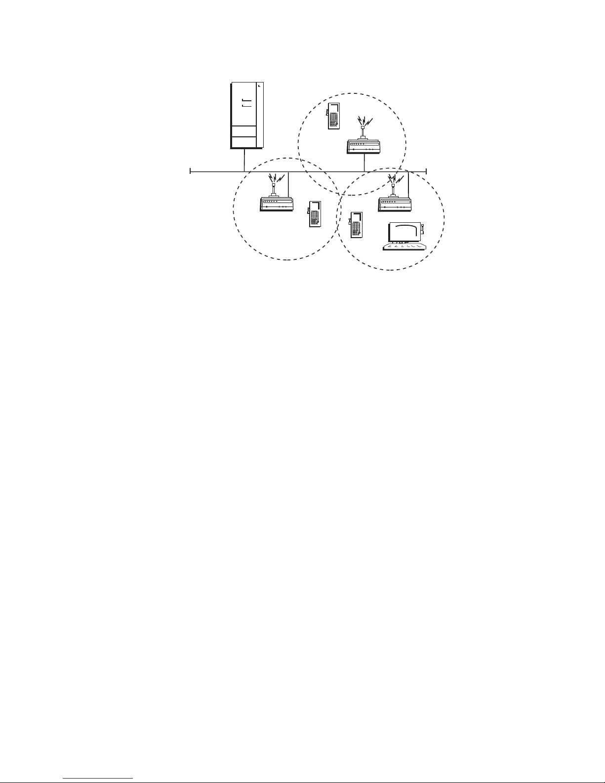
For larger or more complex environments, you can install multiple access
points so wireless end devices can roam from one access point to another.
Multiple access points establish coverage areas or cells similar to those of a
cellular telephone network. End devices can connect with any access point
that is within range and belongs to the same wireless network.
MobileLAN access System Manual 13
Page 28
Chapter 1 — Getting Started
s
Host
Ethernet
UAPUAP
UAP
This illustration shows a wireless network with multiple access points. Wireless end
devices can roam between the access points to communicate with the host and other
end devices.
21XXT006.ep
An end device initiates a roam when it attaches to a new access point. The
access point sends an attach message to the root access point, which in turn
forwards a detach message to the previous access point, allowing each
access point to update its forwarding database. Intermediate access points
monitor these exchanges and update their forwarding databases.
With the access point’s multichannel architecture, you can have more than
one access point within the same cell area to increase throughput and
provide redundancy. For more information, see “Using Dual Radio Access
Points for Redundancy” on page 28.
To install multiple access points with roaming end devices
1 Follow the instructions for installing a simple wireless network on page
12.
2 Configure the LAN ID. For help, see “Configuring the Spanning Tree
Parameters” in Chapter 5.
3 Configure one of the access points to be a root access point. For help,
see “About the Primary LAN and the Root Access Point” in Chapter 5.
4 If your network has a switch that is not IEEE 802.1d-compliant and is
located between access points, configure data link tunneling. For help,
see “About Data Link Tunneling” in Chapter 5.
14 MobileLAN access System Manual
Page 29
Chapter 1 — Getting Started
Example - Configuring an OpenAir Access Point with Roaming End
Devices
Host
AP2
Ethernet
AP3
AP1
UAP
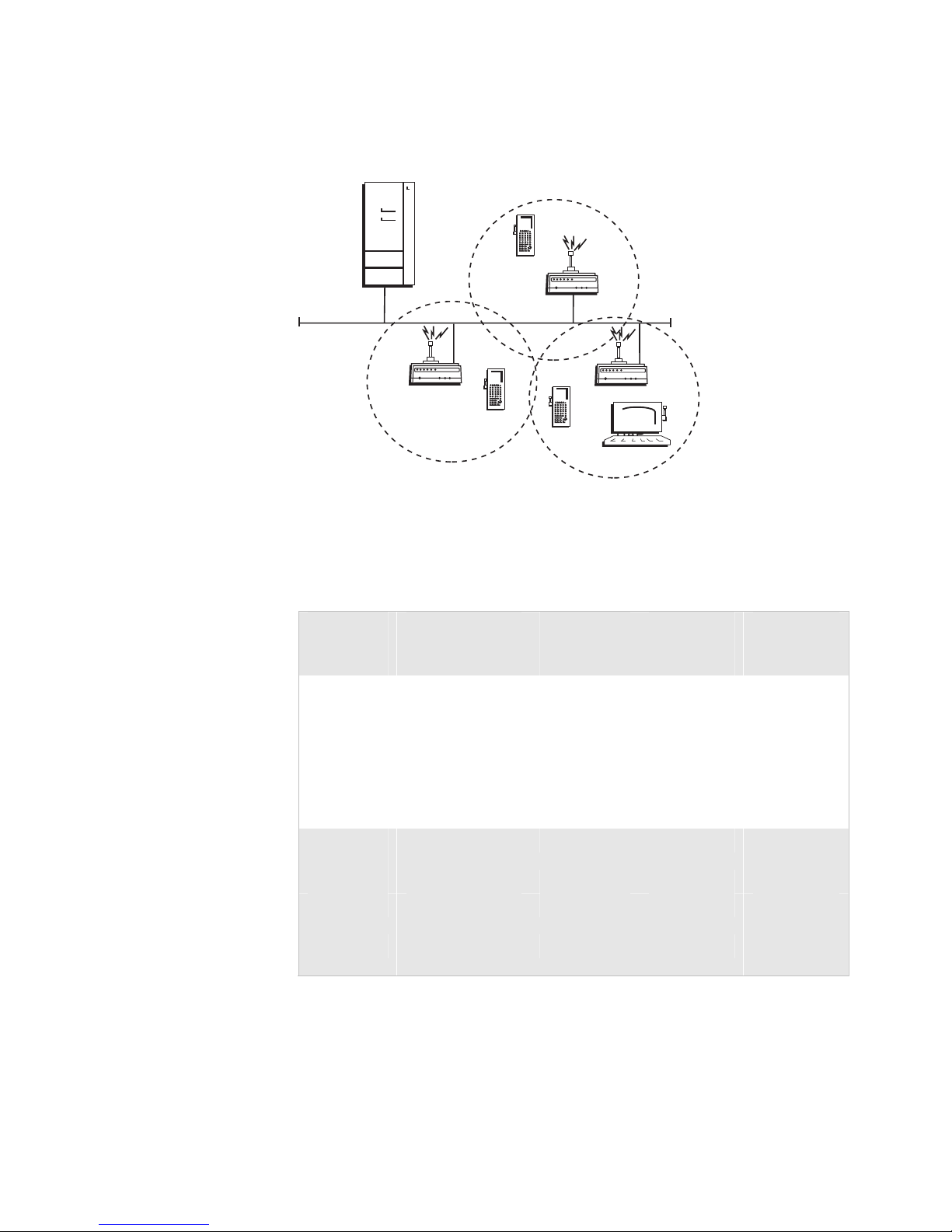
In this example, there is one OpenAir radio in each access point. Wireless end devices
can roam between the access points to communicate with the host and other end
devices.
21XXT007.eps
Configuring OpenAir Access Points Parameters
Screen
OpenAir
Radio
Security ID Op3rat!ons Op3rat!ons Op3rat!ons
Channel 1 2 3
Subchannel 1 1 1
MAC
Spanning
Tree Settings
Root Priority 5 4 3
Ethernet Bridging
Secondary LAN
Parameter
Node Type Master Master Master
Configuration
LAN ID 0 0 0
Enabled
Bridge Priority
AP1
OpenAir
Radio (Root)
Default Default Default
Checked Checked Checked
0 0 0
AP2
OpenAir
Radio
AP3
OpenAir
Radio
You should configure different channel/subchannel combinations for each
access point. The access points communicate with each other through the
spanning tree. The wireless end devices are configured as stations with
LAN ID set to 0 and Security ID set to Op3rat!ons.
MobileLAN access System Manual 15
Page 30
Chapter 1 — Getting Started
Using an Access Point as a WAP
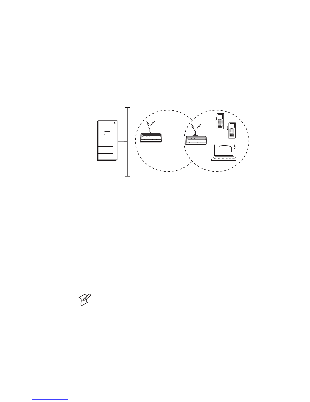
You can extend the range of your wireless network by configuring a dual
radio access point as a wireless access point (WAP). The WAP and the
wireless end devices it communicates with comprise a secondary LAN. You
can position WAPs in strategic locations so they receive data from end
devices, and then forward the data to the wired network. This
configuration can be useful when distance or physical layout impedes radio
reception and transmission.
Host
Access
point
Ethernet
This illustration shows a simple wireless network with one access point and one WAP.
Wireless end devices use the WAP to forward data to the access point.
WAP
21XXT011.eps
WAPs send data from end devices to the access points via wireless hops.
Wireless hops are formed when data from end devices move from one
access point to another access point through the radio ports. The master
radio in the access point transmits hello messages, which allow the WAPs
to attach to the spanning tree in the same way as access points.
If you have an 802.11b or an OpenAir network, the WAP must contain
two radios. The WAP master radio must match the end devices radios and
the WAP station radio must match the master radio in the access point.
If you have an 802.11a or 902 MHz network, the WAP only needs one
radio because this radio can simultaneously be a master and a station. This
radio will create wireless hops automatically when it cannot communicate
to the wired network.
Note: The 2102 cannot be WAPs because it only contains one 802.11b
radio.
WAPs must be on the same IP subnet as the access point. Also, data from
wireless end devices should not go through more than three wireless hops
before it gets to an access point on the primary LAN.
16 MobileLAN access System Manual
Page 31
Chapter 1 — Getting Started
The following procedure explains how to install a simple wireless network
with a WAP and no roaming end devices. For help installing a simple
wireless network with a WAP and roaming end devices, see the two
examples in the next sections.
To install a simple wireless network with a WAP and no roaming end devices
1 Follow the instructions for installing a simple wireless network on page
12.
2 Configure the LAN ID. For help, see “Configuring the Spanning Tree
Parameters” in Chapter 5.
3 (802.11b, OpenAir) Configure the station radio in the WAP.
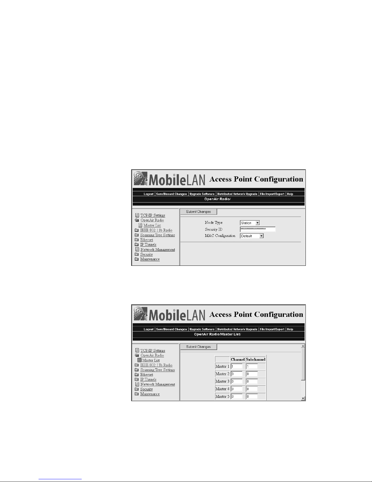
a From the main menu, click the link corresponding to the station
radio. The radio screen appears.
b In the Node Type field choose Station, and then click Submit
Changes.
c (OpenAir) Click Master List. The Master List screen appears.
In the Channel field and Subchannel field, enter the channel and
subchannel of all master radios with which this station can
communicate.
MobileLAN access System Manual 17
Page 32

Chapter 1 — Getting Started
4 Click Submit Changes to save your changes. To activate your changes,
from the menu bar click Save/Discard Changes, and then click Save
Changes and Reboot. For help, see “Saving Configuration Changes”
on page 36.
5 Configure the master radio (in the WAP) to communicate with the end
devices. For help, see Chapter 4, “Configuring the Radios.”
6 Configure the master radio in the access point.
a From the main menu, click the link corresponding to the master
radio. The radio screen appears.
b In the Node Type field, choose Master and then click Submit
Changes.
7 Configure the access point to be a root access point. For help, see
“About the Primary LAN and the Root Access Point” in Chapter 5.
8 Click Submit Changes to save your changes. To activate your changes,
from the menu bar click Save/Discard Changes, and then click Save
Changes and Reboot. For help, see “Saving Configuration Changes”
on page 36.
18 MobileLAN access System Manual
Page 33
Chapter 1 — Getting Started
Example - Configuring an 802.11b WAP With Roaming End Devices
Host
Access
point
Ethernet
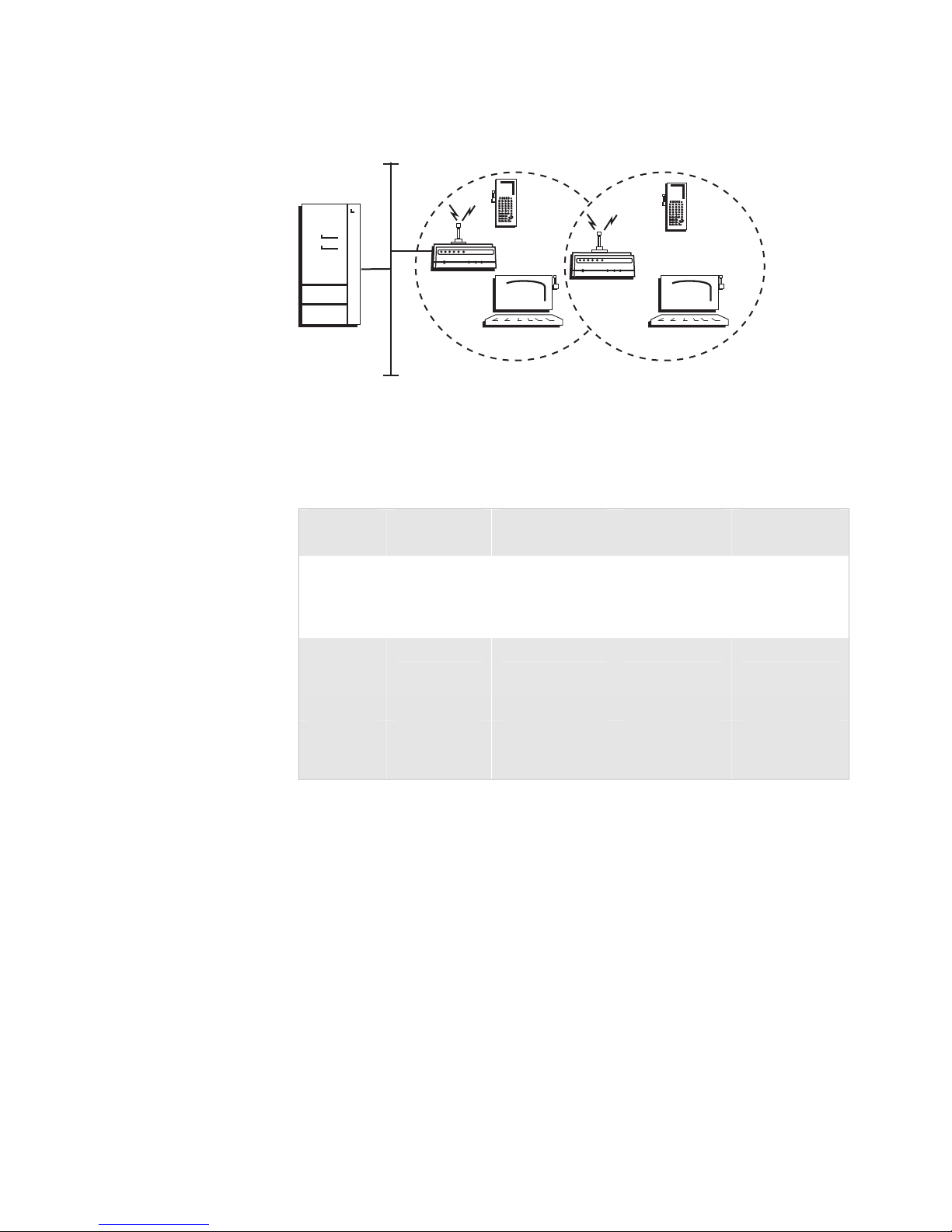
In this example, there is one 802.11b radio in the access point and there are two 802.11b
radios (IEEE 802.11b-1 and IEEE 802.11b-2) in the WAP. Wireless end devices can roam
between the WAP and the access point.
WAP
21XXT012.eps
Configuring an 802.11b Access Point and WAP Parameters
Screen
IEEE
802.11b
Radio
SSID Manufacturing Manufacturing Manufacturing
Spanning
Tree
Settings
Root Priority 5 0 N/A
Ethernet
Parameter
Node Type Master Master Station
LAN ID 11 11 11
Bridging
Enabled
Access Point
IEEE 802.11b
Checked Checked N/A
WAP IEEE
802.11b-1
WAP IEEE
802.11b-2
You need to configure the wireless end devices to have the same SSID,
LAN ID, and frequency as the WAP master radio (IEEE 802.11b-1). You
do not need to configure any secondary LAN settings because the WAP is
not connected to a secondary LAN.
Intermec recommends that you always implement some type of security.
MobileLAN access System Manual 19
Page 34
Chapter 1 — Getting Started
Example - Configuring an 802.11a WAP With Roaming End Devices
Host
Access
point
Ethernet
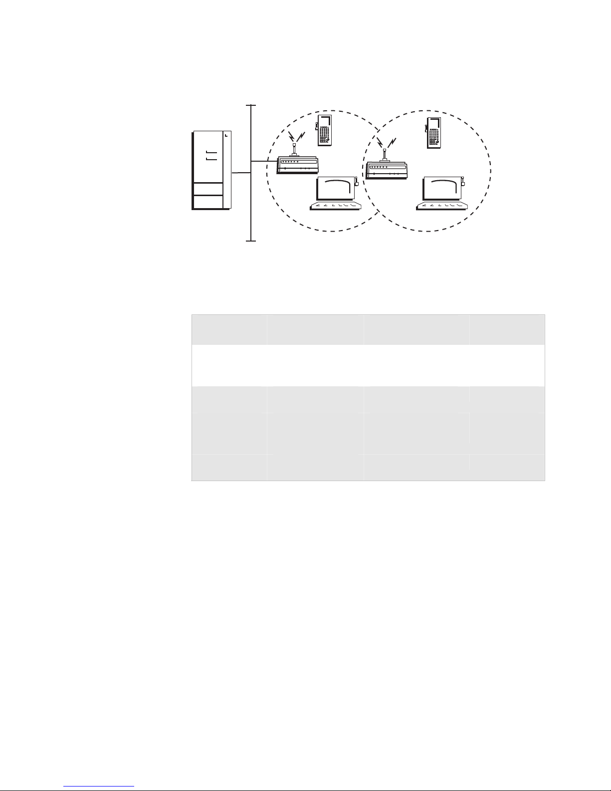
In this example, there is one 802.11a radio in the access point and there is one 802.11a
radio in the WAP. Wireless end devices can roam between the WAP and the access point.
WAP
21XXT012.eps
Configuring an 802.11a Access Point and WAP Parameters
Screen
IEEE 802.11a
Radio
SSID Manufacturing Manufacturing
Spanning Tree
Settings
Root Priority 5 0
Ethernet Bridging
Secondary LAN
Parameter
Node Type Master Master
LAN ID 11 11
Enabled
Bridge Priority
Access Point IEEE
802.11a
Checked Checked
0 0
WAP IEEE
802.11a
You need to configure the wireless end devices to have the same SSID,
LAN ID, and frequency as the WAP radio. You do not need to configure
any secondary LAN settings because the WAP is not connected to a
secondary LAN.
Intermec recommends that you always implement some type of security.
20 MobileLAN access System Manual
Page 35
Chapter 1 — Getting Started
Example - Configuring an OpenAir WAP With Roaming End Devices
Host
Access
point
Ethernet
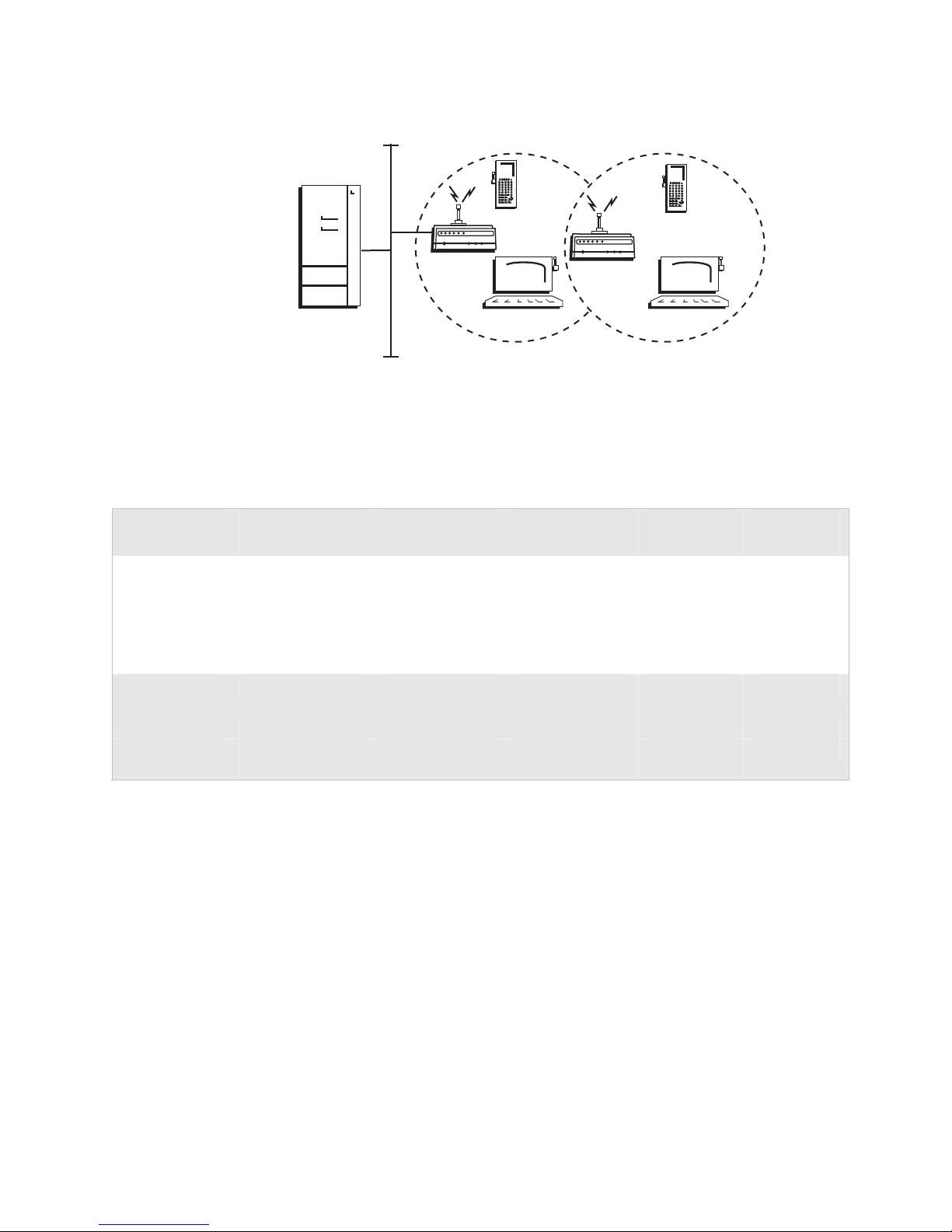
In this example, there are two OpenAir radios in the access point and there are two
OpenAir radios in the WAP. To provide better throughput, one master radio in the access
point is configured to allow wireless end devices to communicate with it and the other
master radio is configured to communicate only with the WAP station radio.
WAP
21XXT012.eps
Configuring an OpenAir Access Point and WAP Parameters
Screen
OpenAir Radio Node Type Master Master Master Station
Security ID Area2 Area1 Area2 Area1
Channel 2 1 2 N/A
Subchannel 1 1 1 N/A
MAC Configuration Default Default Default Default
Spanning Tree
Settings
Root Priority 5 0 0 0
Ethernet Bridging
Parameter
LAN ID 0 0 0 0
Enabled
Access Point
OpenAir-1
Checked Checked Checked Checked
Access Point
OpenAir-2
WAP
OpenAir-1
WAP
OpenAir-2
You also need to add the channel (1) and the subchannel (1) of the master
radio that the WAP station radio is communicating with (Access Point
OpenAir-2) to the Master List for the WAP station radio. You do not need
to configure any secondary LAN settings because the WAP is not
connected to a secondary LAN.
You need to configure the wireless end devices to have the same LAN ID
and security ID as the WAP master radio (WAP OpenAir-1).
MobileLAN access System Manual 21
Page 36
Chapter 1 — Getting Started
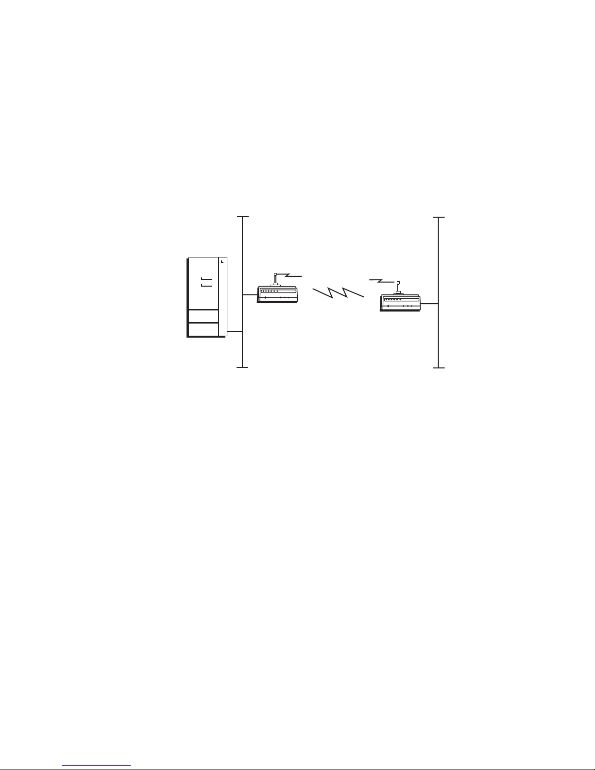
Using Access Points to Create a Point-to-Point Bridge
You can use access points to create a point-to-point bridge between two
wired LANs. That is, you can have one access point wired to a primary
LAN in one building and have a second access point wired to a secondary
LAN in another building. This configuration lets wired and wireless end
devices in both buildings communicate with each other, which can be
useful in a campus environment or any other environment where
pavement or other objects prevent installation of a wired link.
Primary LAN Secondary LAN
Host
Root
This illustration shows two simple wireless networks that are connected with access
points that are acting as point-to-point bridges.
Designated
bridge
21XXT013.eps
Point-to-point bridges send data from end devices on the secondary LAN
to the root access point via wireless hops. Wireless hops are formed when
data from end devices move from one access point to another access point
through the radio ports. The master radio in the point-to-point bridge on
the primary LAN transmits hello messages, which allow the bridge on the
secondary LAN to attach to the spanning tree in the same way as access
points.
If the access points are simply acting as a point-to-point bridge or if you
have an 802.11a or 902 MHz network, each access point only needs one
radio. If you have an 802.11b or an OpenAir network and you want the
designated bridge to also be able to communicate with wireless end devices
(point-to-multipoint), the designated bridge must be a dual radio access
point. The designated bridge master radio must match the end device
radios and the station radio must match the root master radio.
Data from wireless end devices should not go through more than three
wireless hops before it gets to an access point on the primary LAN.
22 MobileLAN access System Manual
Page 37

Chapter 1 — Getting Started
You need to set the root priorities and secondary LAN bridge priorities for
the bridge on the primary LAN and for the bridge on the secondary LAN:
• On the primary LAN bridge, set the root priority to a number that is
greater than the root priority of the secondary LAN bridge. The access
points will not form a point-to-point bridge if the primary LAN bridge
has a lower root priority than the secondary LAN bridge.
• On the secondary LAN bridge, set root priority to 0 and the secondary
LAN bridge priority to a number other than 0.
You may also need to adjust the flooding parameters. Here are some
recommendations:
• If there are no end devices on the secondary LAN, the bridge on the
secondary LAN can use the default flooding settings. The Secondary
LAN Flooding parameter is disabled.
• If there are end devices on the secondary LAN, the bridge on the
secondary LAN should have Secondary LAN Flooding parameter set to
Multicast. If you also want unicast flooding, you can set this parameter
to Enabled.
• If there are end devices on the secondary LAN and the end devices
communicate with end devices on another secondary LAN, the root
access point should have its Multicast Flooding parameter set to
Universal. This setting ensures that all ARP requests and multicast
traffic is distributed through a second or third hop.
To install a point-to-point or a point-to-multipoint bridge
1 Follow the instructions for installing a simple wireless network on page
12.
2 Configure the LAN ID. For help, see “Configuring the Spanning Tree
Parameters” in Chapter 5.
3 (802.11b, OpenAir) Configure the station radio in the point-to-point
bridge on the secondary LAN.
a From the main menu, click the link corresponding to the station
radio. The radio screen appears.
MobileLAN access System Manual 23
Page 38
Chapter 1 — Getting Started
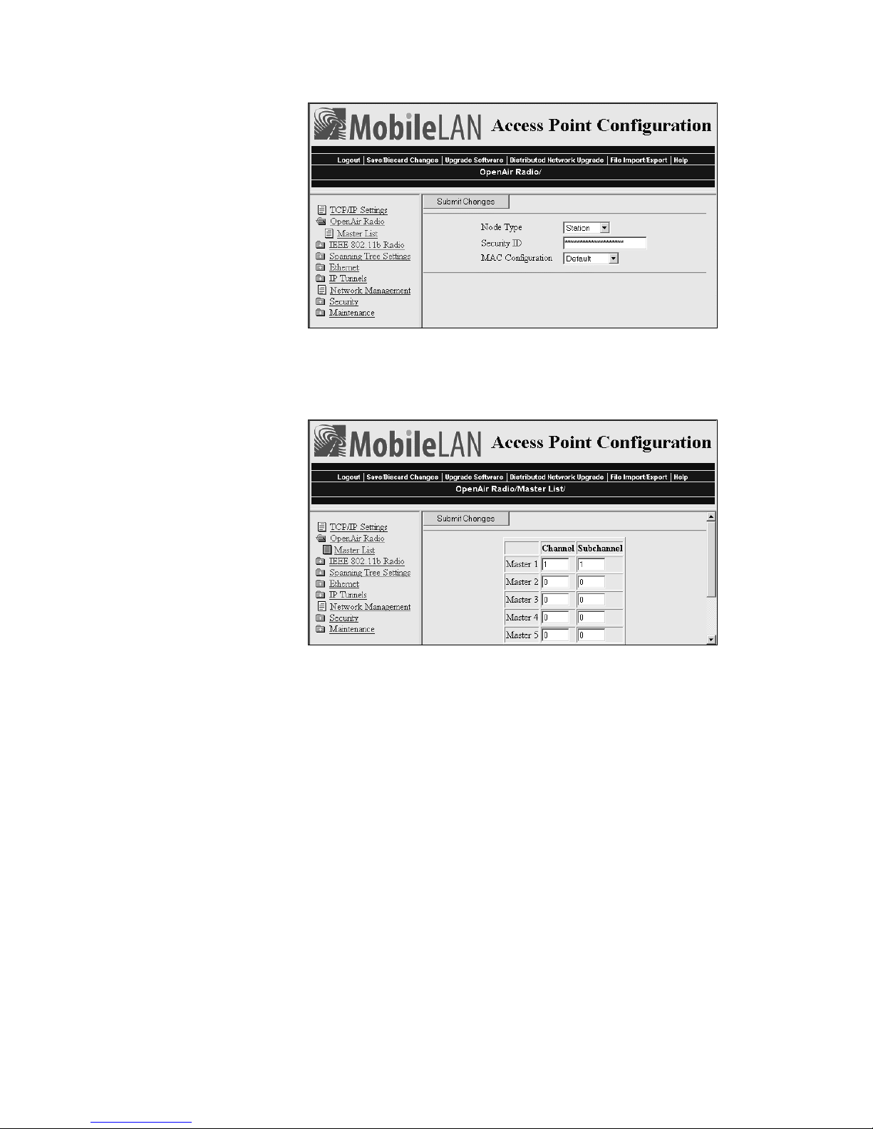
b In the Node Type field choose Station, and then click Submit
Changes.
c (OpenAir) Click Master List. The Master List screen appears.
In the Channel field and Subchannel field, enter the channel and
subchannel of all master radios with which this station can
communicate.
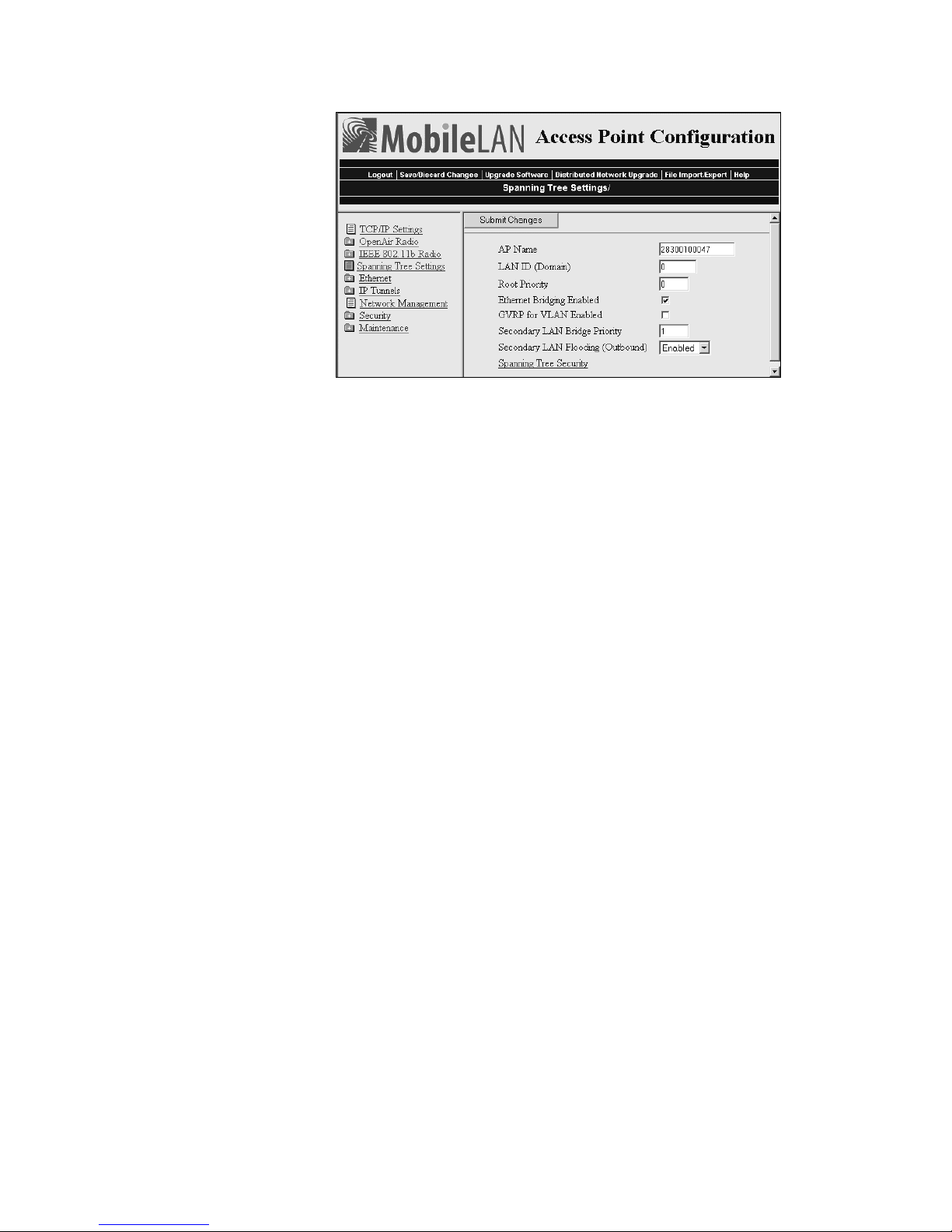
4 Configure the spanning tree settings for the point-to-point bridge on
the secondary LAN.
a From the main menu, click Spanning Tree Settings. The Spanning
24 MobileLAN access System Manual
Tree Settings screen appears.
Page 39
Chapter 1 — Getting Started
b In the Root Priority field, enter 0.
c In the Secondary LAN Bridge Priority field, enter a number other
than zero.
d In the Secondary LAN Flooding field choose Enabled.
5 Click Submit Changes to save your changes. To activate your changes,
from the menu bar click Save/Discard Changes, and then click Save
Changes and Reboot. For help, see “Saving Configuration Changes”
on page 36.
6 Configure the master radio in the point-to-point bridge on the primary
LAN.
a From the main menu, click the link corresponding to the master
radio. The radio screen appears.
b In the Node Type field choose Master, and then click Submit
Changes.
7 Configure the spanning tree settings for the point-to-point bridge on
the primary LAN.
a From the main menu, click Spanning Tree Settings. The Spanning
Tree Settings screen appears.
b In the Root Priority field, enter a number other than 0.
c In the Secondary LAN Bridge Priority field, enter 0.
d In the Secondary LAN Flooding field choose Disabled.
8 If the roaming end devices will be roaming across an IP router, you
must configure IP tunnels. For help, see “Configuring IP Tunnels” in
Chapter 5.
9 Click Submit Changes to save your changes. To activate your changes,
from the menu bar click Save/Discard Changes, and then click Save
Changes and Reboot. For help, see “Saving Configuration Changes”
on page 36.
MobileLAN access System Manual 25
Page 40
Chapter 1 — Getting Started
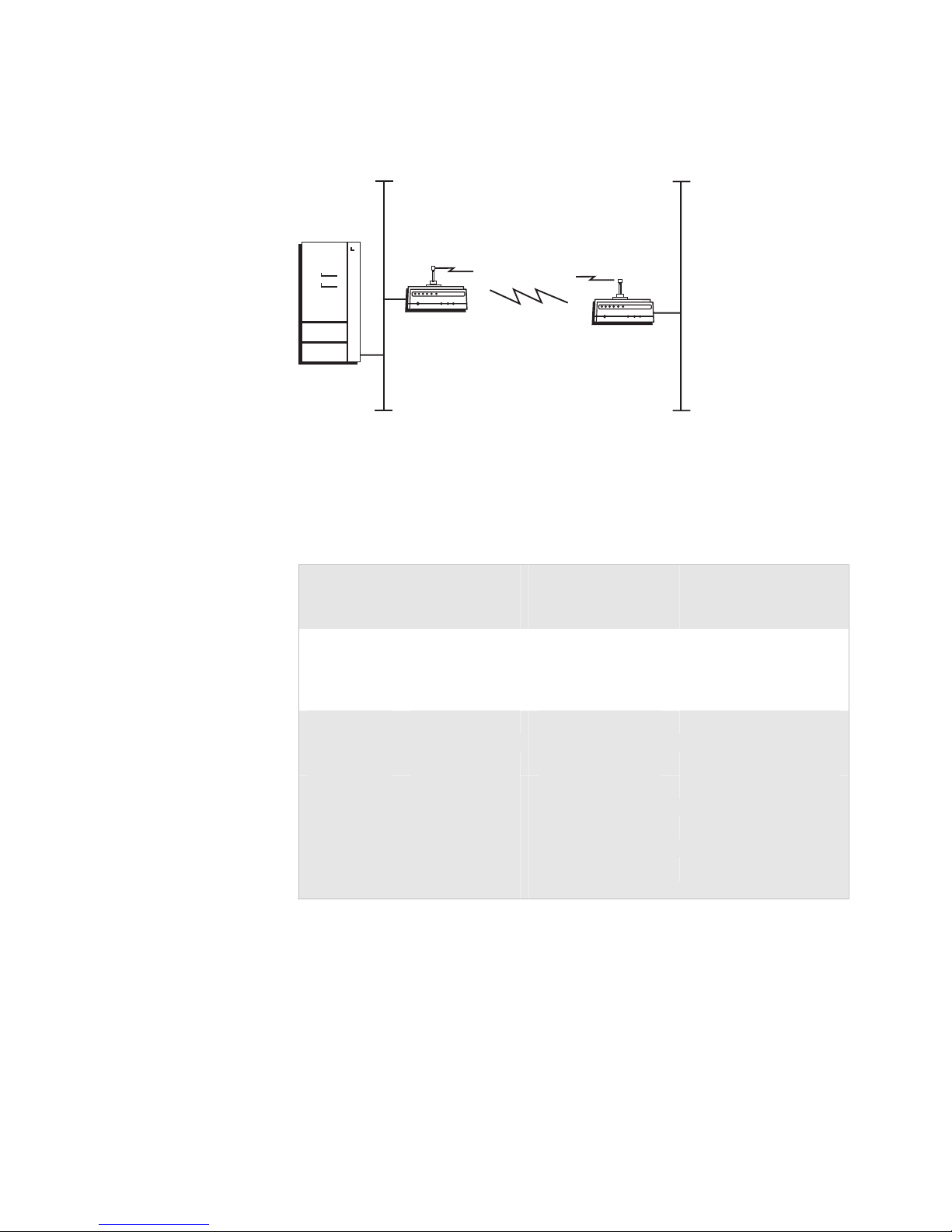
Example - Configuring an 802.11b Bridge
Primary LAN Secondary LAN
Host
Root
Designated
bridge
21XXT013.eps
In this example, each access point only has one 802.11b radio. Since the designated
bridge only has a station radio, wireless end devices can only communicate with the
root access point. However, wired devices on the secondary LAN can communicate with
the primary LAN.
Configuring 802.11b Point-to-Point Bridges Parameters
Screen
IEEE
802.11b
Radio
SSID Manufacturing Manufacturing
Spanning
Tree Settings
Root Priority 5 0
Ethernet Bridging
Secondary LAN
Secondary LAN
Parameter
Bridge - Primary
LAN (Root)
Bridge – Secondary
LAN (Designated
Bridge)
Node Type Master Station
LAN ID 0 0
Checked Checked
Enabled
0 1
Bridge Priority
Disabled Enabled
Flooding
Intermec recommends that you always implement some type of security.
26 MobileLAN access System Manual
Page 41
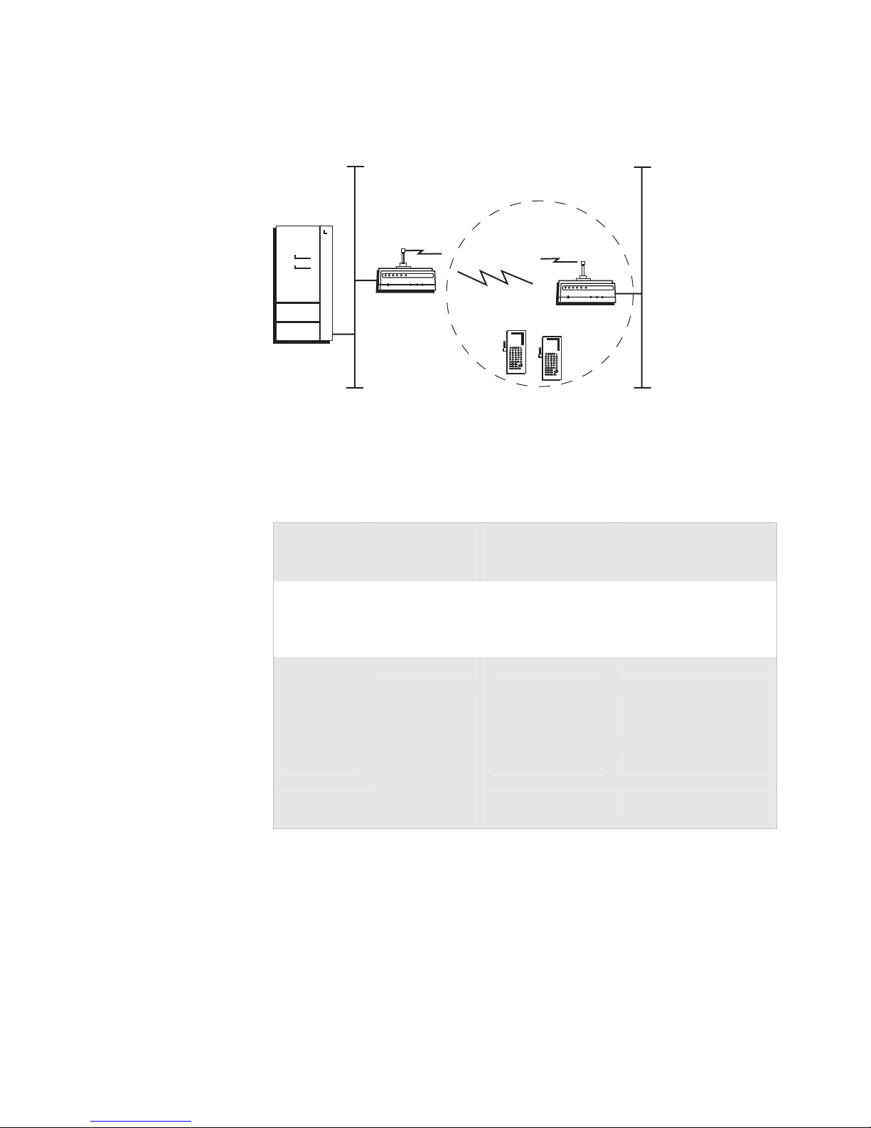
Example - Configuring an 802.11a Bridge
Primary LAN Secondary LAN
Host
Chapter 1 — Getting Started
Root
Designated
bridge
21XXT050.eps
In this example, each access point only has one 802.11a radio. Since the 802.11a radio
can function as a master and a station, wireless end devices can communicate with
either access point.
Configuring 802.11a Point-to-Point Bridges Parameters
Screen
IEEE
802.11b
Radio
SSID Manufacturing Manufacturing
Spanning
Tree Settings
Root Priority 5 0
Ethernet Bridging
Secondary LAN
Secondary LAN
Parameter
Bridge - Primary
LAN (Root)
Bridge – Secondary
LAN (Designated
Bridge)
Node Type Master Master
LAN ID 11 11
Checked Checked
Enabled
0 1
Bridge Priority
Disabled Enabled
Flooding
Intermec recommends that you always implement some type of security.
MobileLAN access System Manual 27
Page 42
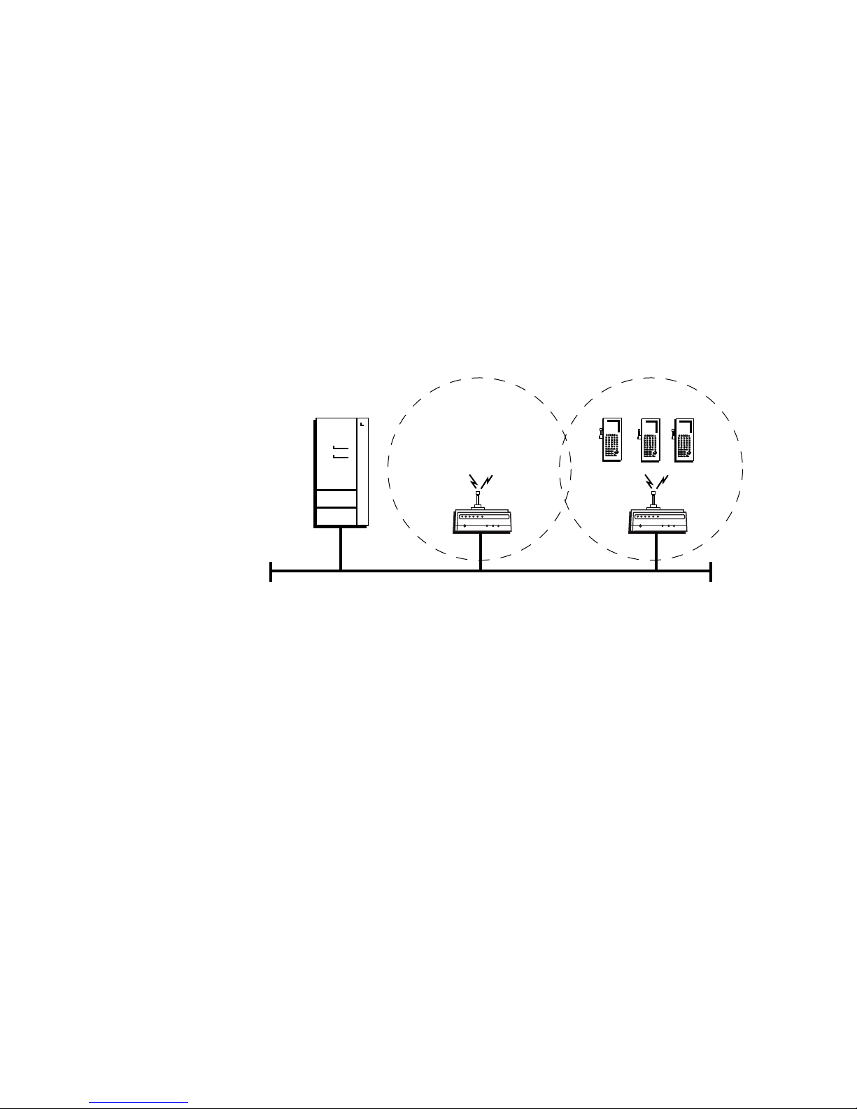
Chapter 1 — Getting Started
Using Dual Radio Access Points for Redundancy
You can configure WA22s, 2101s, WA21s, and 2100s that have two
802.11b radios, two 802.11a radios, or two OpenAir radios to provide
redundancy for your network. During normal operations, end devices send
frames to the master radio in one of the access points, which bridges the
frames to the wired network. If a section of the wired network goes down,
the master radio receives the frames, and then the station radio forwards
the frames to a master radio in another access point that is within range.
In each access point, you need to configure one radio’s node type as a
Master, which communicates with the wireless end devices and configure
the other radio’s node type as a Station, which communicates to another
access point with a master radio and within range.
Host
AP1
Ethernet
In this example, AP3 is a dual radio access point. It may be located on a loading dock or
other remote location. During normal operations, AP3 functions as a normal access
point, transmitting frames to and from the host. However, if the Ethernet connection is
disrupted, AP3 can function as a WAP and continue operations by transmitting frames
to a master radio in AP1. AP3 must be within range of AP1.
AP3
21XXT014.eps
To install dual radio access points for redundancy
• Follow the instructions for installing a simple wireless network with a
WAP on page 16.
28 MobileLAN access System Manual
Page 43

Chapter 1 — Getting Started
Configuring the Access Point (Setting the IP Address)
The access point will work out of the box if you are using a DHCP server
to assign it an IP address. By default, the access point is configured to be a
DHCP client and will respond to offers from any DHCP server. However,
if you are not using a DHCP server to assign an IP address, you can use:
• the MobileLAN access Configuration Wizard, which also configures
radio parameters and security parameters. All access points must be at
factory defaults. You install this wizard from the MobileLAN access
Tools CD that shipped with the access point. This wizard can configure
all the access points that are on the same Ethernet segment and subnet
as the PC it is installed on. For more information, run the wizard.
• the MobileLAN access Utility, but you need to know the access point
MAC address. You install this utility from the MobileLAN access Tools
CD that shipped with the access point. This utility must be installed on
a PC that is on the same Ethernet segment and subnet as (or must be
communicating wirelessly with) the access point. For help, see “Using
the MobileLAN access Utility” on page 29.
Note:, If your access points are running software release 1.90 or later,
you must use MobileLAN access Utility v2.0.
• a communications program, such as HyperTerminal, which also
configures other parameters. This program must be installed on a PC
with an open serial port. For help, see “Using a Communications
Program” on page 31.
This manual assumes that you are using the MobileLAN access Utility or a
communications program for your initial configuration, and then using a
web browser interface to perform all other configurations. You can also
continue to use a communications program or you can start a telnet
session to configure the access point.
Using the MobileLAN access Utility
The MobileLAN access Utility is an easy-to-use Microsoft® Windows™-
based utility that lets you:
• set the initial IP address for the access point. This utility eliminates the
need to serially connect a PC to the access point to configure its IP
address.
• restore the access point settings to factory defaults. For help, see the
online help and “Restoring the Access Point to the Default
Configuration” in Chapter 8.
• recover a failed access point. For help, see the online help and
“Recovering a Failed Access Point” in Chapter 8.
MobileLAN access System Manual 29
Page 44
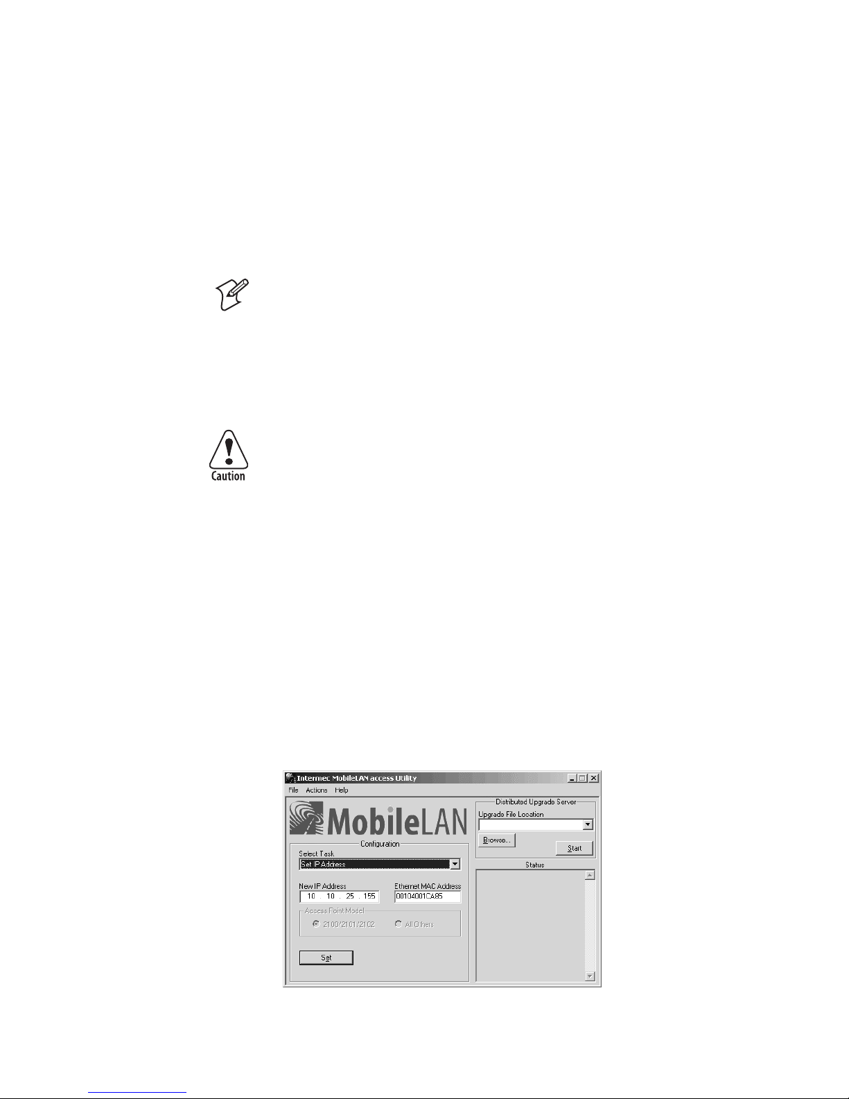
Chapter 1 — Getting Started
• upgrade the access point software. For help, see the online help and
“Upgrading the Access Points” in Chapter 8.
After you configure the IP address, you can use a web browser or a telnet
session to complete the configuration.
To use the MobileLAN access Utility, you must have the following:
• Windows 95-OSR2/98SE/ME, Windows NT4.0/2000/XP
• Access points with software release 1.61 or later
Note: You need to install the MobileLAN access Utility on a PC that is on
the same IP subnet as the access point. Or, you can install it on a PC that
is communicating wirelessly (configured to Intermec’s default radio
settings) to the access point. Before you use the utility, you must have an
active radio connection.
To use the MobileLAN access Utility
You must use the appropriate Intermec power supply with these
devices or equipment damage may occur.
Attention: Vous devez utiliser la source d’alimentation Intermec
adéquate avec cet appareil sinon vous risquez d’endommager
l’équipement.
1 Insert the MobileLAN access Tools CD into your PC’s CD-ROM
drive. The CD starts automatically and you will see the CD home page.
Click Install the MobileLAN access Utility. If you do not see the
home page, from the Start menu, choose Run. In the Open field, type
X:\INDEX.HTM, where X is the CD-ROM drive.
Or, use a web browser to navigate to http://www.intermec.com. From
the Service & Support menu, click Downloads. Choose Wireless:
MobileLAN access Utility to download the MobileLAN access Utility.
2 Follow the instructions that appear on your screen to install the utility.
3 Start the utility. The MobileLAN access Utility main screen appears.
30 MobileLAN access System Manual
Page 45

Chapter 1 — Getting Started
4 In the Select Task field, choose Set IP Address.
5 In the New IP Address field, enter the IP address.
6 In the Ethernet MAC Address field, enter the MAC address of the
access point. This address is located on the bottom of the access point.
7 Connect the access point to power. The access point has no On/Off
switch, so it boots as soon as you apply power.
8 Immediately click Set. The Status box lets you know when the IP
address has been set.
9 To continue configuring the access point using a web browser, from the
Actions menu choose Configure Access Point, and then enter the new
IP address of this access point.
Or, to close the utility, from the File menu choose Exit.
For more help using the utility, from the Help menu choose Contents.
You are now ready to install the access point in your network. See
Chapter 2, “Installing the Access Points.”
Using a Communications Program
You can use a communications program (such as HyperTerminal) to set
the initial IP address for the access point. After you configure the IP
address, you can continue to use the communications program to set other
parameters or you can use a web browser or a telnet session to complete
the configuration.
To use a communications program, you must have
• a terminal or PC with an open serial port and the communications
program.
• an RS-232 null-modem cable. One end of this cable must be a 9-pin
socket connector to connect to the serial port on the access point.
Intermec offers a 9-socket to 9-socket null-modem cable (P/N 059167).
To order this cable, contact your local Intermec representative.
To use a communications program
You must use the appropriate Intermec power supply with these
devices or equipment damage may occur.
Attention: Vous devez utiliser la source d’alimentation Intermec
adéquate avec cet appareil sinon vous risquez d’endommager
l’équipement.
1 Use the RS-232 null-modem cable to connect the serial port on the
access point to a serial port on your PC. You may need to remove the
serial port plug.
MobileLAN access System Manual 31
Page 46
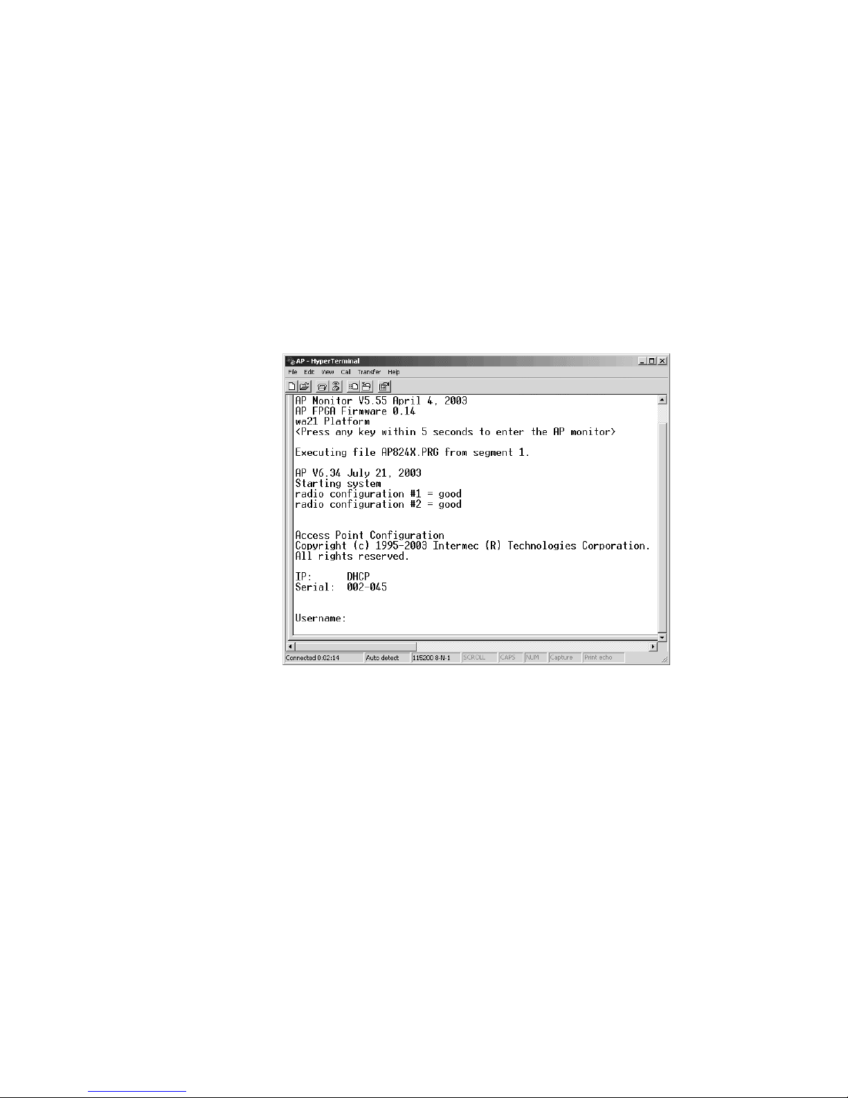
Chapter 1 — Getting Started
2 Start the communications program and configure the serial port
communications parameters on your PC, and then click OK. You
should configure the serial port communications parameters to:
Bits per second 115200
Data bits 8
Parity None
Stop bit 1
Flow control None
3 Connect the access point to power. The access point has no On/Off
switch, so it boots as soon as you apply power.
4 Press Enter when the message “Starting system” appears on your
PC screen. The Username field appears.
5 In the Username field type the default username Intermec, and then
press Enter.
6 In the Password field type the default password Intermec, and then
press Enter. The Access Point Configuration menu appears.
32 MobileLAN access System Manual
Page 47
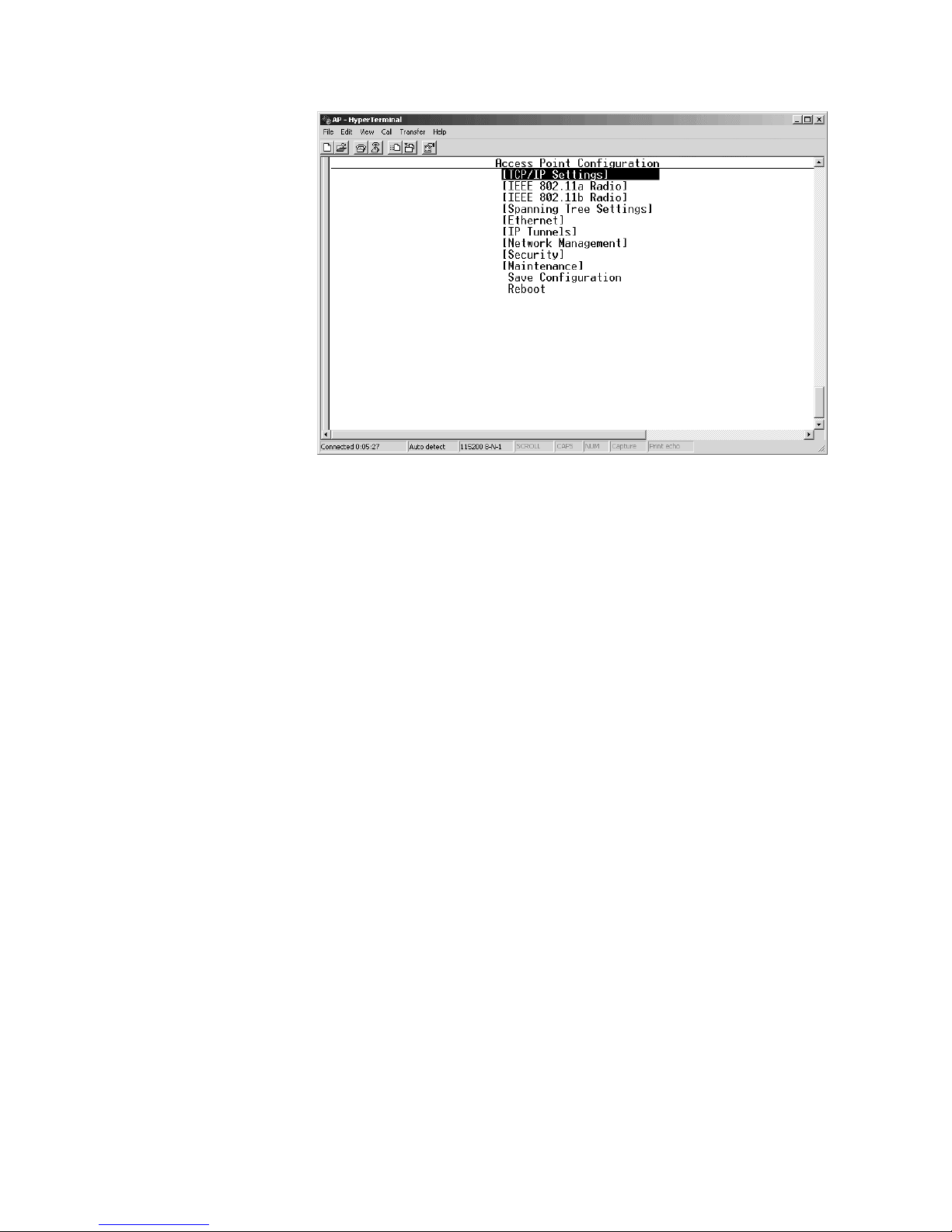
Chapter 1 — Getting Started
7 If you are not using a DHCP server, you need to manually assign an IP
address. Configure these parameters in the TCP/IP Settings menu:
IP Address A unique IP address.
IP Subnet Mask The subnet mask that matches the other devices in your
network.
IP Router
(Gateway)
If the access point will communicate with devices on another
subnet, enter the address of the router that will forward
frames.
Or, if you are using a DHCP server to automatically assign an IP
address to your access point, configure these parameters in the TCP/IP
Settings menu:
DHCP Mode Set to <Use DHCP if IP Address is Zero>.
DHCP Server
Name
The name of the DHCP server that the access point is to
access for automatic address assignment. If no server name is
specified, the access point responds to offers from any server.
8 Press Esc to return to the Access Point Configuration menu.
9 Choose Save Configuration.
10 Choose Reboot.
When the access point is done rebooting, you are ready to install the access
point in your network. See Chapter 2, “Installing the Access Points.”
MobileLAN access System Manual 33
Page 48
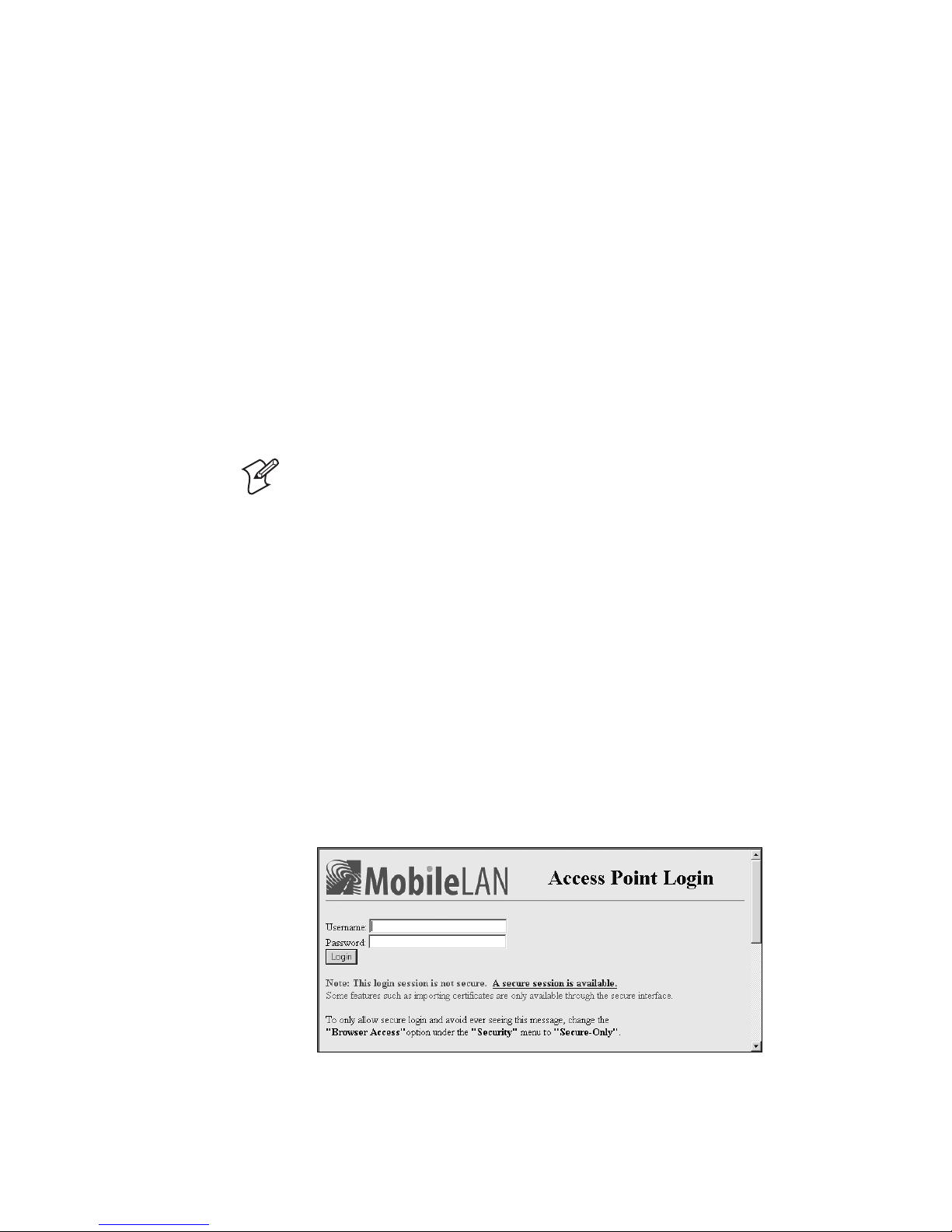
Chapter 1 — Getting Started
Using a Web Browser Interface
After you have set the initial IP address, you can configure, manage, and
troubleshoot the access point from a remote location using a web browser
interface. The web browser interface has been tested using Internet
Explorer v3.0 and later and Netscape Communicator v4.0 and later.
Remotely accessing the access point using other browsers may provide
unpredictable results.
Only one session can be active with the access point at a time. If your
session terminates abruptly or a new login screen appears, someone else
may have accessed the access point. When using the web browser interface,
keep the following points in mind:
• Your session terminates if you do not use it for 15 minutes.
• Command Console mode is not available.
Note: If you access the Internet using a proxy server, you must add the IP
address of the access point to your Exceptions list. The Exceptions list
contains the addresses that you do not want to use with a proxy server.
To use a web browser interface
1 Determine the IP address of the access point. If a DHCP server assigned
the IP address, you must get the IP address from the DHCP server.
2 Start the web browser application.
3 Access the access point using one of these methods:
• In the Address field (Internet Explorer) or in the Location field
(Netscape Communicator), enter the IP address, and press Enter.
• From the File menu, choose Open (Internet Explorer) or choose
Open Page (Netscape Communicator). In the field, enter the IP
address and press Enter.
The Access Point Login screen appears.
34 MobileLAN access System Manual
Page 49
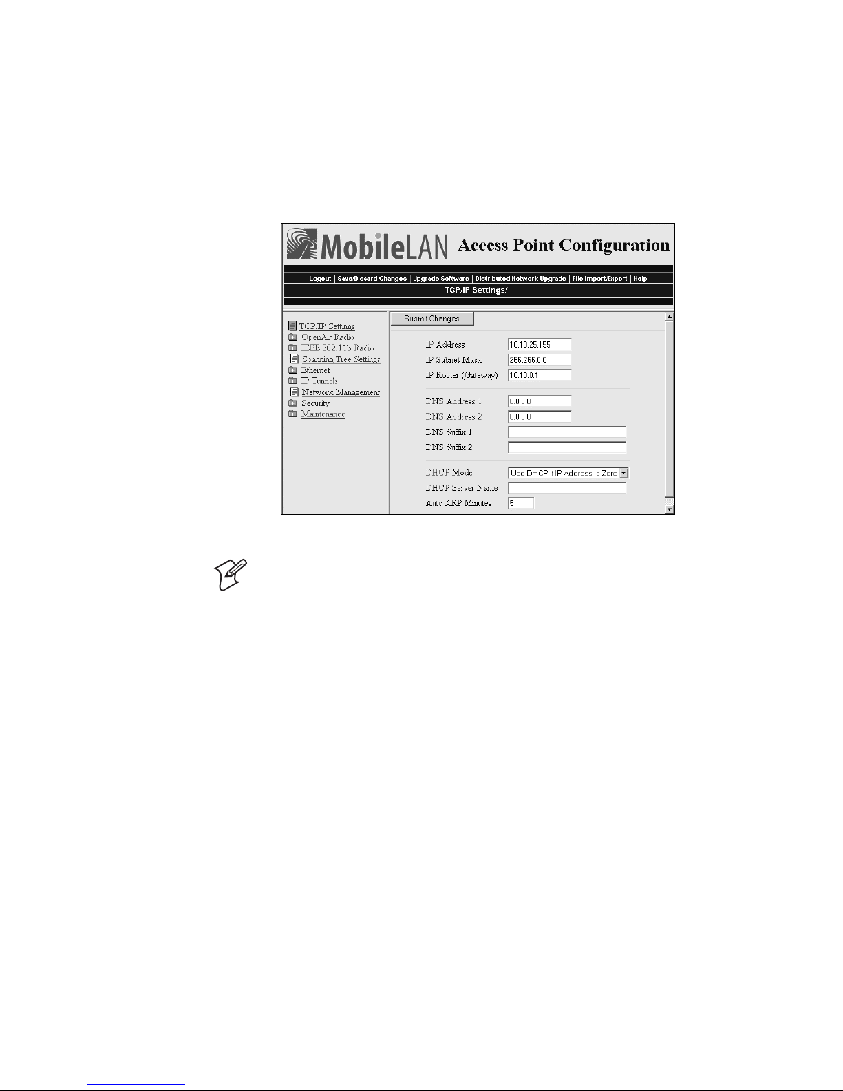
Chapter 1 — Getting Started
4 If necessary, enter a user name and a password. The default username is
Intermec and the default password is Intermec. You can define a user
name and password. For help, see “Setting Up Logins” in Chapter 6.
Or, you may want to log in to a secure session.
5 Click Login. The TCP/IP Settings screen appears.
Your web browser session is established.
Note: Although you can use several different methods to manage the
access point remotely, this manual assumes you are using a web browser.
Using a Telnet Session
After you have configured the IP address, you can configure, manage, and
troubleshoot the access point from a remote location using a telnet session.
Only one session can be active with the access point at a time. If your
session terminates abruptly or a new login screen appears, someone else
may have accessed the access point. Also, your session terminates if you do
not use it for 15 minutes.
To use a telnet session
1 Determine the IP address of the access point. If a DHCP server assigned
the IP address, you must get the IP address from the DHCP server.
2 From a command prompt, type
telnet IPaddress
where IPaddress is the IP address of the access point.
3 Press Enter.
MobileLAN access System Manual 35
Page 50

Chapter 1 — Getting Started
4 If necessary, enter the user name and press Enter. Then, enter the
password and press Enter. The default username is Intermec and the
default password is Intermec. You can define a user name and password.
For help, see “Setting Up Logins” in Chapter 6.
The Access Point Configuration menu appears.
Your telnet session is established.
Saving Configuration Changes
When you are done configuring the access point, you may want to activate
your changes immediately or you may want to save the changes now and
activate them later. If you choose to activate the changes later, they will
become active the next time the access point is booted.
Access Point Configuration Files
Configuration File Description
Default This configuration file is the factory default configuration.
Current
Active
For help, see “Restoring the Access Point to the Default
Configuration” in Chapter 8.
When you click Submit Changes, the access point updates
the current configuration file. The access point does not
change the active configuration file. You can see a list of
pending changes when you click Save/Discard Changes.
Having separate files for the current and active configurations
lets you make changes while the access point is running
without interrupting communication.
When you click Save/Discard Changes > Save Changes and
Reboot, the access point copies the current configuration file
to the active configuration file. The active configuration file is
the file that the access point uses.
36 MobileLAN access System Manual
Page 51
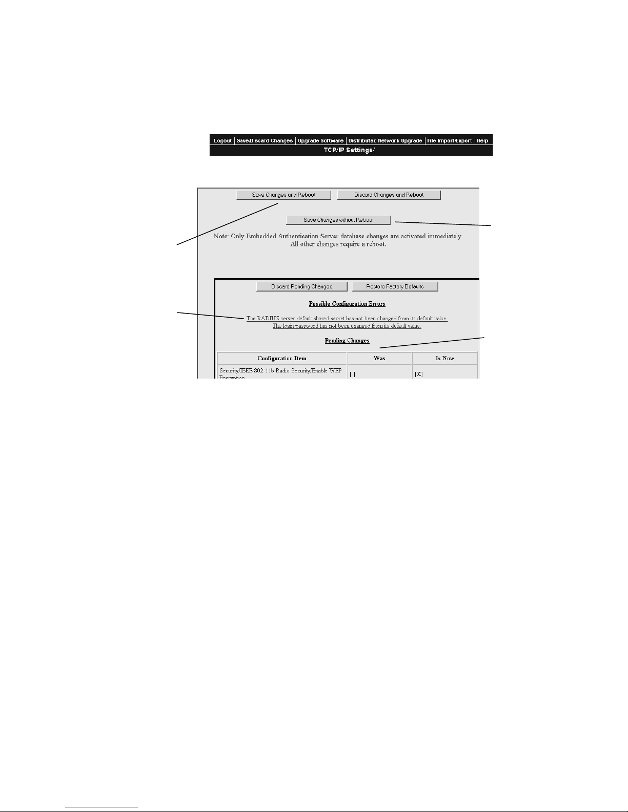
Chapter 1 — Getting Started
g
Using a Web Browser Interface
1 On the menu bar, click Save/Discard Changes.
This screen appears.
Click to use your new
configuration now.
Lists possible
configuration changes
you may still need to
make.
Lists confi
changes you have
made.
Click to use your
new configuration
the next time you
reboot the access
point.
uration
2 Verify that all your configuration changes appear in the Pending
Changes box.
3 Click Save Changes and Reboot to reboot the access point and
immediately use your new active configuration.
Or, click Save Changes without Reboot. The access point saves the
changes to its current configuration and continues to run its active
configuration. You will need to reboot the access point when you want
the current configuration to become the active configuration.
To discard the changes
• Click Discard Pending Changes.
Using a Telnet Session
1 From the Access Point Configuration menu, choose Save
Configuration.
2 Choose Reboot to reboot the access point and immediately use your
new active configuration.
MobileLAN access System Manual 37
Page 52

Chapter 1 — Getting Started
38 MobileLAN access System Manual
Page 53

Installing the Access Points
2
This chapter explains how to install the MobileLAN access products in
your data collection network, provides some tips on how to position access
points to improve your network performance, and provides some external
antenna guidelines. This chapter covers these topics:
• Installation guidelines
• Installing the access points
• Connecting to your fiber optic network
• Connecting power over Ethernet
• External antenna placement guidelines
MobileLAN access System Manual 39
Page 54

Chapter 2 — Installing the Access Points
Installation Guidelines
Intermec recommends that you have Intermec-certified RF specialist
conduct a site survey to determine the ideal locations for all your Intermec
wireless network devices. To conduct a proper site survey, you need to
have special equipment and training.
The following general practices should be followed in any installation:
• Locate access points centrally within areas requiring coverage.
• Overlap access point radio coverage areas to avoid coverage holes.
• Position the access point so that its LEDs are visible. The LEDs are
useful for troubleshooting.
• Install wired LAN cabling within node limit and cable length
limitations.
• Use an uninterruptible power supply (UPS) when AC power is not
reliable.
Microwave Ovens
Proper antenna placement can help improve range. For information about
antenna options, contact your local Intermec representative. For more
guidelines, see “External Antenna Placement Guidelines” on page 54.
When determining ideal locations for the access points, be aware that you
may see network performance degradation from microwave ovens, cordless
telephones, and other access points. For more information, see the next
sections.
Note: Microwave ovens, cordless telephones, and other access points do
not degrade the network performance of the 802.11a radio.
Microwave ovens operate in the same frequency band as 802.11b and
OpenAir radios; therefore, if you use a microwave oven within range of
your wireless network, you may notice network performance degradation.
Both your microwave oven and your wireless network will continue to
function, but you may want to consider relocating your microwave oven
out of range of your access point.
For the 802.11b radio, the access point has a Microwave Oven Robustness
parameter that you can enable to minimize potential interference between
your microwave oven and your wireless network. For help, see
“Configuring 802.11b Radio Advanced Parameters” in Chapter 4.
40 MobileLAN access System Manual
Page 55

Cordless Telephones
If you have an 802.11b, OpenAir, or 902 MHz radio in your access point,
the radio may experience interference from some cordless telephones. For
optimal performance, consider operating cordless telephones out of range
of your access points.
Other Access Points
Access points that are configured for the same frequency and that are in
the same radio coverage area may interfere with each other and decrease
throughput. You can reduce the chance of interference by configuring
access points at least 5 channels apart, such as channels 1, 6, and 11.
Installing the WA22
You can place the WA22 horizontally on a desk or counter. The WA22
also ships with a mounting bracket that lets you mount it vertically to a
wall. Additional mounting options that you can use with the mounting
bracket include a cubicle bracket that lets you mount the WA22 on a
cubicle wall or in a locking bracket.
Chapter 2 — Installing the Access Points
• Cubicle bracket kit (P/N 069926)
• Locking bracket kit (P/N 070184)
To order one of these kits, contact your Intermec representative. Intermec
also offers a variety of antennas and antenna accessories. For more
information, see “Antennas and Antenna Accessories” in Appendix A.
To install the WA22
1 Attach the antenna or antennas. For more information, see “External
Antenna Placement Guidelines” on page 54.
Note: If the WA22 has an 802.11a full-range radio, you must use the
antennas that are already attached to the antenna connectors.
2 Mount the WA22. For help see the MobileLAN access WA22 Quick Start
Guide and the instructions that shipped with the bracket kit.
3 Connect the WA22 to your wired LAN (unless you are using it as a
WAP). For help, see “Connecting the WA22 to Your Wired LAN and
Power” on page 42.
4 Connect the WA22 to power. For help, see “Connecting the WA22 to
Your Wired LAN and Power” on page 42.
When you are done installing the access points, you need to configure
them to communicate with your network.
MobileLAN access System Manual 41
Page 56

Chapter 2 — Installing the Access Points
Connecting the WA22 to Your Wired LAN and Power
Unless you are using the WA22 as a WAP, you must connect it to your
Ethernet or fiber optic network. To connect the WA22 to your fiber optic
network, you must have a WA22 with the fiber optic option. For help, see
“Connecting to Your Fiber Optic Network” on page 50.
To connect the WA22 to your Ethernet network and to power, you must
first connect it to a MobileLAN power bridge, a Cisco power bridge, or
another 802.3af-power bridge. For help, see “Connecting Power Over
Ethernet” on page 53 and the documentation that shipped with your
power bridge.
Installing the 2101
You can place the 2101 horizontally on a desk or counter. The 2101 also
ships with a mounting bracket that lets you mount it vertically to a wall.
Additional mounting options include a desk bracket that lets you mount
the 2101 upright on a desk or counter, a cubicle bracket that lets you
mount the 2101 on a cubicle wall, and a locking bracket. These optional
mounting brackets and accessories are available:
• Desk bracket kit (P/N 069657)
• Cubicle bracket kit (P/N 069926)
• Locking bracket kit (P/N 070184)
• Dual antenna bracket kit (P/N 069888)
• Power supply holder kit (P/N 069893)
To order one of these kits, contact your Intermec representative. To
mount the 2101, follow the instructions in the kit. Intermec offers a
variety of antennas and antenna accessories. For more information, see
“Antennas and Antenna Accessories” in Appendix A.
To install the 2101
1 Attach the antenna or antennas. If you attach only one antenna to the
802.11b radio, you must attach it to the | (send/receive) port. For more
information, see “External Antenna Placement Guidelines” on page 54.
2 Mount the 2101. For help see the MobileLAN access 2101 Quick Start
Guide and the instructions that shipped with the bracket kit.
3 Connect the 2101 to your wired LAN (unless you are using it as a
WAP). For help, see “Connecting the 2101 to Your Wired LAN” on
page 43.
4 Connect the 2101 to power. For help, see “Connecting the 2101 to
Power” on page 43.
42 MobileLAN access System Manual
Page 57

When you are done installing the access points, you need to configure
them to communicate with your network.
Connecting the 2101 to Your Wired LAN
Unless you are using the 2101 as a WAP, you must connect it to your
Ethernet or fiber optic network. To connect the 2101 to your fiber optic
network, you must have a 2101 with the fiber optic option. For help, see
“Connecting to Your Fiber Optic Network” on page 50.
To connect the 2101 to your Ethernet network
• Attach one end of the Ethernet cable to the 10BaseT/100BaseTx port
on the 2101, and attach the other end to your Ethernet network or a
MobileLAN splitter (if you are using the power over Ethernet option).
Connecting the 2101 to Power
You use a power supply and power cord to connect the 2101 directly to an
AC power outlet.
Chapter 2 — Installing the Access Points
If you are using the power over Ethernet option, you must have the
MobileLAN power splitter and the MobileLAN power bridge. For help,
see “Connecting Power Over Ethernet” on page 53 and the
documentation that shipped with your splitter and power bridge.
To connect the 2101 to power
You must use the appropriate Intermec power supply with this device
or equipment damage may occur.
Attention: Vous devez utiliser la source d’alimentation Intermec
adéquate avec cet appareil sinon vous risquez endommager
l’équipement.
1 Plug one end of the power supply into the power port on the 2101.
2 Plug one end of the power cord into the power supply and the other
end into an AC power outlet.
The access point boots as soon as you apply power.
MobileLAN access System Manual 43
Page 58

Chapter 2 — Installing the Access Points
Installing the WA21
You can place the WA21 horizontally or vertically on a desk or counter. If
you want to mount the WA21 to a wall or beam using an Intermec
mounting bracket kit, you need one of these mounting kits:
• Mounting bracket kit (P/N 068918)
• Rotating mounting bracket kit (P/N 068751)
To order one of these kits, contact your Intermec representative.
To maintain the IP54 environmental rating, you must mount the WA21
in either the horizontal or vertical position. If you order the WA21 with
the heater option, you must use one of the mounting bracket kits to
mount the WA21 with the LEDs facing down.
A variety of external antenna options are available for the WA21. Contact
your Intermec representative for information about the various antenna
options, including higher gain and directional antennas. For more
information about antennas and antenna accessories, see “Antennas and
Antenna Accessories” in Appendix A.
To install the WA21
1 Attach the antenna or antennas. For more information, see “External
Antenna Placement Guidelines” on page 54.
Note: If the WA21 has an 802.11a full-range radio, you must use the
antennas that are already attached to the antenna connectors.
2 Mount the WA21. For help see the MobileLAN access WA21 Quick Start
Guide and the instructions that shipped with the bracket kit.
3 Connect the WA21 to your wired LAN (unless you are using it as a
WAP). For help, see “Connecting the WA21 to Your Wired LAN” on
page 45.
4 Connect the WA21 to power. For help, see “Connecting the WA21 to
Power” on page 45.
When you are done installing the access points, you need to configure
them to communicate with your network.
44 MobileLAN access System Manual
Page 59

Connecting the WA21 to Your Wired LAN
Unless you are using the WA21 as a WAP, you need to connect it to your
Ethernet or fiber optic network. To connect the WA21 to your fiber optic
network, you must have a WA21 with the fiber optic option. For help, see
“Connecting to Your Fiber Optic Network” on page 50.
To connect the WA21 to the Ethernet network
• Attach one end of the Ethernet cable to the 10BaseT/100BaseTx port
on the WA21 and attach the other end to your Ethernet network or a
MobileLAN power bridge (if you are using power over Ethernet), a
Cisco power bridge or another 802.3af-compliant power bridge.
Connecting the WA21 to Power
If your WA21 has the internal power supply option, you can use a power
cord to connect the WA21 directly to an AC power outlet.
If you are using the power over Ethernet option, you must have the
MobileLAN power bridge, a Cisco power bridge, or another 802.3afpower bridge. For help, see “Connecting Power Over Ethernet” on page
53 and the documentation that came with your power bridge.
Chapter 2 — Installing the Access Points
To connect the WA21 to power
• Plug one end of the power cord into the power port on the WA21 and
plug the other end into an AC power outlet. The access point boots as
soon as you apply power.
Installing the 2100
You can place the 2100 horizontally or vertically on a desk or counter. If
you want to mount the 2100 to a wall or beam using an Intermec
mounting bracket kit, you need one of these mounting kits:
• Mounting bracket kit (P/N 068918)
• Rotating mounting bracket kit (P/N 068751)
To order one of these kits, contact your Intermec representative.
To maintain the IP54 environmental rating, you must mount the 2100 in
either the horizontal or vertical position. If you order the 2100 with the
heater option, you must use one of the mounting bracket kits to mount
the WA21 with the LEDs facing down.
A variety of external antenna options are available for the 2100. Contact
your Intermec representative for information about the various antenna
options, including higher gain and directional antennas. For more
information about antennas and antenna accessories, see “Antennas and
Antenna Accessories” in Appendix A.
MobileLAN access System Manual 45
Page 60

Chapter 2 — Installing the Access Points
To install the 2100
1 Attach the antenna or antennas. For more information, see “External
Antenna Placement Guidelines” on page 54.
2 Mount the 2100. For help see the MobileLAN access 2100 Quick Start
Guide and the instructions that shipped with the bracket kit.
3 Connect the 2100 to your wired LAN (unless you are using it as a
WAP). For help, see “Connecting the 2100 to Your Wired LAN” in the
next section.
4 Connect the 2100 to power. For help, see “Connecting the 2100 to
Power” later in this chapter.
When you are done installing the access points, you need to configure
them to communicate with your network.
Connecting the 2100 to Your Wired LAN
Unless you are using the 2100 as a WAP, you need to connect it to your
Ethernet or fiber optic network. To connect the 2100 to your fiber optic
network, you must have a 2100 with the fiber optic option. For help, see
“Connecting to Your Fiber Optic Network” on page 50.
To connect the 2100 to the Ethernet network
• Attach one end of the Ethernet cable to the 10BaseT/100BaseTx port
on the 2100 and attach the other end to your Ethernet network.
Connecting the 2100 to Power
You use a power cord to connect the 2100 directly to an AC power outlet.
To connect the 2100 to power
• Plug one end of the power cord into the power port on the 2100 and
plug the other end into an AC power outlet. The access point boots as
soon as you apply power.
46 MobileLAN access System Manual
Page 61

Installing the 2102/2106
You can install the 2102 or the 2106 horizontally on a desk or counter, or
you can install it vertically to a wall using the mounting bracket that ships
with it. An optional cubicle bracket is also available for mounting the 2102
or the 2106 on a cubicle wall. These optional mounting bracket kits and
accessories are available for the 2102 or the 2106:
• Cubicle bracket kit (P/N 070366)
• Power supply holder kit (P/N 069893)
This optional mounting bracket kit is available for the 2102:
• Dual antenna bracket kit (P/N 069888)
Intermec also offers a variety of antennas and antenna accessories,
including diversity antennas. For more information, see “Antennas and
Antenna Accessories” in Appendix A. Contact your Intermec
representative for more information about ordering access point
accessories.
Chapter 2 — Installing the Access Points
To install the 2102 or 2106
1 Mount the 2102 or 2106. For help see the MobileLAN access 2102
Quick Start Guide or the MobileLAN access 2106 Quick Start Guide and
the instructions that shipped with your bracket kit.
2 Position or install the antenna. For help, see “Positioning the Standard
Antenna” or “Attaching an External Antenna (2102)” on pages 47-48.
3 Connect the 2102 or 2106 to your wired LAN (unless you are using it
as a WAP). For help, see “Connecting the 2102 or 2106 to Your
Ethernet Network” on page 49.
4 Connect the 2102 or 2106 to power. For help, see “Connecting the
2102 or 2106 to Power” on page 49.
When you are done installing the access points, you need to configure
them to communicate with your network.
Positioning the Standard Antenna
The 2102 and the 2106 feature a built-in standard antenna that rotates
180° as shown in the next illustration. Use these guidelines when
positioning the antenna.
Note: Do not force the antenna past the hard stop at 0° or 180° or you
may break the antenna connector.
• Place the antenna at 0° when storing the 2102 or the 2106.
• Place the antenna at 90° when using the 2102 or the 2106 horizontally;
for example, when the 2102 is positioned on a desk or counter.
MobileLAN access System Manual 47
Page 62
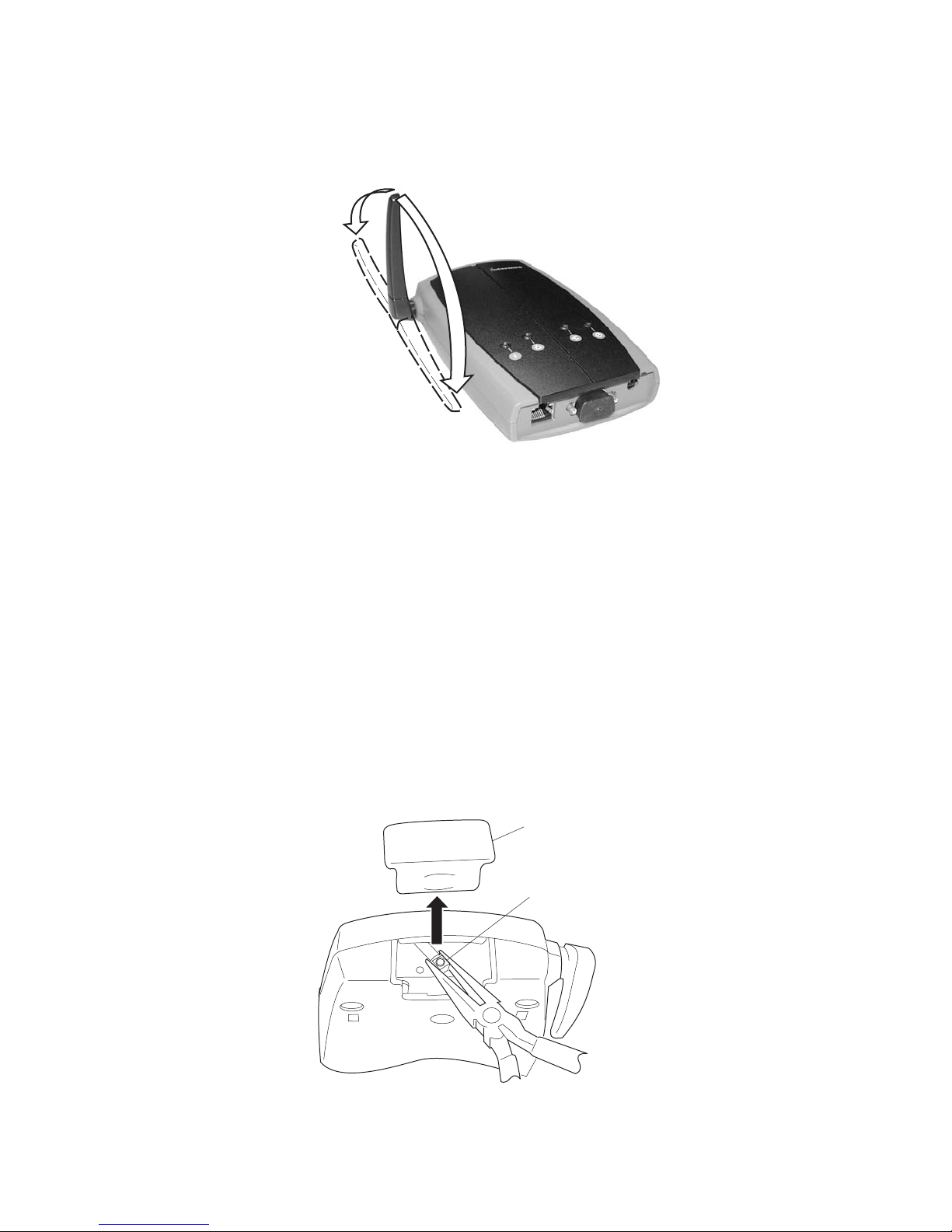
Chapter 2 — Installing the Access Points
• Place the antenna at 180° when using the 2102 or the 2106 vertically;
for example, when it is mounted on a wall or cubicle.
90°
180°
0°
Antenna positions on the 2102 and 2106: This illustration shows the different ways
that you can position the antenna on the 2102 and 2106.
2102G015.eps
Attaching an External Antenna (2102)
To attach an external antenna to the 2102, you must first disconnect the
built-in antenna, and then attach an antenna cable directly to the radio
card. You need this tool:
• Needle-nose pliers
To attach an external antenna
1 Remove the radio card door.
2 Pull straight up on the antenna wire to disconnect it from the radio
card.
Door
Antenna
wire
48 MobileLAN access System Manual
21XXT010.eps
Page 63

Chapter 2 — Installing the Access Points
3 Tuck the antenna wire inside the 2102 housing.
4 Remove the punch-out tab from the door.
Door
Punch-out
tab
Pliers
21XXT009.eps
5 Attach the antenna cable to the radio by inserting the cable connector
into the radio card.
6 Replace the door.
Connecting the 2102 or 2106 to Your Ethernet Network
If you purchased the MobileLAN power splitter and the MobileLAN
power bridge so that you can use power over Ethernet, see “Connecting
Power Over Ethernet” on page 53.
To connect the 2102 or the 2106 to your Ethernet network
• (2102) Attach one end of the 10BaseT cable to the 10BaseT port on the
2102, and attach the other end to your Ethernet network.
(2106) Attach one end of the Ethernet cable to the 10BaseT/100BaseTx
port on the 2106 and attach the other end to your Ethernet network.
Connecting the 2102 or 2106 to Power
You use a power supply and power cord to connect the 2102 or the 2106
directly to an AC power outlet.
If you are using the power over Ethernet option, you must have the
MobileLAN power splitter and the MobileLAN power bridge. For help,
see “Connecting Power Over Ethernet” on page 53 and the
documentation that shipped with your splitter and power bridge.
Note: The 2102 and 2106 use different power cords.
MobileLAN access System Manual 49
Page 64

Chapter 2 — Installing the Access Points
To connect the 2102 or the 2106 to power
You must use the appropriate Intermec power supply with this device
or equipment damage may occur.
Attention: Vous devez utiliser la source d’alimentation Intermec
adéquate avec cet appareil sinon vous risquez endommager
l’équipement.
1 Plug one end of the power supply into the power port on the 2102 or
the 2106.
2 Plug one end of the power cord into the power supply and plug the
other end into an AC power outlet.
The access point boots as soon as you apply power.
Connecting to Your Fiber Optic Network
You can order your WA22, 2101, WA21, or 2100 access points with a
fiber optic option. To connect the access point with the fiber optic option
to your fiber optic network, you must have a patch cord and an adapter.
Patch cords and adapters are available from many different manufacturers.
Using adapters and patch cords, you can connect your access point to:
• an MT-RJ network.
• a square connector (SC) network.
• a straight tip (ST) network.
For help choosing the proper cord and adapter, contact your local
Intermec representative.
Note: All cables must be multimode, 62.5/125 µm.
Connecting to an MT-RJ Network
To connect to an MT-RJ network, you need:
• a patch cord for connecting the MT-RJ transceiver to the MT-RJ
adapter.
• an adapter for connecting an MT-RJ cord to an MT-RJ network.
50 MobileLAN access System Manual
Page 65
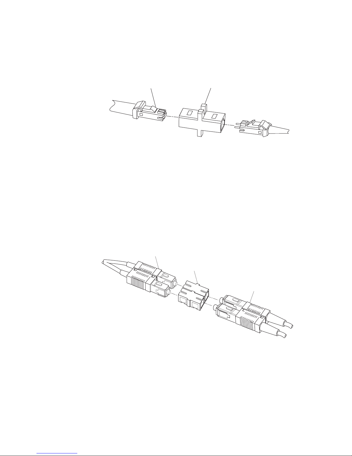
Chapter 2 — Installing the Access Points
k
k
To connect to an MT-RJ network
1 Remove any cable protectors attached to the patch cord and adapter.
2 Connect the access point to your network.
To
access
point
Connecting to an SC Network
To connect to an SC network, you need:
• a patch cord for connecting the MT-RJ transceiver to the SC adapter.
• an adapter for connecting an SC cord to an SC network.
To connect to an SC network
1 Remove any cable protectors attached to the patch cord and adapter.
2 Connect the access point to your network as shown in the next
illustrations.
MT-RJ connector
MT-RJ adapter
21XXU039.eps
To
MT-RJ
networ
To access
point
SC connector
21XXU040.eps
SC adapter
SC connector
To SC
networ
MobileLAN access System Manual 51
Page 66

Chapter 2 — Installing the Access Points
k
k
SC connector
To
access
point
SC adapter
SC connector
To
SC networ
Connecting to an ST Network
To connect to an ST network, you need:
• a patch cord for connecting the MT-RJ transceiver to the ST adapter.
• an adapter for connecting an ST cord to an ST network.
To connect to an ST network
1 Remove any cable protectors attached to the patch cord and adapter.
2 Connect the access point to your network.
To
access
point
ST connector
21XXU041.eps
ST adapter
To
SC network
ST connector
To
ST networ
52 MobileLAN access System Manual
21XXU042.eps
To
ST network
Page 67

Connecting Power Over Ethernet
The WA22 is powered by power over Ethernet. The WA21 can be
powered by AC power or by power over Ethernet or both. You can power
the 2101, 2102, or 2106 using power over Ethernet if you connect them
to a MobileLAN splitter. For all access points, you need a power bridge.
You order the splitter and the power bridges as accessories:
• (2101, 2102) MobileLAN power splitter, 5 VDC (P/N 071581)
• (2106) MobileLAN power splitter, 3.3 VDC (P/N 072158)
For a list of the power bridges that Intermec sells, contact your local
Intermec representative.
You connect the splitter to the power bridge using a typical Ethernet cable
(CAT5). In this cable, four twisted pair lines are used for data and four are
unused. Using the data lines, data simply passes through the splitter. Using
the unused lines, the splitter receives power from the power bridge, which
it converts to the input voltage required by the access point (5 VDC or
3.3 VDC). An LED on the splitter lights when power is being supplied to
the access point.
Chapter 2 — Installing the Access Points
To A C
MobileLAN
power bridge
Data In
MobileLAN™power
Not
Active
Active
Power & Data Out
Main
To Ethernet
MobileLAN
splitter
21XXT075.eps
Connecting 2101 using power over Ethernet: This illustration shows how you
connect the 2101 to the MobileLAN splitter and a power bridge so that you can run
power over Ethernet.
MobileLAN access System Manual 53
Page 68

Chapter 2 — Installing the Access Points
To connect power over Ethernet
1 Install the power bridges. For help, see the documentation that shipped
with the power bridge.
2 (2101, 2102, 2106) Connect the splitter to the Ethernet port and to the
power port of the access point.
3 (2101, 2102, 2106) Use an Ethernet cable to connect the splitter to the
power bridge.
(WA22, WA21) Use an Ethernet cable to connect the power bridge to
the Ethernet port of the access point.
External Antenna Placement Guidelines
Antennas and their placement play a vital role when installing a wireless
network. Every wireless network environment presents its own unique
obstacles. Therefore, the exact range that you will achieve with each access
point is difficult to determine. Intermec recommends that you allow an
Intermec-certified RF specialist to perform a site survey before you install a
wireless network. For more information, contact your local Intermec
representative.
Radio signals may reflect off some obstacles and be absorbed by others. For
example, two radios may achieve up to 305 m (1,000 ft) of range if
positioned outdoors within line of sight, with no obstacles between them.
However, the same two radios may only achieve 152 m (500 ft) of range
when the RF signal has to travel through items such as cubicles. If the
signal must penetrate office walls, the signal range may decrease to 91 m
(300 ft).
Using the proper antennas for your environment and placing them in the
proper areas can help improve range. For information about antenna
options, contact your local Intermec representative. Here are some general
guidelines for positioning antennas:
• Place the antenna as high as possible. In an office environment, try to
place it above cubicle walls.
• Do not place a sheet of metal (such as a filing cabinet) between two
antennas.
These next sections provide detailed information about antenna placement
for those access points that can have more than one antenna.
54 MobileLAN access System Manual
Page 69

Chapter 2 — Installing the Access Points
Positioning Antennas for 802.11b and 802.11a Radios
The 802.11b radios have two ports: one is a transmit/receive port and the
other is a receive-only port. The 802.11a radios have two ports; both ports
are transmit/receive ports. Intermec recommends that you use two
antennas for optimal performance of the 802.11b and 802.11a radios. If
you only attach one antenna to the 802.11b radio, you must attach it to
the transmit/receive port.
On the WA22 and the WA21, use antenna connectors 1 and 2 or 3 and 4
to attach antennas to the send/receive ports. On the 2100, use antenna
connectors 1 and 3 or 2 and 4 to attach antennas to the send/receive ports.
On the 2101 and 2102, both antenna ports are visible. The antenna ports
are marked | and ||. Port | is the transmit/receive port; port || is the receiveonly port.
Note: The antenna diversity system uses only one antenna at a time.
Positioning Antennas for Antenna Diversity
Antenna diversity lets you attach two antennas to one radio to increase the
odds of receiving a better signal on either of the antennas. The 802.11b
radio and the 802.11a radio feature antenna diversity. If you are using
antenna diversity, placement of the antennas is critical because each
antenna has a particular function. Antennas placed too close together may
cause interference with each other. Antennas placed too far apart may not
be able to establish two-way communications with other radios.
To achieve optimum placement for the two antennas, you must place the
transmit/receive antenna so that it is within range of all the radios that the
receive-only antenna can hear. Note these important points:
• Use external antennas to achieve the recommended antenna separation
for placement of either omni or directional antennas.
• Position omni antennas for the 802.11b or the 802.11a radio at least
0.61 m (2 ft) apart.
• Position directional antennas so they point in the same direction.
• Position the antennas so that both antennas are within range of the
radios they need to communicate with.
• Do not position the two antennas around a corner or so that a wall is
between them.
• Follow the recommended antenna separation precisely when using the
closest distances. Movement of as little as 3.05 cm (1.2 in) may strongly
affect performance. You should choose the greatest distance possible
within the constraints of your environment.
MobileLAN access System Manual 55
Page 70

Chapter 2 — Installing the Access Points
Recommended Antenna Separation for Antenna Diversity
Location Recommended Antenna Separation
Highly reflective warehouse
environment
Moderately reflective warehouse
environment
Open/Office environment 1.22 m (4 ft) to 3.05 m (10 ft)
Positioning Antennas for Dual Radio Access Points
These recommendations apply to omni antennas; if you are using
directional antennas, you should increase the recommended separation
between the antennas:
• If your access point has two 802.11b or two 802.11a radios, position
the antennas for one radio at least 3.05 m (10 ft) from the antennas for
the other radio.
• If your access point has at least one 802.11b or one 802.11a radio (the
other radio may be any radio), cable the antennas for the 802.11b or
802.11a radio at least 3.05 m (10 ft) from the access point.
0.33 m (13 in) or 0.64 m (25 in)
0.64 m (25 in), 1.22 m (4 ft), or 1.83 m (6 ft)
• If your access point has an 802.11b radio and an 802.11a full-range
radio, cable the antennas for the 802.11b at least 3.05 m (10 ft) from
the access point.
• If your access point has an 802.11b radio and an 802.11a mid-range
radio, cable the antennas for either the 802.11b radio or the 802.11a
radio at least 3.05 m (10 ft) from the access point.
Positioning Antennas for an OpenAir WAP
For OpenAir WAPs, you must use external antennas and position them at
the recommended distances for proper functioning. There are two types of
Intermec-recommended antennas you can use:
• Omni
• Directional
You can position the antennas in one of three ways:
• Horizontal. Both antennas are mounted in the same plane (at the same
height).
• Stacked. One antenna is mounted directly above the other.
• Angled. The two antennas are mounted some distance apart and at
different heights.
56 MobileLAN access System Manual
Page 71

Chapter 2 — Installing the Access Points
You can use two omni antennas, two directional antennas or you can use
one omni antenna and one directional antenna. The following table shows
the minimum distance that must exist between the two antennas.
Recommended Antenna Separation for an OpenAir WAP
Position 2 Omni Antennas 2 Directional Antennas 1 Omni, 1 Directional Antenna
Horizontal 3dBi omni, 3 m (10 ft)
6dBi omni, 6.1 m (20 ft)
9dBi omni, 12.2 m (40 ft)
Stacked 0.6 m (2 ft) (does not apply) 0.6 m (2 ft)
Angled 1.1 m (3.5 ft) vertically and
7.3 m (24 ft) horizontally
Mounting Mount so antennas point
down
3 m (10 ft) 6.1 m (20 ft)
0.6 m (2 ft) vertically and
3 m (10 ft) horizontally
Mount antennas back-toback.
0.6 m (2 ft) vertically and
6.1 m (20 ft) horizontally
If antennas are not stacked, mount
the directional antenna pointing
away from the omni antenna.
If the antennas are stacked, mount
the directional antenna above the
omni antenna.
MobileLAN access System Manual 57
Page 72

Chapter 2 — Installing the Access Points
58 MobileLAN access System Manual
Page 73

Configuring the Ethernet
3
This chapter explains how to configure the MobileLAN access products so
that they communicate with your Ethernet network. This chapter explains:
• Configuring TCP/IP settings
• Configuring other Ethernet or fiber optic settings
• Configuring Ethernet filters
Network
MobileLAN access System Manual 59
Page 74
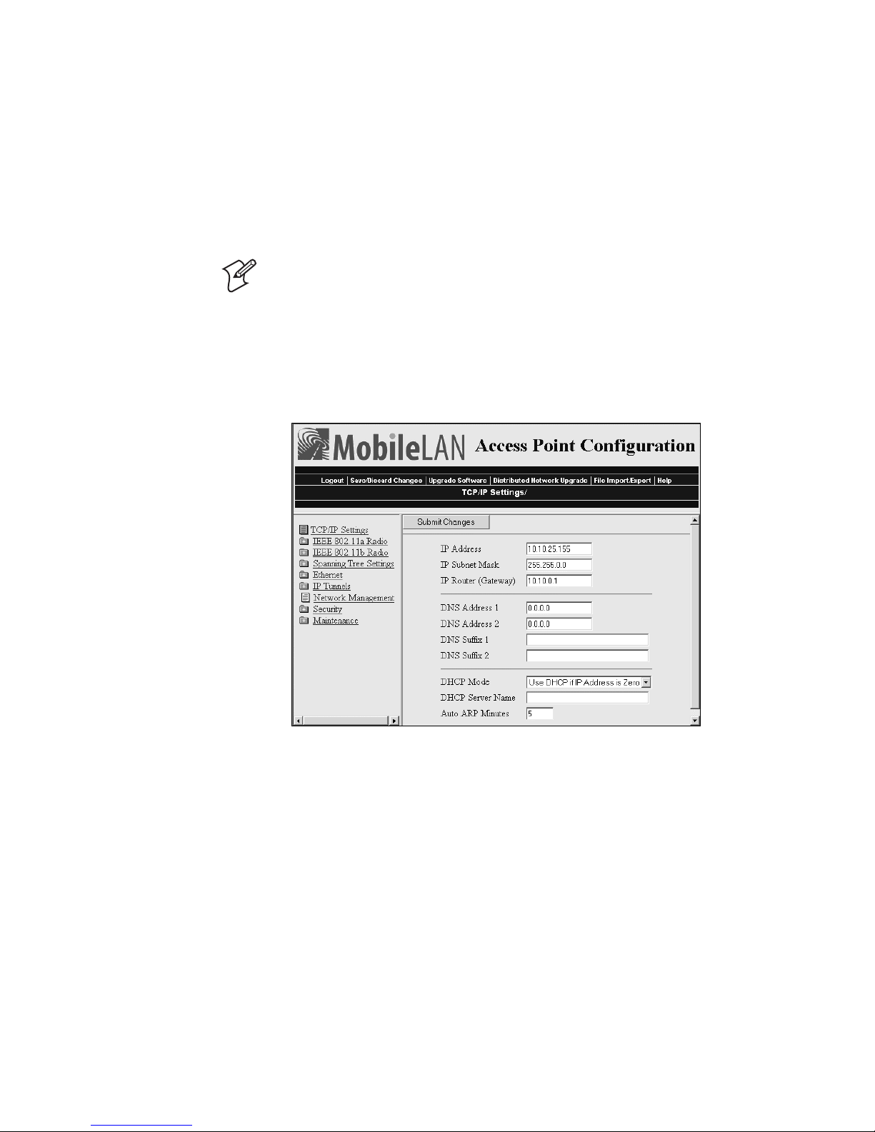
Chapter 3 — Configuring the Ethernet Network
Configuring the TCP/IP Settings
If you are using a DHCP server to automatically assign an IP address to
the access point, go to “Configuring the Access Point as a DHCP Client”
on page 61. If you are not using a DHCP server, you need to manually
assign some TCP/IP parameters.
Note: You should have already configured an IP address for the access
point. For help, see “Configuring the Access Point (Setting the IP
Address)” in Chapter 1.
To configure the TCP/IP settings
1 From the menu, click TCP/IP Settings. The TCP/IP Settings screen
appears.
2 Configure the TCP/IP settings. For help, see the next table.
3 If you want to configure the access point as a DHCP server, see
“Configuring the Access Point as a DHCP Server” on page 62.
4 If you want to configure the access point as a NAT server, see “About
Network Address Translation (NAT)” on page 65.
5 If you want to configure the access point to send ARP requests, see
“Configuring the Access Point to Send ARP Requests” on page 66.
6 Click Submit Changes to save your changes. To activate your changes,
from the menu bar click Save/Discard Changes, and then click Save
Changes and Reboot. For help, see “Saving Configuration Changes”
on page 36.
60 MobileLAN access System Manual
Page 75

Chapter 3 — Configuring the Ethernet Network
TCP/IP Settings Descriptions
Parameter Explanation
IP Address Enter the IP address of the access point. The IP address has the form
x.x.x.x, where x is a number from 0 to 255.
IP Subnet Mask Enter the subnet mask that matches the other devices in your
network. The subnet mask has the form x.x.x.x, where x is a number
from 0 to 255.
IP Router
(Gateway)
DNS Address 1 Enter the IP address of a domain name server that the access point
DNS Address 2 Enter the IP address of a domain name server that the access point
DNS Suffix 1 Enter a domain name suffix that will be appended to DNS names
DNS Suffix 2 Enter a domain name suffix that will be appended to DNS names
Enter the IP address of the router that will forward frames if the
access point will communicate with devices on another subnet. The
IP address has the form x.x.x.x, where x is a number from 0 to 255.
uses to resolve DNS names. If this access point is a DHCP server, this
DNS address will be distributed to DHCP clients. You can enter up
to two DNS addresses to be delivered to DHCP clients.
uses to resolve DNS names if the DNS server at DNS Address 1 is
not responding. If this access point is a DHCP server, this DNS
address will be distributed to DHCP clients.
that cannot be resolved. If the access point is a DHCP server, this is
the only DNS suffix that is delivered to DHCP clients.
For example, enter a suffix of UVW.COM. When you try to resolve
ABC, the DNS will look for ABC.UVW.COM.
that cannot be resolved either by themselves or using DNS suffix 1.
For example, enter a suffix of XYZ.COM. When you try to resolve
ABC, the DNS will first look for ABC.UVW.COM and then it will
look for ABC.XYZ.COM.
Configuring the Access Point as a DHCP Client
You can use a DHCP server to automatically assign an IP address and
other TCP/IP settings to your access point; that is, the access point can act
as a DHCP client.
Note: You cannot configure the access point as both a DHCP server and a
DHCP client.
Note: If you are using the embedded authentication server feature, do not
configure the access point as a DHCP client.
To configure the access point as a DHCP client
1 From the menu, click TCP/IP Settings. The TCP/IP Settings screen
appears.
MobileLAN access System Manual 61
Page 76
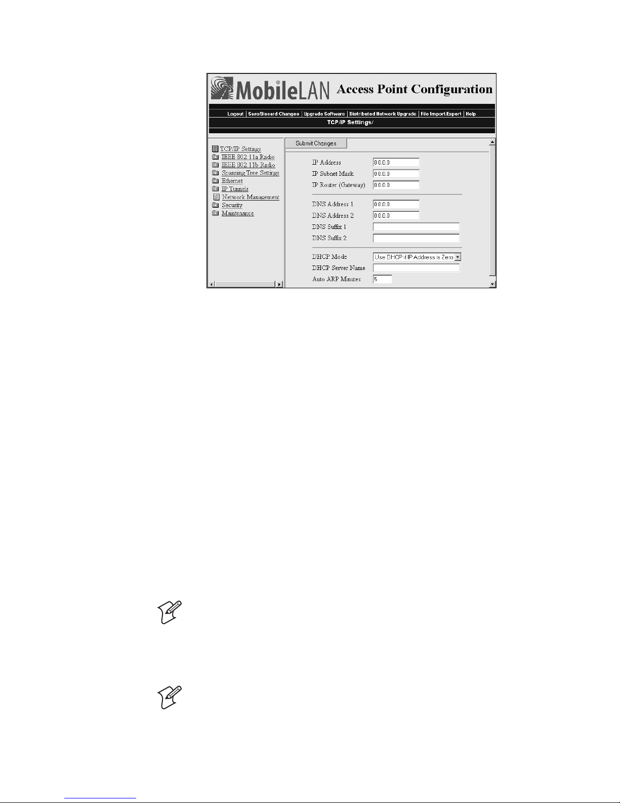
Chapter 3 — Configuring the Ethernet Network
2 In the DHCP Mode field, choose either Always Use DHCP or Use
DHCP if IP Address is Zero. If you choose Use DHCP if IP Address is
Zero, make sure that the IP Address field is 0.0.0.0.
3 In the DHCP Server Name field, enter the name of the DHCP server
that the access point is to access for automatic address assignment. If no
server name is specified, the access point responds to offers from any
server.
4 Click Submit Changes to save your changes. To activate your changes,
from the menu bar click Save/Discard Changes, and then click Save
Changes and Reboot. For help, see “Saving Configuration Changes”
on page 36.
Configuring the Access Point as a DHCP Server
You can configure the access point as a simple DHCP server that provides
DHCP server functions for small installations where no other DHCP
server is available. The DHCP server will offer IP addresses and other
TCP/IP settings to any DHCP client it hears as long as a pool of
unallocated IP addresses is available. These clients may include other access
points, wireless end devices, wired hosts on the distribution LAN, or wired
hosts on secondary LANs.
Note: If you configure the access point as a DHCP server, it is not
intended to replace a general purpose, configurable DHCP server, and it
makes no provisions for synchronizing DHCP policy between itself and
other DHCP servers. Customers with complex DHCP policy
requirements should use other DHCP server software.
Note: You cannot configure the access point as both a DHCP server and a
DHCP client.
62 MobileLAN access System Manual
Page 77
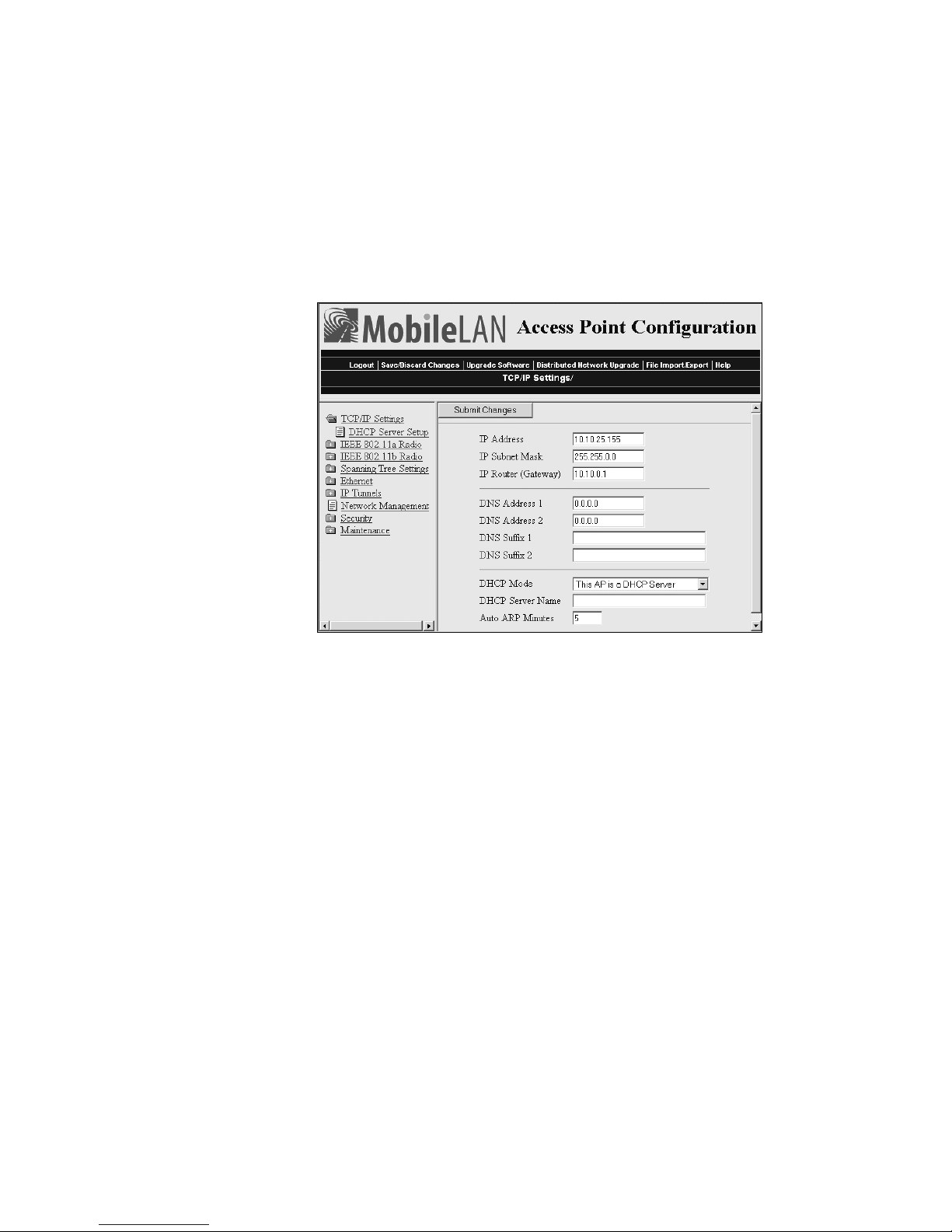
Chapter 3 — Configuring the Ethernet Network
To avoid a single point of failure, you can configure more than one access
point to be a DHCP server; however, the access points do not share
DHCP client databases. You should configure each DHCP server with a
different address pool from which to allocate client IP addresses.
To configure the access point as a DHCP server
1 From the menu, click TCP/IP Settings. The TCP/IP Settings screen
appears.
2 Verify that the IP Address field, IP Subnet Mask field, and IP Router
field are configured. For help, see “Configuring the TCP/IP Settings”
on page 60.
3 In the DHCP Mode field, choose This AP is a DHCP Server.
4 In the DHCP Server Name field, enter the name for this access point
as a DHCP server.
5 Click Submit Changes to save your changes.
6 Click DHCP Server Setup. The DHCP Server Setup screen appears.
MobileLAN access System Manual 63
Page 78
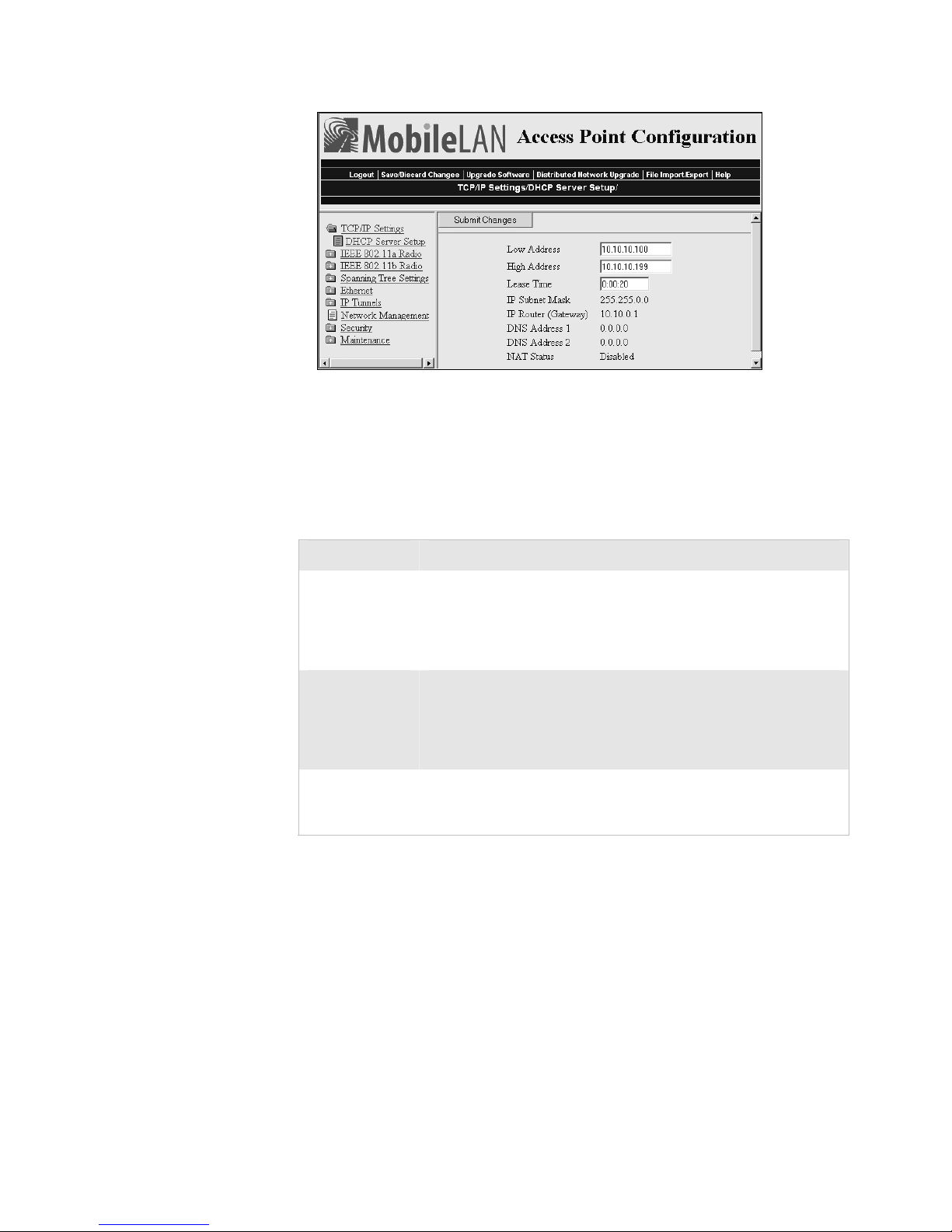
Chapter 3 — Configuring the Ethernet Network
7 Configure the DHCP server. For help, see the next table.
8 Click Submit Changes to save your changes. To activate your changes,
from the menu bar click Save/Discard Changes, and then click Save
Changes and Reboot. For help, see “Saving Configuration Changes”
on page 36.
DHCP Server Setup Parameter Descriptions
Parameter Explanation
Low Address Enter the low IP address in the range of IP addresses available to the
DHCP server for distribution to DHCP clients.
If these addresses are not on the same subnet as the access point, the
access point will perform Network Address Translation (NAT) for
the clients to which it grants IP addresses.
High Address Enter the high IP address in the range of IP addresses available to
the DHCP server for distribution to DHCP clients.
If these addresses are not on the same subnet as the access point, the
access point will perform Network Address Translation (NAT) for
the clients to which it grants IP addresses.
Lease Time Specifies the duration of the leases that are granted by the DHCP
server. Enter the lease time in the format days:hours:minutes.
If you set the lease time to 0, infinite leases are granted.
Supported DHCP Server Options
When the access point is acting as a DHCP server, it issues IP address
leases to configure the IP address, along with the DNS addresses, DNS
suffixes, IP subnet mask, and IP router. These parameters will contain the
same values as those configured for the access point.
64 MobileLAN access System Manual
Page 79

Chapter 3 — Configuring the Ethernet Network
Unsupported DHCP Server Options
When the access point is acting as a DHCP server, it does not support any
DHCP options other than those listed. The DHCP server disregards any
DHCP options that are not explicitly required by the DHCP specification.
The DHCP server ignores all frames with a non-zero giaddr (gateway IP
address). The DHCP server only responds to requests from its own subnet.
About Network Address Translation (NAT)
NAT allows IP addresses to be used by more than one end device. The
access point can act as a NAT server, which instantaneously rewrites IP
addresses and port numbers in IP headers so that frames all appear to be
coming from (or going to) the single IP address of the access point instead
of the actual source or destination.
When an end device uses the access point as an IP router, the access point
replaces the IP header, which includes the device MAC address, IP source
address, and TCP/UDP port, with its own. You can configure the DHCP
server to indicate that the access point is the IP router when the server
allocates an IP address. Special consideration is given to changing the FTP
data connection TCP port number, which is in the body of the TCP
frame. After the frame source is modified, it is forwarded to the proper
subnet.
If the destination subnet is a different subnet from the one the access point
is on, the destination MAC address is changed to the IP router that has
been configured for the access point. If the destination subnet is the same
subnet as the one the access point is on, the access point converts the MAC
address to the MAC address that belongs to the destination IP address.
This may involve using ARP for MAC address discovery.
When the access point receives a frame with its IP address, it identifies the
need for address translation by inspecting the destination port number. If
the port number is within the pool reserved for NAT operation, it looks
up the original MAC address, IP address, and port number. The frame is
then modified and forwarded to the end device.
NAT operation is disabled or enabled automatically depending on the
continuous range of addresses you enter into the DHCP server. NAT is
disabled if the range of addresses to be given to DHCP clients is on the
same subnet as the access point. NAT is enabled if the range of addresses
to be given to DHCP clients is not on the same subnet as the access point;
thus, you are creating a virtual network and the DHCP server will also
perform NAT translation.
When NAT operation is enabled, the access point uses the low address in
the range of addresses as its own. The DHCP/NAT clients also use this
address as their router IP address. These clients can configure the access
point using this internal IP address or the normal external IP address.
MobileLAN access System Manual 65
Page 80

Chapter 3 — Configuring the Ethernet Network
To configure the access point as a NAT server
1 From the menu, click TCP/IP Settings. The TCP/IP Settings screen
appears.
2 Verify that the IP Address field and IP Subnet Mask field are
configured. For help, see “Configuring the TCP/IP Settings” on page
60.
3 In the DHCP Mode field, choose This AP is a DHCP Server.
4 Click Submit Changes to save your changes.
5 Click DHCP Server Setup and enter a range of IP addresses that are
not on the same subnet as the access point.
6 Click Submit Changes to save your changes. To activate your changes,
from the menu bar click Save/Discard Changes, and then click Save
Changes and Reboot. For help, see “Saving Configuration Changes”
on page 36.
Configuring the Access Point to Send ARP Requests
ARP requests are multicast frames, which means they are sent to all devices
on the Ethernet network. You can configure the access point to
periodically send an unsolicited ARP request to the IP router so that all
routers can update their routing tables. This ARP request lets a network
management program learn about the access point on the network by
querying routers. The auto ARP minutes parameter controls the time
interval between ARP requests.
If the address of the IP router is 0.0.0.0, then the access point sends an
ARP request to its own IP address. Without this option, an access point
might not use its IP address for extended periods of time and the IP
address would expire from the router ARP table. If the IP address expires,
the network management program must ping all potential addresses on a
subnet to locate active IP addresses or require the user to enter a list. You
should not let the IP address for the access point expire.
To set the auto ARP period
1 From the menu, click TCP/IP Settings. The TCP/IP Settings screen
appears.
2 In the Auto ARP Minutes field enter a time a period from 1 to 120
minutes. To disable this parameter, set the time period to 0.
3 Click Submit Changes to save your changes. To activate your changes,
from the menu bar click Save/Discard Changes, and then click Save
Changes and Reboot. For help, see “Saving Configuration Changes”
on page 36.
66 MobileLAN access System Manual
Page 81
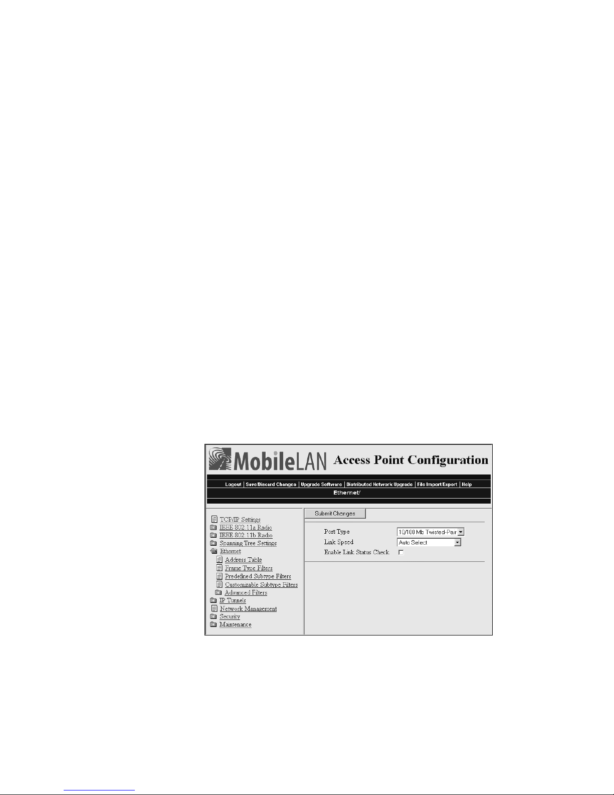
Chapter 3 — Configuring the Ethernet Network
Configuring Other Ethernet or Fiber Optic Settings
Many of the standard Ethernet or fiber optic settings are configured in the
TCP/IP Settings screen. For help, see “Configuring the TCP/IP Settings”
on page 60. In the Ethernet screen, you can:
• set the port type. This field specifies the port that the access point uses
to communicate with the Ethernet network. If you do not have a fiber
optic port, you will not see this field.
• set the link speed. This field specifies the speed and the duplex mode
that the access point uses to communicate with the Ethernet network. If
you chose the port type to be fiber optic, the link speed is automatically
set to 100 Mbps Fiber Optic (full duplex). If you want the access point
to auto-negotiate this field, choose Auto Select. Auto Select should work
for most networks.
• enable or disable the link status check. Check this check box if you want
the access point to periodically check its Ethernet connection. If it loses
the connection, this access point can no longer be the root access point
and any end devices that are connected to this access point (whether or
not it is the root) will roam to a different access point. The access point
will attempt to reconnect to the spanning tree through one of its radio
ports. Clear this check box if this access point must be the root access
point or if it is used as a WAP.
To configure the Ethernet or fiber optic settings
1 From the menu, click Ethernet. The Ethernet screen appears.
2 In the Port Type field, choose 10/100 Mb Twisted-Pair for Ethernet or
100 Mb Fiber Optic.
3 (10/100 Mb Twisted-Pair only) In the Link Speed field, choose the
speed and duplex mode you want this port to use to communicate with
the Ethernet or fiber optic network.
MobileLAN access System Manual 67
Page 82
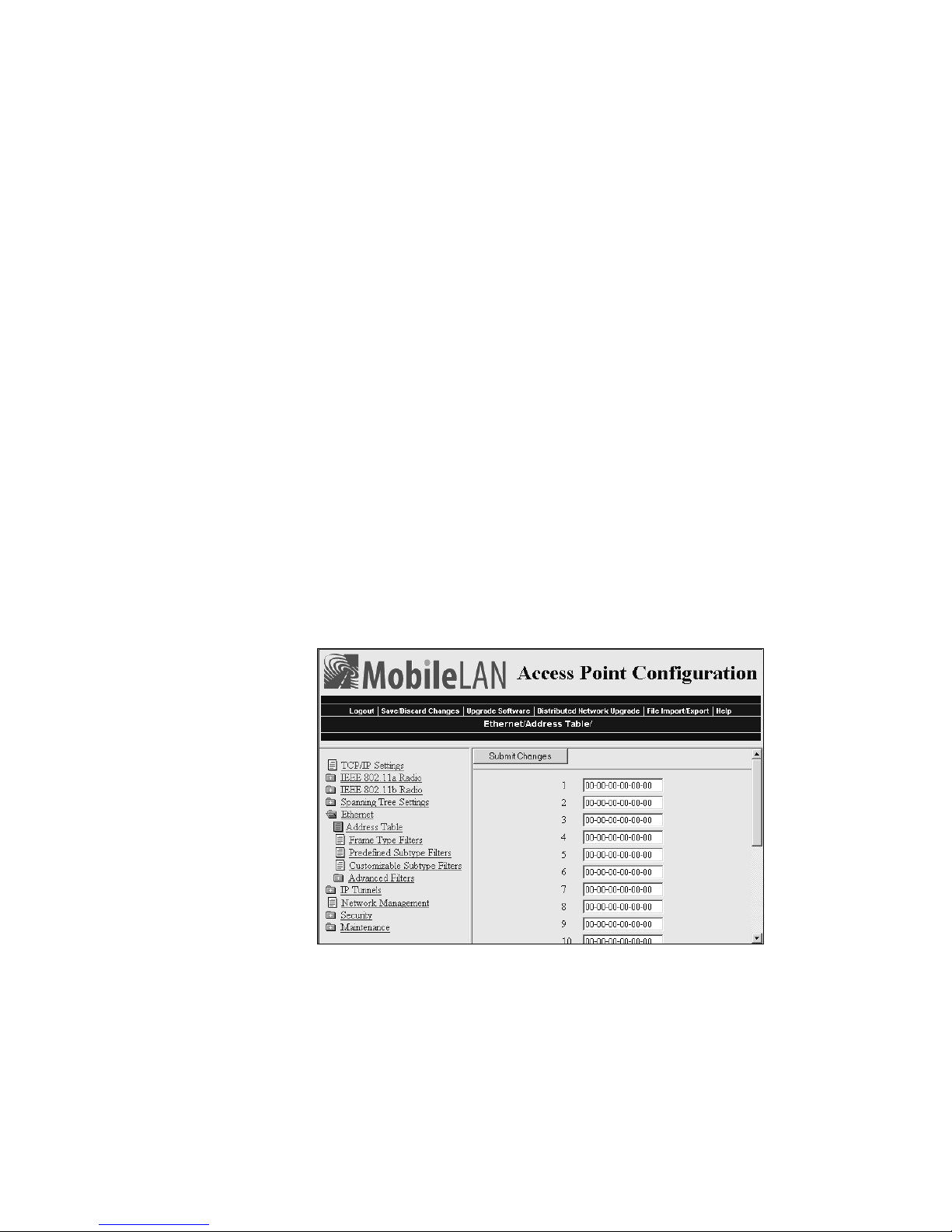
Chapter 3 — Configuring the Ethernet Network
4 Check or clear the Enable Link Status Check check box.
5 Click Submit Changes to save your changes. To activate your changes,
from the menu bar click Save/Discard Changes, and then click Save
Changes and Reboot. For help, see “Saving Configuration Changes”
on page 36.
Configuring the Ethernet Address Table
If you have a secondary LAN, you should configure the Ethernet address
table in the designated bridge or WAP on the secondary LAN. This table
contains all the MAC addresses on the secondary LAN that are
communicating with the primary LAN. You must enter the MAC
addresses of all devices on the secondary LAN that do not always initiate
communication.
If you choose not to configure this table, the designated bridge or WAP
may need to flood frames to the Ethernet and radio ports to learn the path
to the MAC address.
These addresses become permanent entries in the forwarding table of the
designated bridge or WAP.
To configure the Ethernet address table
1 From the main menu, click Ethernet, and then click Ethernet Filters.
2 Click Address Table. The Address Table screen appears.
3 Enter up to 20 MAC addresses. MAC addresses consist of six hex pairs
that are separated by spaces, colons, or hyphens.
4 Click Submit Changes to save your changes. To activate your changes,
from the menu bar click Save/Discard Changes, and then click Save
Changes and Reboot. For help, see “Saving Configuration Changes”
on page 36.
68 MobileLAN access System Manual
Page 83

Configuring Ethernet Filters
You can set both Ethernet and IP tunnel filters, and you can create
protocol filters for both predefined and user-defined protocol types. In
addition, you can define arbitrary frame filters based on frame content.
Setting Ethernet filters prevents the Ethernet port from sending out
unnecessary traffic to the wireless network.
Ethernet frame type filter and predefined subtype filter settings override
customizable subtype filter settings. However, Intermec recommends that
when creating customizable subtype filters, you do not duplicate existing
frame type or predefined subtype filters or unexpected results may occur.
For more examples of using Ethernet filters and for help configuring IP
filters, see “Configuring IP Tunnel Filters” in Chapter 5.
Using Ethernet Frame Type Filters
You can define filters for common networking protocols such as IP, Novell
IPX, and 802.2 LLC. You can also set filters that will pass only those
Ethernet frame types found on your network.
Chapter 3 — Configuring the Ethernet Network
You can set the default action for general and specific frame types. For
example, you can not pass the DIX-Other EtherTypes frame parameter,
and then use the subtype menus to pass only those specific DIX types that
are used in your radio network.
You can also set the scope for general and specific frame types. For
example, for DIX-IP-TCP ports, you can not pass all frame types. Then,
all IP frames with the TCP type will be dropped even if specific TCP parts
are set to pass in the subtype menus.
Here is the action and scope you can set for each parameter:
Allow/
Pass
Scope
Check or clear this check box. Check the check box to pass all frames of that
type. Clear the check box to drop all frames of that type.
Set scope to Unlisted or All. If you select All, then all frames of that type are
unconditionally passed or dropped, depending on the action you specified. If
you select Unlisted, then frames are passed or dropped only if the frame type
is not listed in the predefined or customizable tables.
MobileLAN access System Manual 69
Page 84
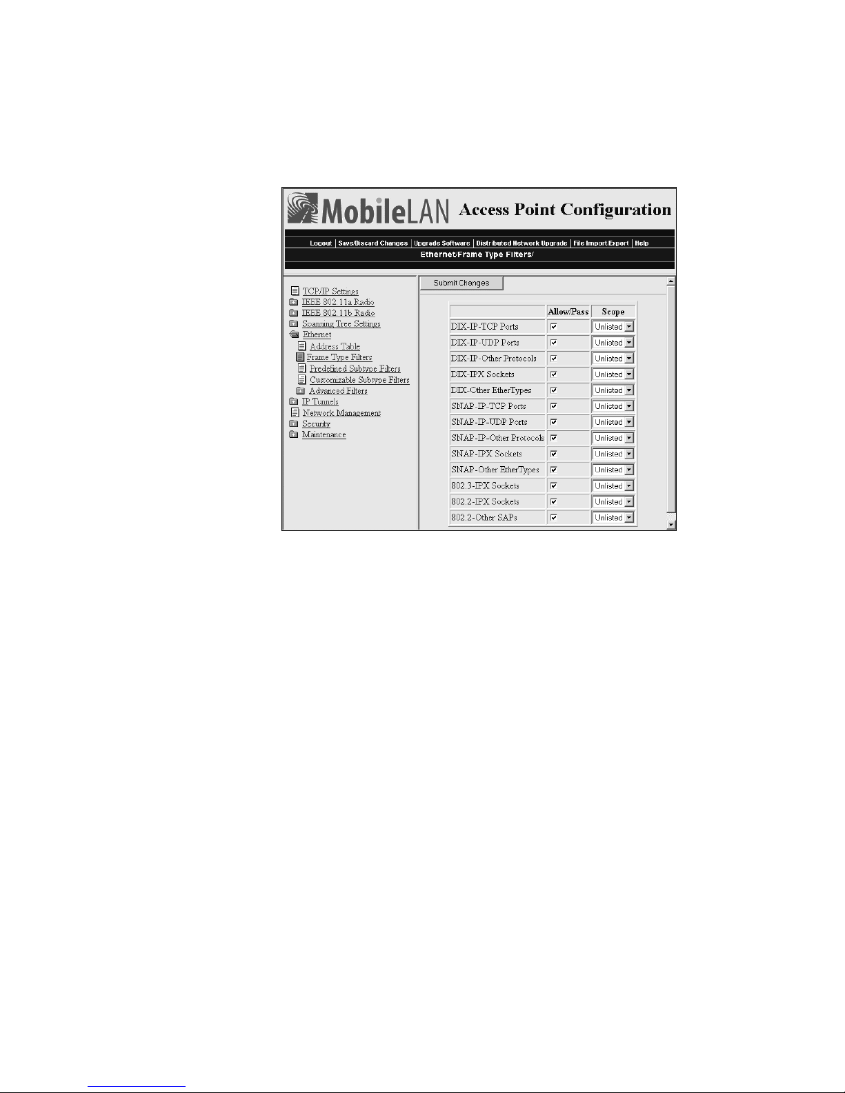
Chapter 3 — Configuring the Ethernet Network
To set frame type filters
1 From the main menu, click Ethernet > Frame Type Filters. The Frame
Type Filters screen appears.
2 For each frame type field, check or clear the check box to configure if
the frame types are passed or are dropped. If you check the check box,
the frame type is allowed to pass.
For each frame type field, set the Scope field to Unlisted or All.
For help, see the next table.
3 Click Submit Changes to save your changes. To activate your changes,
from the menu bar click Save/Discard Changes, and then click Save
Changes and Reboot. For help, see “Saving Configuration Changes”
on page 36.
4 If you set the Scope field to Unlisted for any of the frame types, you
must also configure predefined subtype filters or customizable subtype
filters. For help, see “Using Predefined Subtype Filters” on page 71 or
“Customizing Subtype Filters” on page 72.
70 MobileLAN access System Manual
Page 85
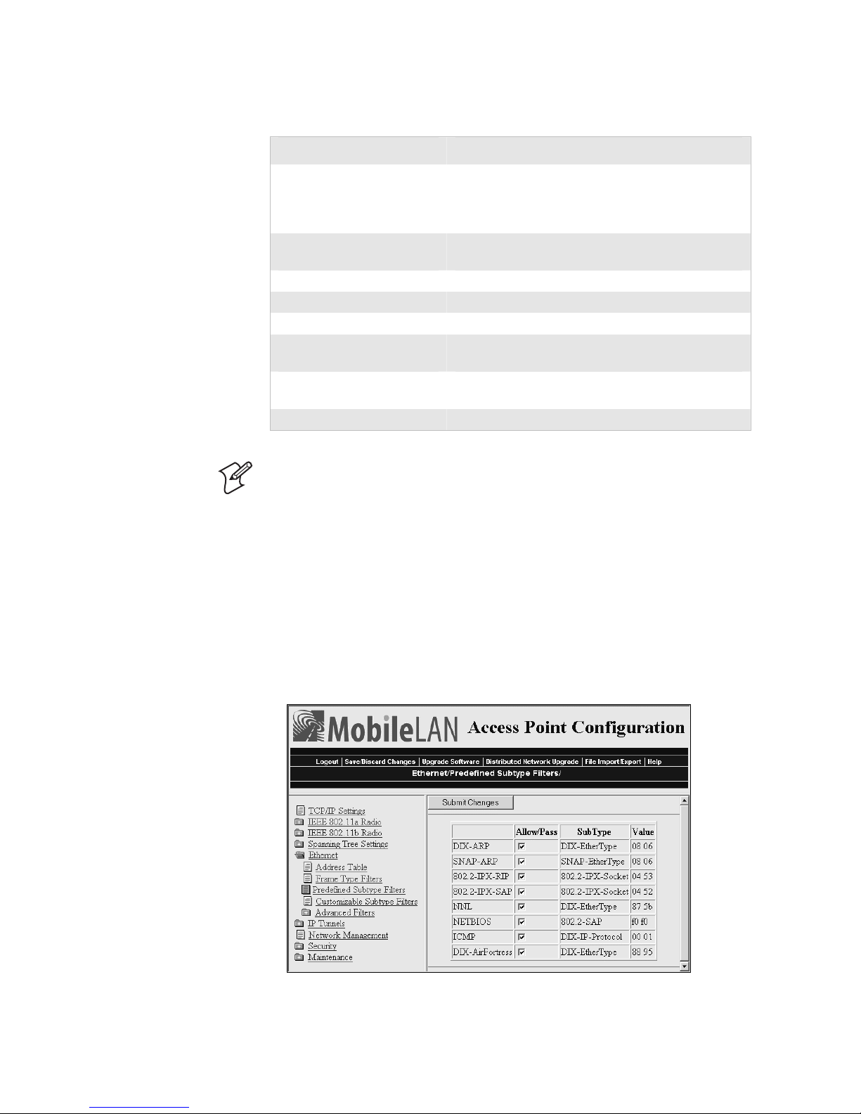
Chapter 3 — Configuring the Ethernet Network
Frame Type Filter Descriptions
Frame Type Explanation
DIX IP TCP Ports
DIX IP UDP Ports
SNAP IP TCP Ports
SNAP IP UDP Ports
DIX IP Other Protocols
SNAP IP Other Protocols
DIX IPX Sockets Novell NetWare protocol over Ethernet II frames.
SNAP IPX Sockets Novell NetWare protocol over 802.2 SNAP frames.
802.3 IPX Sockets Novell NetWare protocol over 802.3 RAW frames.
DIX Other Ethernet Types
SNAP Other Ethernet Types
802.2 IPX Sockets Novell running over 802.2 Logical Link Control
802.2 Other SAPs 802.2 SAPs other than IPX or SNAP.
Primary Internet Protocol Suite (IP) transport
protocols.
IP protocols other than TCP or User Datagram
Protocol (UDP).
DIX or SNAP registered protocols other than IP or
IPX.
(LLC).
Note: You should not filter HTTP, Telnet, SNMP, and ICMP frames if
you are using WAPs because these frame types are used for configuring,
troubleshooting, and upgrading WAPs.
Using Predefined Subtype Filters
You can configure the access point to pass or drop certain predefined
frame subtypes.
To configure predefined subtype filters
1 From the main menu, click Ethernet > Predefined Subtype Filters.
The Predefined Subtype Filters screen appears.
MobileLAN access System Manual 71
Page 86
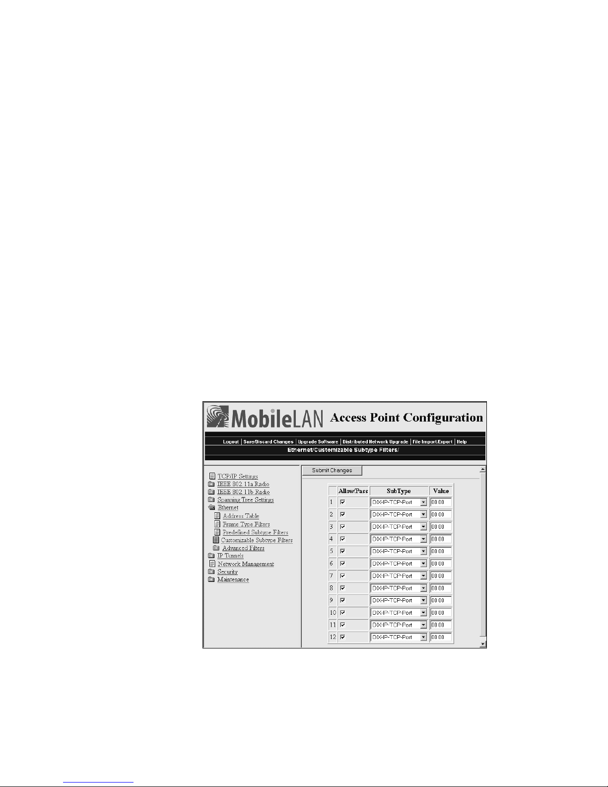
Chapter 3 — Configuring the Ethernet Network
2 For each frame subtype field, check or clear the check box to configure
if the frame subtypes are passed or are dropped. If you check the check
box, the frame subtype is allowed to pass.
3 Click Submit Changes to save your changes. To activate your changes,
from the menu bar click Save/Discard Changes, and then click Save
Changes and Reboot. For help, see “Saving Configuration Changes”
on page 36.
Customizing Subtype Filters
You can configure the access point to pass or drop certain customized
frame subtypes. You define the action, subtype, and value parameters.
Allow/
Pass
Subtype
Value
Check or clear this check box. Check this check box to pass all frames of the
subtype and value. Clear this check box to drop all frames of the subtype and
value.
Selects the frame subtype you wish to configure.
The following table describes frame subtypes and their values. The value
must be two hex pairs. When a match is found between frame subtype and
value, the specified action is taken.
To customize subtype filters
1 From the main menu, click Ethernet > Customizable Subtype Filters.
The Customizable Subtype Filters screen appears.
2 For each subtype field, check or clear the check box to configure if the
subtypes are passed or are dropped. If you check the check box, the
subtype is allowed to pass.
72 MobileLAN access System Manual
Page 87

Chapter 3 — Configuring the Ethernet Network
3 In the SubType field, choose the customizable frame subtype. For help,
see the next table.
4 In the Value field, enter the two hex pairs. For help, see the next table.
5 Click Submit Changes to save your changes. To activate your changes,
from the menu bar click Save/Discard Changes, and then click Save
Changes and Reboot. For help, see “Saving Configuration Changes”
on page 36.
Subtype Filter Descriptions
Subtype Value
DIX-IP-TCP-Port Port value in hexadecimal.
DIX-IP-UDP-Port Port value in hexadecimal.
DIX-IP-Protocol Protocol number in hexadecimal.
DIX-IPX-Socket Socket value in hexadecimal.
DIX-EtherType Specify the registered DIX type in hexadecimal.
SNAP-IP-TCP-Port Port value in hexadecimal.
SNAP-IP-UDP-Port Port value in hexadecimal.
SNAP-IP-Protocol Port value in hexadecimal.
SNAP-IPX-Socket Socket value in hexadecimal.
SNAP-EtherType SNAP type in hexadecimal. To filter on both SNAP type and
OUI, use advanced filters.
802.3-IPX-Socket Socket value in hexadecimal.
802.2-IPX-Socket Socket value in hexadecimal.
802.2-SAP 802.2 SAP in hexadecimal.
Example
This example shows you how to use customizable filters to only allow the
wireless end devices (DHCP clients) that are communicating with the
access point (DHCP server) to receive TCP/IP settings. This example
prevents the wireless end devices from receiving TCP/IP settings from
another DHCP server on the Ethernet network. It also prevents the access
point from providing TCP/IP settings to DHCP clients on the wired
network.
MobileLAN access System Manual 73
Page 88
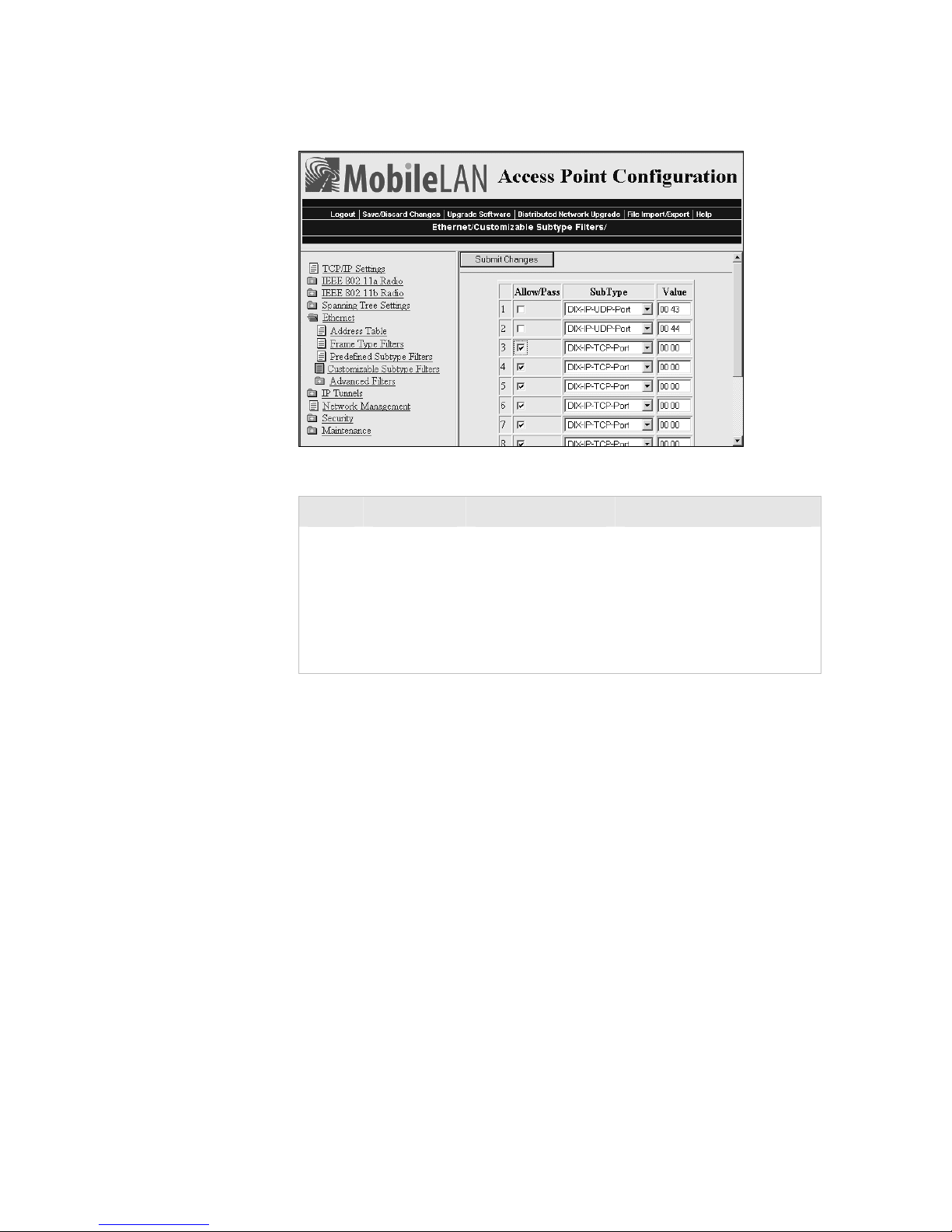
Chapter 3 — Configuring the Ethernet Network
For this example, set these customizable subtype filters.
Example – Customizable Subtype Filter
Filter Parameter Value Explanation
1 Allow/Pass Clear (drop)
Subtype DIX-IP-UDP-Port
Value 00 43
2 Allow/Pass Clear (drop)
Subtype DIX-IP-UDP-Port
Value 00 44
This filter drops DHCP
responses to wireless end
devices communicating with
this access point.
This filter drops DHCP
requests from DHCP clients
on the Ethernet network.
Configuring Advanced Filters
You can configure advanced filters if you need more flexibility in your
filtering. Settings for advanced filters execute after those for other filters;
that is, advanced filters are only applied if the frame has passed the other
filters.
You can use filter values and filter expressions to minimize network traffic
over the wireless links; however, Intermec recommends that you use
advanced Ethernet filters only if you have an extensive understanding of
network frames and their contents. Use other existing filters whenever
possible.
Setting Filter Values
You can associate an ID with a pattern value by selecting a filter, and then
entering an ID and a value. All values with the same value ID belong to
the same list.
74 MobileLAN access System Manual
Page 89
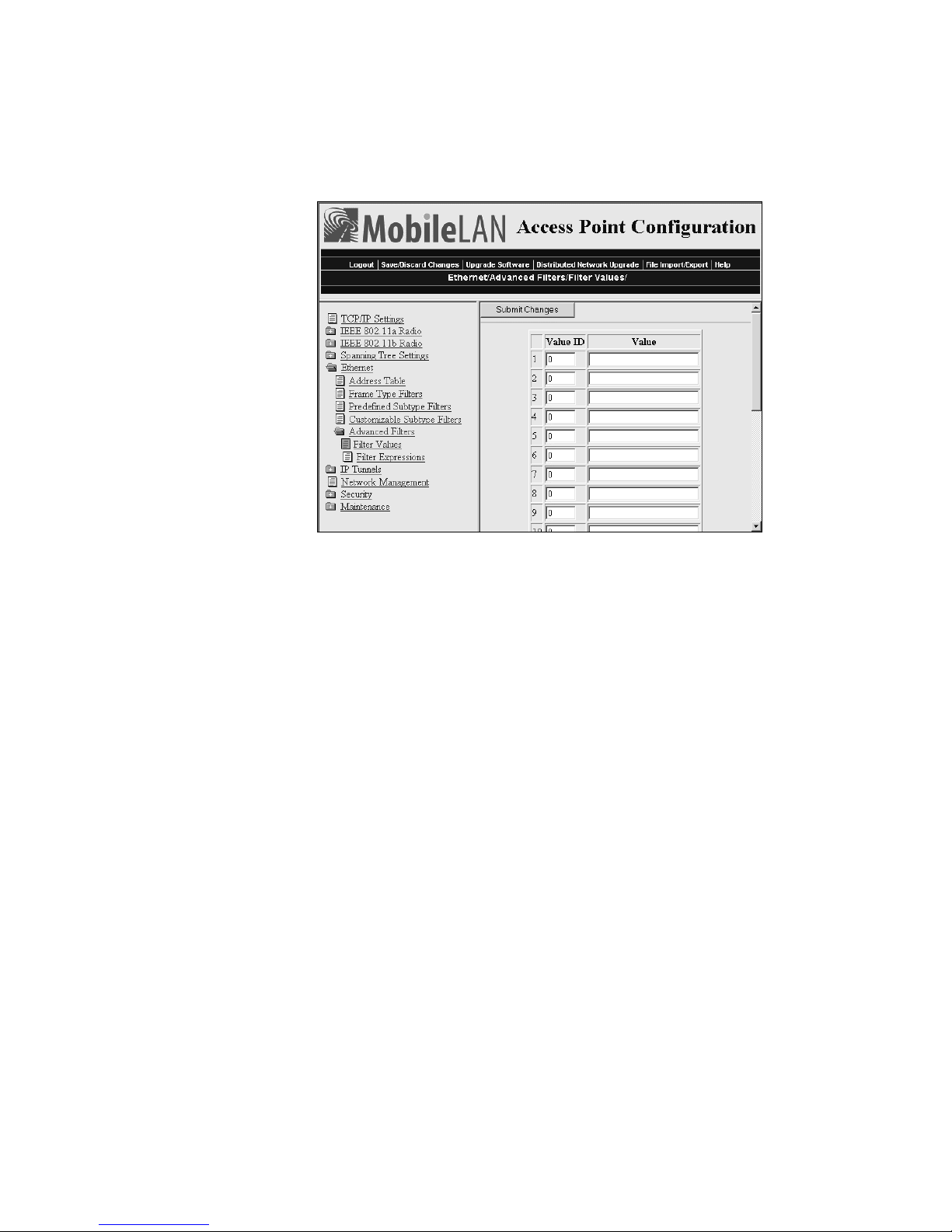
Chapter 3 — Configuring the Ethernet Network
To set the value ID and value
1 From the main menu, click Ethernet > Advanced Filters. The Filter
Values screen appears.
2 Enter up to 22 value IDs and values.
3 Click Submit Changes to save your changes. To activate your changes,
from the menu bar click Save/Discard Changes, and then click Save
Changes and Reboot. For help, see “Saving Configuration Changes”
on page 36.
Setting Filter Expressions
You can set filter expressions by specifying parameters for frame filters.
You can also create a filter expression, which is executed in ascending order
based on the ExprSeq values until the access point determines whether to
pass or drop the frame.
To set filter expressions
1 From the main menu, click Ethernet > Advanced Filters.
2 Click Filter Expressions. The Filter Expressions screen appears.
MobileLAN access System Manual 75
Page 90
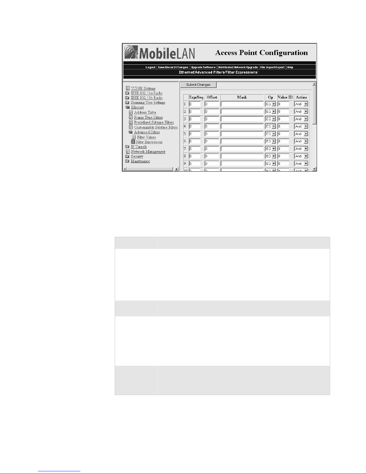
Chapter 3 — Configuring the Ethernet Network
3 Configure the filter expressions parameters. For help, see the next table.
4 Click Submit Changes to save your changes. To activate your changes,
from the menu bar click Save/Discard Changes, and then click Save
Changes and Reboot. For help, see “Saving Configuration Changes”
on page 36.
Filter Expressions Parameter Descriptions
Parameter Explanation
ExprSeq
(Expression
Sequence)
Offset Identifies a point inside the frame where testing for the expression is to
Mask Applies a data pattern to the frame. If the data pattern in the mask
Op
(Operation)
Indicates the order in which the filters will be executed. When you
change the parameter, the statements are reordered and renumbered so
the Expression Sequence order is maintained. The range is from 0 to
255.
This parameter works with the Action parameter; for example, if the
action is set to And, then the next sequence in another expression is
processed.
start. The range is from 0 to 65535.
matches the frame, then the specific action is performed. The mask
indicates the bits that are significant at the specified offset. A bit is
significant if a bit in the mask is set to one. If this field is empty, the
length of the field is determined by the longest value in the Filter
Values menu for the specified value ID. The mask values are entered in
hexadecimal pairs. You can enter 0 to 8 pairs.
Performs a logical operation when a data pattern matches a value in the
Filter Values menu to determine if the specified action should be
taken. Valid operations include: EQ (equal), NE (not equal), GT
(greater than), LT (less than or equal)
76 MobileLAN access System Manual
Page 91
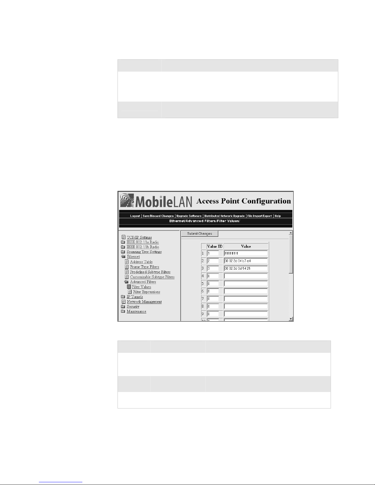
Chapter 3 — Configuring the Ethernet Network
Filter Expressions Parameter Descriptions (continued)
Parameter Explanation
Value ID Represents a value in the Filter Values menu. The bytes after the frame
offset are compared to the data pattern indicated by the value. Value
ID can be from 0 to 255 and must match one or more value IDs in the
Filter Values menu.
Action Sets the action to Pass, Drop, or And. If you set the action to And, the
filter expression with the next highest sequence is applied.
Example 1
This example shows you how to use Ethernet filters to filter all traffic that
passes through the access point to the wireless network except for traffic
for specified MAC addresses. These filters do not prevent wireless traffic
from reaching the Ethernet network. For this example, set these filter
values.
Example 1 - Filter Values
Value ID Value Description
1 ff ff ff ff ff ff Allows multicast traffic to enter the wireless
2 00 02 2d 04 b7 a4 The MAC address of an end device you want to
3 00 02 2d 0d 54 25 The MAC address of an end device you want to
MobileLAN access System Manual 77
network, which is necessary for IP end devices to
communicate
be able to communicate.
be able to communicate.
Page 92
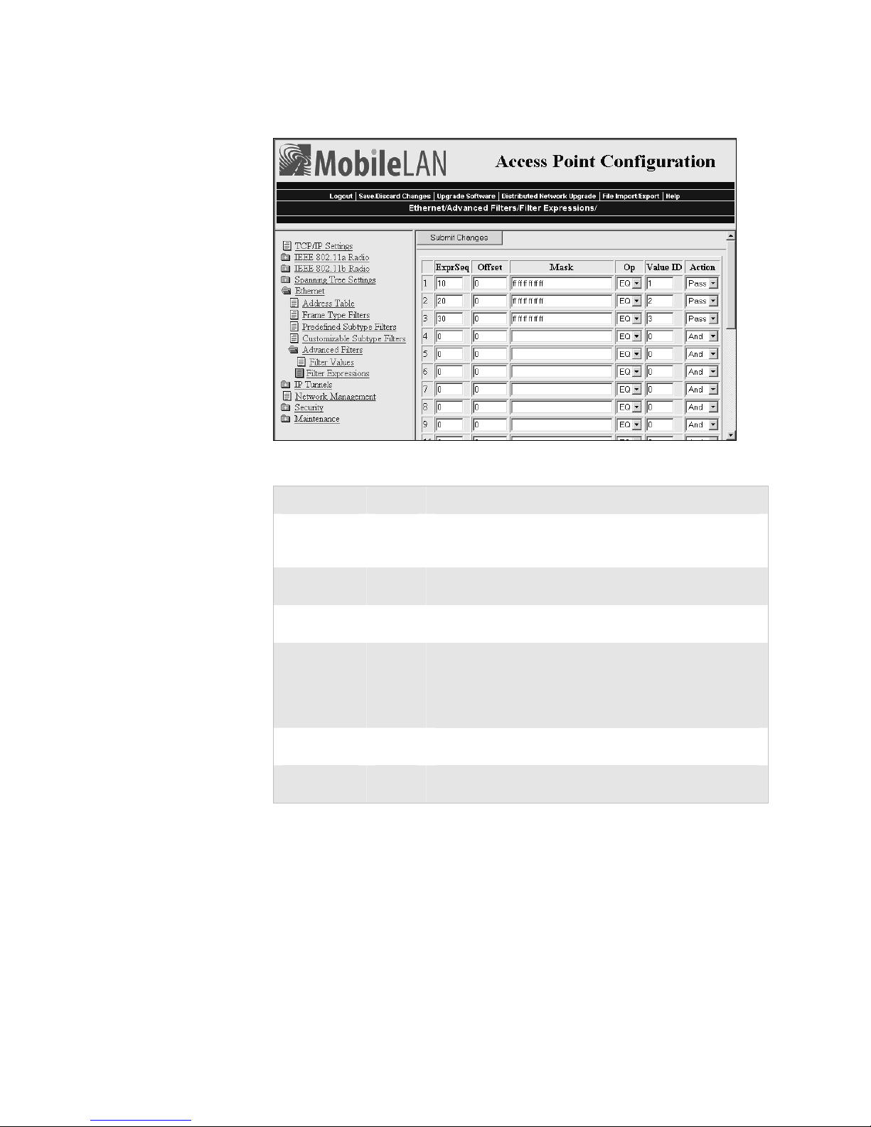
Chapter 3 — Configuring the Ethernet Network
For this example, set these filter expressions.
Example 1 –Filter Expressions
Parameter Value Explanation
ExprSeq 10 The order that you want the expressions executed. You
must have an expression for each Value ID that is listed in
the Filter Values menu.
Offset 0 Since the filter is applied to the destination address, which
is the first value in the frame, the offset is 0.
Mask ff ff ff
ff ff ff
Op EQ Compares the value after the offset and mask are applied
Value ID 1 This filter expression applies to value ID 1 from the Filter
Action Pass If this filter expression is true, continue to the next
Compares the entire 6-byte destination address for an
exact match.
to the value of the Value ID from the Filter Values menu
to see if they are equal. (If the value at the offset equals the
specified value on the Filter Values menu, the frame is
multicast.)
Values menu.
expression.
You must enter a filter expression for each Value ID in the Filter Values
menu. In this example, only the ExprSeq value and the Value ID value
change.
78 MobileLAN access System Manual
Page 93
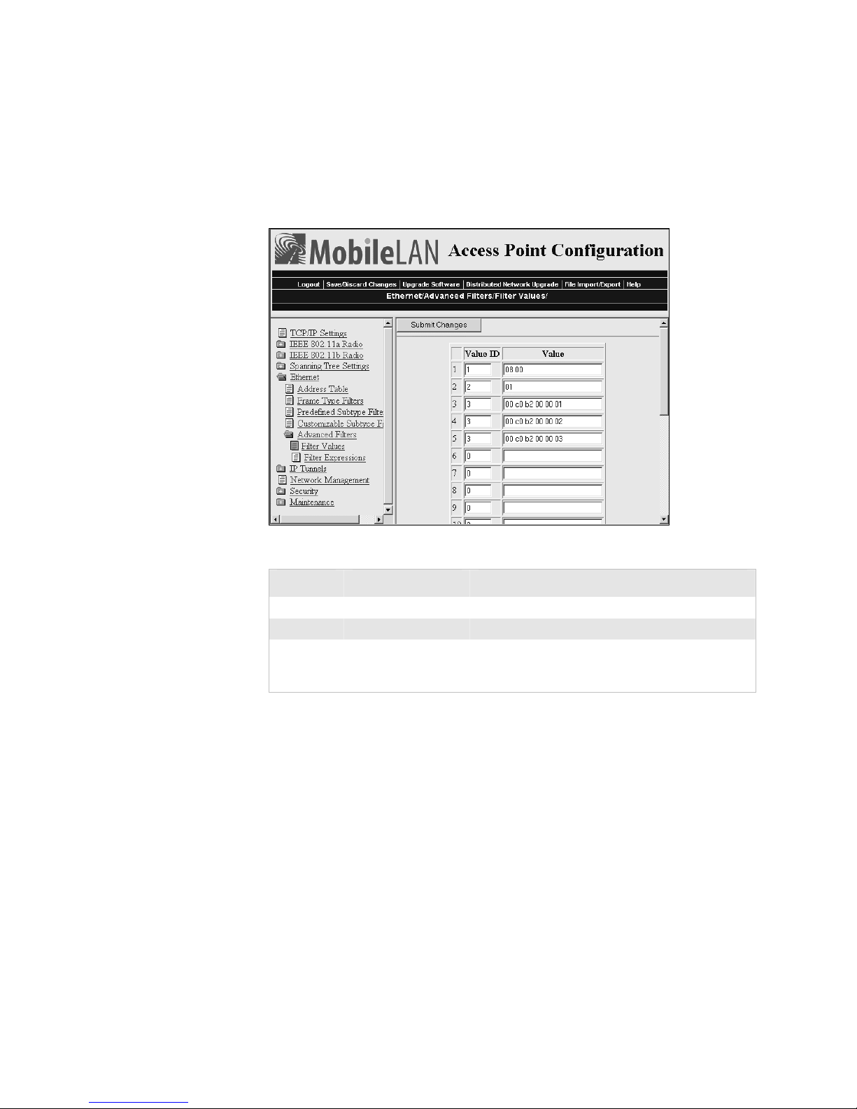
Chapter 3 — Configuring the Ethernet Network
Example 2
This example shows how to use Ethernet filters to discard all DIX IP
multicast frames except those from selected devices. Three entries have a
value ID of 3 to demonstrate how to enter a list. All entries with the same
value ID belong to the same list. For this example, set these filter values.
Example 2 - Filter Values
Value ID Value Description
1 08 00 Check for a DIX IP frame.
2 01 Check for a multicast frame.
3 00 c0 b2 00 00 01
00 c0 b2 00 00 02
00 c0 b2 00 00 03
Check for these specific MAC device addresses.
You must enter a filter expression for each Value ID in the Filter Values
menu. In this example, three expressions combine to form a single
compound expression. The compound expression forms an advanced filter
that drops all DIX IP multicast frames except those from the three
Ethernet stations whose addresses are listed on the Filter Values menu.
The default action is the opposite of the action specified in the last
expression. In this example, the action of the last expression is drop;
therefore, the default action is pass. Any frame that meets the conditions
specified in the advanced filter is passed.
MobileLAN access System Manual 79
Page 94
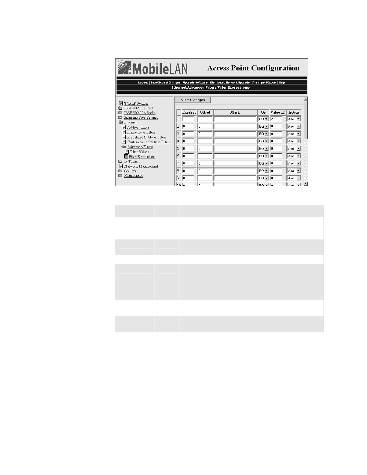
Chapter 3 — Configuring the Ethernet Network
Set the first filter expression as shown below.
Example 2 – First Filter Expression
Parameter Value Explanation
ExprSeq 1 The first expression that is executed. You must have an
expression for each Value ID that is listed in the Filter
Values menu.
Offset 0 Since the filter is applied to the destination address, which
is the first value in the frame, the offset is 0.
Mask 01 Checks only the Ethernet multicast bit.
Op EQ Compares the value after the offset and mask are applied
to the value of the Value ID from the Filter Values menu
to see if they are equal. (If the value at the offset equals the
specified value on the Filter Values menu, the frame is
multicast.)
Value ID 2 This filter expression applies to value ID 2 from the Filter
Values menu.
Action And If this filter expression is true, continue to the next
expression.
80 MobileLAN access System Manual
Page 95
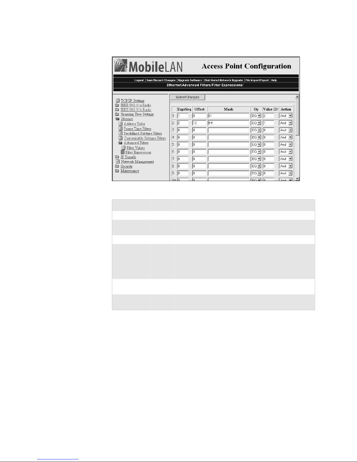
Chapter 3 — Configuring the Ethernet Network
Set the second filter expression as shown below.
Example 2 – Second Filter Expression
Parameter Value Explanation
ExprSeq 2 The second expression that is executed.
Offset 12 Checks for the DIX IP frame type, which starts 12 bytes
from the destination address.
Mask ff ff Checks the 2-byte DIX IP frame type for an exact match.
Op EQ Compares the value after the offset and mask are applied
to the value of the Value ID from the Filter Values menu
to see if they are equal. (If the value at the offset equals the
specified value on the Filter Values menu, the frame is
DIX IP.)
Value ID 1 This filter expression applies to value ID 1 from the Filter
Values menu.
Action And If this filter expression is true, continue to the next
expression.
MobileLAN access System Manual 81
Page 96
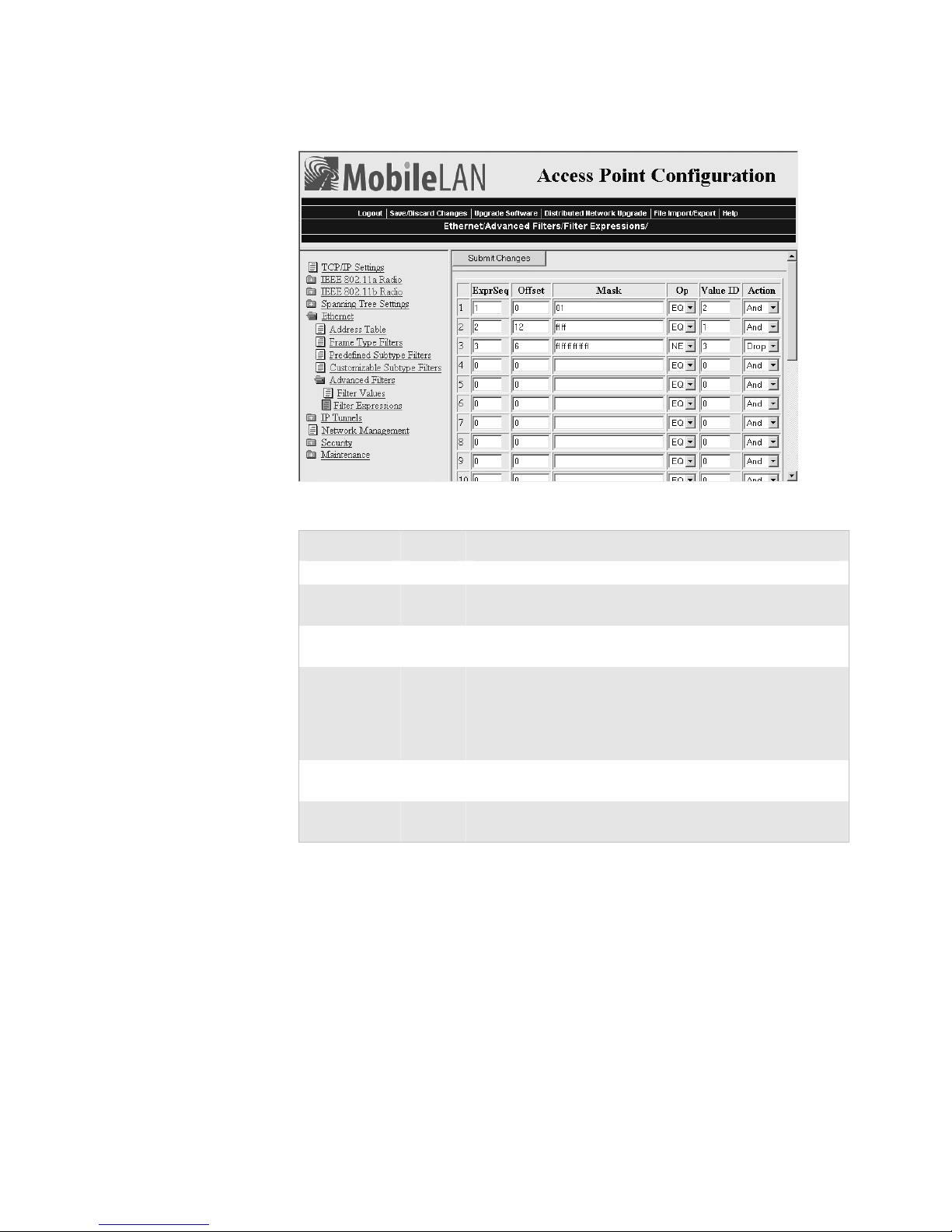
Chapter 3 — Configuring the Ethernet Network
Set the third filter expression as shown below.
Example 2 – Third Filter Expression
Parameter Value Explanation
ExprSeq 3 The third expression that is executed.
Offset 6 Checks the source Ethernet address, which starts 6 bytes
from the destination address.
Mask ff ff ff
ff ff ff
OP NE Compares the value after the offset and mask are applied to
Value ID 3 This filter expression applies to value ID 3 from the Filter
Action Drop If the source Ethernet address does not match any address in
Checks the 6-byte source Ethernet address for an exact
match.
the value of the Value ID from the Filter Values menu to
see if they are not equal. (Compare the source Ethernet
address with the list of MAC addresses from the Filter
Values menu.)
Values menu.
the list on the Filter Values menu, then drop the frame.
82 MobileLAN access System Manual
Page 97

Configuring the Radios
4
This chapter explains how to configure the radios in the MobileLAN
access products so that they communicate with your wireless end devices.
This chapter covers these topics:
• Configuring the IEEE 802.11b radio
• Configuring the IEEE 802.11a radio
• Configuring the WLI Forum OpenAir radio
• Configuring the 902 MHz radio
MobileLAN access System Manual 83
Page 98

Chapter 4 — Configuring the Radios
About the Radios
MobileLAN access products may contain one or two radios. You can use
access points that contain two different types of radios to support two
different types of wireless networks, such as legacy networks. You can use
access points with two of the same type of radios as WAPs, as point-tomultipoint bridges, to increase throughput in a busy network, or to
provide redundancy.
Access Point Radios Supported and Features
Access Point Radios Supported
WA22 802.11b, 802.11a Yes Yes
2101 802.11b, OpenAir Yes Yes
WA21 802.11b, 802.11a Yes Yes
2100 802.11b, OpenAir
902 MHz
2102 802.11b, OpenAir No Yes
2106 802.11a No No
Dual Radio
Support
Yes Yes
Radio
Independent
The next sections explain how to configure the radios that are in your
access point. If the radio is not installed in your access point, then you will
not see it listed in the main menu.
84 MobileLAN access System Manual
Page 99
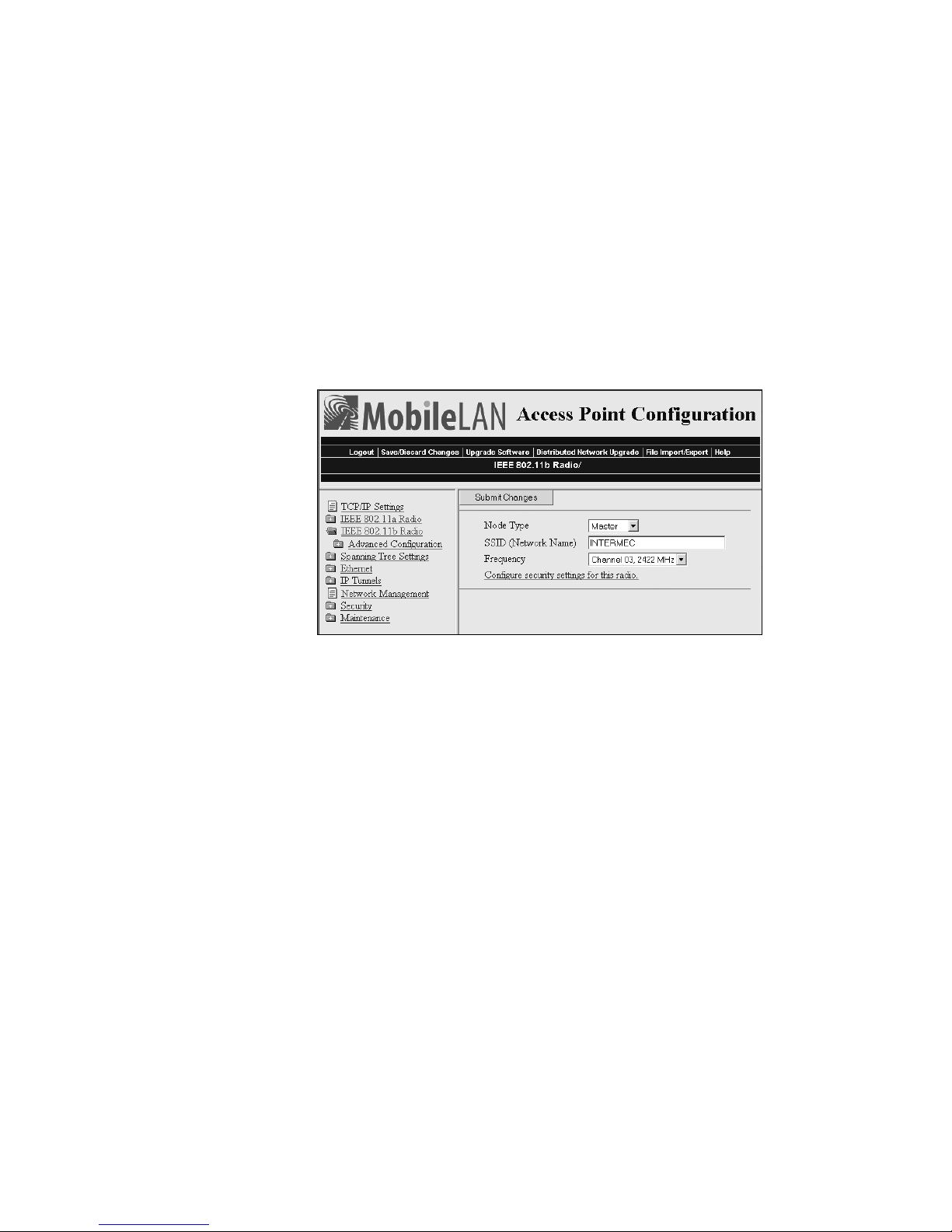
Configuring the IEEE 802.11b Radio
The IEEE 802.11b radio will communicate with other 802.11b radios that
have the same:
• SSID (Network Name)
• Security
To configure the 802.11b radio
1 From the main menu, click IEEE 802.11b Radio. The IEEE 802.11b
Radio screen appears.
Chapter 4 — Configuring the Radios
2 Configure the parameters for the radio. For help, see the next table.
3 Configure the advanced parameters for the radio. For help, see
“Configuring 802.11b Radio Advanced Parameters” on page 87.
4 (Master only) Configure inbound filters. For help, see “Configuring
802.11b Radio Inbound Filters” on page 89.
5 Click Submit Changes to save your changes. To activate your changes,
from the menu bar click Save/Discard Changes, and then click Save
Changes and Reboot. For help, see “Saving Configuration Changes”
on page 36.
6 (Optional) Configure security by clicking Configure security settings
for this radio. For help, see Chapter 6, “Configuring Security.”
MobileLAN access System Manual 85
Page 100

Chapter 4 — Configuring the Radios
802.11b Radio Parameter Descriptions
Parameter Explanation
Node Type Configure the 802.11b radio as a master or station. You can also
SSID
(Network Name)
Frequency
(Master radio only)
disable the radio.
Enter the network name for this access point. 802.11b radios
communicate with other 802.11b radios with the same network
name. You need to assign the same network name to the wireless
end devices that will connect to the access point.
The network name is case sensitive and can be no more than 32
alphanumeric characters.
Choose the frequency within the 2.4 to 2.5 GHz range that this
access point uses to transmit and receive frames. The available
frequencies are country-dependent and are determined by the
radio. See the “Worldwide Frequencies for the 802.11b Radio”
table.
Configure all access points used in Spain, France, or Japan to a
common frequency. For all other countries, configure all access
points to a common frequency, or select up to three frequencies
that are at least three channels (or 25 MHz) apart. For example,
you could select 2412 MHz, 2437 MHz, and 2462 MHz. You
may want to use a single frequency to isolate the installation to
part of the band; for example, use a single frequency if other
wireless networks or microwave ovens are in the area.
For optimal performance of master radios in access points that
are in range of each other, configure the frequencies to be at least
five channels apart. For example, configure the frequency to use
channels 1, 6, and 11.
Worldwide Frequencies for the 802.11b Radio
Channel FCC ETSI France Japan Israel
1 2412 2412 2412
2 2417 2417 2417
3 2422
(default)
4 2427 2427 2427
5 2432 2432 2432
6 2437 2437 2437
7 2442 2442 2442
8 2447 2447 2447
9 2452 2452 2452
10 2457 2457 2457 2457
11 2462 2462 2462
12 2467 2467 2467
13 2472 2472 2472
14 2484
2422
(default)
2422
(default)
2462
(default)
2422
(default)
86 MobileLAN access System Manual
 Loading...