

Page 1
Installation
Instructions
IV6
Portable Reader
Power Cable Kit
Page 2

Power Cable Kit (p/n: 203-714-001)
Packing List
Ensure you have received these items:
S IV6 Power Cable Kit Installation Instructions
S 17-Position cable assembly (p/n: 236-040-001)
S Fuse holder
S 5 Amp./250 volt fast acting fuse
S 3/8” heat shrink tubing (6 inches)
S 1/4” heat shrink tubing (6 inches)
S Cable ties (6)
S Adjustable cable clip
S 2-Pin circular connector
2 IV6 Portable Reader Power Cable Kit
Page 3
Instructions
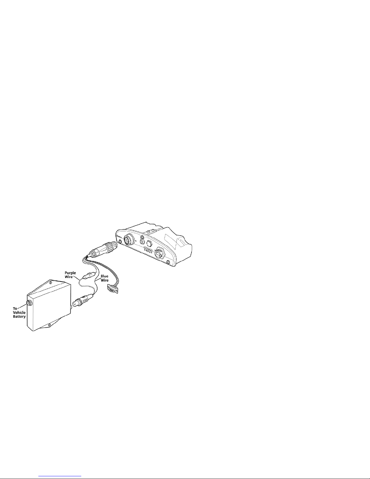
1 Cut back the cable assembly jacket about 18 inches.
2 Cut the purple wire and solder in the fuse holder. Install the
5 amp. fuse into the holder.
3 Attach heat shrink tubing to the connections on the fuse
holder. Use a heat gun to seal the heat shrink tubing.
4 Usethetiewrapsonthecableassemblywires.Attachthe
cord clip to an appropriate location to ensure the cables are
not obstructing the user’s operation of the equipment.
5 Attach the purple wire and blue wire to the 2-pin connector.
Attach heat shrink tubing where the connector and wire assembly meet. Use a heat gun to seal the heat shrink tubing.
6 Connect the 2-pin connector to the Intermec power supply
(p/n: 851-041-002). Connect the circular data connector to
the Reader.
7 The remaining wires on the cable are data lines (RS-232) and
general purpose input/output lines. Refer to the GPIO Pin
Function/Assignment Table in the IV6 Portable Reader
Quick Start Guide (p/n: 962-054-119) for details.
8 Connectthecablefromthepowersupplytothevehiclepow-
er source.
IV6 Portable Reader Power Cable Kit
3
Page 4

Corporate Headquarters
6001 36th Avenue West
Everett, Washington 98203
U.S.A.
tel 425.348.2600
fax 425.355.9551
www.intermec.com
IV6 Power Cable Kit Installation Instructions
*962-054-127A*
P/N 962-054-127A
e 2005 by Intermec Technologies Corporation. All rights reserved.
 Loading...