

Page 1

User's Manual
P/N 067296-005
DCS 300
Page 2

Intermec Technologies Corporation
6001 36th Avenue West
P.O. Box 4280
Everett, WA 98203-9280
U.S. service and technical support: 1-800-755-5505
U.S. media supplies ordering information: 1-800-227-9947
Canadian service and technical support: 1-800-668-7043
Canadian media supplies ordering information: 1-800-268-6936
Outside U.S. and Canada: Contact your local Intermec service supplier.
The information contained herein is proprietary and is provided solely for the purpose of allowing customers
to operate and/or service Intermec manufactured equipment and is not to be released, reproduced, or used for
any other purpose without written permission of Intermec.
Information and specifications in this manual are subject to change without notice.
2001 by Intermec Technologies Corporation
All Rights Reserved
The word Intermec, the Intermec logo, INCA (under license), MobileLAN, JANUS, IRL, Trakker Antares,
EZBuilder, TE 2000, Data Collection Browser, dcBrowser, Universal Access Point, UAP, Duratherm,
EasyCoder, Precision Print, PrintSet, Virtual Wedge, and CrossBar are either trademarks or registered
trademarks of Intermec.
Throughout this manual, trademarked names may be used. Rather than put a trademark ( or ) symbol in
every occurrence of a trademarked name, we state that we are using the names only in an editorial fashion, and
to the benefit of the trademark owner, with no intention of infringement.
Page 3

DCS 300 User’s Manual
Manual Change Record
This page records changes that have been made to this manual. This manual was
originally released at version 001.
Version Date Description
002 11/98 Added information on using WTP devices with the DCS 300.
Removed information on the terminal template application in
Chapter 11, “Using Screen Mapping.” Rearranged the chapters.
Made other minor corrections throughout the entire manual.
003 3/99 Added addendum 069283-001 that documents the v1.2
software. Includes information on using WTP devices that
communicate in Norand Native mode. Also documents using
TN3270/TN5250 terminal sessions.
004 9/99 Modified addendum to document v1.3 software. Includes
information on the Data Collection Browser (dcBrowser).
Removed Fast Setup Quick Reference Guide.
005 10/01 Incorporated addendum 069283-002. Added Data Collection
Browser information. Added new information to support v1.6
software. Includes information about the new Web browser
interface, DDNS, DHCP, SNMP, and IDRS.
Page 4

DCS 300 User’s Manual
blank
Page 5

Contents
Contents
Before You Begin xvii
Warranty Information xvii
Safety Summary xvii
Warnings, Cautions, and Notes xviii
About This Manual xix
Other Intermec Manuals xxi
Getting Started
1
Chapter Checklist 1-3
Features 1-4
Unpacking the DCS 300 1-5
Description 1-6
Understanding the Front Panel 1-6
Understanding the Rear Panel 1-7
Plugging In the Power Cord 1-8
Connecting an Uninterruptable Power Supply 1-9
Plugging In the Keyboard 1-11
Connecting the Monitor 1-12
Connecting a Modem 1-13
Mounting the DCS 300 in a Rack 1-15
Turning the DCS 300 On and Off 1-16
Turning On the DCS 300 1-17
Turning Off the DCS 300 1-18
Learning About the DCS 300
2
Chapter Checklist 2-3
About the DCS 300 Local Interface 2-4
Getting Help 2-6
Navigating Through Dialog Boxes 2-7
Understanding the Dialog Box Buttons 2-8
v
Page 6

DCS 300 User’s Manual
CODE39
About the Web Browser Interface 2-9
Setting the Date and Time 2-12
Setting the System Parameters 2-14
About the Configuration Files 2-16
Backing Up the DCS 300 Configuration 2-17
Restoring the DCS 300 Configuration 2-19
Deleting User Files 2-22
Opening the DCS 300 Home Page 2-9
Getting Help 2-11
Restoring the Default Configuration 2-16
Backing Up Your System Files and Runtime Configuration 2-17
Backing Up Your User Files 2-18
Restoring Your System Files and Runtime Configuration 2-19
Restoring Your User Files 2-20
3
Starting and Stopping the Downline Network 2-23
Starting Data Collection 2-23
Stopping Data Collection 2-24
Accessing a Command Prompt 2-25
Connecting to the Upline Network
Chapter Checklist 3-3
Connecting to an Ethernet Network 3-4
Installing the DCS 300 3-4
Configuring the Ethernet Card for TCP/IP 3-5
Using DNS 3-7
Clearing the IP Address and Subnet Mask 3-9
Configuring the Ethernet Card for IEEE 802.2 3-9
Connecting to a Token Ring Network 3-11
Installing the DCS 300 3-11
Configuring the Token Ring Card for TCP/IP 3-11
Using DNS 3-14
Configuring the Token Ring Card for IEEE 802.2 3-15
vi
Page 7

Connecting to a Twinaxial Network 3-17
Installing the DCS 300 3-17
Configuring the Twinaxial Card 3-17
Connecting to an SDLC Network 3-18
Installing the DCS 300 3-18
Configuring the SDLC Card 3-19
Configuring Advanced SDLC Parameters 3-20
Configuring IP Routes 3-21
Using the Routing Daemon 3-21
Configuring Routing Tables 3-22
Using the Auto Fallback Feature 3-23
Configuring the DCS 300s 3-24
Configuring the Trakker Antares UDP Plus Terminals 3-24
Configuring the WTP Devices 3-24
Saving Your Runtime Configuration 3-25
Contents
4
Connecting to the Intermec RF Network
Chapter Checklist 4-3
Connecting the DCS 300 to the 900 MHz RF Network 4-4
Configuring the RF Card 4-6
Adding an RF Card 4-8
Setting the Time Parameters 4-10
Defining Default Hosts 4-12
Defining the RF Card Devices 4-13
Enabling the RF Card Devices 4-14
Editing an RF Card Device 4-15
Connecting the DCS 300 to the UDP Plus Network 4-17
Configuring a UDP Plus Network 4-18
Adding a UDP Plus Network 4-19
Setting the Time Parameters 4-21
Defining Default Hosts 4-23
Setting Up the UDP Plus Devices 4-24
Enabling the UDP Plus Devices 4-25
Editing a UDP Plus Device 4-27
Determining a UDP Plus Device’s IP Address 4-28
Editing a UDP Plus Device’s IP Address 4-29
vii
Page 8

DCS 300 User’s Manual
CODE39
Connecting the DCS 300 to the WTP Network 4-30
Saving Your Runtime Configuration 4-39
Connecting to the 9180 and the Intermec CrossBar
Configuring a WTP Network 4-31
Adding a WTP Network 4-32
Setting Up the WTP Devices 4-34
About the RF Hosts Created for the WTP Network 4-35
Editing the WTP Network 4-36
Enabling the WTP Devices 4-37
Editing a WTP Device 4-38
5
6
Network
Chapter Checklist 5-3
Configuring an Intermec Controller 5-4
About the Controller Parameters 5-6
Adding a 9154 Controller 5-6
Adding a 9161 Controller 5-9
Adding a 9180 v1.x Controller 5-11
Adding a 9180 v2.0 Controller 5-13
Setting the Time Parameters 5-15
Defining Default Hosts (9180 v2.0) 5-18
Defining the 9180 v2.0 Devices 5-19
Identifying the CrossBar Devices 5-20
Editing a CrossBar Device 5-22
Saving Your Runtime Configuration 5-23
Running Data Collection Browser
Chapter Checklist 6-3
About the Data Collection Browser 6-4
About the Environments 6-6
Setting Up the Runtime Environment 6-7
Running Your HTML Application 6-8
Starting the dcBrowser Gateway 6-8
Mapping dcBrowser Devices 6-9
Starting the Web Server 6-12
viii
Page 9

Running Terminal Emulation
Contents
7
Chapter Checklist 7-3
About Terminal Emulation 7-4
JANUS TE Applications 7-6
Trakker Antares TE Applications 7-6
WTP TE Applications 7-6
Configuring Telnet TE (VT/ANSI, TN5250, and TN3270) 7-7
Configuring the DCS 300 7-7
Adding a TCP/IP Host 7-8
Adding an IP Port 7-9
Configuring Your JANUS Devices 7-10
Downloading the JANUS TE Application 7-11
Configuring 5250 SNA TE 7-12
Configuring the Hosts 7-12
Configuring the DCS 300 7-12
Adding an IBM SNA Host 7-13
Configuring the SNA Local Node 7-15
Selecting an IBM Mode 7-16
Setting and Removing the User ID and Password 7-16
Performing a Double Pass-Through on an IBM AS/400 Host 7-17
Configuring 3270 SNA TE 7-18
Configuring the Hosts 7-18
Configuring the DCS 300 7-18
Adding an IBM SNA Host 7-20
Filling the NAU Pool 7-22
Configuring Native Applications 7-23
Editing the Host Application 7-23
Converting to the DCS 300 From the 6950 EGS 7-23
Converting to the DCS 300 From WNAS or Serial Controllers 7-23
Configuring the DCS 300 7-24
Adding a TCP/IP Host 7-26
Adding an IP Port 7-27
Running the Application 7-28
Trakker Antares Terminals 7-28
WTP Devices 7-29
Configuring TE Links 7-29
Setting Security for the TE Configuration Menu 7-31
ix
Page 10

DCS 300 User’s Manual
CODE39
Using the Auto Login Feature 7-34
Displaying International Characters 7-36
Saving and Activating Your Runtime Configuration 7-38
Running Peer-to-Peer Applications
JANUS Devices 7-34
Trakker Antares Terminals 7-35
JANUS Devices 7-36
Trakker Antares Terminals 7-37
WTP Devices 7-37
8
Chapter Checklist 8-3
About Peer-to-Peer Applications 8-4
Configuring the Host for Peer-to-Peer Applications 8-5
TCP/IP Applications 8-5
APPC Applications 8-5
Setting Up Peer-to-Peer Links 8-6
Using International Text Pass-Through 8-8
Adding a Transaction 8-9
Adding a Transaction Field 8-10
Saving and Activating Your Runtime Configuration 8-11
Communicating With TCP/IP Applications 8-11
How the DCS 300 Communicates With Applications 8-13
Understanding Transaction Routing in a TCP/IP Network 8-14
Communicating Through the Direct TCP/IP Socket Interface 8-17
Direct TCP/IP API vs. NetComm API 8-19
About the $IPT Transaction ID 8-20
About the Host Application Requirements 8-20
Using International Text Pass-Through 8-21
Communicating With APPC Applications 8-22
APPC Verbs 8-23
IMS Applications 8-23
NetComm Pairs 8-23
x
Page 11

Running Terminal Sessions
Contents
9
Chapter Checklist 9-3
About Terminal Sessions 9-4
Configuring the Host for Terminal Sessions 9-5
Setting Up 5250 Terminal Sessions Using SDLC 9-5
Setting Up 3270 Terminal Sessions Using Ethernet 9-6
Setting Up 3270 Terminal Sessions Using SDLC 9-6
Creating Terminal Sessions 9-7
Adding a Telnet Terminal Session 9-8
Adding a TCP/IP Host 9-9
Customizing the VT Terminal Setup 9-10
Adding a 5250 SNA Terminal Session 9-12
Adding an IBM SNA Host 9-14
Configuring the SNA Local Node 9-16
Adding a 3270 SNA Terminal Session 9-17
Adding an IBM SNA Host 9-18
Configuring the SNA Local Node 9-20
Saving and Activating Your Runtime Configuration 9-21
Starting a Host Session 9-21
10
Mapping Terminal Keyboards to the DCS 300 Keyboard 9-22
Running Screen Mapping
Chapter Checklist 10-3
About Screen Mapping 10-5
About Script Files 10-7
Preparing to Use the Script Builder Tool 10-7
Single Transaction Script Files vs. Multiple Transaction Script Files 10-8
Identifying Key Elements for the Script File 10-10
Example 1 - Single Transaction Script File 10-10
Example 2 - Multiple Transaction Script File 10-12
Understanding How the Script Builder Tool Flows 10-14
xi
Page 12

DCS 300 User’s Manual
CODE39
Using the Script Builder Tool 10-16
Setting Options for the Script File 10-22
Creating Host Access Sequences 10-25
Creating a New Script File 10-17
Opening an Existing Script File 10-18
Saving the Script File 10-18
Copying a Script File 10-19
Deleting a Script File 10-21
About the Data Response Timeout (VT/ANSI) 10-24
Creating a Logon Sequence 10-26
Creating a Normal Logoff Sequence 10-28
Creating an Abnormal Logoff Sequence 10-29
Editing the Captured Keystrokes 10-30
Deleting Lines in the Captured Keystrokes Box 10-30
Changing Lines in the Captured Keystrokes Box 10-30
Inserting New Lines in the Captured Keystrokes Box 10-30
Selecting Transactions for the Script 10-31
Selecting Host Screens for the Current Transaction 10-32
Defining Next Screen Sequences for Host Screens 10-33
Selecting Host Screen Fields for the Current Host Screen 10-35
Adding a Host Screen Field 10-36
Getting Host Screen Field Attributes From a Host Screen 10-38
Selecting Regions for the Current Host Screen 10-39
Adding a Region 10-40
Getting a Region From a Host Screen 10-43
Capturing Keystrokes 10-44
Defining Next Host Screen Sequences for Regions 10-45
Creating Screen and Region Messages 10-46
Adding a Message 10-48
About Message Types (Status vs. Transaction) 10-50
Changing the Order of Screen Events 10-51
Maintaining the Host Screens 10-53
Adding a Host Screen 10-54
Getting the Screen Identifier From the Host Screen 10-55
Defining User Blocks 10-56
Adding a User Block 10-57
Viewing the Script 10-58
Checking a Script File 10-60
Verifying the Script File Syntax 10-60
xii
Page 13

Verifying the Script File Logic 10-61
Setting Up Screen Mapping Sessions 10-65
Adding a Screen Mapping Session 10-66
Mapping Transaction Fields 10-68
Adding a Screen Mapping Field Placement Entry 10-69
Saving and Activating Your Runtime Configuration 10-69
Script Builder Tool Limitations 10-70
VT/ANSI Screen Mapping Limitations 10-71
VT Keyboard Mapping and Script Keystroke Names 10-72
Keystrokes 10-74
Troubleshooting
Contents
11
Troubleshooting Tips 11-3
Hardware Problems 11-3
Software Problems (DCS 300 Local Interface) 11-4
dcBrowser Problems 11-5
Troubleshooting Tools 11-7
Viewing the Configuration 11-8
Viewing Error Messages 11-9
Message Box Error Messages 11-10
Error Log Error Messages 11-10
Viewing the Hot Standby Files 11-13
Using Remote Console 11-15
Configuring the NetOp Host (DCS 300) 11-15
Configuring Security 11-18
Configuring the NetOp Guest (Remote PC) 11-20
Using the Trace Utilities 11-22
Configuring the DCS 300 Trace Utility 11-22
Exiting the DCS 300 Trace Utility 11-26
Running Network Traces 11-26
Running System Traces 11-27
Running Screen Mapping Traces 11-29
Managing the Traces 11-30
Viewing the Traces 11-30
Saving the Traces 11-32
Deleting the Traces 11-33
Using the OS/2 Troubleshooting Tools 11-35
Viewing the Message Log 11-35
Using the Subsystem Management 11-36
xiii
Page 14

DCS 300 User’s Manual
CODE39
Using the Intermec Product Support Web Page 11-39
Specifications and Other Helpful Information
About the dcBrowser Diagnostics 11-36
A
B
Specifications A-3
Converting Ethernet Addresses to Token Ring MAC Format A-4
Using the DCS 300 to Verify Your Network Connections A-6
Sending Transactions A-6
Receiving Transactions A-8
Using the DCS 300 to Transfer Files A-10
Limitations When Downloading IRL Programs A-11
Adding a Group in the Download Server A-12
Copying Information Between Terminals or Groups A-13
Using the Download Server to Transfer Files A-14
Using Download Server Commands to Transfer Files A-15
Using the DCS 300 to Configure Trakker Antares Terminals A-17
Upgrading the DCS 300 and Devices
Upgrading the DCS 300 Software B-3
Upgrading to Screen Mapping B-5
Using the DCS 300 to Upgrade Trakker Antares Terminals B-6
Adding Upgrade Events B-8
Loading Firmware and Applications From a Disk B-11
Defining a Group B-13
Renaming a Group B-14
Performing the Upgrade B-15
Managing System Firmware and Applications B-16
Viewing Upgrade Event Details B-18
Viewing the Event Log B-19
xiv
Page 15

How the DCS 300 Routes Transactions
Contents
C
How the DCS 300 Works C-3
About Transactions C-5
Data Transactions C-5
System Transactions C-5
How the DCS 300 Routes Transactions C-6
Routing Transactions From Applications C-6
Routing Transactions From Devices C-9
How the DCS 300 Acknowledges Transactions C-13
How the DCS 300 Ensures Data Integrity C-13
Interactivity With Devices C-13
Fully Interactive System C-14
Partially Interactive System C-14
Noninteractive System C-14
Data Integrity Modes C-15
Faster Mode C-15
Safer Mode C-15
Retaining Transactions in Memory C-16
How the DCS 300 Sets Application Status C-17
Active Applications C-17
Nonactive Applications C-18
Sending Hot Standby Messages C-18
Changing From Nonactive to Active Status C-19
Active Recovery Mode C-19
Index
I
xv
Page 16

DCS 300 User’s Manual
Page 17

Before You Begin
This section introduces you to standard warranty provisions, safety precautions,
warnings and cautions, document formatting conventions, and sources of additional
product information.
Warranty Information
To receive a copy of the standard warranty provision for this product, contact your local
Intermec support services organization. In the U.S. call 1-800-755-5505, and in Canada
call 1-800-668-7043. If you live outside of the U.S. or Canada, you can find your local
Intermec support services organization on the Intermec Web site at www.intermec.com.
Safety Summary
Your safety is extremely important. Read and follow all warnings and cautions in this
book before handling and operating Intermec equipment. You can be seriously injured,
and equipment and data can be damaged if you do not follow the safety warnings and
cautions.
Before You Begin
Do not repair or adjust alone Do not repair or adjust energized equipment alone
under any circumstances. Someone capable of providing first aid must always be
present for your safety.
First aid Always obtain first aid or medical attention immediately after an injury.
Never neglect an injury, no matter how slight it seems.
Resuscitation Begin resuscitation immediately if someone is injured and stops
breathing. Any delay could result in death. To work on or near high voltage, you should
be familiar with approved industrial first aid methods.
Energized equipment Never work on energized equipment unless authorized by a
responsible authority. Energized electrical equipment is dangerous. Electrical shock
from energized equipment can cause death. If you must perform authorized emergency
work on energized equipment, be sure that you comply strictly with approved safety
regulations.
xvii
Page 18
DCS 300 User’s Manual
Warnings, Cautions, and Notes
The warnings, cautions, and notes in this manual use the following format.
Warning
A warning alerts you of an operating procedure, practice, condition, or statement
that must be strictly observed to avoid death or serious injury to the persons working
on the equipment.
Avertissement
Un avertissement vous alerte d’une procédure de fonctionnement, d’une méthode,
d’un état ou d’un rapport qui doit être strictement respecté pour éviter l’occurrence
de mort ou de blessures graves aux personnes manupulant l’équipement.
Caution
A caution alerts you to an operating procedure, practice, condition, or statement that
must be strictly observed to prevent equipment damage or destruction, or corruption
or loss of data.
Conseil
Une précaution vous avertit d’une procédure de fonctionnement, d’une méthode,
d’un état ou d’un rapport qui doit être strictement respecté pour empêcher
l’endommagement ou la destruction de l’équipement, ou l’altération ou la perte de
données.
Notes are statements that either provide extra information about a topic or
Note:
contain special instructions for handling a particular condition or set of circumstances.
xviii
Page 19

Before You Begin
About This Manual
All the information you need to install, configure, operate, maintain, and troubleshoot
the DCS 300 is in this manual. Information in this manual should be used by the person
who will be installing and configuring the DCS 300. Many of the network parameters
must be defined by the network administrator. This manual assumes that you are
familiar with your network and data communications.
Terms
The Data Collection Server 300 is usually referred to as “the DCS 300.”
•
“JANUS devices” refers to all the readers and vehicle-mount computers (VMC) in
•
the JANUS
“Trakker Antares terminals” refers to the radio frequency and batch terminals in the
•
Trakker Antares
“TCP/IP terminals” refers to all the devices and terminals that communicate using
•
TCP/IP.
“UDP Plus terminals” refers to all the devices and terminals that communicate
•
using UDP Plus.
®
family of data collection computers.
®
terminal family.
“WTP devices” refers to all the devices and terminals that communicate using WTP
•
(wireless transport protocol).
“Data collection devices” and “devices” refers to the JANUS devices, Trakker
•
Antares terminals, WTP devices, and other devices that communicate through the
DCS 300.
Conventions
This manual uses these conventions to explain how to use your mouse and to emphasize
input from a PC keyboard, a device keypad, and a bar code. It also uses special
conventions for commands.
Mouse Actions
All the procedures in this manual assume that you are using a mouse or the mouse
function keys on the keyboard to navigate within menus and dialog boxes. The
following commands describe specific mouse actions:
Select/Choose Move the mouse pointer to an item and press the left mouse button
once. The item or command is highlighted. For example, when you select an object in a
list box, it is highlighted.
Double-click Move your mouse pointer to the item and click the left mouse button
twice quickly. In many dialog boxes, you can double-click on an item instead of
selecting it and choosing a button.
xix
Page 20

DCS 300 User’s Manual
Input From a Host or PC Keyboard
When you need to press keys on your host or PC, they are emphasized in
example, “press
” means you press the key labeled “Enter” on the keyboard.
Enter
bold
. For
When you need to press and release a series of keys in order, the keys appear in order
with no connectors. When you need to press more than one key at the same time, the
keys are connected by a dash in the text. For example, press
Ctrl-Alt-Del
to perform a
warm boot on a PC. When the keys are connected by a dash, you need to press and hold
the keys in the order they appear in the text.
Input From a Device Keypad
When you need to press keys on the devices, they are illustrated with icons that
resemble the keys. For example, “press @” means you press the key labeled “Enter”
on the device keypad.
Input From a Bar Code
You can use your devices to scan the bar codes that are provided in this manual to enter
data or perform a command. The bar code labels in this manual are printed in the Code
39 symbology. Each bar code includes the name and human-readable interpretation.
0300U.001
The asterisks (*) at the beginning and end of the human-readable interpretation are the
start and stop codes for a Code 39 bar code label. If you are creating bar code labels
with a bar code utility, it may automatically supply the asterisks as the start and stop
code, so that you only need to type the actual text of the command. You can also create
and print configuration labels and reader command labels in Code 93, which has its
own start and stop codes.
Commands
Command syntax is shown in the text as it should be entered. For example, to see a list
of directories on the JANUS device, type this command:
dir
If a command line includes both required and optional parameters, optional parameters
are enclosed in braces [ ].
Configuration commands use the convention data to indicate variables. Replace the
term data with one of the options listed with the command syntax. For example, the
configuration command for beep volume is BVdata where data can be a number from 0
through 4.
xx
Page 21

Before You Begin
Procedures
Throughout this manual you add, edit, and delete objects. For example, an object can be
a host or a terminal session. Whenever you need to add objects, the procedure contains
descriptions of all the fields, default values, and step-by-step instructions. Use these
instructions for editing and deleting objects.
Editing an Object
1. In the dialog box, from the list box, select an object to edit.
2. Choose Edit. The next dialog box appears.
3. Edit the information in the fields.
4. Choose OK to save your changes and return to the first dialog box.
Deleting an Object
1. In the dialog box, from the list box, select an object to delete.
2. Choose Delete. A message box appears confirming that you want to delete the
object.
You may not be able to delete an object if it is linked to another object.
Note:
3. Choose Delete. The object is removed from the list box.
4. Choose OK to save your changes and return to the main menu.
Other Intermec Manuals
You may need additional information when working with the DCS 300 in a data
collection system. Please visit our Web site at www.intermec.com to download many of
our current manuals in PDF format. To order printed versions of the Intermec manuals,
contact your local Intermec representative or distributor.
Manual Intermec Part No.
DCS 300 Technical Reference Manual
067717
xxi
Page 22

DCS 300 User’s Manual
Page 23

1
Getting Started
Page 24

DCS 300 System Manual
blank
Page 25

This chapter helps you learn about the features of the DCS 300, how to set up the
hardware for the DCS 300, and how to turn on and turn off the DCS 300.
Chapter Checklist
Done? Task Page
Getting Started
1
Understand the features of your DCS 300.
Y
Unpack the DCS 300.
Y
Identify the components on the front and rear panels.
Y
Plug in the power cord. 1-8
Y
Connect the uninterruptable power supply. 1-9
Y
Plug in the keyboard. 1-11
Y
Connect the monitor. 1-12
Y
(Optional) Connect the modem. 1-13
Y
(Optional) Mount the DCS 300 in a rack.
Y
Learn how to turn on and turn off the DCS 300.
Y
If you already understand and have performed these tasks, proceed to Chapter 2,
“Learning About the DCS 300.”
1-4
1-5
1-6
1-15
1-16
1-3
Page 26

DCS 300 User’s Manual
Features
The DCS 300 is a high-performance data collection server that connects Intermec’s
wired and wireless products to a host, a local area network, a wide area network, or the
Internet. Your DCS 300 has many important features that make it easy to integrate it
into your data collection network. These features include:
Network Independent connections to industry-standard enterprise host networks.
•
The DCS 300 communicates to hosts through these network adapter cards:
Ethernet, token ring, twinaxial, and SDLC. (The 0300D only supports Ethernet.)
Radio Independent between access points and the DCS 300.
•
Data Collection Browser (dcBrowser) gateway for wireless data collection
•
devices to Web servers.
Telnet (VT/ANSI, TN5250, TN3270) terminal emulation for wireless data
•
collection devices to TCP/IP hosts that support Telnet.
5250/3270 terminal emulation for wireless data collection devices to SNA hosts.
•
Native terminal emulation to hosts using the Native sockets interface.
•
Peer-to-peer communications for TCP/IP and APPC.
•
Direct TCP/IP socket interface between hosts and devices.
•
Optional Script Builder Tool (Part No. 067190) that lets you create custom screens
•
and script files so that you can run VT, ANSI, SNA5250, TN5250, SNA3270, or
TN3270 screen mapping.
Optional RF card that supports Intermec’s 900 MHz RF network. This card
•
supports up to four 9181 Base Radio Units (BRUs). (The RF card is not available
on the 0300D.)
Migration from or support for Intermec’s 9180 Network Controller.
•
Support for Intermec’s CrossBar network through existing CrossBar controllers.
•
Ability to store and forward data from your devices to your hosts.
•
Local management of external Intermec controllers and other devices.
•
Routing of transactions to one or multiple hosts.
•
Support for international text pass-through for peer-to-peer and direct TCP/IP
•
applications.
Localized language support for single-byte character sets (SBCS) in devices that
•
are running terminal emulation.
Support for double-byte character sets (DBCS) and data streams.
•
Firmware Upgrade Utility that allows you to upgrade the firmware and applications
•
on your Trakker Antares terminals.
Support for remote access to the DCS 300 using a third party remote console
•
package.
1-4
Page 27

Unpacking the DCS 300
1. Set the DCS 300 box on a clean, stable, flat surface and remove the accessories,
packing material, and the DCS 300 from the shipping container.
2. Save the shipping container and packing material in case you need to move or ship
your DCS 300.
3. Verify the contents of the shipping container against the list below. If any parts are
missing, contact your local Intermec representative.
DCS 300
•
AC power cord
•
Keyboard
•
3.5-inch disk to use for backing up your system files and runtime configuration
•
Two rack handles and four flat-head screws
•
Two rack ears and four round-head screws
•
Important DCS 300 Information!
•
Getting Started
1
DCS 300 Quick Start Guide
•
4. Report any damage or defects. Intermec thoroughly tested and inspected the
DCS 300 before it was shipped to you. If any items are damaged, please take the
following steps to correct the problem.
Take photographs, if necessary.
•
Contact the transport carrier.
•
Return the DCS 300 package to Intermec.
•
1-5
Page 28
DCS 300 User’s Manual
0301U009.eps
FAN On/Off button CD ROM drive
Lock
Reset button
Power
LED
Activate
LED
Disk drive
Security panel
Security panel
Description
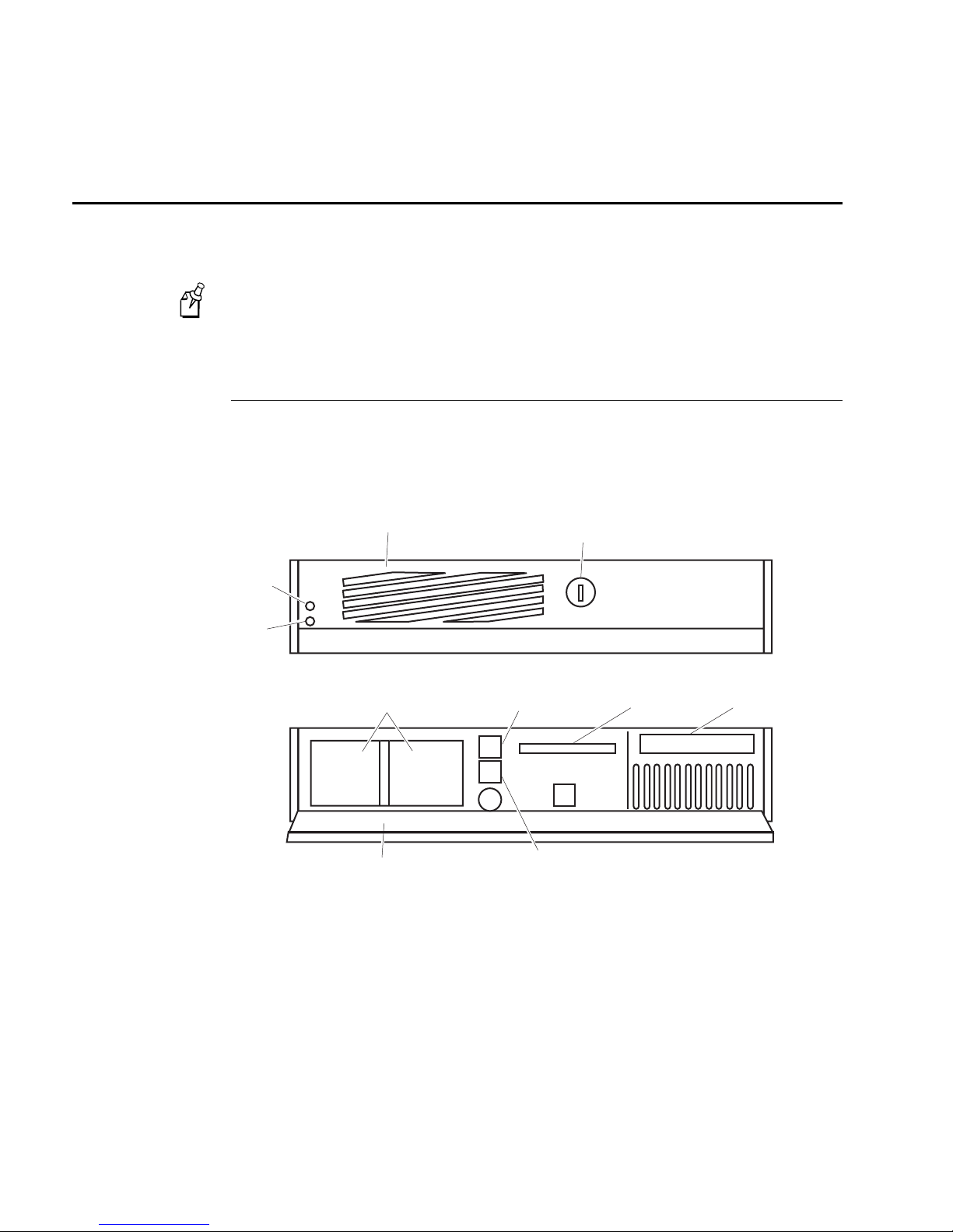
The DCS 300 contains several components on the front panel and on the rear panel that
you should be able to identify.
This user’s manual decscribes a DCS 300 with 0300D hardware. If you are
Note:
upgrading to software v1.6 and you have a DCS 300 with 0300A or 0300B hardware
your front and rear panels will look different. Refer to the user’s manual that shipped
with your DCS 300.
Understanding the Front Panel
The following illustration shows the front panel with the security panel up (lock
showing) and with the security panel down (On/Off button showing).
Component Description
Power LED Indicates that the DCS 300 has power.
Activate LED Indicates that the DCS 300 is on and is communicating.
Security panel and
lock
Fan Prevents your DCS 300 from overheating. When situating your DCS 300,
On/Off button Turns the power to the DCS 300 on and off.
1-6
Prevents unauthorized access to the Reset button, the On/Off button, the
disk drive, and the CD-ROM drive.
do not place it where the fan is obstructed.
Page 29
Getting Started
0300q001.eps
COM1
AC in
Fan
COM2
Mouse
port
Keyboard
port
Video
port
Ethernet
port
LPT1
1
Understanding the Front Panel (continued)
Component Description
Disk drive Enables you to install dcBrowser licenses, back up the configuration, etc.
CD-ROM drive Enables you to use the upgrade CD-ROM.
Reset button Reboots the DCS 300.
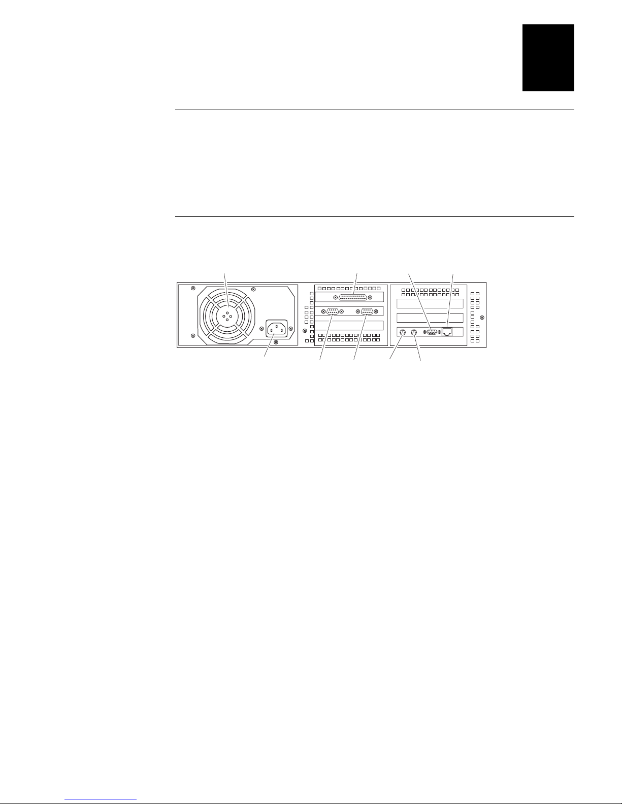
Understanding the Rear Panel
Component Description
Fan Prevents your DCS 300 from overheating. When situating your
DCS 300, do not place it where the fan is obstructed.
LPT1 Provides parallel port connection for accessories.
Video port Connects the monitor to your DCS 300.
Ethernet port Provides a 10/100 Mbps Ethernet connection.
AC in Connects to one end of the AC power cord that provides power to the
DCS 300.
COM1, COM2 Provides serial port connections for external Intermec controllers, a
modem, or other devices that require serial ports to connect to your
DCS 300.
Mouse port Connects a mouse to your DCS 300. Since the keyboard provides
mouse function keys, the DCS 300 does not come with a mouse.
Keyboard port Connects the keyboard to your DCS 300.
1-7
Page 30

DCS 300 User’s Manual
Plugging In the Power Cord
You need to attach the power cord before you can run the DCS 300. However, you will
want to plug the power cord into a surge protector or an uninterruptable power supply
(UPS). Intermec requires that you use a surge protector in locations that use 115 VAC.
Intermec requires that you use a UPS in locations that have wide variations in AC
power. For help, see “Connecting an Uninterruptable Power Supply” later in this
chapter.
Equipment
Power cord, 110V U.S. cord (standard)
•
Or,
Power cord, 220-250 VAC for UK (Part No. 586266)
Power cord, 220-250 VAC for Europe (Part No. 586267)
Surge protector
•
To connect the power cord
1. Locate the AC in port on the rear panel of the DCS 300.
2. Insert the power cord 3-pin connector into the AC in port.
3. Plug the other end of the power cord into an AC power outlet, surge protector, or
UPS.
1-8
Page 31

Connecting an Uninterruptable Power Supply
Intermec requires you to connect an uninterruptable power supply (UPS) to your
DCS 300. In case of a power failure, the UPS provides enough backup power to allow
the DCS 300 to properly shut down and minimize the loss of data.
If you experience a power failure after installing a UPS, these events will occur:
If power returns within 45 seconds, no error message is logged and no message
•
appears on the monitor.
If power does not return within 45 seconds, an error message is logged and this
•
message appears on the monitor.
Power failure. UPS is running on battery power. Stopping data
collection to preserve data integrity. DCS 300 shutdown will
occur in approx 5 minutes.
When data collection is stopped, the DCS 300 tries to shut down. Five minutes after
the error message is logged, the UPS cuts off power to the DCS 300.
Getting Started
1
You can configure the DCS 300 to automatically restart data collection when power
returns. For help, see “Setting the System Parameters” in Chapter 2.
Equipment
Uninterruptable power supply, North America (Part No. 589082)
•
Uninterruptable power supply, International (Part No. 589079)
9F-9M cable for auto-restoration (Part No. 589157)
•
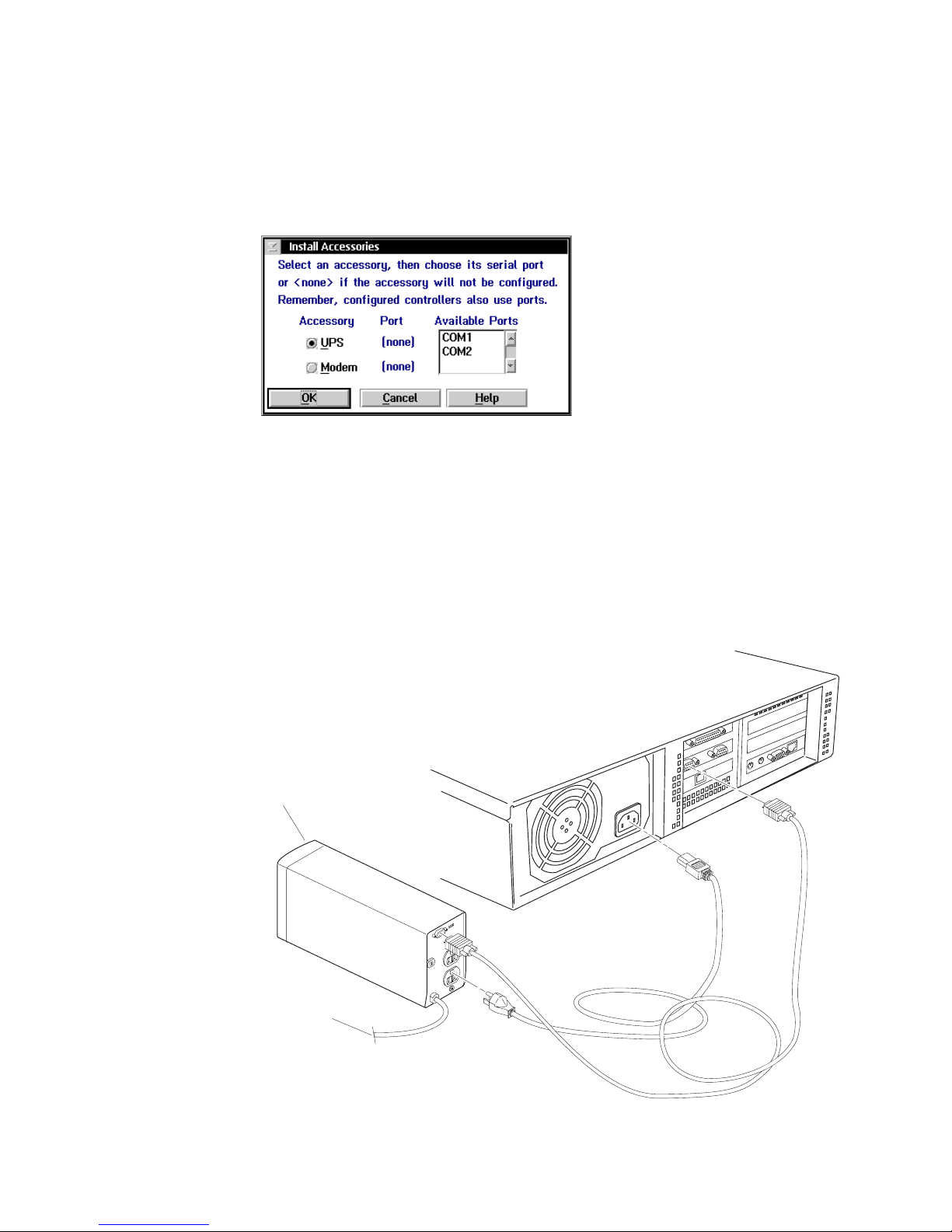
To connect a UPS
1. Make sure the DCS 300 is turned off. The power LED should be off.
2. Insert the DCS 300 power cord 3-pin connector into the AC in port.
3. Plug the other end of the power cord into the UPS.
4. (Optional) Plug the power cord of the UPS into the surge protector or an AC power
outlet.
5. Insert one end of the serial cable into the serial port on the UPS.
6. Insert the other end of the serial cable into a COM port on the DCS 300.
7. Press the power button on the DCS 300. The power LED turns on. The main screen
appears.
8. From the main screen sidebar buttons, choose System Maintenance. The System
Maintenance dialog box appears.
1-9
Page 32
DCS 300 User’s Manual
10. Choose UPS.
11. In the Available Ports list box, select the serial port on the DCS 300 that you used
12. Choose OK to save your changes.
13. Click Close.
9. In the System Maintenance list box, choose Install Accessories and then choose
Start. The Install Accessories dialog box appears.
to connect to the UPS.
14. Click Save and Activate and follow the instructions that appear. The DCS 300
reboots.
Uninterruptable
power supply
To AC power
1-10
300U007.eps
Page 33
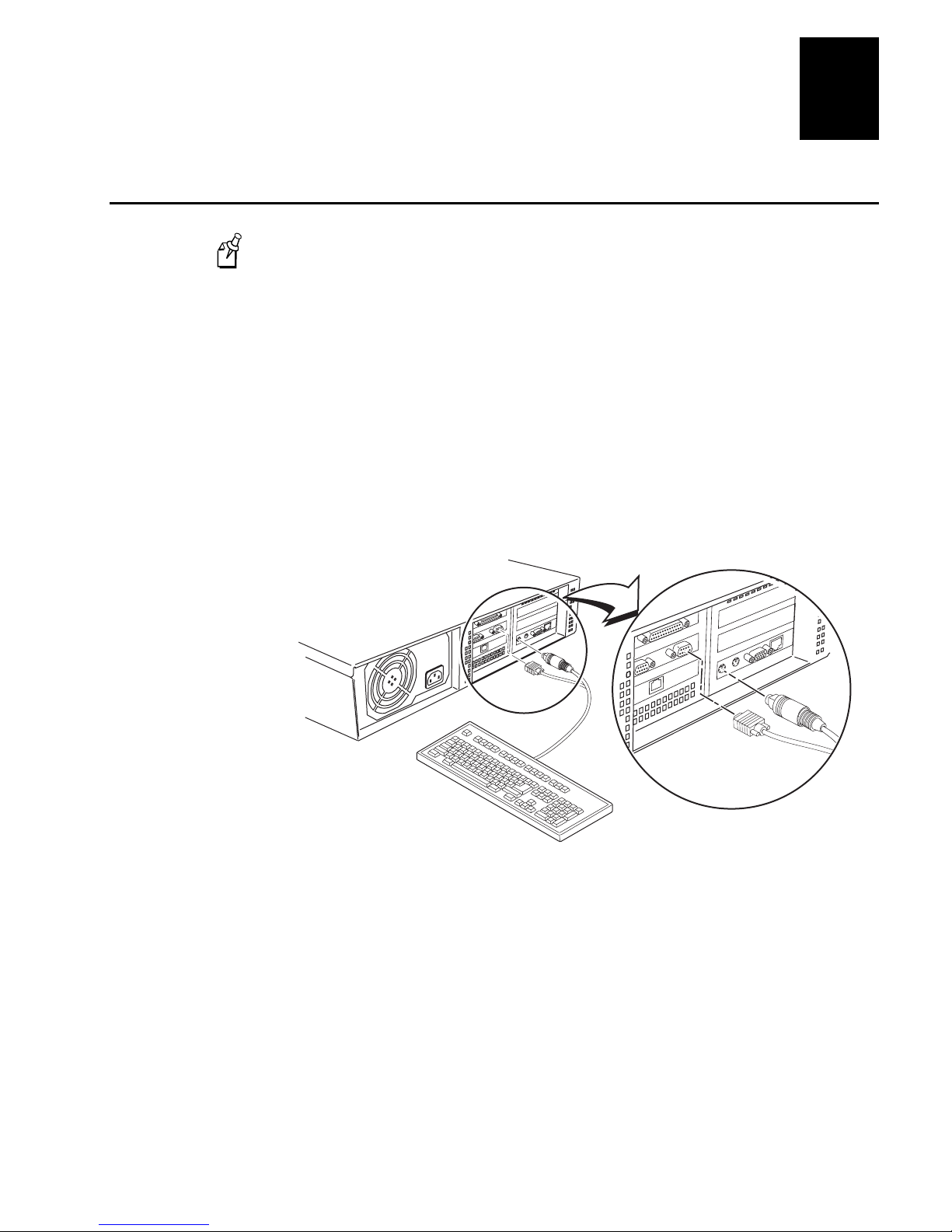
Plugging In the Keyboard
300U004.eps
If you have a DCS 300 with 0300A hardware, you must have the keyboard
Note:
connected to the DCS 300 whenever you boot it.
Equipment
Keyboard (standard)
•
To plug in the keyboard
1. Locate the keyboard port on the rear panel of the DCS 300.
2. Insert the keyboard adapter into the keyboard connector.
3. Insert the keyboard adapter into the keyboard port.
4. Insert the mouse connector into a COM port.
Getting Started
1
1-11
Page 34
DCS 300 User’s Manual
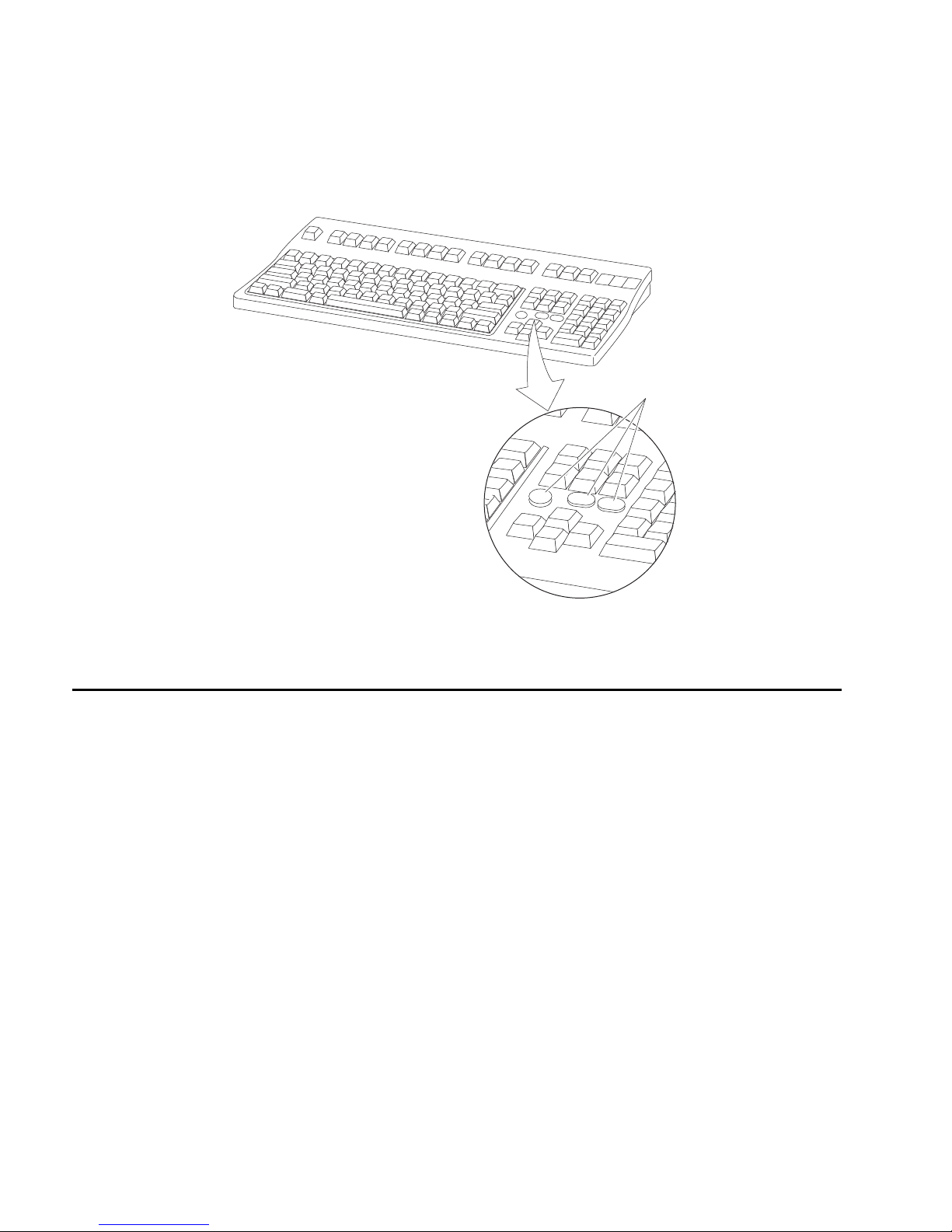
The keyboard has mouse function keys on it.
Mouse
function
keys
Connecting the Monitor
Equipment
Monitor with cable and power cord (not provided)
•
To connect the monitor
1. Locate the video port on the rear panel of the DCS 300.
2. Insert the monitor cable into the video port.
3. Insert one end of the power cord into the monitor and the other end into an AC
power outlet.
300U022.eps
1-12
Page 35
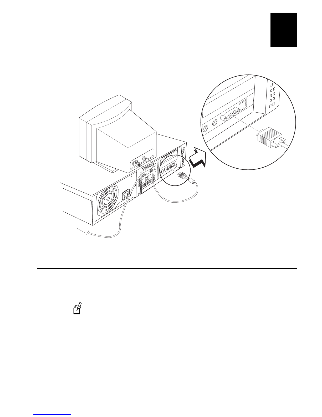
Connecting the Monitor (continued)
300U006.eps
To AC power
Getting Started
1
Connecting a Modem
You may want to connect your DCS 300 to a modem. If you are using the remote
console feature, you may want to use a modem to let you access the DCS 300 using a
PC with a modem.
You can also use the remote console support feature through a LAN or a WAN
Note:
connection.
Equipment
Modem (56 Kbps, external) with telephone cable and power cord for North
•
America (Part No. 590887)
International customers should use the U.S. Robotics Sportster modem
(56 Kbps, external).
1-13
Page 36
DCS 300 User’s Manual
9F-25M cable (RS-232, 183 cm/6 ft) to connect the modem to the DCS 300
•
(Part No. 589182)
To attach a modem
1. Make sure the DCS 300 is turned off. The power LED should be off.
2. Plug one end of the modem power cord into the modem and the other end into the
AC power outlet.
3. Plug one end of the telephone cable into the modem and the other end into an RJ-11
telephone jack.
4. Insert one end of the serial cable into the serial port on the modem.
5. Insert the other end of the serial cable into a COM port on the DCS 300.
6. Press the power button on the DCS 300. The power LED turns on. The main screen
appears.
7. From the main screen sidebar buttons, choose System Maintenance. The System
Maintenance dialog box appears.
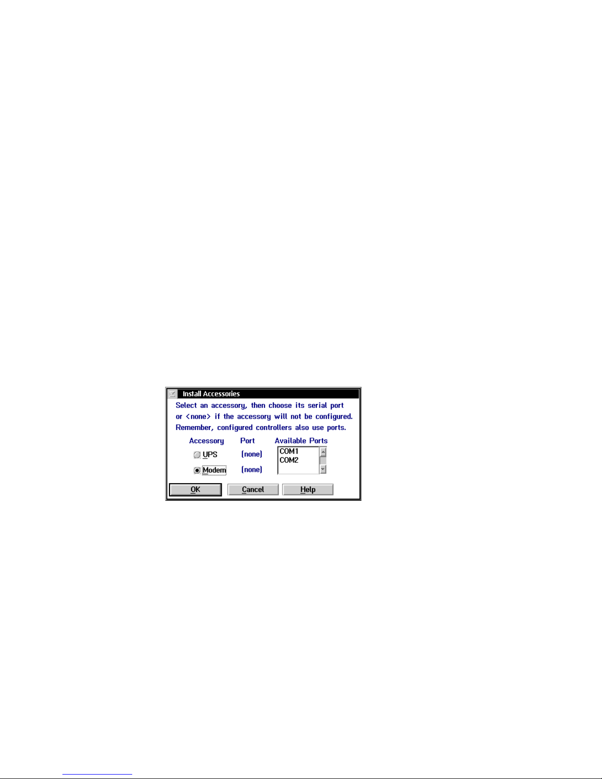
8. In the System Maintenance list box, select Install Accessories and then choose
Start. The Install Accessories dialog box appears.
9. Choose Modem.
10. In the Available Ports list box, select the serial port on the DCS 300 that you used
to connect to the modem.
11. Choose OK to save your changes.
1-14
Page 37
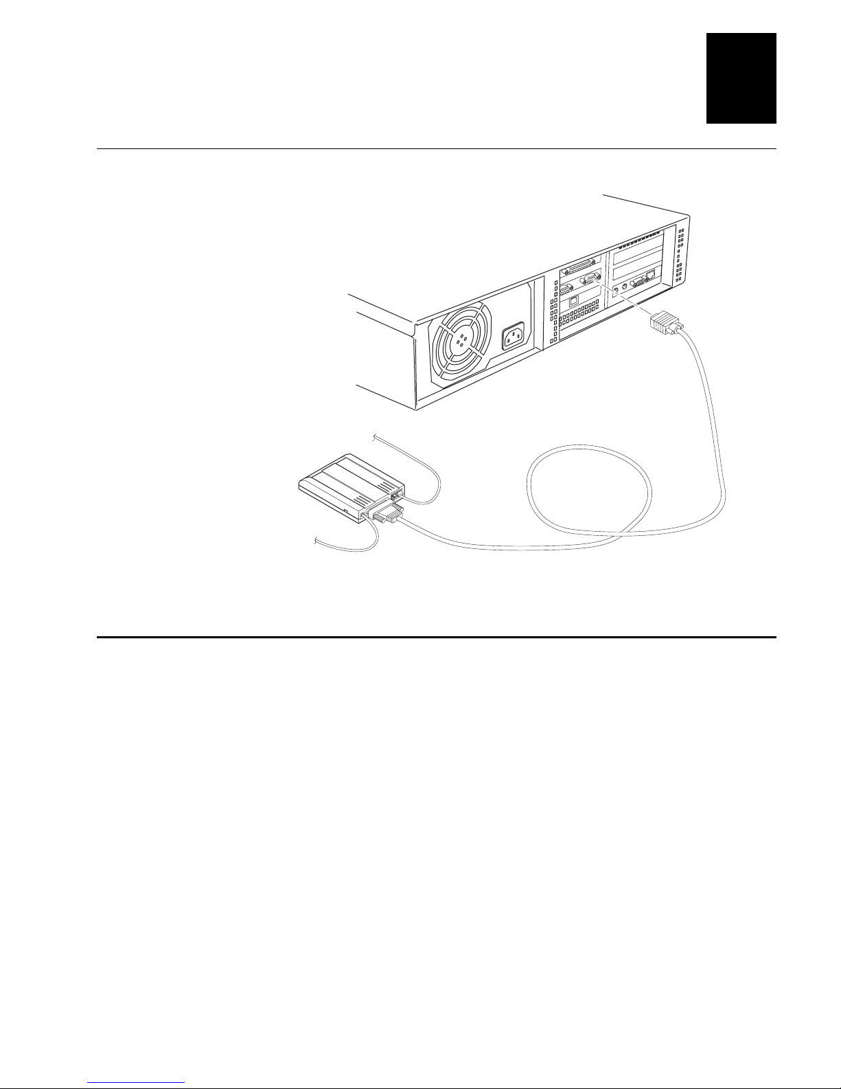
Connecting a Modem (continued)
300U008.eps
To
phone line
To AC power
Getting Started
1
Mounting the DCS 300 in a Rack
This section explains how to mount your DCS 300 in a rack. When installing the server
in a closed or multi-unit rack assembly, you must follow these requirements:
Do not exceed the maximum recommended ambient temperature (Tmra), which is
•
50°C. Make sure that you consider that the ambient temperature of the rack
environment may exceed the room temperature.
Do not block the vents found at the front or the rear of the server. If you reduce the
•
amount of free air to these ventilation openings, you may affect the server
operation.
Do not mount the server in any way that may make the rack unstable because of
•
uneven mechanical loading.
Make sure that you consider the combined electrical loads on the supply circuit of
•
all the equipment that is installed in the rack, including the overcurrent protection
and the supply wiring. Use the nameplate ratings of the equipment.
Make sure that you maintain the integrity of the earth ground. If the server is not
•
connected directly to the branch circuit, then the power strip (or equivalent) must
have a reliable earth ground connection.
1-15
Page 38
DCS 300 User’s Manual
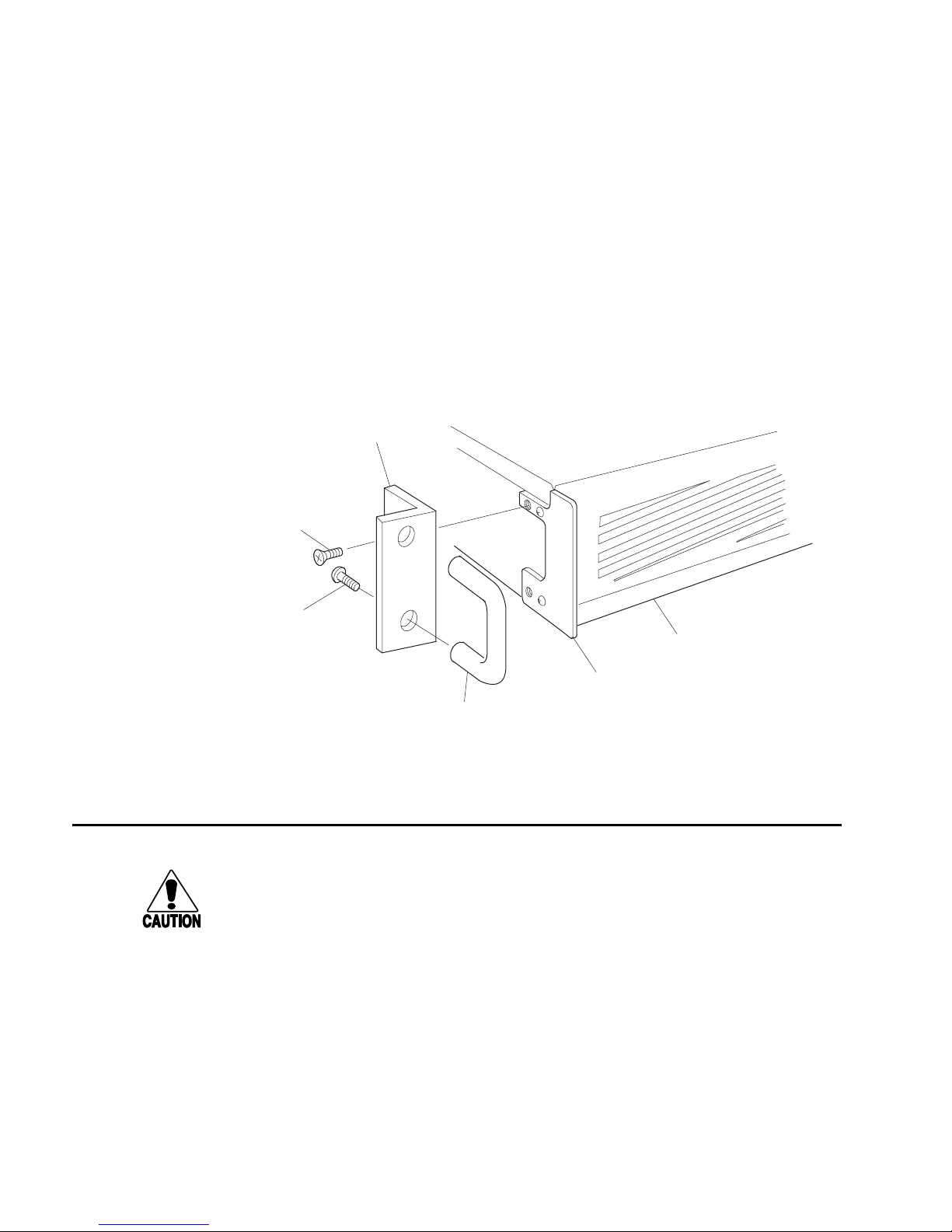
To mount the DCS 300 in a rack
1. Locate the two rack handles, two rack ears, four flat head screws, and four round
head screws that shipped with the DCS 300.
2. Secure the rack handles to the front of the rack ears with the flat head screws.
3. Secure the rack ears to the right and left sides of the DCS 300 over the security
panel plates with the round head screws.
Rack
ear
Round head
screw
(2 places)
Flat head
screw
(2 places)
Rack
handle
Turning the DCS 300 On and Off
Caution
Always choose Shutdown DCS 300 before rebooting or turning off the server. If you
do not shut down the server properly, you may lose data or damage files on the
server.
Conseil
Vous devez toujours arrêter le DCS 300 avant de le réinitialiser ou de l’éteindre. Si
vous n’arrêtez pas correctement le DCS 300, il est possible que des données soient
perdues ou que des fichiers soient endommagés sur le serveur.
300U025.eps
Security
panel
Security
panel plate
1-16
Page 39
Getting Started
Turning On the DCS 300
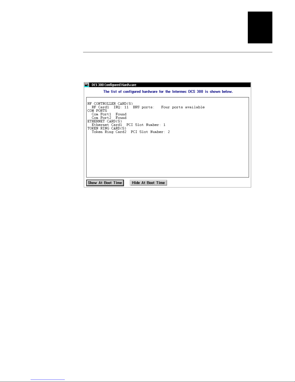
Push the On/Off button. The DCS 300 Configured Hardware dialog box appears.
•
1
This dialog box lists the network adapter cards in your DCS 300. Choose one of the
following:
If you want this dialog box to appear every time the DCS 300 boots, choose Show
•
at Boot Time. This dialog box may be helpful when troubleshooting the DCS 300.
If you never want this dialog box to appear, choose Hide at Boot Time.
•
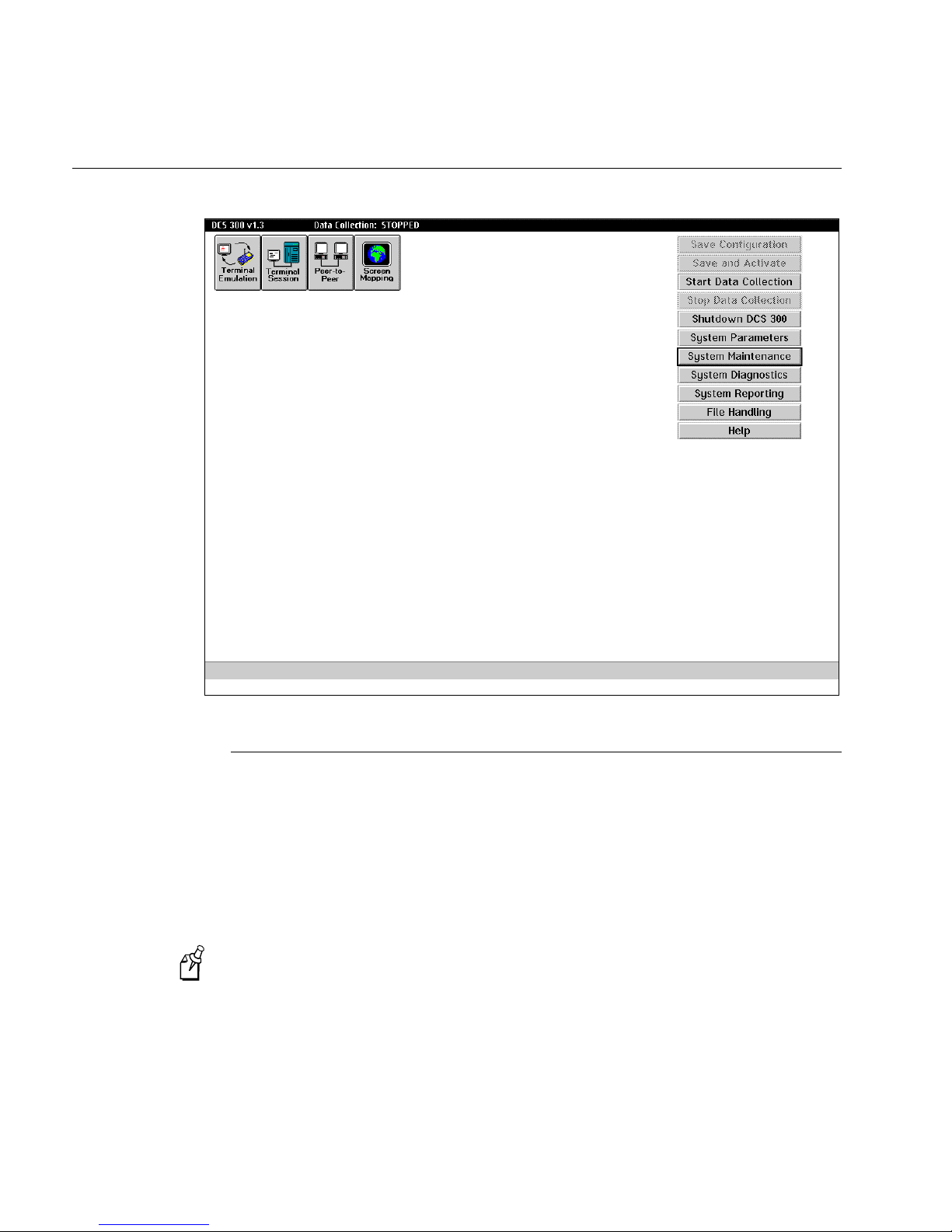
The DCS 300 window appears.
1-17
Page 40
DCS 300 User’s Manual
DCS 300 Window
Turning Off the DCS 300
You may need to turn off the DCS 300 for maintenance or relocation. Before you push
the On/Off button on the front panel, you must shut down the DCS 300.
When you shut down the DCS 300, it performs a series of activities to ensure that no
system files or data are lost. This process may take several minutes.
If you are using the DCS 300 local interface and you want to reboot the DCS 300 to
activate your changes, from the Shutdown DCS 300 message box choose Restart.
If you are using Remote Console, you must choose the Restart button. You
Note:
cannot choose Shutdown and then press
If you are using the Web browser interface and you want to reboot the DCS 300, from
the DCS 300 Management page choose Reboot.
1-18
Ctrl-Alt-Del
.
Page 41
Getting Started
To turn off the DCS 300
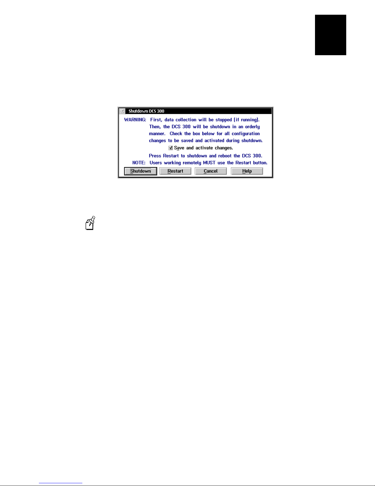
1. From the main screen sidebar buttons, choose Shutdown DCS 300. The Shutdown
DCS 300 message box appears.
2. Check or clear the Save and activate changes check box. If you want to save and
activate the changes you made to the configuration, check this check box.
If you saved your changes without activating them (only [Activate] appears
Note:
in the title bar), this check box is grayed. The DCS 300 will automatically activate
your changes before it shuts down.
1
3. Choose Shutdown to shut down the DCS 300. The DCS 300 needs to perform a
series of shutdown activities, which may take several minutes. A message box
appears letting you know when you can safely turn off the DCS 300.
Or, choose Restart if you want to shut down and restart the DCS 300. You may
want to restart the DCS 300 to activate your changes.
4. Push the On/Off button. The DCS 300 turns off.
1-19
Page 42

blank
Page 43

2
Learning About the DCS 300
Page 44

DCS 300 User’s Manual
blank
Page 45

This chapter explains the DCS 300 local and Web browser interfaces and how to
navigate through them, how to use the online help, how to configure the system date
and time and the system parameters, and how to maintain your configuration.
Chapter Checklist
Done? Task Page
Learning About the DCS 300
2
Learn about the DCS 300 local interface and how to navigate
Y
through it.
Learn about the Web browser interface and how to navigate
Y
through it.
Set the date and time. 2-12
Y
Set the system parameters. 2-14
Y
Understand the configuration files and how to restore the default
Y
configuration.
Understand how to back up and restore the system and user files
Y
on your DCS 300.
Understand how to start and stop the downline data collection
Y
network.
Know how to access a command prompt. 2-25
Y
If you already understand and have performed these tasks, connect the DCS 300 to your
host as described in this chapter:
2-4
2-9
2-16
2-17
2-23
Chapter 3, “Connecting to the Upline Network”
•
2-3
Page 46

DCS 300 User’s Manual
About the DCS 300 Local Interface
You access the DCS 300 local interface when you turn on the DCS 300 while you have
a monitor connected to it or you are using the remote console feature. You use this
interface to
configure the upline network.
•
configure the data collection environment.
•
configure the host communications environment.
•
configure the host environment parameters.
•
manage the data collection network.
•
set system parameters.
•
perform system maintenance.
•
run diagnostics.
•
perform system reporting.
•
manage system, runtime, and user files.
•
upgrade your DCS 300 software and licenses.
•
upgrade your Trakker Antares terminals.
•
2-4
Page 47
Learning About the DCS 300
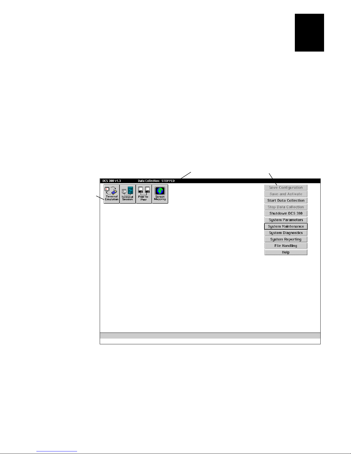
The DCS 300 local interface has three parts:
Title bar The title bar at the top of the screen contains the name and version. It also
lets you know if data collection is started or stopped. If you are configuring the
DCS 300, [Save] and [Activate] may appear in the title bar. These prompts remind you
that you have made changes to the configuration that have not been saved or activated.
When you choose Save Configuration or Save and Activate, these prompts disappear.
Toolbar buttons The buttons on the screen define the host environment to which you
are connecting the DCS 300.
Sidebar buttons The buttons on the right side of the screen perform system functions
on the DCS 300 such as backing up the configuration files, viewing Hot Standby files,
and defining system parameters.
2
Toolbar buttons
Title bar
Sidebar buttons
2-5
Page 48

DCS 300 User’s Manual
Getting Help
The DCS 300 local interface includes online help that provides descriptions of the
DCS 300 toolbars, dialog boxes, and options. Help also provides procedural
information and limited background information.
To get help
In any open dialog box, choose the Help button.
•
The Help window opens and displays the topic for the toolbar or dialog box you were
using. If you requested help from the main screen, the Getting Started topic appears.
You can resize and move your Help window to see more of a topic at one time or to see
more of the configuration window.
Once the Help window appears, you operate the Help system by selecting topics, by
choosing commands from the Help menus, or by choosing the Help control buttons at
the bottom of the Help window. Topics that you can jump to are shown in colored or
underlined text.
To jump to another help topic
Double-click the topic name. Or, press
•
press
To use the help control buttons
Choose Previous. Or, press
•
Choose Search to search for help on a specific word or phrase.
•
Choose Index to look up a topic in the index.
•
Choose Contents to look up a topic in the contents.
•
Enter
.
.
Esc
until the topic is highlighted, and then
Tab
2-6
Page 49

Learning About the DCS 300
2
Navigating Through Dialog Boxes
In the DCS 300 local interface, there are various ways that you can move through
dialog boxes:
To Do This Action Do This Action
Move between fields in a dialog box Use the mouse to click a field and the cursor
moves there.
Use
field.
Press
underlined in the field or button name.
Activate the buttons in a dialog box Use the mouse to click them.
Press
the button name.
If any button is highlighted, choose another
button by pressing the letter underlined in the
button name without pressing
Go to the end of a file
Go to the top of a file
Access a window that shows you which
applications are running
Press
Press
Press
to move the cursor from field to
Tab
or
Ctrl
Ctrl
Ctrl-End
Ctrl-Home
Ctrl-Esc
and then the letter
Alt
or
and the letter underlined in
Alt
.
.
.
Ctrl
or
Alt
.
2-7
Page 50

DCS 300 User’s Manual
Understanding the Dialog Box Buttons
These are the most common buttons that appear in the dialog boxes when you are
configuring the DCS 300.
Button Description
OK
Cancel
Help
Close
Add
Edit
Delete
Choose OK to save any changes you have made in the dialog box and exit from
that dialog box. Your changes are saved in RAM. To save your changes to disk,
from the main screen sidebar buttons choose Save Configuration.
Choose Cancel to not save any changes you have made in the dialog box and
exit from that dialog box.
Choose Help in any dialog box to obtain help on the fields in that dialog box.
Choose Close to exit a dialog box.
Choose Add to add a new item such as a host. A dialog box appears. Enter the
values into the fields. Choose OK to add the item. Choose Cancel to remove the
item.
Select the item you want to change and choose Edit. A dialog box appears. Edit
the values in the fields. Choose OK to save the change. Choose Cancel to
restore the original values of the item.
Select the item you want to remove and choose Delete. A message box appears
confirming that you want to delete the item. Choose Delete.
Note: You may not be able to delete an object if it is linked to another object.
2-8
Page 51

About the Web Browser Interface
The Web browser interface lets you view, configure, and manage features of the
DCS 300 using a Web browser on your PC. You can use a Web browser to
access the DCS 300 home page and get information about its status.
•
start or stop the dcBrowser gateway.
•
manage the DCS 300.
•
run dcBrowser diagnostics.
•
access the Intermec Product Support Web page.
•
Opening the DCS 300 Home Page
The home page appears when you enter the DCS 300 IP address in the Address line or
the Go to line in your Web browser. It gives you information about the DCS 300, such
as its name and its software version.
Learning About the DCS 300
2
If you have a DNS server, you can enter the logical name for the DCS 300
Note:
instead of the IP address to access the home page.
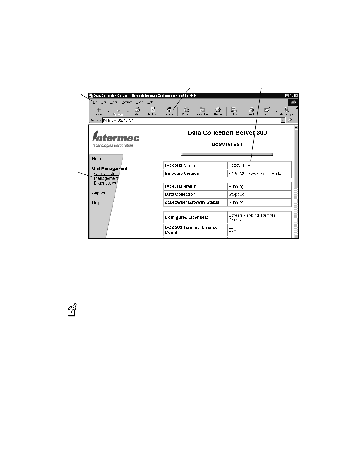
The DCS 300 home page has these parts:
Web browser menu This menu at the top of the window helps you configure, operate,
and navigate the Web browser. For help, select Help from the Web browser menu.
Web browser buttons These buttons at the top of the window help you navigate
through the Web browser. For help, select Help from the Web browser menu.
Navigation menu This menu on the left side of the window lets you access the
DCS 300 pages.
Web page The Web page displays the information that you requested through the
navigation menu.
When you open the DCS 300 home page, your home page may look different,
Note:
depending on your Web browser.
2-9
Page 52
DCS 300 User’s Manual
enu
DCS 300 Home Page
Web browser
menu
Navigation
m
Web browser
buttons
Web page
You can open the DCS 300 home page from a PC that has a Web browser and is
connected to your Intranet. Before you can remotely connect to the DCS 300, you must
configure it for the Ethernet or token ring network. For help, see Chapter 3,
“Connecting to the Upline Network.”
To open the DCS 300 home page
If you access the Internet by using a proxy server, you must add the IP address of
Note:
the DCS 300 to your Exceptions list. The Exceptions list contains the addresses that
you do not want to use with a proxy server.
1. Start a Web browser on your PC.
2. In the Address line or the Go to line, enter http:// and the IP address of the DCS 300
and then press
http://129.10.15.167
. For example,
Enter
The DCS 300 home page appears.
2-10
Page 53
Learning About the DCS 300
2
Getting Help
If you need help configuring, maintaining, or troubleshooting the DCS 300 in the Web
browser interface, you can use the online help.
To get an overview of how to use the DCS 300
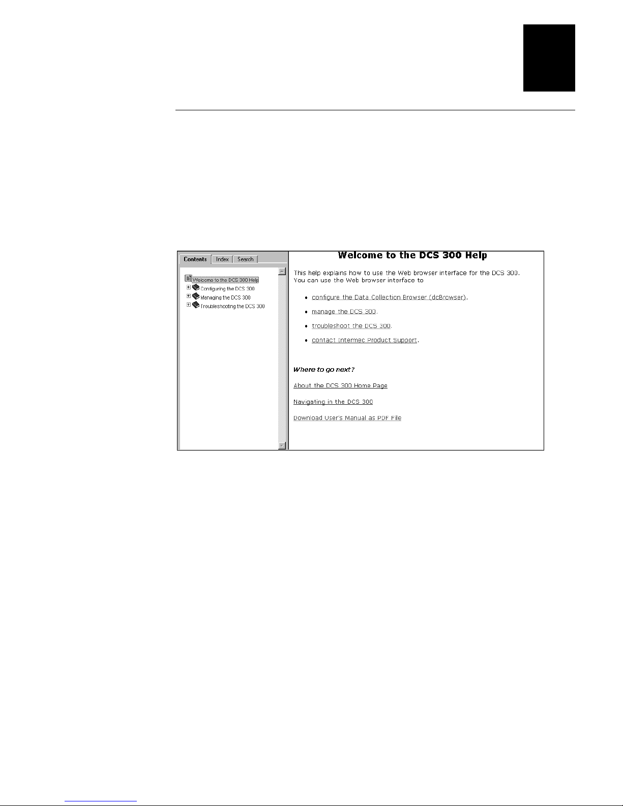
From the navigation menu, click Help. The Welcome to the DCS 300 Help page
•
appears.
To the left of the Welcome page are the Contents, Index, and Search tabs. Use the
Contents tab to display the “books” that are available. Double-click the books to display
pages that contain procedures.
To get help on configuring the DCS 300
1. From the navigation menu, click Configuration.
2. If a security screen appears, type
Password field, and click OK. You must type Intermec in uppercase letters.
3. In the lower left corner of the page, click Help.
INTERMEC
in the User Name field and in the
2-11
Page 54
DCS 300 User’s Manual
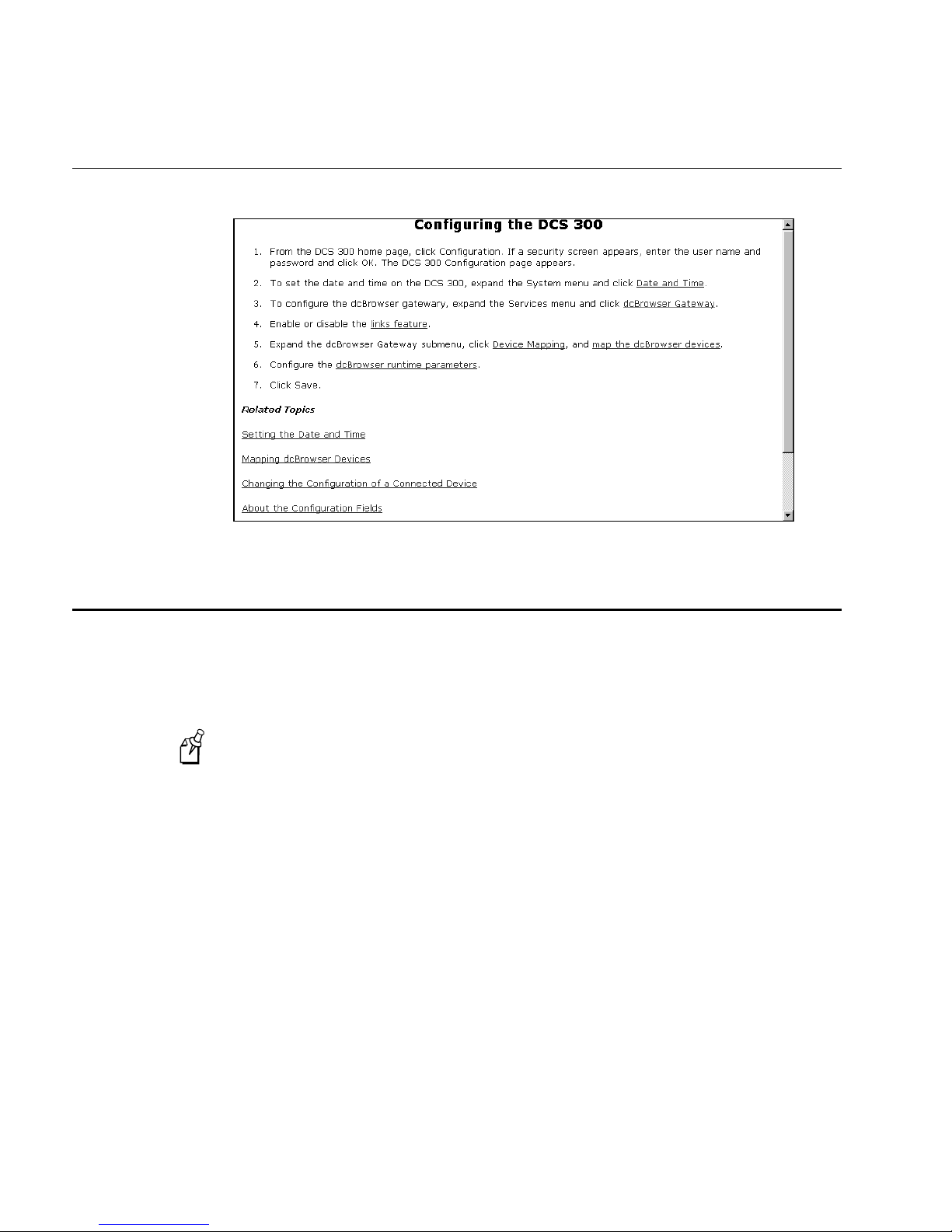
Configuring Help
Setting the Date and Time
You may need to set the current date and time on the DCS 300. When you open the
Change Date and Time page, you will see the DCS clock, which is the date and time
that is set on the DCS 300 and the local browser clock, which is the date and time that
is set on your PC.
When you choose the Change Now button, you immediately change the date and
Note:
time on the DCS 300.
To set the date and time
1. Open the DCS 300 home page. For help, see “About the Web Browser Interface”
earlier in this chapter.
2. Click Configuration. If a security screen appears, type
field and in the Password field, and click OK. You must type Intermec in uppercase
letters. The DCS 300 Configuration page appears.
INTERMEC
in the User Name
2-12
Page 55
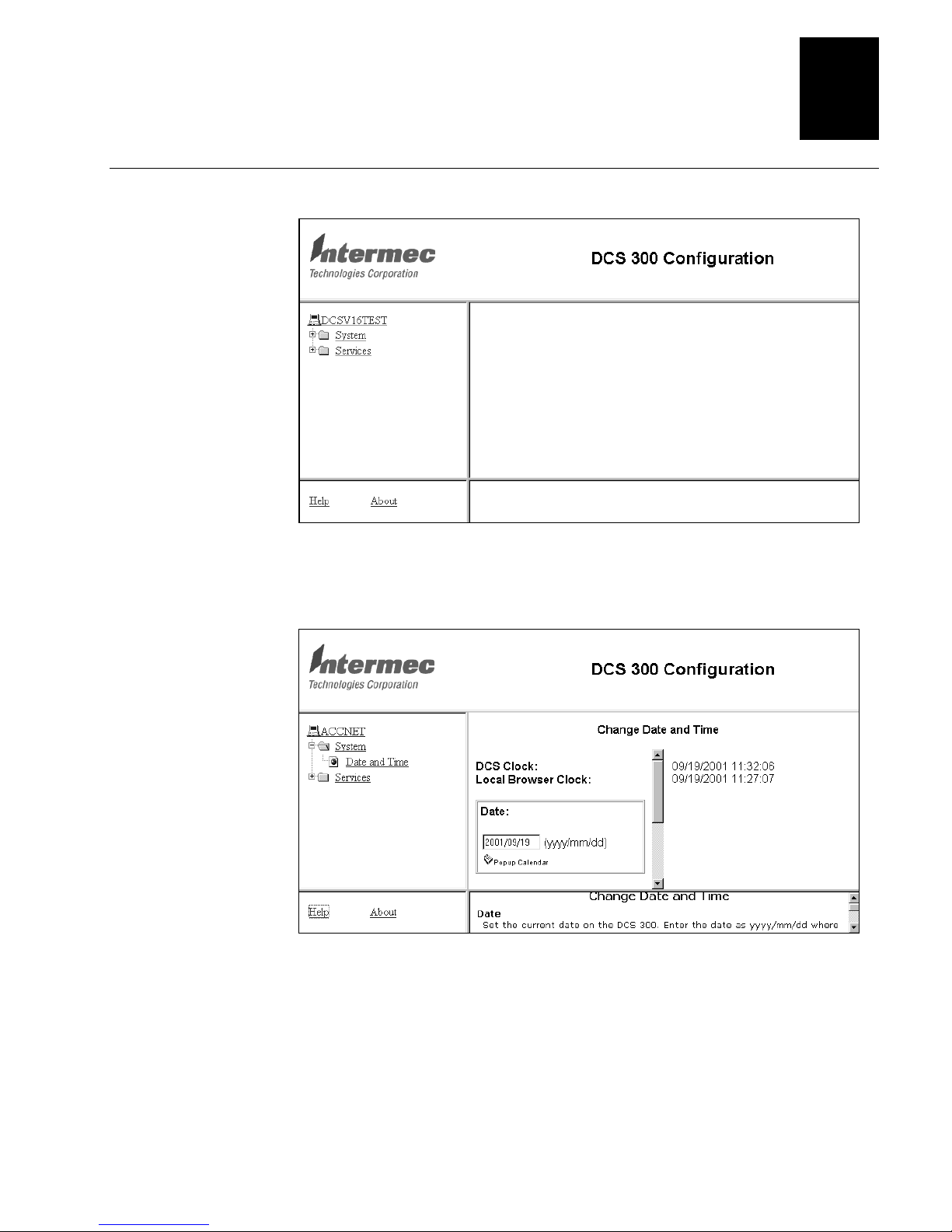
DCS 300 Configuration Page
Learning About the DCS 300
2
3. Expand the System menu, and click Date and Time. The Change Date and Time
page appears.
4. Enter the date in the date field, or click the Popup Calendar to select a date.
5. Enter the time in the time field.
6. Click Change Now. The date and time are now set to what you selected.
2-13
Page 56
DCS 300 User’s Manual
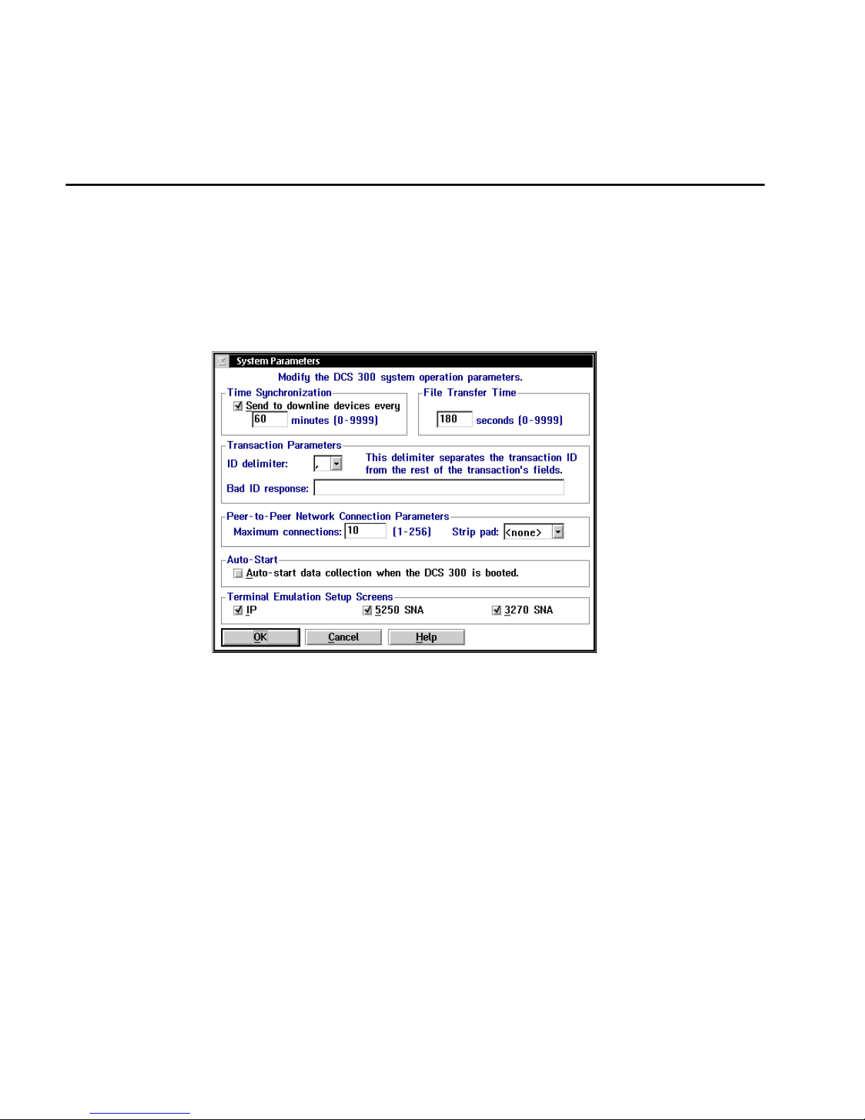
Setting the System Parameters
When you set system parameters, you are defining the operating parameters for the
DCS 300.
To set the system parameters
From the main screen sidebar buttons, choose System Parameters. The System
•
Parameters dialog box appears.
2-14
Page 57

Learning About the DCS 300
Field Description Value Default
2
Send to downline
devices every...
...minutes This field specifies how often in minutes the
File Transfer Time This box specifies how long in seconds the
ID delimiter The character that the devices use to separate
Bad ID response
(Optional)
Maximum
connections
(Peer-to-peer)
This check box determines if the DCS 300
sends its time to all Intermec controllers.
Note: The time broadcast is not necessarily
sent to the devices that are connected to the
Intermec controllers. However, when you
configure a controller, you can configure it to
broadcast the time to its devices.
DCS 300 sends the time synchronization
message.
DCS 300 waits for a response from the device
when it is downloading files before it times
out.
the transaction ID from the transaction fields.
The message that the DCS 300 sends to the
source of the transaction if the DCS 300 does
not recognize the transaction ID. Use this field
if you want to make sure that there is always a
response for a failed delivery of a transaction.
A tuning value that defines the maximum
number of connections for each NetComm
process.
Check, Clear Check
0 to 9999 60
0 to 9999 180
Predefined , (comma)
1 to 40
alphanumeric and
special characters
1 to 256 10
None
Strip pad
(Peer-to-peer, APPC
only)
Auto-Start This check box determines if the DCS 300
Terminal Emulation
Setup Screens
(Optional)
The pad character, which is used by fixedlength transactions from a host application,
that you want the DCS 300 to remove before
sending the transaction.
starts data collection when it is booted.
This box lets you customize which terminal
emulation buttons appear in the main screen.
Predefined None
Check, Clear Clear
IP, 5250 SNA, 3270
SNA
All checked
2-15
Page 58
DCS 300 User’s Manual
About the Configuration Files
The DCS 300 uses three configuration files:
Default This configuration is the factory default configuration. If you want to restore
the default configuration, for example if you want to move the DCS 300 to a new
system, select this option. For help, see “Restoring the Default Configuration” in the
next section.
Current When you choose Save Configuration, the DCS 300 updates the current
configuration file. The DCS 300 does not change the active configuration file. Having
separate files for the current and active configurations lets you make changes while the
DCS 300 is running without interrupting data collection.
Active When you choose Save and Activate, the DCS 300 stops data collection and
copies the current configuration file to the active configuration file. When you restart
data collection, the active configuration file is the file that the DCS 300 uses.
Restoring the Default Configuration
You can use the DCS 300 local interface to restore the current default configuration.
This procedure stops data collection, discards any unsaved and unactivated changes,
and reboots the DCS 300. If you have used the Install Accessories dialog box to
connect a modem or UPS or if you have upgraded your screen mapping license, then
your new settings become the current default configuration.
If you want to load your backed up system files or runtime configuration, see
“Restoring Your System Files and Runtime Configuration” or “Restoring Your User
Files” later in this chapter.
To restore the default configuration
1. From the main screen sidebar buttons, choose System Maintenance. The System
Maintenance dialog box appears.
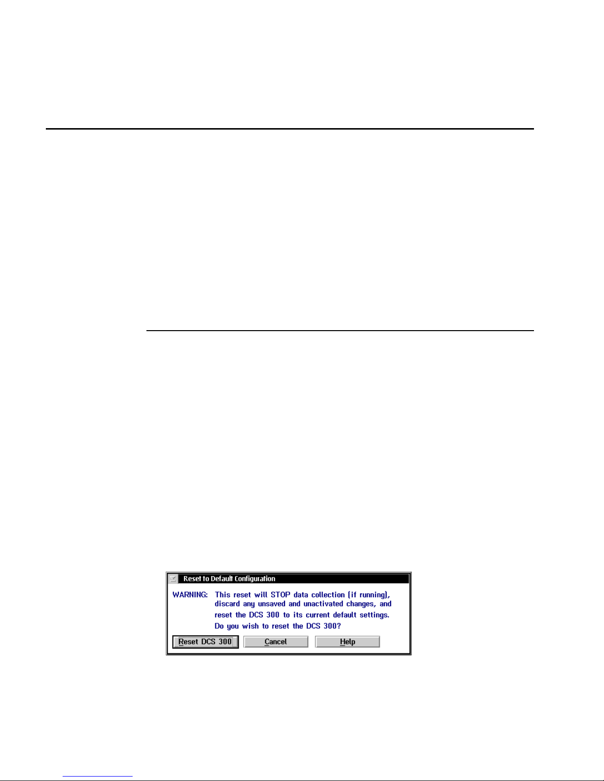
2. In the System Maintenance list box, select Reset to Default Configuration and then
choose Start. The Reset to Default Configuration message box appears.
3. Choose Reset DCS 300. You return to the main screen.
2-16
Page 59
Learning About the DCS 300
4. Choose Save and Activate to make the default configuration the active
configuration.
5. Choose Shutdown DCS 300 to shut down the DCS 300.
2
6. Press
Ctrl-Alt-Del
to reboot the DCS 300.
Backing Up the DCS 300 Configuration
Once you have configured your Intermec hardware, have set up your host
communications, and have set up your host environment parameters, you can start data
collection on your DCS 300.
Intermec recommends that you back up your system files and your runtime
configuration before you start data collection.
Backing Up Your System Files and Runtime Configuration
You use the DCS 300 local interface to back up your system files and runtime
configuration to a floppy disk. When you opened the DCS 300 package, you unpacked
a blank, formatted, 3.5-inch disk. Use this disk to back up your system files and runtime
configuration. If your DCS 300 loses its configuration, you can use these files to restore
the DCS 300.
You can also use the Web browser interface to back up your system files and runtime
configuration. These backed up files are stored with the current date on the DCS 300
hard drive. The DCS 300 also periodically performs automatic backups of the
configuration.
To back up the configuration using the DCS 300 local interface
1. From the main screen sidebar buttons, choose System Maintenance. The System
Maintenance dialog box appears.
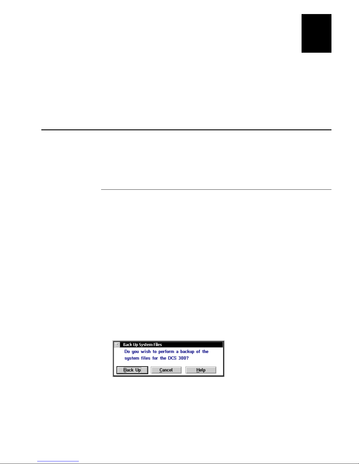
2. In the System Maintenance list box, select Backup System Files and then choose
Start. The Back Up System Files message box appears.
3. Choose Back Up. A message box appears prompting you to insert the floppy disk in
the disk drive.
2-17
Page 60

DCS 300 User’s Manual
4. Insert the 3.5-inch disk into the DCS 300 disk drive. The DCS 300 backs up the
system files and runtime configuration.
5. Remove your disk from the disk drive, label it, and put it in a safe place.
To back up the configuration using the Web browser interface
1. From the DCS 300 home page, click Management.
2. If a security screen appears, type
INTERMEC
in the User Name field and in the
Password field, and click OK. You must type Intermec in uppercase letters.
3. Click Back Up. A message box appears confirming that you want to back up the
current configuration of the DCS 300.
4. Choose OK. A message box appears informing you when the backup is completed.
5. Choose OK.
Backing Up Your User Files
You must back up any user files so that you can restore them if your DCS 300 loses its
configuration. For example, if you are using screen mapping, you may want to back up
your script (.SCR) files. You may also want to back up the
contains error messages.
When backing up your user files, you must use a separate 3.5-inch disk from the
Note:
one you used to back up your runtime configuration.
To back up your user files
1. From the main screen sidebar buttons, choose File Handling. The File Handling
dialog box appears.
NGERROR.LOG
file, which
2. In the File Handling list box, select Back Up User Files and then choose Start. The
Back Up User Files dialog box appears.
3. In the root directory list box (\), add all the files that you want to back up to the
Selected Files list box.
a. Select the file name. Script files are in the subdirectory
files are in the subdirectory TPL.
b. Choose Select. The file name appears in the Selected Files list box.
4. In the Selected Files list box, remove any files that you do not want to back up.
a. Select the file name.
b. Choose Remove. The file name is removed from the Selected Files list box.
5. Choose Back Up. A message box appears prompting you to insert a floppy disk in
the disk drive.
2-18
SCRIPTS
. Template
Page 61
6. Insert a 3.5-inch disk into the DCS 300 disk drive. The DCS 300 backs up the user
files you selected.
7. Remove your disk from the disk drive, label it, and put it in a safe place.
Restoring the DCS 300 Configuration
If your DCS 300 loses its configuration, you can recover the system files and runtime
configuration.
Restoring Your System Files and Runtime Configuration
You can restore your system files and runtime configuration using the DCS 300 local
interface or using the Web browser interface. When you used the DCS 300 local
interface to back up the system files and runtime configuration, you stored these files
on a floppy disk. You can use the DCS 300 local interface to restore these files from the
disk.
When you used the Web browser interface to back up the system files and runtime
configuration, you stored these files on the DCS 300 hard drive. The DCS 300 also
periodically performs automatic backups of the configuration. You can use the Web
browser interface to restore either a manual backup or an automatic backup.
Learning About the DCS 300
2
To restore the configuration using the DCS 300 local interface
1. From the main screen sidebar buttons, choose System Maintenance. The System
Maintenance dialog box appears.
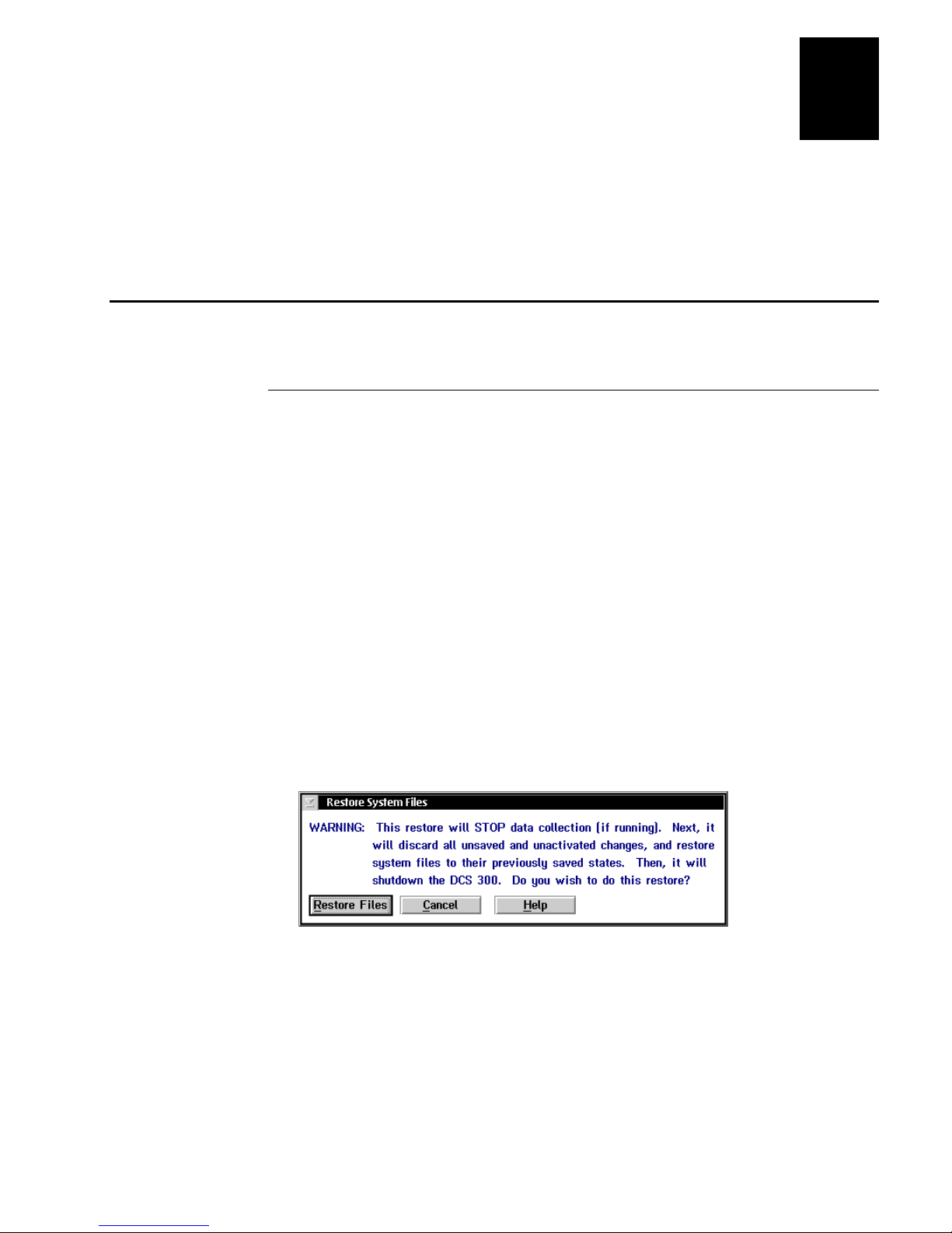
2. In the System Maintenance list box, select Restore System Files and then choose
Start. The Restore System Files message box appears.
3. Choose Restore Files. A message box appears prompting you to insert the floppy
disk that contains the backed up system files.
4. Insert the 3.5-inch disk that contains the system files and runtime configuration
backup into the DCS 300 disk drive. The DCS 300 restores the system files and
runtime configuration and then shuts down.
5. Remove your disk from the disk drive and put it in a safe place.
2-19
Page 62
DCS 300 User’s Manual
6. Press
To restore the configuration using the Web browser interface
1. From the DCS 300 home page, click Management.
2. If a security screen appears, type
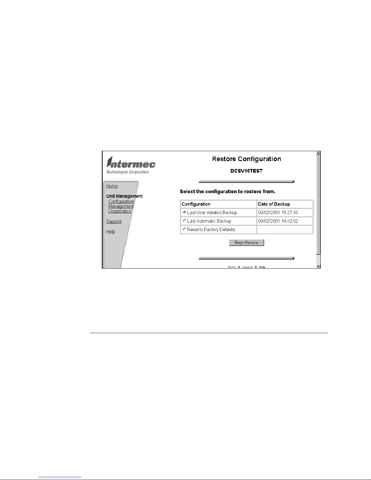
3. Choose Restore. The Restore Configuration page appears.
Ctrl-Alt-Del
Password field, and click OK. You must type Intermec in uppercase letters.
to reboot the DCS 300.
INTERMEC
in the User Name field and in the
2-20
4. Choose Last User Initiated Backup or choose Last Automatic Backup.
5. Choose Begin Restore. A message box appears informing you when the restore is
completed.
6. Choose OK.
Restoring Your User Files
You can also use this feature to transfer files, such as validation files or applications,
from a floppy disk to the DCS 300.
To restore your user files
1. Insert the 3.5-inch disk that contains the backup of your user files into the DCS 300
disk drive.
2. From the main screen sidebar buttons, choose File Handling. The File Handling
dialog box appears.
Page 63
Learning About the DCS 300
3. In the File Handling list box, select Restore User Files and then choose Start. A
message box appears with instructions to insert the disk in the drive of the
DCS 300.
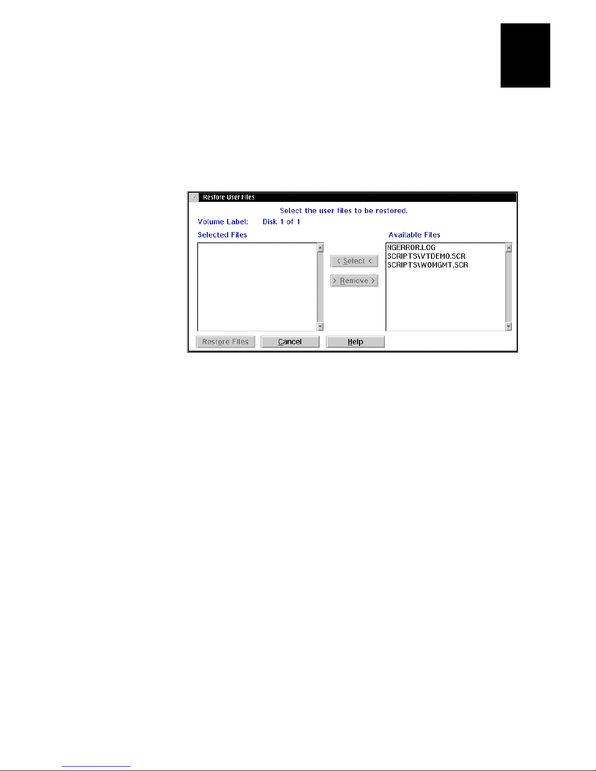
4. Choose OK. The Restore User Files dialog box appears. The files on the floppy
disk appear in the Available Files list box.
2
5. In the Available Files list box, add all the files that you want to restore to the
Selected Files list box.
a. Select the file name.
b. Choose Select. The file name appears in the Selected Files list box.
6. In the Selected Files list box, remove any of the files that you do not want to
restore.
a. Select the file name.
b. Choose Remove. The file name is removed from the Selected Files list box.
7. Choose Restore Files. The DCS 300 restores the files you selected.
8. Remove your disk from the disk drive and put it in a safe place.
2-21
Page 64
DCS 300 User’s Manual
Deleting User Files
1. From the main screen sidebar buttons, choose File Handling. The File Handling
dialog box appears.
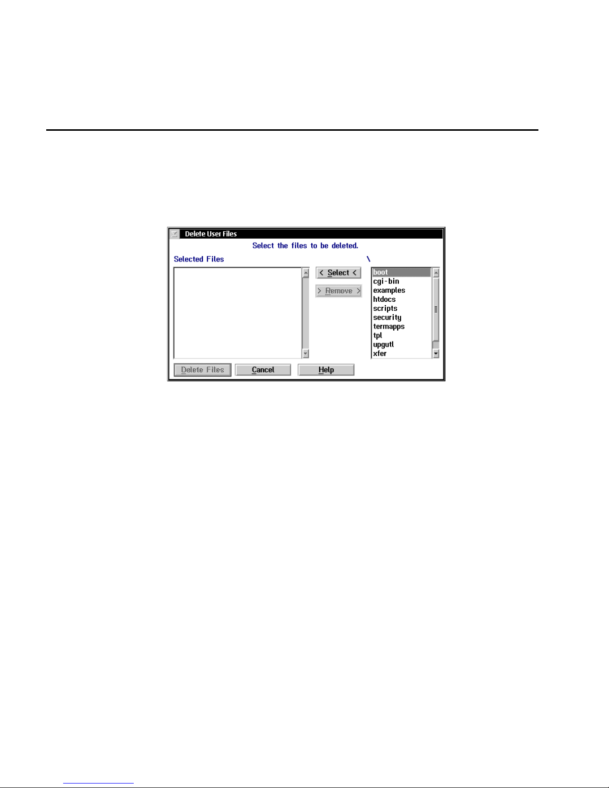
2. In the File Handling list box, select Delete User Files and then choose Start. The
Delete User Files dialog box appears.
3. In the root directory list box (\), add all the files that you want to delete to the
Selected Files list box.
a. Select the file name.
b. Choose Select. The file name appears in the Selected Files list box.
4. In the Selected Files list box, remove any of the files that you do not want to delete.
a. Select the file name.
b. Choose Remove. The file name is removed from the Selected Files list box.
5. Choose Delete Files. A message box appears confirming that you want to delete the
files.
6. Choose Delete. The DCS 300 deletes the user files you selected.
2-22
Page 65
Learning About the DCS 300
Starting and Stopping the Downline Network
You can manage data collection either from the DCS 300 local interface or using the
Web browser interface.
Starting Data Collection
Before the DCS 300 can communicate with the data collection network, you must start
data collection. You can configure the DCS 300 to automatically start the downline
network each time it reboots. For help, see “Setting the System Parameters” earlier in
this chapter and the online help.
To start data collection using the DCS 300 local interface
1. From the main screen sidebar buttons, choose Save and Activate. A message box
appears confirming that you want to save your changes and activate the
configuration.
2. Choose Activate. A message box may appear informing you that the DCS 300
needs to reboot and that you need to choose OK. Or, a message box may appear
informing you that your activate is successful.
2
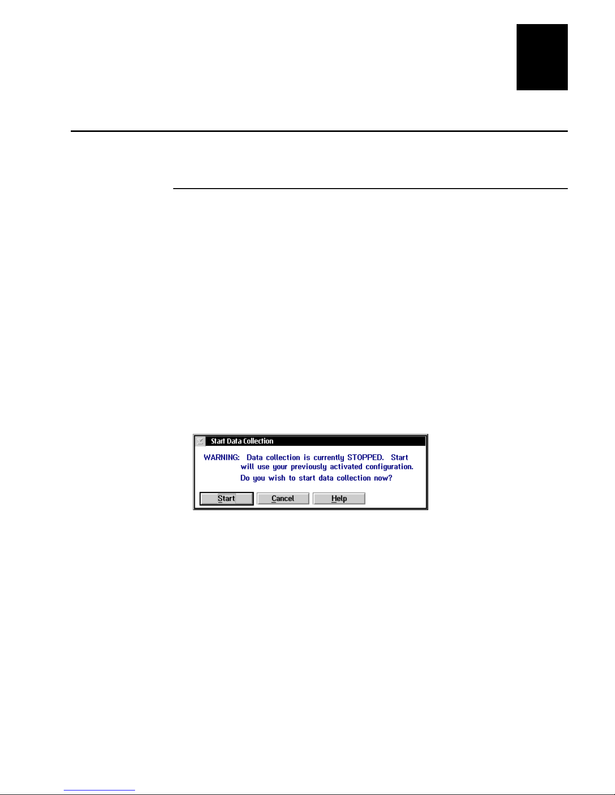
3. From the main screen sidebar buttons, choose Start Data Collection. The Start Data
Collection message box appears.
4. Choose Start. The title bar shows “Data Collection: RUNNING.”
To start data collection using the Web browser interface
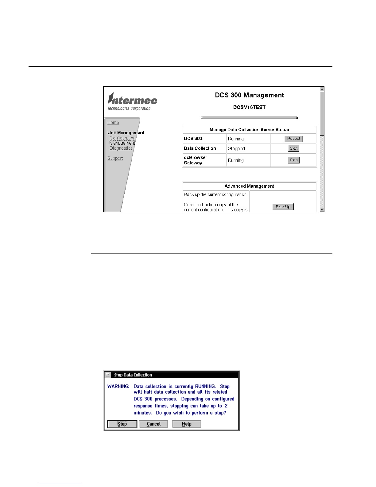
1. From the DCS 300 home page, click Management.
2. If a security screen appears, type
Password field, and click OK. You must type Intermec in uppercase letters.
3. In the Data Collection row, click Start. A message box appears confirming that you
want to start data collection.
INTERMEC
in the User Name field and in the
2-23
Page 66
DCS 300 User’s Manual
DCS 300 Management Page
4. Click OK. The Data Collection Starting page appears and a message box appears
informing you that data collection has been started.
Stopping Data Collection
You may need to stop data collection on the DCS 300 to update its configuration file.
When you stop data collection, all data collection activities are stopped, but any
external Intermec controllers continue polling and buffering data. Devices using
programs that require a response directly from a destination (interactive mode) also
stop until the DCS 300 is started again.
The Web browser interface uses the term downline network instead of data collection.
To stop data collection using the DCS 300 local interface
1. From the main screen sidebar buttons, choose Stop Data Collection. The Stop Data
Collection message box appears.
2-24
Page 67
Learning About the DCS 300
2. Choose Stop. The title bar shows “Data Collection: STOPPED.”
To stop data collection using the Web browser interface
1. From the DCS 300 home page, click Management.
2
2. If a security screen appears, type
Password field, and click OK. You must type Intermec in uppercase letters.
3. In the Data Collection row, click Stop. A message box appears confirming that you
want to stop data collection.
4. Click OK. The Data Collection Stopping page appears and then a message box
appears informing you that data collection has been stopped.
Accessing a Command Prompt
While maintaining or configuring the DCS 300, you may find your task is easier by
accessing a command prompt. You can get to a command prompt from either the
DCS 300 local interface or using telnet.
To access a command prompt using the local interface
1. From the main screen sidebar buttons, choose System Maintenance. The System
Maintenance dialog box appears.
2. In the System Maintenance list box, select DCS 300 Command Prompt and then
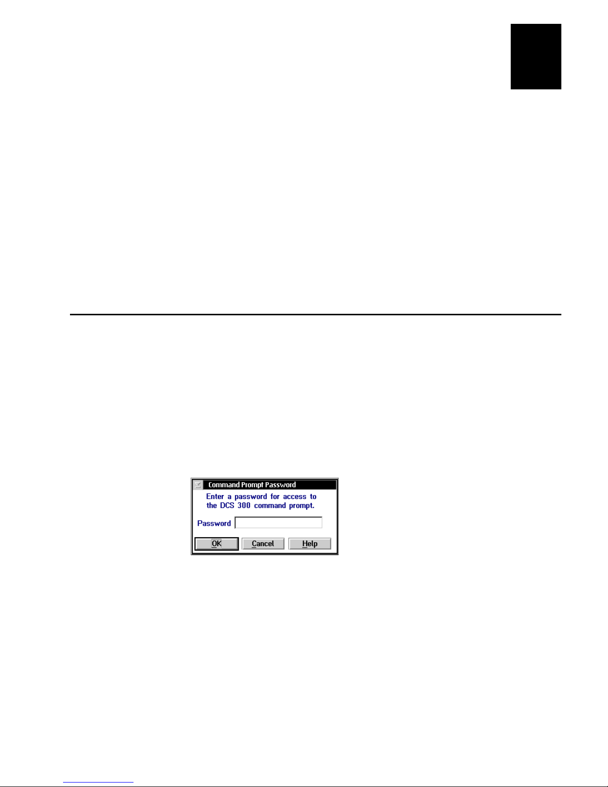
choose Start. The Command Prompt Password dialog box appears.
INTERMEC
in the User Name field and in the
3. In the Password field, type:
INTERMEC
4. Choose OK. The DCS 300 Command Prompt window appears.
2-25
Page 68

blank
Page 69

3
Connecting to the Upline Network
Page 70

DCS 300 System Manual
blank
3-2
Page 71

This chapter describes how to install the DCS 300 in your upline network and how to
configure the network adapter card.
Chapter Checklist
Done? Task Page
Y
Y
Y
Y
Y
Y
Connecting to the Upline Network
Install and configure the DCS 300 in the Ethernet network. 3-4
Install and configure the DCS 300 in the token ring network. 3-11
Install and configure the DCS 300 in the twinaxial network. 3-17
Install and configure the DCS 300 in the SDLC network. 3-18
Understand how to use and configure the IP routes. 3-21
Understand how to use and configure the auto fallback feature. 3-23
3
Save your runtime configuration. 3-25
Y
DCS 300 v1.3 and later does not support a connection to the coaxial network.
Note:
If you already understand and have performed these tasks, either connect the DCS 300
to another host or set up the host environment as described in these chapters:
Chapter 4, “Connecting to the Intermec RF Network”
•
Chapter 5, “Connecting to the 9180 and the Intermec CrossBar Network”
•
3-3
Page 72
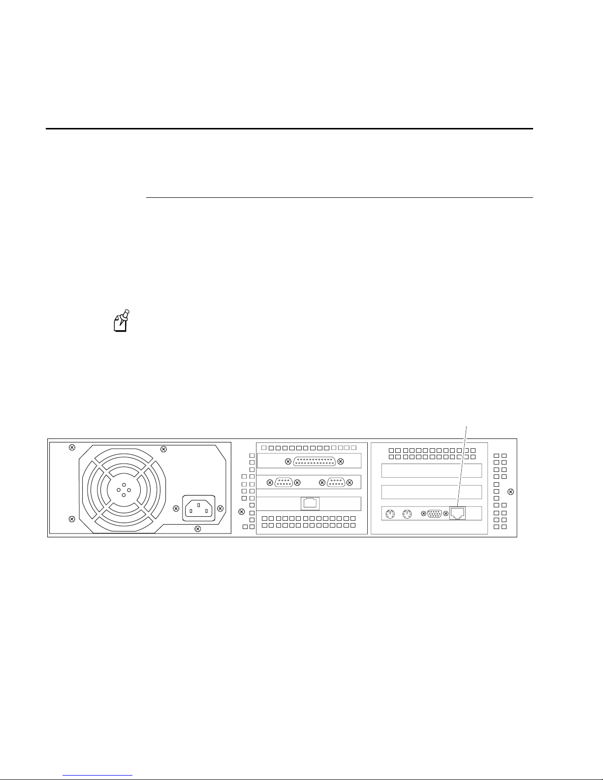
DCS 300 User’s Manual
300U022 .eps
Ethernet
port
Connecting to an Ethernet Network
To connect the DCS 300 to an Ethernet network, you must attach it to the wired
network and then you must configure the card. The Ethernet card supports both TCP/IP
and IEEE 802.2 protocols.
Installing the DCS 300
The DCS 300 has a built-in Ethernet interface.
Equipment needed
An Ethernet cable that meets the requirements of your Ethernet network, such as an
•
Ethernet CAT5 cable.
The default configuration for the Ethernet interface is 10BaseT or 100BaseTX.
Note:
To install the DCS 300
1. Locate the Ethernet port.
2. Insert one end of the cable into the Ethernet port and the other end into the Ethernet
connection.
3-4
Page 73

Connecting to the Upline Network
3
Configuring the Ethernet Card for TCP/IP
After you install the DCS 300, you need to turn it on and configure the Ethernet
network adapter card. To configure the card for TCP/IP, you can either use a Dynamic
Host Configuration Protocol (DHCP) server to provide the TCP/IP information or you
can enter the configuration manually. If you do not enter an IP address and you do not
check the Use DHCP check box, TCP/IP communications are disabled.
Use a DHCP server to provide TCP/IP information You can configure the DCS 300 to
be a DHCP client in a network that uses a DHCP server. The DHCP server can provide
the DCS 300 with an IP address and other basic IP configuration characteristics, such as
the subnet mask, the router IP address, and the DNS server address.
The DCS 300 supports only one network adapter card that is using DHCP.
Note:
However, the DCS 300 cannot be a DHCP client and a DHCP server. If you are using
the DCS 300 as a DHCP server for your Intermec data collection network, you must
enter the TCP/IP information manually.
If you have a backup DCS 300 that is also configured as a DHCP client, you do not
need to enter its IP address in each of your UDP Plus devices or your WTP devices
when it comes online. If you leave the backup DCS 300 online, you can perform pseudo
load-balancing on your UDP Plus network. For help, see “Using the Auto Fallback
Feature” later in this chapter.
Enter the TCP/IP information manually From your network administrator, obtain a
valid IP v4 address for each Ethernet card. You may also need to know the DCS 300
local host name and the subnet mask. Enter this information in the TCP/IP Protocol
Configuration dialog box. If you have two or more cards communicating using TCP/IP,
each card must be on a different subnet.
DNS Configuration In the TCP/IP Protocol Configuration dialog box, click the DNS
button to configure Domain Name System servers. You can use DNS servers to
translate the names or hosts and devices into IP addresses. For help, see “Using DNS”
later in this section.
Routing In the TCP/IP Protocol Configuration dialog box, click the Routing button to
configure a routing daemon or routing tables. You can choose to use a routing daemon
to maintain your routing tables or you can configure explicit routes. If you want to set
up explicit routes, you must know the type of route, the IP addresses of the route
destinations, and the IP addresses of the routers. Obtain this information from your
network administrator. For help, see “Configuring IP Routes” later in this chapter.
To configure the Ethernet card
1. From the main screen, choose the type of host environment you are using to
communicate between the DCS 300 and the host.
2. Choose Local Network Adapter. Four buttons for different network adapter card
types appear.
3-5
Page 74
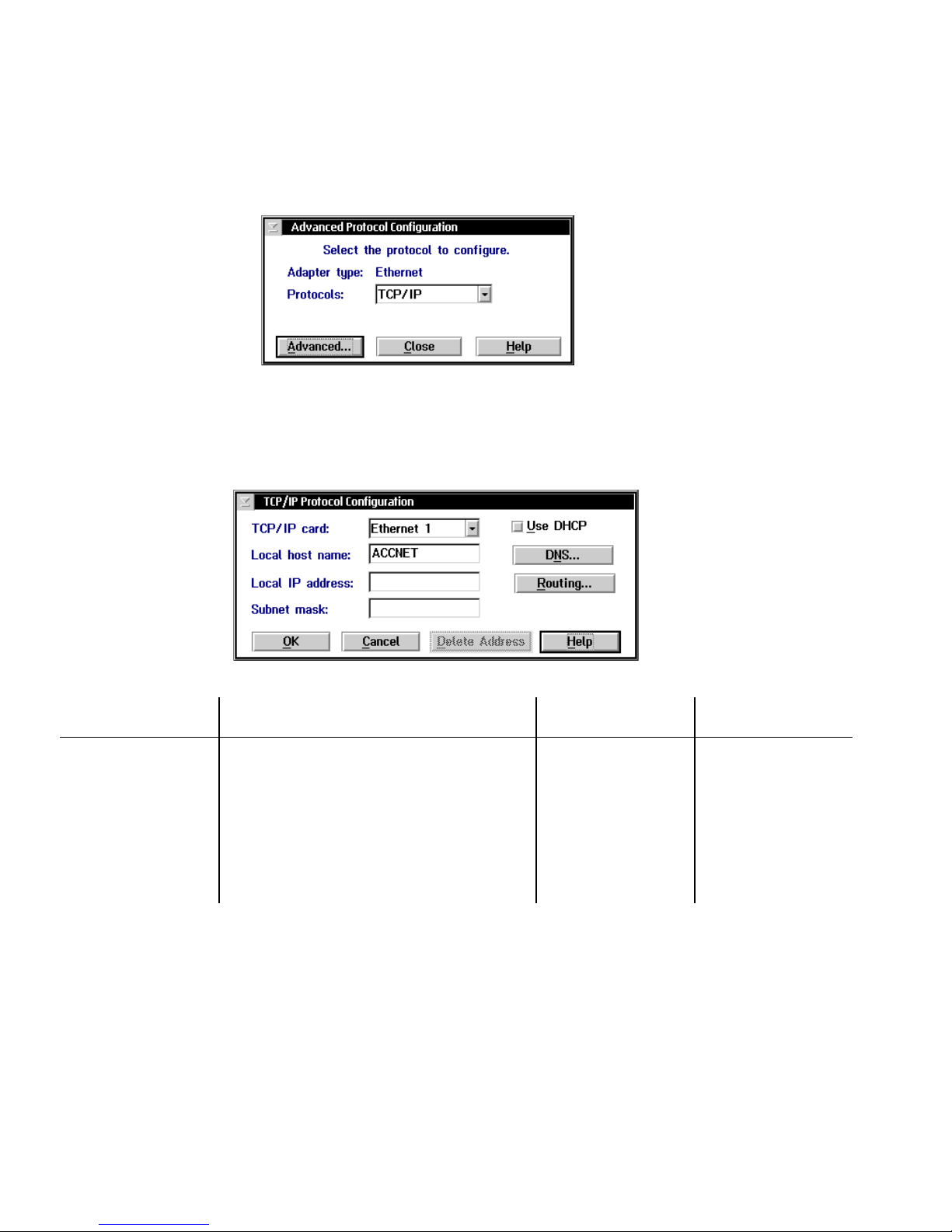
DCS 300 User’s Manual
3. Choose Ethernet. The Advanced Protocol Configuration dialog box appears.
4. In the Protocols field, click the down arrow on the right side of the field. Select
TCP/IP.
5. Choose Advanced. The TCP/IP Protocol Configuration dialog box appears.
Field Description Value Default
TCP/IP card The Ethernet adapter that you are configuring. Ethernet 1
Token Ring 1
Use DHCP This check box enables this network adapter
card to be administered by a DHCP server.
Local host name
(Optional)
A meaningful name that identifies the
DCS 300 (host) to the network.
Check, Clear Clear
1 to 12
alphanumeric
characters
Ethernet 1
ACCNET
3-6
Page 75

Connecting to the Upline Network
Field Description Value Default
3
Local IP address A unique IP address that identifies the card in
the DCS 300 (host) to the network. This IP
address must be a valid IP v4 address.
Subnet mask The mask that is used in the IP layer to
separate the subnet address from the local IP
address.
Using DNS
The DCS 300 supports the use of Domain Name System (DNS) servers in your
network. DNS lets you configure single or multiple name servers, which will resolve
name/IP address conversions of hosts and devices. The DCS 300 automatically obtains
the IP addresses from the DNS server, along with any changes. For example, if you use
a DNS server, you do not need to configure the DCS 300 with the IP addresses for the
TCP/IP hosts. You only need to enter the host names. However, if you manually enter
an IP address, this address takes precedence over an address supplied by the DNS
server.
In a DHCP environment, the IP address changes frequently. The host may obtain a new
IP address every time it is restarted and reconnects to the network. DNS servers let the
DCS 300 locate and connect to TCP/IP hosts that are administered by a DHCP server.
The DCS 300 locates the host by using the name to look up the host’s current IP
address, as registered in the DNS server.
y.x.x.x
where y is a
value between 1 and
223 (not including
127) and x is a value
between 0 and 255
x.x.x.x
where x is a
value between 0 and
255
None
Calculated based on
IP address
If you have a DNS server, you can use the local host name to open the DCS 300 home
page instead of the IP address. The local host name configured in the DCS 300 must
match the host name for the DCS 300 on the DNS server. For help configuring the DNS
server, see the documentation that came with your server.
Note:
In the local interface, any changes to the DNS Configuration dialog box become
active when you choose OK.
3-7
Page 76
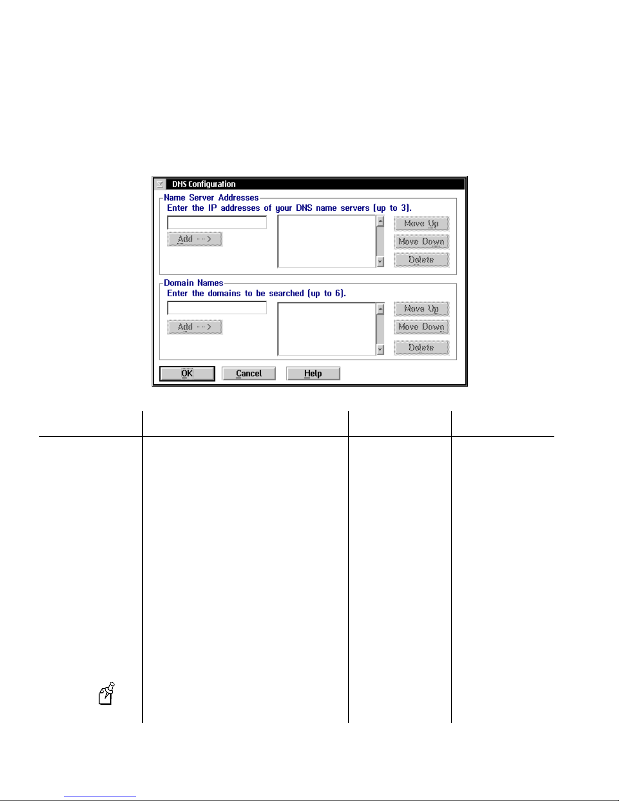
DCS 300 User’s Manual
To configure the DCS 300 to use DNS
From the TCP/IP Protocol Configuration dialog box, choose DNS. The DNS
•
Configuration dialog box appears.
Field Description Value Default
Name Server
Addresses
Domain Names List of domains that are searched when an
List of IP addresses of DNS servers that are
used to resolve IP addresses. You can enter up
to three IP addresses.
The first IP address in the list is the first DNS
server you want to use to resolve the IP
address. If the first DNS server does not
respond, then the DCS 300 uses the next IP
address. However, if the DNS server
responds, even if the response is a “not
resolved” response, the search stops.
abbreviated IP name is entered. You can enter
up to six domain names.
If the host or device name is not found in the
domain, the DCS 300 searches the next one.
The DCS 300 appends the complete domain
name before attempting to use the DNS server
to resolve the IP address.
If the host or device name has any
Note:
dotted notation, such as intermec.com, this list
is not used.
x.x.x.x where x is a
value between 0 and
255
256 alphanumeric
characters, dash
None
None
3-8
Page 77
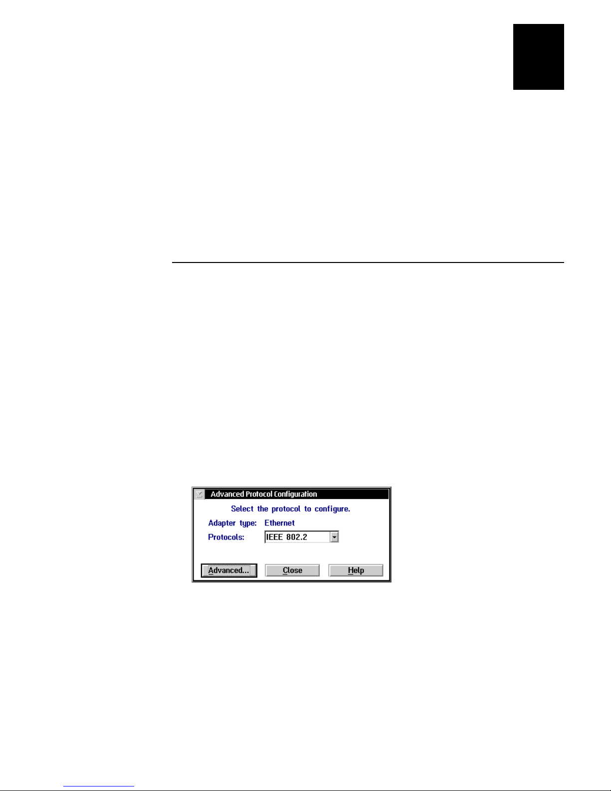
Connecting to the Upline Network
3
Clearing the IP Address and Subnet Mask
When you configure a card for TCP/IP and you do not use DHCP, you must enter the IP
address and subnet mask. From the TCP/IP Configuration dialog box of the local
interface, the Delete Address button lets you clear the Local IP address and Subnet
mask fields.
When you choose the Delete Address button, a message box appears warning you that
if you delete the IP address, routes and hosts that rely on this address may become
invalid. If you have a UDP Plus network defined and you have only one card defined
for TCP/IP, you must delete the UDP Plus network before you can clear the IP address
and subnet mask.
Configuring the Ethernet Card for IEEE 802.2
After you install the DCS 300, you need to turn it on and configure its network adapter
cards. Ethernet supports both TCP/IP and IEEE 802.2 protocols.
To configure the card for IEEE 802.2, you need to know the network adapter address,
Ethernet driver support, and the maximum number of link stations. This protocol is
used for IBM connectivity. It coexists with TCP/IP in the network adapter card.
To configure the Ethernet card
1. From the main screen, choose the type of host environment you are using to
communicate between the DCS 300 and the host.
2. Choose Local Network Adapter. Four buttons for different network adapter card
types appear.
3. Choose Ethernet. The Advanced Protocol Configuration dialog box appears.
4. In the Protocols field, click the down arrow on the right side of the field. Select
IEEE 802.2.
5. Choose Advanced. The IEEE 802.2 Adapter Protocol Configuration dialog box
appears.
3-9
Page 78
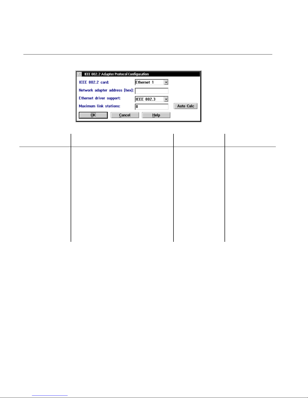
DCS 300 User’s Manual
IEEE 802.2 Adapter Protocol Configuration Dialog Box
Field Description Value Default
IEEE 802.2 card The Ethernet adapter that you are configuring. Ethernet 1
Token Ring 1
Network adapter
address (Optional)
Ethernet driver
support
Maximum link
stations
The locally administered MAC address in
IEEE format (hex) that identifies the card.
The Ethernet frame type you are using. IEEE 802.3 or
The maximum number of link stations that can
exist for all SAPs concurrently.
Or, choose the Auto Calc button if you want
the DCS 300 to determine the optimal values
for this field based on how it is configured.
020000000000
through
FEFFFFFFFFFF
Ethernet DIX
(Ethernet II)
Based on how the
DCS 300 is
configured.
Ethernet 1
The MAC address
that is on the card.
IEEE 802.3
8
3-10
Page 79

Connecting to the Upline Network
0300U022.eps
Connecting to a Token Ring Network
To connect the DCS 300 to a token ring network, you must attach it to the wired
network and then you must configure the card. The token ring card supports both
TCP/IP and IEEE 802.2 protocols.
The token ring card is not available on the 0300D.
Note:
Installing the DCS 300
You may have a token ring card in your DCS 300 that runs at 4, 16, or 100 Mbps. If you
use a token ring switch, this card can provide full-duplex communications. The
DCS 300 can only contain one token ring card and it must be in the first PCI slot, which
is the PCI slot that is farthest right when you are looking at the rear panel of the
DCS 300.
Equipment needed
3
A token ring connection where you can connect the DCS 300.
•
A cable to connect the DCS 300 to the connection. Your token ring card comes
•
with an RJ-45 to STP cable.
To install the DCS 300
1. Locate the slot that contains the token ring card. The card connectors look like the
figure below.
2. Insert one end of the cable into the token ring port on the card and the other end
into the token ring connection.
Configuring the Token Ring Card for TCP/IP
After you install the DCS 300, you need to turn it on and configure the token ring
network adapter card. To configure the card for TCP/IP, you can either use a Dynamic
Host Configuration Protocol (DHCP) server to provide the TCP/IP information or you
can enter the configuration manually. If you do not enter an IP address and you do not
check the Use DHCP check box, TCP/IP communications are disabled.
3-11
Page 80

DCS 300 User’s Manual
Use a DHCP server to provide TCP/IP information You can configure the DCS 300 to
be a DHCP client in a network that uses a DHCP server. The DHCP server can provide
the DCS 300 with an IP address and other basic IP configuration characteristics, such as
the subnet mask, the router IP address, and the DNS server address.
The DCS 300 supports only one network adapter card that is using DHCP.
Note:
However, the DCS 300 cannot be a DHCP client and a DHCP server. If you are using
the DCS 300 as a DHCP server for your Intermec data collection network, you must
enter the TCP/IP information manually.
If you have a backup DCS 300 that is also configured as a DHCP client, you do not
need to enter its IP address in each of your UDP Plus devices when it comes online. If
you leave the backup DCS 300 online, you can perform pseudo load-balancing on your
UDP Plus network. For help, see “Using the Auto Fallback Feature” later in this
chapter.
Enter the TCP/IP information manually From your network administrator, obtain a
valid IP v4 address for the token ring card. You may also need to know the DCS 300’s
local host name and the subnet mask. Enter this information in the TCP/IP Protocol
Configuration dialog box. If you have two or more cards communicating using TCP/IP,
each card must be on a different subnet.
DNS button Click this button to configure Domain Name System servers. You can use
Domain Name System servers to translate names of hosts and devices into IP addresses.
For help, see “Using DNS” later in this section.
Routing button Click this button to configure a routing daemon or routing tables. You
can choose to use a routing daemon to maintain your routing tables or you can
configure explicit routes. If you want to set up explicit routes, you must know the type
of route, the IP addresses of the route destinations, and the IP addresses of the routers.
Obtain this information from your network administrator. For help, see “Configuring IP
Routes” later in this chapter.
To configure the token ring card
1. From the main screen, choose the type of host environment you are using to
communicate between the DCS 300 and the host.
2. Choose Local Network Adapter. Four buttons for different network adapter card
types appear.
3. Choose Token Ring. The Advanced Protocol Configuration dialog box appears.
3-12
Page 81
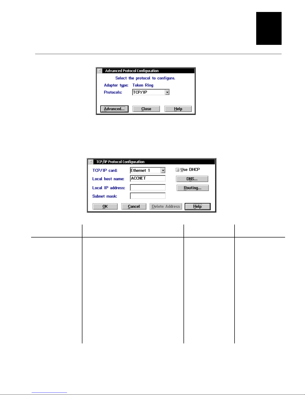
Advanced Protocol Configuration Dialog Box
4. In the Protocols field, click the down arrow on the right side of the field. Select
TCP/IP.
5. Choose Advanced. The TCP/IP Configuration dialog box appears.
Connecting to the Upline Network
3
Field Description Value Default
TCP/IP card The token ring adapter that you are
configuring.
Use DHCP This check box enables this network adapter
card to be administered by a DHCP server.
Local host name
(Optional)
Local IP address A unique IP address that identifies the card in
Subnet mask The mask that is used in the IP layer to
A meaningful name that identifies the
DCS 300 (host) to the network.
the DCS 300 (host) to the network. This IP
address must be a valid IP v4 address.
separate the subnet address from the local IP
address.
Token Ring 1 Ethernet 1
Check, Clear Clear
1 to 12
alphanumeric
characters
y.x.x.x
where y is a
value between 1 and
223 (not including
127) and x is a value
between 0 and 255
x.x.x.x
where x is a
value between 0 and
255
ACCNET
None
Calculated based on
IP address
3-13
Page 82
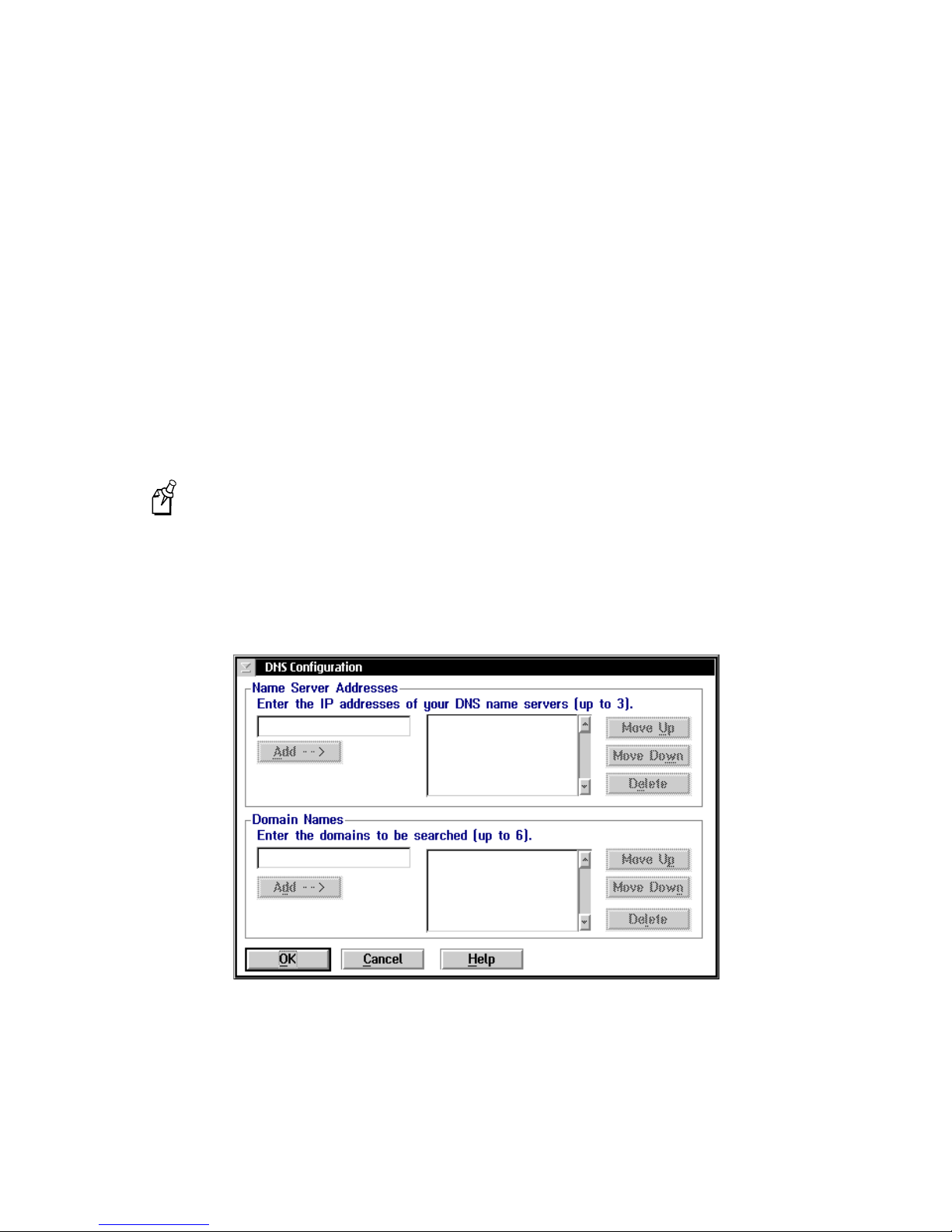
DCS 300 User’s Manual
Using DNS
The DCS 300 supports the use of Domain Name System (DNS) servers in your
network. DNS lets you configure single or multiple name servers, which will resolve
name/IP address conversions of hosts and devices. The DCS 300 automatically obtains
the IP addresses from the DNS server, along with any changes. For example, if you use
a DNS server, you do not need to configure the DCS 300 with the IP addresses for the
TCP/IP hosts. You only need to enter the host names. However, if you manually enter
an IP address, this address takes precedence over an address supplied by the DNS
server.
In a DHCP environment, the IP address changes frequently. The host may obtain a new
IP address every time it is restarted and reconnects to the network. DNS servers let the
DCS 300 locate and connect to TCP/IP hosts that are administered by a DHCP server.
The DCS 300 locates the host by using the name to look up the host’s current IP
address, as registered in the DNS server.
Any changes to the DNS Configuration dialog box become active when you
Note:
choose OK.
To use DNS
From the TCP/IP Protocol Configuration dialog box, choose DNS. The DNS
•
Configuration dialog box appears.
3-14
Page 83

Connecting to the Upline Network
Field Description Value Default
3
Name Server
Addresses
Domain Names List of domains that are searched when an
List of IP addresses of DNS servers that are
used to resolve IP addresses. You can enter up
to three IP addresses.
The first IP address in the list is the first DNS
server you want to use to resolve the IP
address. If the first DNS server does not
respond, then the DCS 300 uses the next IP
address. However, if the DNS server
responds, even if the response is a “not
resolved” response, the search stops.
abbreviated IP name is entered. You can enter
up to six domain names.
If the host or device name is not found in the
domain, the DCS 300 searches the next one.
The DCS 300 appends the complete domain
name before attempting to use the DNS server
to resolve the IP address.
Note: If the host or device name has any
dotted notation, such as intermec.com, this list
is not used.
x.x.x.x where x is a
value between 0 and
255
256 alphanumeric
characters, dash
None
None
Configuring the Token Ring Card for IEEE 802.2
After you install the DCS 300, you need to turn it on and configure its network adapter
cards. Token ring supports both TCP/IP and IEEE 802.2 protocols.
To configure the card for IEEE 802.2, you need to know the network adapter address,
Ethernet driver support, and the maximum number of link stations. This protocol is
used for IBM connectivity. It coexists with TCP/IP in the network adapter card.
To configure the token ring card
1. From the main screen, choose the type of host environment you are using to
communicate between the DCS 300 and the host.
2. Choose Local Network Adapter. Four buttons for different network adapter card
types appear.
3. Choose Token Ring. The Advanced Protocol Configuration dialog box appears.
3-15
Page 84
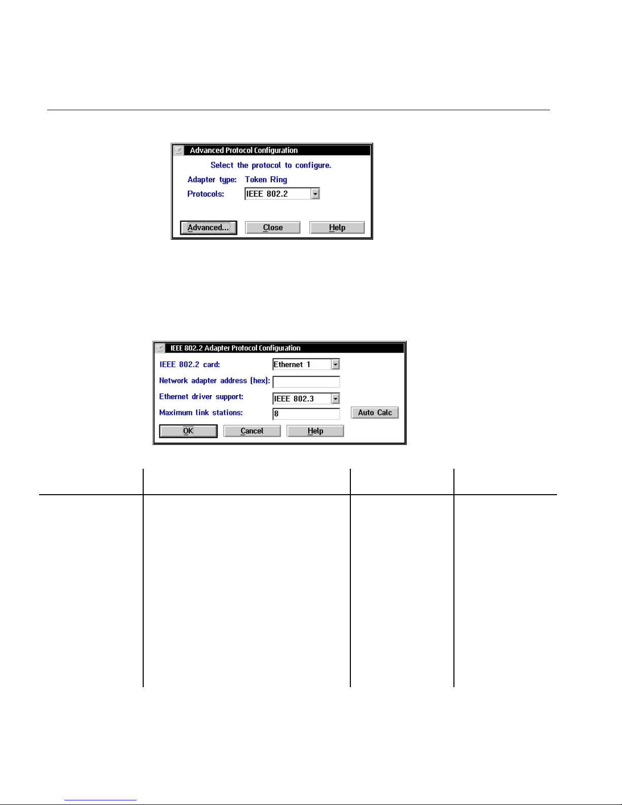
DCS 300 User’s Manual
Advanced Protocol Configuration Dialog Box
4. In the Protocols field, click the down arrow on the right side of the field. Select
IEEE 802.2.
5. Choose Advanced. The IEEE 802.2 Adapter Protocol Configuration dialog box
appears.
Field Description Value Default
IEEE 802.2 card The token ring adapter that you are
configuring.
Network adapter
address (Optional)
Ethernet driver
support
Maximum link
stations
The locally administered MAC address in
IEEE format (hex) that identifies the card.
The Ethernet frame type you are using. IEEE 802.3 or
The maximum number of link stations that can
exist for all SAPs concurrently.
Or, choose the Auto Calc button if you want
the DCS 300 to determine the optimal values
for this field based on how it is configured.
Token Ring 1 Ethernet 1
020000000000
through
FEFFFFFFFFFF
Ethernet DIX
(Ethernet II)
Based on how the
DCS 300 is
configured.
The MAC address
that is on the card
IEEE 802.3
8
3-16
Page 85

Connecting to the Upline Network
300U021.eps
Connecting to a Twinaxial Network
To connect the DCS 300 to a twinaxial network, you must attach it to the wired
network and then you must configure the card. The DCS 300 can only contain one
twinaxial card and it must be in the first ISA slot, which is the ISA slot that is farthest
right when you are looking at the rear panel of the DCS 300.
The twinaxial card is not available on the 0300D.
Note:
Installing the DCS 300
Equipment needed
A twinaxial connection where you can connect the DCS 300.
•
A cable to connect the DCS 300 to the connection. You can use a 15 conductor
•
IBM custom cable for a twinaxial connection.
3
To install the DCS 300
1. Locate the slot that contains the twinaxial card on the rear panel of your DCS 300.
The twinaxial card is the card that is farthest right when you are facing the rear
panel. Refer to the figure below.
2. Insert one end of the cable into the port and the other end into the twinaxial
connection.
Configuring the Twinaxial Card
After you install the DCS 300, you need to turn it on and configure its network adapter
cards.
Before you configure the network adapter card, obtain the DCS 300 address and the
maximum I-field size from your network administrator.
To configure the twinaxial card
1. From the main screen, choose the type of host environment you are using to
communicate between the DCS 300 and the host.
3-17
Page 86
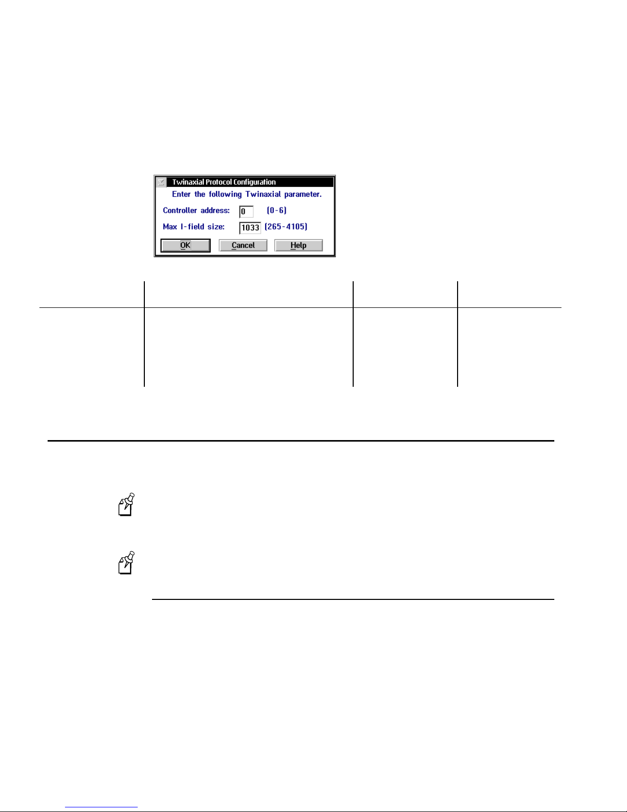
DCS 300 User’s Manual
2. Choose Local Network Adapter. Four buttons for different network adapter card
types appear.
3. Choose Twinaxial. The Twinaxial Protocol Configuration dialog box appears.
Field Description Value Default
Controller address The address of the host twinaxial connection.
This value must be unique for each twinaxial
device connected to the host on this line.
Max I-field size The maximum frame size that is used in this
connection mode.
Connecting to an SDLC Network
To connect the DCS 300 to an SDLC network, you must attach it to the wired network
and then you must configure the card.
The SDLC card uses COM1. If you need more than one available serial port
Note:
(COM2), you can contact your local Intermec representative and purchase an Intermec
serial I/O board.
The SDLC card is not available on the 0300D.
Note:
Installing the DCS 300
0 to 6 0
265 to 4105 1033
Equipment needed
An SDLC connection where you connect the DCS 300.
•
An SDLC cable to connect the DCS 300 to the connection. You can use a 25
•
conductor IBM custom cable.
3-18
Page 87
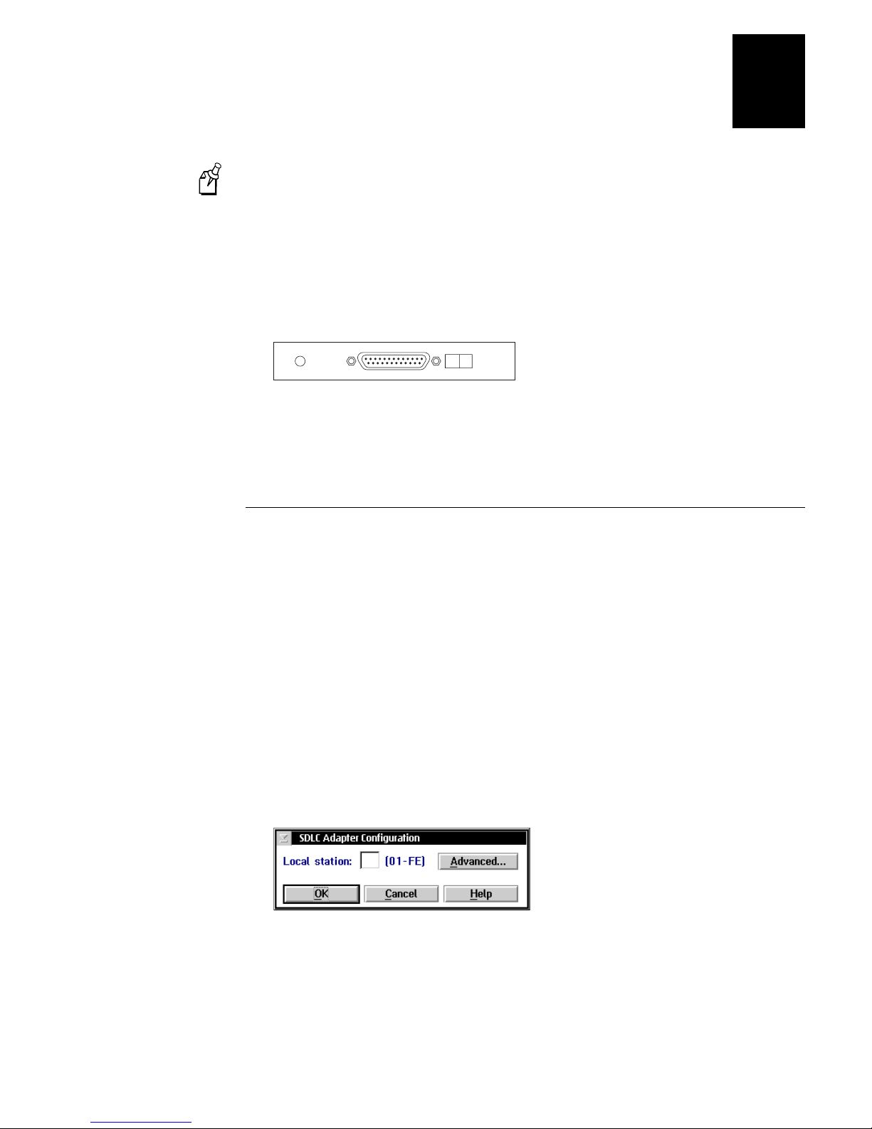
Connecting to the Upline Network
0300U024.eps
The default configuration for the SDLC card is V.35. Contact your local
Note:
Intermec representative if you need to use RS-232 communications.
To install the DCS 300
1. Locate the slot that contains the SDLC card on the rear panel of your DCS 300. The
SDLC card is the card that is farthest right when you are facing the front panel. The
connector on the card looks like the figure below.
2. Insert one end of the cable in the port on the card and the other end in the
connection.
3
Configuring the SDLC Card
After you install the DCS 300, you need to turn it on and configure its network adapter
cards. The SDLC card can use an internal or external clock at speeds up to 1.5 Mbps.
Before you configure the network adapter card, obtain the local station address from
your network administrator. You may also need to know the line type, line mode, NRZI,
link station role, and maximum I-field size.
To configure the SDLC card
1. From the main screen, choose the type of host environment you are using to
communicate between the DCS 300 and the host.
2. Choose Local Network Adapter. Four buttons for different network adapter card
types appear.
3. Choose SDLC. The SDLC Adapter Configuration dialog box appears.
4. In the Local station field, enter the address (in hex) that identifies the DCS 300
station. The address can be from 01 to FE. The default is 01.
3-19
Page 88
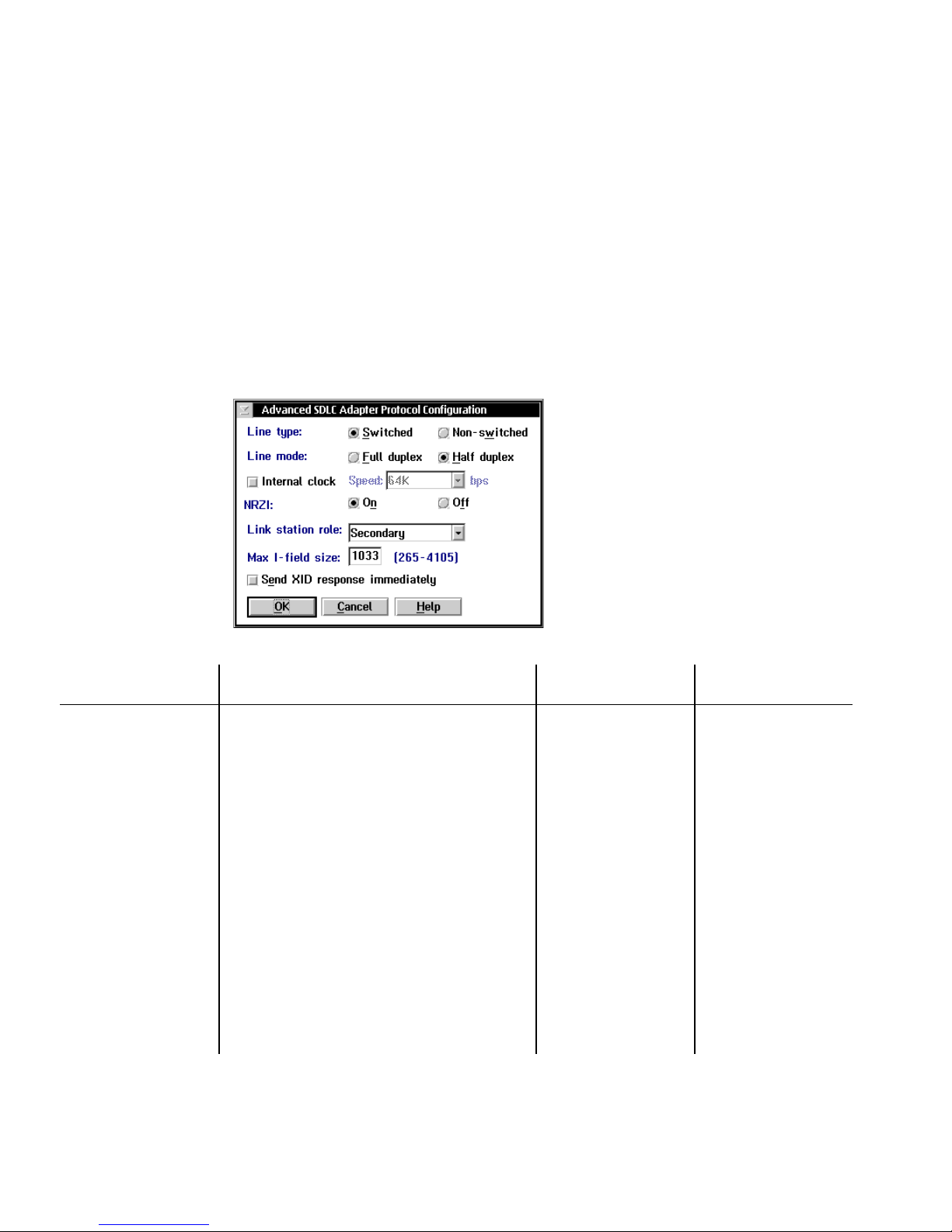
DCS 300 User’s Manual
5. Configure any advanced SDLC parameters. For help, see “Configuring Advanced
SDLC Parameters” in the next section.
6. Choose OK to return to the SDLC Adapter Configuration dialog box.
7. Choose OK to return to the main screen.
Configuring Advanced SDLC Parameters
From the SDLC Adapter Configuration dialog box, choose Advanced. The
•
Advanced SDLC Adapter Protocol Configuration dialog box appears.
Field Description Value Default
Line type The type of telecommunications link that the
DCS 300 is using. Switched lines are the
dialed type. Non-switched lines are the leased
type.
Line mode The type of cable you are using to connect the
DCS 300 to your host.
Internal clock This check box determines if you are using an
internal or external clock.
Speed The speed (in bps) of the internal clock. 4800, 9600, 19.2K,
NRZI
(Non-Return-to-Zero
Inverted)
The data encoding for modems that are
sensitive to certain bit patterns.
Switched,
Non-switched
Full duplex,
Half duplex
Check, Clear Clear
38.4K, 56K, 64K,
128K, 192K, 256K,
384K, 560K, 840K,
960K, 1008K
On, Off On
Switched
Half duplex
64K
3-20
Page 89

Connecting to the Upline Network
Field Description Value Default
3
Link station role This field sets the role of the DCS 300 to be
the primary workstation or the secondary
workstation to the host.
If you are configuring 3270 SNA terminal
emulation or you are communicating with a
mainframe, this field is typically Secondary.
Choose Negotiable if you want the DCS 300
and host to negotiate their roles when they
connect.
Max I-field size The maximum frame size that is used in this
connection mode.
Send XID response
immediately
This check box determines if the DCS 300
sends the XID response without waiting for
the host to send the XID request. This XID is
also the Node ID.
Configuring IP Routes
If your DCS 300 is running in a TCP/IP network, you can either use the routing daemon
to maintain a routing table or you can configure explicit IP routes.
Primary, Negotiable,
Secondary
265 to 4105 1033
Check, Clear Clear
Secondary
Using the Routing Daemon
The routing daemon initializes and dynamically maintains the routing table by
communicating with daemons on other systems to exchange routing information, such
as what networks are known by the machine on which the daemon is running. Routing
daemons exchange information according to routing protocols. Generally, the routing
daemon is sufficient for standard network configuration, but you may also configure
explicit IP routes. Obtain these routes from your network administrator.
If you cannot connect with a TCP/IP host in your network, you may have a routing
problem. Configuring an explicit route may resolve this problem.
To enable or disable the routing daemon
1. From the TCP/IP Protocol Configuration dialog box, choose Routing. The Routing
Table Entries Configuration dialog box appears.
3-21
Page 90
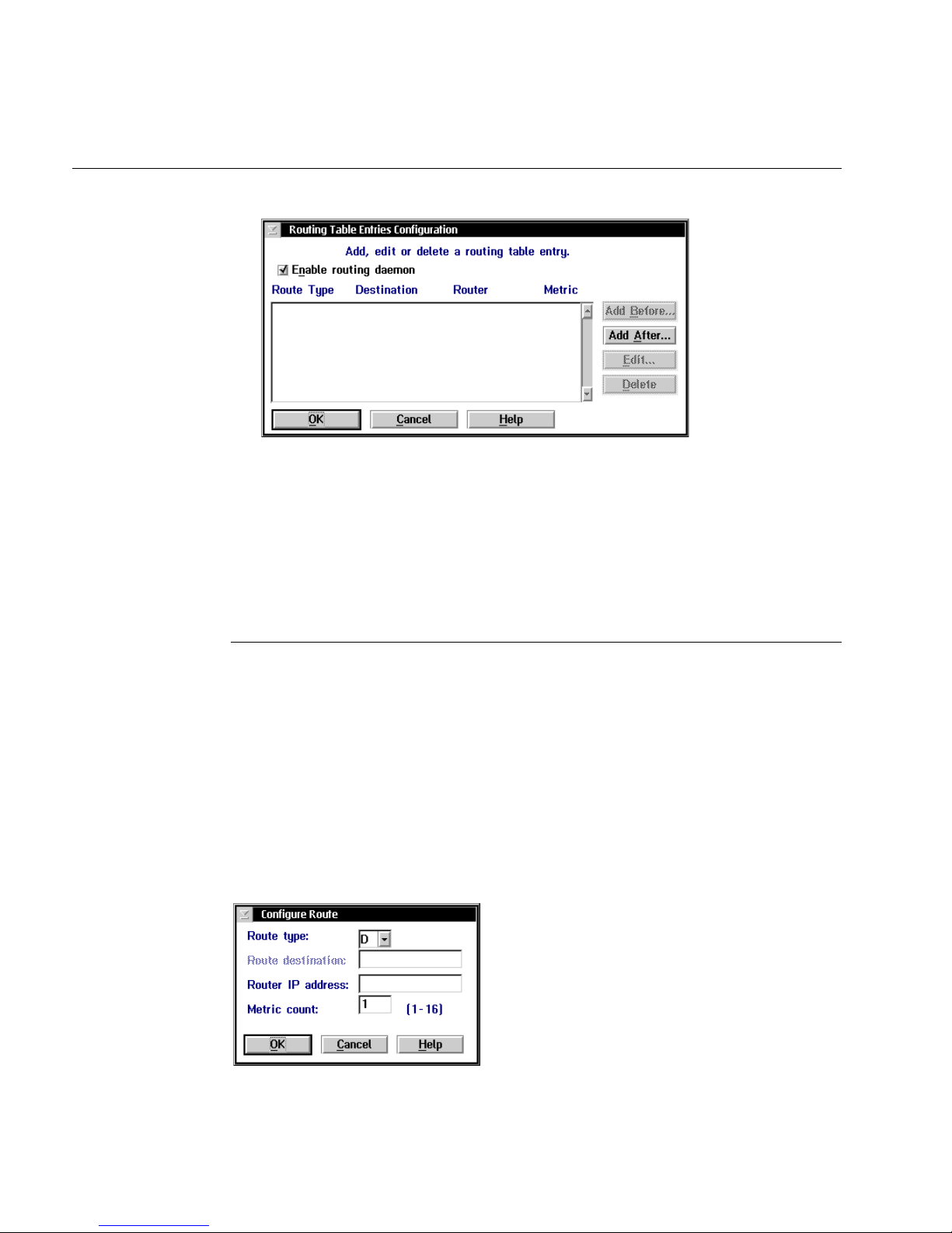
DCS 300 User’s Manual
Routing Table Entries Configuration Dialog Box
2. To enable the routing daemon, check the check box for Enable routing daemon.
Or, to disable the routing daemon, clear the check box for Enable routing daemon
and configure explicit routes. For help, see “Configuring Routing Tables” in the
next section.
3. Choose OK to save your changes and return to the TCP/IP Configuration dialog
box.
Configuring Routing Tables
There are four types of routes that you can configure: default, network, subnet, and
host. The default route specifies a route that can be used as a destination for an IP
packet if a route for the IP packet is not specified. Network routes define a network to
add to the system. Subnet routes define a subnet to add to the system. Host routes
define a specific host destination to add to the system.
To configure a route
From the Routing Table Entries Configuration dialog box, choose Add Before or
•
Add After. The Configure Route dialog box appears.
3-22
Page 91

Connecting to the Upline Network
Field Description Value Default
3
Route type The type of route you are configuring for a
destination.
Route destination
(N, S, H route types
only)
Router IP address The IP address of the router for the
Metric count The number of hops it takes to get to the
The IP address of the destination of the route
you are configuring.
destination you are configuring.
destination.
Using the Auto Fallback Feature
The Auto Fallback feature lets Trakker Antares UDP Plus terminals and WTP devices
switch from a DCS 300 that goes offline to a DCS 300 that is online with minimal
system disruption. This feature can also be useful if the DCS 300 is a client in a DHCP
environment where it gets a new IP address every time it is booted.
D=default
N=network
S=subnet
H=host
x.x.x.x
where x is a
value between 0 and
255
y.x.x.x
where y is a
value between 1 and
223 (not including
127) and x is a value
between 0 and 255
1 to 16 1
D
None
None
When Trakker Antares UDP Plus terminals are communicating with access points and
the DCS 300, the Connect icon is on. If the Connect icon blinks, the terminal is no
longer communicating with the DCS 300. If you have implemented the Auto Fallback
L
feature in your data collection network, simply press
obtain a new controller IP address. When the Connect icon is on, you can continue data
collection.
If your Connect icon blinks or turns off, you may be out of range of an access
Note:
point, you may be about to go out of range of an access point, or the access point may
have recently been turned off. Verify that you do not have an access point problem
before you try to obtain a new controller IP address.
When WTP devices are no longer communicating with the DCS 300, you can no longer
perform data collection. If you have implemented the Auto Fallback feature in your
data collection network, reboot the device. The terminal session will try to connect to
Host A, Host B, and then Host C. When it makes a connection, you can continue data
collection.
twice on your terminal to
3-23
Page 92

DCS 300 User’s Manual
Configuring the DCS 300s
You must configure each DCS 300 that you want to be available to use with the Auto
Fallback feature to accept connections from the terminals that you want to use with this
feature. To enable Trakker Antares UDP Plus terminals, see “Enabling the UDP Plus
Devices” in Chapter 4. You do not need to enable WTP devices.
Configuring the Trakker Antares UDP Plus Terminals
The Trakker Antares UDP Plus terminals must have firmware version 3.21 or later.
To configure the terminals to use the Auto Fallback feature
1. Configure the network parameters for the terminal, including the terminal IP
address and the controller IP Address. The controller IP address can be any valid IP
address. For help, see your terminal user’s manual.
2. Scan this bar code:
Enable DHCP
*/D/KNI1*
*$+NI1*
3. Press L twice.
The terminal looks for a DCS 300 on the network. When it locates a DCS 300, it resets
its controller IP address parameter to the IP address of the DCS 300 that it found.
Note:
If the terminals are in a different subnetwork than the DCS 300, you must
configure and enable the DHCP relay agent on the routers. For help, see your router
user’s manual.
Configuring the WTP Devices
The WTP devices must have firmware version 5.33 or later. You must configure the
network parameters for the device, including Host A, Host B, and Host C. For each of
these hosts, you define the communications mode, the terminal number, and the RF
host stack. The RF host is the DCS 300 to which you want the device to connect. When
a device is booted, the terminal session tries to connect with Host A, Host B, and then
Host C.
3-24
Page 93

Connecting to the Upline Network
Saving Your Runtime Configuration
When you finish configuring your network adapter card, you should save your changes.
To save your runtime configuration
From the main screen sidebar buttons, choose Save Configuration.
•
3
3-25
Page 94

blank
Page 95

4
Connecting to the Intermec RF Network
Page 96

DCS 300 System Manual
blank
Page 97

This chapter explains how to connect the DCS 300 to the 900 MHz RF network using
RF cards and 9181 Base Radio Units (BRUs). It also explains how to connect the
DCS 300 to the UDP Plus network using access points, JANUS devices, and Trakker
Antares terminals. It also explains how to connect the DCS 300 to the WTP network
using access points and WTP devices.
Chapter Checklist
Done? Task Page
Y
Y
Connecting to the Intermec RF Network
Connect the DCS 300 to your Ethernet or token ring network. 3-4
Connect the DCS 300 to your Intermec 900 MHz RF network. 4-4
4
Configure the RF cards in the DCS 300 to communicate with the
Y
BRUs.
Set the time parameters for the 900 MHz RF network. 4-10
Y
Configure your UDP Plus network. 4-18
Y
Set the time parameters for the UDP Plus network. 4-21
Y
Configure your WTP network. 4-31
Y
Edit the JANUS 900 MHz device parameters. 4-15
Y
Edit the UDP Plus device parameters. 4-27
Y
Edit the WTP device parameters. 4-38
Y
If you already understand and have performed these tasks, connect the DCS 300 to your
CrossBar network or host environment as described in these chapters:
Chapter 5, “Connecting to the 9180 and the Intermec CrossBar Network”
•
Chapter 6, “Running Data Collection Browser”
•
4-6
Chapter 7, “Running Terminal Emulation”
•
Chapter 8, “Running Peer-to-Peer Applications”
•
Chapter 9, “Running Terminal Sessions”
•
The 900 MHz card is not available on the 0300D. The 0300D can only connect to
Note:
a network through serial or Ethernet connections.
4-3
Page 98

DCS 300 User’s Manual
Connecting the DCS 300 to the 900 MHz RF Network
The DCS 300 can communicate with Intermec’s 900 MHz RF network. To
communicate with this network, the DCS 300 contains a 900 MHz RF card that
connects by an RS-485 cable to 9181 Base Radio Units (BRUs). This RF card supports
up to four ports. Devices can roam between these BRUs.
The 900 MHz card is not available on the 0300D. The 0300D can only connect to
Note:
a network through serial or Ethernet connections.
The BRUs transmit information from the DCS 300 to Intermec 900 MHz RF devices
and receive signals from them. The illustration on the next page shows an example of a
DCS 300 connected to the Intermec 900 MHz RF network.
To connect the DCS 300 and the BRU, Intermec provides you with a 4-port interface
cable. Insert one end of the cable into the port on the RF card. Use the Intermec cable
kit (Part No. 055003) or equivalent to connect to one of the DNLN ports on the other
end of the cable. You also need a Belden 89688 cable (Part No. 583326) or equivalent.
If you are using the 9180 Network Controller to communicate with the 9181
Note:
BRU, you need to configure these BRUs using the 9180 controller’s configuration
menu. Refer to your 9180 user’s manual.
4-4
Page 99
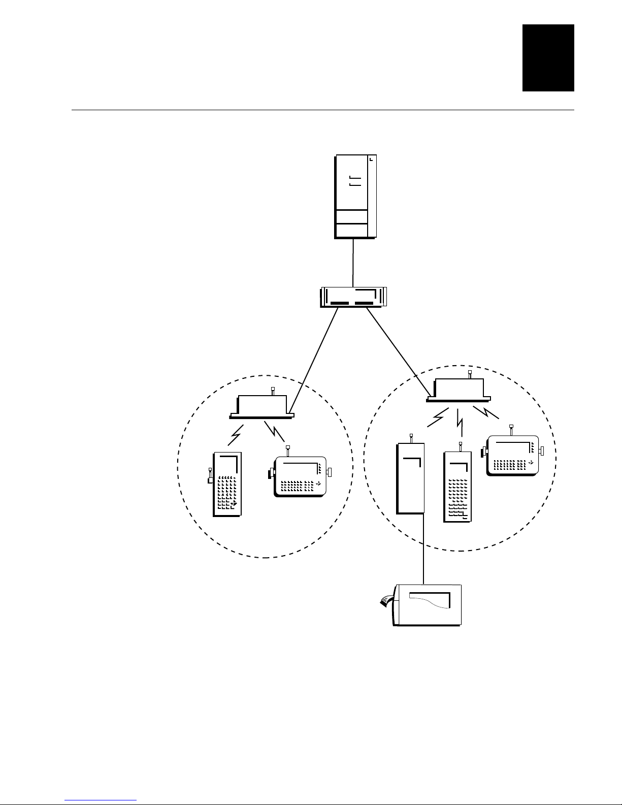
Connecting to the Intermec RF Network
Example: The DCS 300 Connected to the Intermec 900 MHz RF Network
Host
DCS 300
RS-485
4
9181
JR2020
RS- 485
9181
9450
J2050
9189
9465
RS-232
0300U016.eps
3400
4-5
Page 100
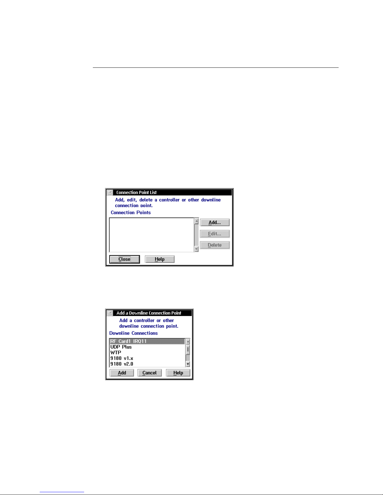
DCS 300 User’s Manual
Configuring the RF Card
You must configure the communications parameters, enable the BRUs, set the Hot
Standby timeout, and set any special time parameters for the RF card. The RF card must
have a unique RFNC address and a unique network ID.
To configure the RF card
1. From the main screen, choose the type of host environment you are using to
communicate between the DCS 300 and the host.
2. Choose Downline Network. Two buttons, Connection Points and Downline
Devices, appear.
3. Choose Connection Points. The Connection Point List dialog box appears.
4. Choose Add, Edit, or Delete. If you choose Add, the Add a Downline Connection
Point dialog box appears.
4-6
 Loading...